Article

A Model to Study the Creep Behavior of Carbon Fiber/Epoxy Resin Composites Under Temperature

1
School of Engineering and Design, Technical University of Munich, 80333 Munich, Germany
2
Department of Mechanical Engineering, Transilvania University of Brasov, 500036 Brasov, Romania
3
Institute of Solid Mechanics of Romanian Academy, Str. C. Mille, 15, 010141 Bucharest, Romania
*
Author to whom correspondence should be addressed.
Appl. Sci. 2025, 15(8), 4206; https://doi.org/10.3390/app15084206
Submission received: 12 March 2025 / Revised: 2 April 2025 / Accepted: 7 April 2025 / Published: 11 April 2025

Abstract

:
The mechanical characteristics of carbon fiber and epoxy resin composite materials are time-dependent and typically show viscoelastic behavior. Since the use of these materials in engineering applications has increased dramatically in recent decades, it is necessary to ascertain their mechanical properties with the utmost precision. Creep behavior is typically seen in composites made with epoxy resin, which has a viscoelastic behavior. In order to ascertain how these materials will behave over time when exposed to temperature changes, the authors of this research suggest a model using the least squares method. The experimental results verify the accuracy of that model. Engineers may find the results helpful in designing novel carbon fiber-based composite materials with an epoxy resin matrix.

1. Introduction

Carbon fiber-reinforced composites are commonly utilized materials in many engineering sectors because of their exceptional qualities. These characteristics dictate how these materials are used in a variety of fields, including medical equipment, electronics, automobile engineering, aerospace engineering, and the chemical industry. The materials are mostly utilized in applications that demand a high performance because of their greater manufacturing cost. This study focuses on composites composed of a carbon fiber-reinforced epoxy resin matrix.
The authors of this study provide an interpolator for the temperature behavior of a composite under axial force in order to quickly and effectively characterize the material’s creep behavior. The authors’ experimental data for varying temperatures and applied axial loads serve as the basis for the proposed interpolator. The material used for the experiment was Fibredux 6376 (known as HexPly® 6376) [1,2]. The properties of this material and the work conditions are described by standards ISO R527 [3] and 1 ISO 178 [4]. There is a rich literature that presents results concerning this material. We will present some basic research used in this study. Carbon fiber is a very widely known and used material in engineering applications, made primarily of carbon atoms bonded together in a crystalline structure. The main property is the strength-to-weight ratio, which makes carbon fibers incredibly strong, lightweight, and durable. These fibers are extremely stiff, which means they can withstand significant forces without breaking or bending. They are stronger than steel and much lighter (lighter than aluminum). At the same time, they have high thermal conductivity, so they can effectively dissipate heat. Carbon fibers do not rust or corrode.
The authors of this study provide an interpolator for the temperature behavior of a composite under axial force in order to quickly and effectively characterize the material’s creep behavior. The authors’ experimental data for varying temperatures and applied axial loads serve as the basis for the interpolator. Overall, the authors’ contributions consist of the following:
-
Development of an interpolator model for the study of the influence of temperature on the behavior of carbon fiber-reinforced composite materials;
-
Experimental measurements for the analysis of the method and the study of a material frequently used in engineering applications;
-
Creation of an experimental basis that can also serve as the basis for verifying other models.

2. Literature Review

These fibers are used in a variety of aerospace and automotive applications, sports equipment, wind turbine blades, medical devices, and the navy. Some main results concerning the use of composite materials made with carbon fibers in an epoxy matrix are presented in the following. Understanding the mechanisms of damage of carbon fiber epoxy resin composites (CFRPs) under laser irradiation has grown in importance as laser technology has continued to progress. One paper [5] investigates the impact on CFRP when changing laser irradiation characteristics, such as power densities and energy distributions inside the laser point. Computed tomography (CT), thermal analysis, and micro-morphological inspection were used to examine the CFRP damage mechanisms. A finite element model was created to model the carbon fiber epoxy resin composites’ laser irradiation process. Excellent agreement between the simulated and experimental results was shown. The paper offers a theoretical justification for improving CFRP safety in laser-intensive settings. Vacuum-assisted resin infusion (VARI)-fabricated carbon fiber composites have found widespread application across a range of sectors. The viscosity is greatly increased by inorganic nanoparticles that increase the strength and toughness of matrices, which complicates the VARI process [6]. These improvements are noticeably greater than those of CFRCs that have been individually modified by fiber sizing or matrix reinforcement. With improved physicochemical and mechanical properties, graphene-related materials (GRM) exhibit significant promise as reinforcement in polymeric matrices.
One interesting method to improve the fracture toughness of epoxy resin (ER) is to incorporate graphene nanoplatelets (GNPs) into the resin [7]. In order to identify the ideal circumstances for the incorporation of GNP-ER as a matrix to create hybrid laminated composites with carbon fiber fabric, this work sought to create nanocomposites based on ER and GNP by analyzing various mixing techniques and determining the impact of GNP content on the resins’ properties. According to tensile testing, ultrasonication increased the nanocomposites’ ultimate tensile strength (UTS) by about 14% and their deformation at break by up to 46%. A hygrothermal aging model describes how engineering constants in T700 carbon fiber/epoxy resin composites are damaged [8]. The model is validated by tensile tests, surface morphology evaluations, and mass change observations before and after seawater immersion. According to the findings, single-layer laminates may absorb saturated moisture at a rate of 0.35% when submerged in seawater. As moisture absorption increases, the longitudinal tensile modulus of the composite drops by an order of 10–5%, whereas there is a 10–3% drop in the other engineering constants. The longitudinal tensile modulus reduces by 0.84% while the other engineering constants decrease by 100% as the temperature rises.
The temperature dependency of fiber-reinforced composites can be approached in a variety of ways, and in many real-world applications, the impact of temperature is important. The Ramberg–Osgood connection is used in [9] to suggest a constitutive law for the investigation of this dependence, which yielded satisfactory estimates for the temperature range for which the study was conducted. The suggested model was validated in a laboratory setting at temperatures ranging from −45 °C to 75 °C. Compared to the current models that it was compared with in the paper, the model suggested in the paper had the advantage of having fewer parameters and producing estimates with a greater level of precision. In [10], a study on an analytical model of the structural elements derived by additive manufacturing is described. Ref. [11] examines continuous carbon fiber-reinforced thermoplastics. With the same amount of stress in two scenarios, the lifetimes obtained from static tests and cyclic loads are compared. Researchers have shown a broad acceptance of Schapery’s [12] paradigm for studying viscoelastic behavior.
Its application made it possible for the field to advance significantly. In order to account for the discrepancies with the Schapery model that researchers have noted throughout time, this model was enhanced in [13]. Schapery’s method for nonlinear viscoelastic characterization enables effective test modeling, as demonstrated by the authors of a recent work [14]. The findings demonstrate that when the temperature rises, the range of strains in which linear viscoelasticity can be assumed shifts to lower values. That is true for neat resin.
A useful analytical tool for researching creep failure in composites is the use of micromechanical models. Using a global fracture algorithm for the homogenized material, the creep deformation of the matrix is examined in [15]. The tests are conducted at various temperatures and loads. The temperature parameter has a significant impact on a composite material’s creep behavior. The creep behavior is significantly different at temperatures around the resin’s melting point if room temperature under typical circumstances is used as a reference. Several articles have described this behavior. In engineering applications, the behavior of composites at high temperatures is a crucial subject. In [16], an analytical model for examining this factor is provided. The thermomechanical creep behavior under an initial stress at higher temperatures is simulated in [17,18]. It is interesting to see how closely the carbon fiber-reinforced composite and the polymer behave. Epoxy resin as a matrix can be used to create a wider variety of composites thanks to these kinds of applications. Epoxy resin’s extensive use has also prompted the creation of theoretical research models and the execution of a large number of laboratory tests to ascertain its characteristics in many application cases [19,20,21,22,23]. Only uniaxial stresses are taken into consideration when using the constitutive equations. Based on simplified models, numerical simulations of the behavior demonstrate a satisfactory degree of agreement between the predicted and experimentally achieved results. Recent research on composite carbon nanotubes and epoxy resin has been presented in [24,25]. The vast majority of the field’s research pays little attention to developing theoretical models that explain how these materials behave at various temperatures and how creep occurs.
In the last years, it has been noted that surface modification of carbon nanotubes (CNTs) affects their mechanical and electrical conductivities as well as their dispersion within epoxy resin. A recent study [26] examines how CNTs’ mechanical and electrical conductivities are subsequently improved. Additionally, the creep behavior of thermosetting composites made of carbon fiber (CF) and epoxy resin was examined under various stress conditions, fiber orientations, temperatures, and humidity levels. Using Abaqus FEM 2022 software, adhesive thickness’s effect on the creep behavior of a single lap adhesive joint is presented in [27]. Two-layer and two-dimensional models are taken into consideration. The adherent layers are composed of carbon steel plates that are subject to tensile pressures, and the adhesive layer is composed of reinforced epoxy resin containing 0.5% carbon fiber.
Many researchers have successfully employed Schapery’s nonlinear formulation for viscoelastic materials at room temperature. There is not much research in the literature that applies the aforementioned method to viscoelastic materials at high temperatures. In [17], the nonlinear viscoelastic creep response of neat and carbon fiber-reinforced PEEK and epoxy resin at varying temperatures is investigated using Schapery’s constitutive equation. The laminates [90(4)](s) and [+/−45(4)](s) (for notation, see [14]) were examined as reinforced materials. Komatsu Materials Co., Ltd. (Tokyo, Japan) created pultrusion-molded carbon fiber-reinforced TP-EP (CF/TP) strands impregnated with resin for use as tension rods. This material is studied in [28]. Comparisons with CF/TS strands using thermosetting epoxy resin as the matrix were used to discuss the fatigue strength properties of CF/TP strands. Specific issues regarding the creep of carbon-based composite materials are presented in [29,30,31]. A study at normal temperature (20 °C) and cryogenic temperature (−196 °C) examines the material characteristics of carbon fiber-reinforced polymers (CFRPs) [32]. The mechanical characteristics and failure behaviors of two CFRP types, both thermoset resins—epoxy (E) and dicyclopentadiene (D)—were assessed. According to the findings, both CFRP types’ bending and fatigue strengths rose by about 30% at −196 °C as opposed to 20 °C.
To create microcomposites, seven carbon fibers were incorporated into two distinct kinds of epoxy resin—one stiff and the other soft [33]. Both short-term and long-term strength testing were conducted on these microcomposites. Three stress levels were used to conduct the long-term tests. The experimental findings showed that matrix characteristics have a significant impact on composites’ mechanical performance. It was discovered that stiff epoxy creates composites that are noticeably stronger and resistant to creep rupture. The superior qualities of carbon, Kevlar, and fiber glass—such as their high strength, low density, and resistance to wear—have led to their widespread use in a variety of industries, such as electronics, automotive, aerospace, and civil engineering [34]. The purpose of the mentioned work is to enhance the creep behavior of epoxy composite materials by employing hand-layup techniques to incorporate two types of fiber for reinforcing. To create a composite material, sika epoxy resin is combined once with carbon fiber and once with Kevlar fiber. A thorough understanding of the creep behavior of epoxy composite materials at different weight ratios is provided by experimental and numerical simulation. Specific topics in the study of the creep behavior of carbon fiber composites are presented in [35,36,37,38]. The authors of [39] created an accelerated testing technique (ATM) for composites. This approach uses viscoelasticity and the time–temperature superposition principle for matrix resin to forecast the statistical long-term life of CFRP constructions.
Tensile creep experiments were conducted in [40] at 25 and 50 degrees Celsius for two types of epoxy resin matrix composite laminates. The findings show that these materials undergo time-dependent deformation, meaning that the tensile strain rises shortly after the tests start and subsequently falls for the majority of the loading duration. The characteristic creep and the impact of physical aging are shown in these tendencies of growth and decline, respectively. Beginning with the Boltzmann superposition principle, a linear viscoelastic model is created that incorporates both the physical aging effect and the creep temperature effect. Carbon nanofiber (CNF)-enhanced carbon fiber-reinforced polymer (CFRP) laminates were produced using 0.75 weight percent and 0.5 weight percent of the epoxies Sicomin and Ebalta, respectively, and their static and viscoelastic behavior was examined in [41]. The imposed stress level has a significant impact on creep behavior and stress relaxation. Using DMA and TTSP, one study [42] forecasted the long-term viscoelastic characteristics of a tow prepreg. Based on the viscoelasticity of matrix resin, in [43], the authors presented an accelerated testing methodology (ATM) for the statistical life prediction of carbon fiber-reinforced plastics (CFRPs) under creep and fatigue loads.
A viscoelastic response matrix in a polymer composite typically exhibits creep behavior. A thorough understanding of the material’s characteristics and mechanical constants is necessary to comprehend this phenomenon, as was studied in [44]. Schapery’s equation is a fundamental relation for studying the nonlinear viscoelastic creep behavior of carbon fiber-reinforced composites. A traditional, well-known, and effective technique for determining the overall engineering constant is the finite element method (FEM).
Because of its exceptional mechanical qualities, which can be used in a variety of applications, carbon fiber-reinforced plastic adoption is a trend in the composites industry. The purpose of the paper [45] was to quantitatively measure the effects of temperature and strain/stress on the initial strain, permanent deformation, and modulus decay behavior of carbon fiber-reinforced plastic. In [46], the creep behavior of a structural epoxy adhesive is studied through an experimental program. For a variety of materials, the model provides a good fit with the experimental creep curves [47]. The results for a carbon fiber-reinforced composite with two fiber orientations and a brittle epoxy are given. When the epoxy matrix of the composite is in the glassy state, a fracture criterion and a creep model—which was effectively applied in a prior paper [47]—are used [48] to predict creep rupture at temperatures ranging from close to T-g to far below T-g. A three-dimensional (3D) local finite element analysis (FEA) of the mechanisms driving composite damage (in the vicinity of a fiber break) was presented in [49]. Viscoelastic and plastic matrix behaviors, both with and without debonding at the fractured fiber/matrix contact, are taken into account in the model. According to finite element analysis, even a basic viscoelastic equation that describes the behavior of epoxy glue causes the load on nearby unbroken fibers to increase with time.

3. Materials and Methods

3.1. Constitutive Relations

Boltzman’s superposition integral can be used to illustrate the linear viscoelastic connection between stresses and strains for anisotropic materials as follows [50]:
ε i j ( t ) = t S i j k l ( t τ ) σ k l ( τ ) τ d τ ,
or, in the reverse form, if we are interested in stress:
σ i j ( t ) = t C i j k l ( t τ ) ε k l ( τ ) τ d τ ,
Here, the conformation tensors of creep S in Equation (1) or the relaxation modeling C matrix are defined generally by 81 terms. Symmetry reasons can reduce this number [51]. More about the analytical background can be found in [12] and some experimental validation in [52].
Considering in a generalized creep test, by introducing the parameter time t, one can write the following relation:
σ i j ( t ) = σ ¯ i j H ( t ) ,
When entering Equation (3) into Equation (1), the following results:
ε i j ( t ) = S i j k l ( t ) σ ¯ k l ,
If it is considered a generalized stress relaxation test, the following relation can be written:
ε i j ( t ) = ε ¯ i j H ( t ) ,
From Equation (2), the following results:
σ i j ( t ) = C i j k l ( t ) ε ¯ k l ,
The known Heaviside function is introduced:
H ( t ) = 0 for t 0 1 for t = 0 ,
The derivative of this offers us the Dirac delta function:
δ ( t ) = 0 for t 0 for t = 0 ,
These relations become simpler when taking into account the symmetries for a transversely isotropic material. Equation (4) becomes the following (under isothermal conditions) in a generalized creep test:
ε 1 ε 2 ε 3 γ 23 γ 31 γ 12 = S 11 S 12 S 12 0 0 0 S 12 S 22 S 23 0 0 0 S 12 S 23 S 22 0 0 0 0 0 0 S 44 0 0 0 0 0 0 S 66 0 0 0 0 0 0 S 66 σ 1 σ 2 σ 3 τ 23 τ 31 τ 12 ,
where S44 can be obtained via the following relationship:
S 44 = 2 S 22 S 23 ,
(the other terms Sij are independent, so there are five independent terms that define the matrix S). The notations are as follows:
γ i j = 2 ε i j ; i , j = 1 ,   2 ,   3 ,
and
σ i i σ i ; ε i i ε i ; i = 1 ,   2 ,   3 .
The stress has been written without the overbar in the following. There are just four independent terms in the compliance matrix in the specific situation of plane stress:
ε 1 ε 2 γ 12 = S 11 S 12 0 S 12 S 22 0 0 0 S 66 σ 1 σ 2 τ 12 .

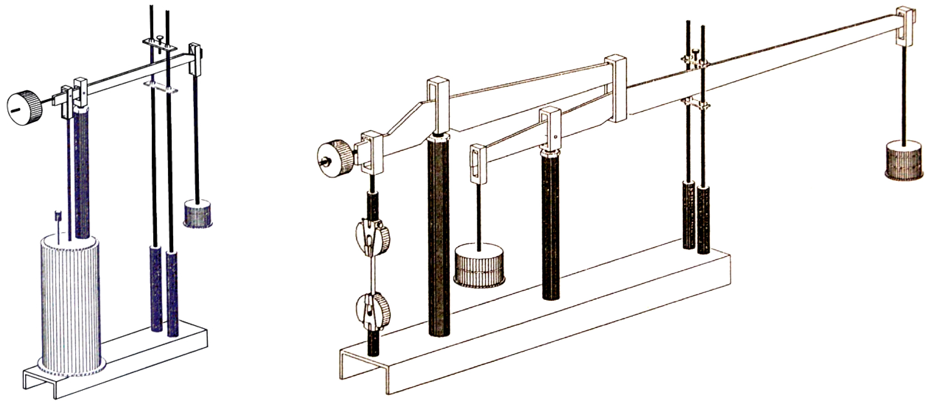
3.2. Experimental Background

The following describes the facility used to obtain experimental data giving useful results in the modeling performed. There were fifteen single-loop test stations and seven double-loop test stations with slope ratios of 10:1 and 25:1, respectively (Figure 1), in the creep testing facility employed in this study (see [14]). Under computer control, testing can be performed concurrently at all stations. While the latter have a robust working capacity of 30 kN, each lever station has a maximum working load capacity of 6 kN. The loading lever mechanism has three bearing locations. In essence, when the initial position is altered, all of these positions need to align in order to preserve a constant leverage ratio. To reduce friction, caution must also be used when selecting the type of bearing. Electronically, the samples’ load level is ascertained. The axial load on the test piece can be linked to the lever’s bending through the Wheatstone bridge’s output when a single-lever station is used, for instance, and strain gauges are positioned to form a complete bridge. To perform the measurements, we used common bonded strain gauges and a Hottinger Baldwin Messtechnik Quantum X data acquisition system.
To experimentally assess how a viscoelastic material responds to prolonged stress circumstances, numerous specimens may need to be tested simultaneously under various loading scenarios. Isothermal testing of a number of previously introduced laminate systems at room temperature and at higher temperatures was part of the current study’s test schedule. Tests of room temperature and humidity were conducted at 23 °C and normal humidity levels. The sophisticated technology in the lab allowed for the consistent performance of creep testing. In experiments, we used [±45]2s laminates. After adjusting and controlling the room’s relative humidity, it was discovered to be within ±5% RH. In experiments, we respected the standards DIN EN ISO 8044 [53] and DIN 50125 [54] (for the dimensions of the specimens).
The material underwent 10 h of laboratory testing to determine material properties like creep compliance. Because of the restricted experimental options, it is almost impossible to forecast the material’s mechanical behavior over longer time periods, like years or even decades, without this information. It is important to perform experiments as accurately as possible since the outcomes of these short-term tests can be used to forecast long-term behavior using a variety of characterization techniques, including the time–temperature overlap principle stated earlier. The strain gauges above the specimen’s neutral axis stretch when the device is loaded, while the gauges below it compress in response to the applied stress. For the two-lever loading method, the applied sample force is measured in a somewhat different but fundamentally comparable way. The strain gauge is held in place on the specimen by two spring clamps, while the initial length is established prior to the test starting. The sample is elongated when the load is applied because the extensometers on the outside of the platelets are compressed and those on the inside are proportionately stretched. The amount of strain induced in the sample can be ascertained by recording the electrical signal known as UB that is produced as a result. As previously noted, extensometers were used to detect Epsilon axial strain, whereas a traditional strain gauge was used to measure Epsilon transverse strain on the ±45 laminates.
The shunt calibration method was used for transverse calibration. This effect need not be taken into consideration in axial strain measurements, in which the strain gauges are connected to create a full bridge circuit. Cylindrical heating chambers were installed in several test stations for testing at higher temperatures. The hot oil is regulated by a thermostat and pumped through a copper coil that circles each chamber. Consequently, the specimen’s cylindrical cavity heats up the chamber around it. The test piece’s temperature was measured using a single thermocouple that was positioned on its surface. It was discovered that the room temperature was kept within a range of roughly ±1 °C. In both cases, it is essential to guarantee that the applied load remains constant and that the specimens experience real axial tensile stress.
Furthermore, the test piece’s produced creep strain is measured electronically. For this, the sample can be directly subjected to conventional sheet resistance extensometers. For more sensitive and precise measurements, this can be achieved by arranging four gauges in a complete bridge or by placing two of these instruments in a half bridge. Both of the aforementioned circuits are somewhat insensitive due to possible inhomogeneities and bending effects. However, the whole bridge design will be more impressive in terms of strain measurement. Precautions must be taken to account for possible temperature changes.
Nevertheless, there are certain drawbacks to measuring strain directly on the sample using strain gauges. Among these include the gauges’ high cost when one is required, their one-time usage, difficulties attaching the gauges to the test component, calibration problems, etc. Extensometers were selected as the measurement method since they are widely usable and exhibit the sensitivity and stability requirements for accurate strain measurements during the testing procedure. This works by converting the elongation of a certain test piece segment, known as the gauge length, into a proportional amount of bending of a thin, elastic steel plate with strain gauge leads attached.
The strain gauge is held in place on the specimen by two spring clamps while the initial length is established prior to the test starting. The sample is elongated when the load is applied because the extensometers on the outside of the platelets are compressed and those on the inside are proportionately stretched. The amount of strain induced in the sample can be ascertained by recording the electrical signal that is produced as a result. As previously indicated, extensometers were used to detect axial strain, while a traditional strain gauge was used to measure transverse strain on the ±45° laminates. The shunt calibration method was used for transverse calibration.
This effect need not be taken into consideration in axial strain measurements, in which the strain gauges are connected to create a full bridge circuit. Cylindrical heating chambers were installed in several test stations for testing at higher temperatures. The hot oil is regulated by a thermostat and pumped through a copper coil that circles each chamber. Consequently, the specimen’s cylindrical cavity heats up the chamber around it. The test piece’s temperature was measured using a single thermocouple that was positioned on its surface. The room temperature was determined to be maintained within ±1 °C.

3.3. Mathematical Model

It is clear that temperature affects creep behavior and material characteristics. Typically, creep is examined independently and at various temperatures. The creep behavior of a viscoelastic material is described by a variety of models in the specialized literature. We shall use the HKK model in this investigation since we believe it better fits our materials based on the history of our experimental work. The starting stress and time after a relationship can be used to express the deformation for this model [50,55]:
ε ( t ) = σ a E 0 + σ a E 1 1 e E 1 η t
The initial elastic modulus E 0 , the elastic modulus E 1 , and the viscosity η of Kelvin dashpots are all related in this equation. This dependence will be ascertained for epoxy composites reinforced with carbon fiber in the following. Temperature and time will affect the composite material’s stress. An expression under the form
ε ( t , T ) = σ a E 0 + σ a E 1 1 e E 1 η t f ( T )
is proposed to describe this dependency. When analyzing the shape of the experimentally determined curves for this dependence, you it can be seen that it is not linear in any case. It is evident that this representation does not show a linear behavior if the empirically measured curves are determined. It will be considered a dependence in the form of a third-degree polynomial:
f ( T ) = α + β T + γ ( T ) 2 + λ ( T ) 3 .
In this case, Equation (15) becomes
ε ( t , T ) = σ a E 0 + σ a E 1 e E η t α + β T + γ ( T ) 2 + λ ( T ) 3 .
If comparing the experimental values made for the strain at different temperatures and times, with the exact theoretical formula (17) that exists, considering the RVE as an isotropic transverse body, between the two there exists a deviation obtained with the following relation:
δ k . i = ε ( t k , T i ) σ a E 0 + σ a E 1 1 e E 1 η t k α + β T + γ ( T ) 2 + λ ( T ) 3 .
In order to bring the suggested estimator function as close to the experimental data as possible, the goal is to identify the coefficients, α , β , γ , and λ , using the experimental results obtained by authors. The method of least squares is a frequently employed technique to obtain good estimators. In our case, for the load scenario under consideration, the total squared deviation is
δ 2 = i = 1 m k = 1 n δ k , i 2 = i = 1 m k = 1 n ε ( t k ) σ a E 0 + σ a E 1 1 e E 1 η t α + β T + γ ( T ) 2 + λ ( T ) 3 2 , = i = 1 m k = 1 n ε ( t k ) s a k α + β T + γ ( T ) 2 + λ ( T ) 3 2 ,
where
s a k = σ a E 0 + σ a E 1 1 e E 1 η t k ,
The mathematical analysis’s procedures provide the conditions that this squared deviation is minimum for the set of coefficients, α , β , γ , and λ , expressed by the following relations:
δ 2 α = 2 i = 1 m k = 1 n ε ( t k ) s a k α + β T + γ ( T ) 2 + λ ( T ) 3 s a k = 0 ,
δ 2 β = 2 i = 1 m k = 1 n ε ( t k ) s a k α + β T + γ ( T ) 2 + λ ( T ) 3 s a k T i = 0 ,
δ 2 γ = 2 k = 1 n ε ( t k ) s a k α + β T + γ ( T ) 2 + λ ( T ) 3 s a k T i 2 = 0 ,
δ 2 λ = 2 k = 1 n ε ( t k ) s a k α + β T + γ ( T ) 2 + λ ( T ) 3 s a k T i 3 = 0 ,
The system (21)–(24) obtained after performing the calculus is a linear system of four equations with four unknowns. We will use the following notations:
b 1 = i = 1 m k = 1 n ε ( t k ) s a k ;   b 2 = i = 1 m k = 1 n ε ( t k ) s a k T i ;
b 3 = i = 1 m k = 1 n ε ( t k ) s a k T i 2 ;   b 4 = i = 1 m k = 1 n ε ( t k ) s a k T i 3 ;
c T 0 = i = 1 m k = 1 n s a k 2 ; c T 1 = i = 1 m k = 1 n s a k 2 T i ; c T 2 = i = 1 m k = 1 n s a k 2 T i ;
c T 3 = i = 1 m k = 1 n s a k 2 T i 3 ; c T 4 = i = 1 m k = 1 n s a k 2 T i 4 ;
c T 5 = i = 1 m k = 1 n s a k 2 T i 5 ; c T 6 = i = 1 m k = 1 n s a k 2 T i 6 .
So, Equations (21)–(24) become
α c T 0 + β c T 1 + γ c T 2 + λ c T 3 = b 1 ; α c T 1 + β c T 2 + γ c T 3 + λ c T 4 = b 2 ; α c T 2 + β c T 3 + γ c T 4 + λ c T 5 = b 3 ; α c T 3 + β c T 4 + γ c T 5 + λ c T 6 = b 4 ;
which offers us the solution α , β , γ , λ .

4. Results

4.1. Material and Specimens

The fiber-reinforced materials under investigation were composites that were sold commercially. The material (resin) used for experiment was a Fibredux 6376 (known as HexPly® 6376). This is a high-performance epoxy resin matrix (Hexcel Corporation, Stamford, CT, USA) used mainly for manufacturing primary aircraft structures. The material has a lot of useful properties, such as excellent toughness, damage tolerance, and strong suitability for high-temperature engineering applications. Another property that recommends the use of the material is the high impact resistance, enhancing the durability of the composite structure. This resin maintains good properties up to 150 °C. Other useful mechanical properties of this material are presented in Table 1.
So, a hardened epoxy resin with a glass transition temperature of roughly 180 °C serves as the prepreg system’s matrix. The laminates were produced using conventional procedures. The epoxy system’s laminates were autoclaved for an hour at 180 °C to cure them, and then they were postcured for six hours at 190 °C. The cast panels quality was controlled with the aid of ultrasonic scanning. The fiber volume content was 60% ± 3%. The fiber-reinforced specimens had nominal measurements of 150 mm in length, 10 mm in width, and 1 mm in thickness. It should be mentioned that the specimens were stored in chambers filled with desiccant after they were made. During storage before testing, the specimens had to be shielded from unnecessary moisture absorption. It was discovered that the rooms’ relative humidity was about 35%.
As mentioned before, both normal and increased temperatures (23 °C) were used for isothermal creep studies. Each CREEP test took ten hours to load. The experiments were conducted at temperatures below the glass transition temperatures. The highest test temperature was roughly 20 °C lower than epoxy resin’s glass transition temperature. For the reinforced material, the epoxy resin was tested at 23 °C, 80 °C, 120 °C, and 140 °C. At room temperature, four stress levels ranging from 10% to 70% of the ultimate tensile stress were applied. To guarantee consistent temperature distribution in the sample and the chamber, tests were started an hour after the goal test temperature was obtained in the chamber. Temperature, load, and creep stresses were recorded at suitable intervals throughout the experiment. As required by current standards, these samples must be maintained in a temperature-controlled room for twenty minutes prior to testing in order to ensure that the experimental temperature is reached.

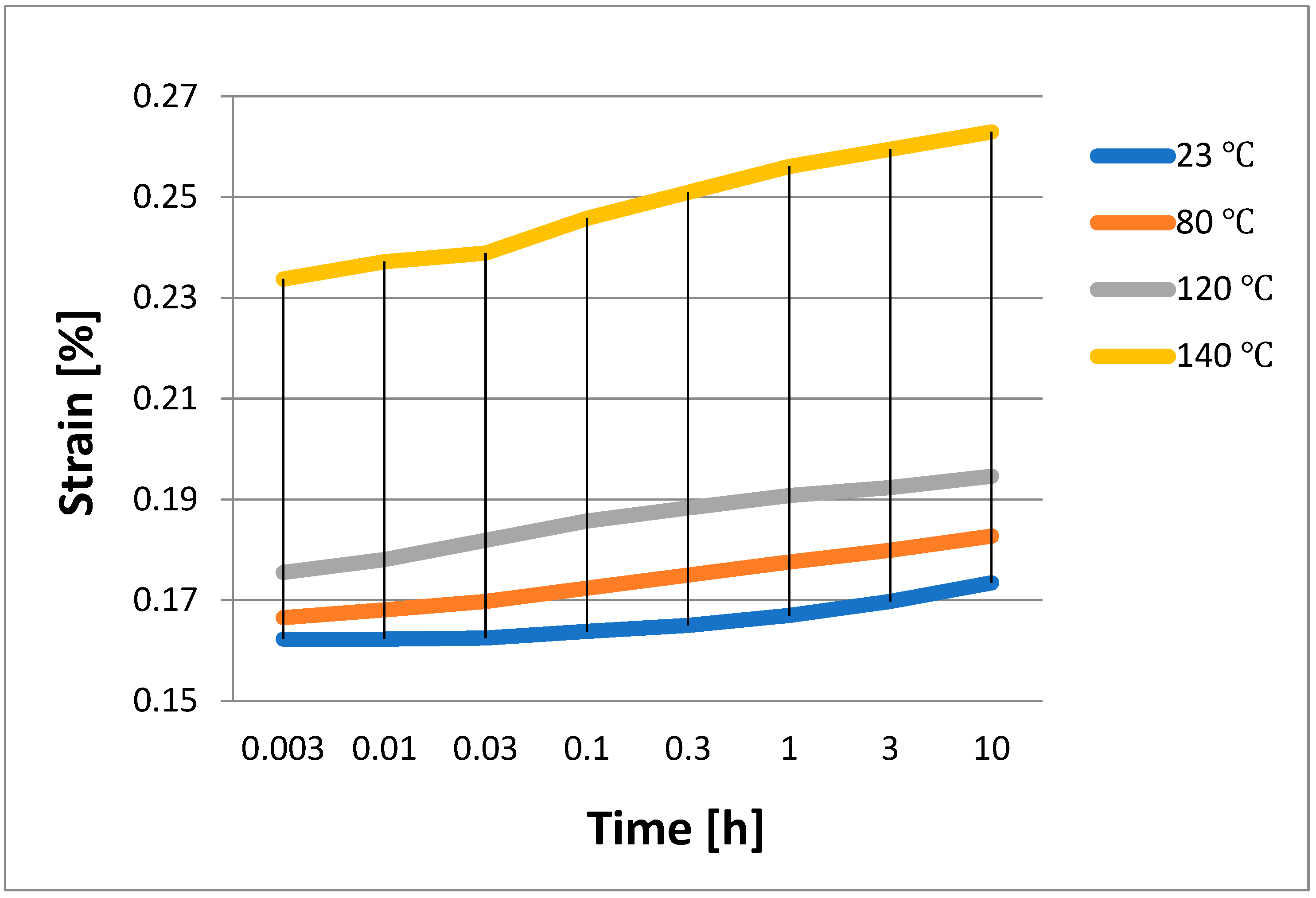
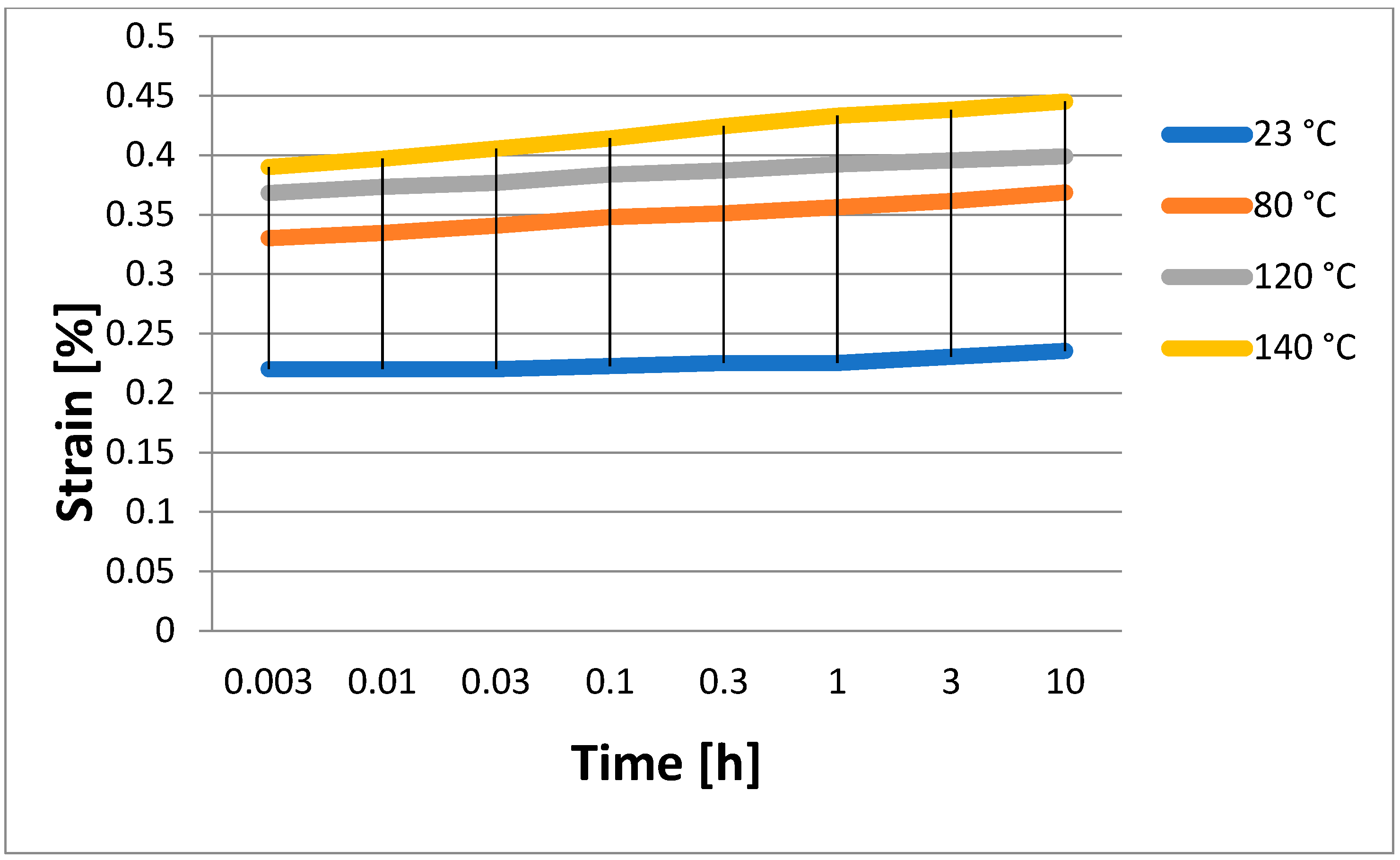
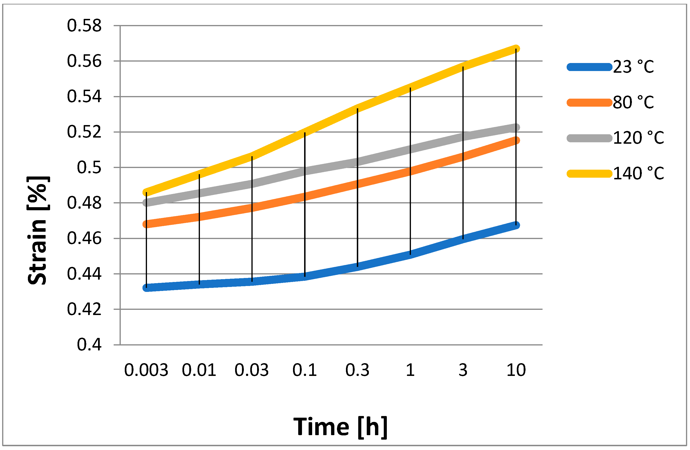
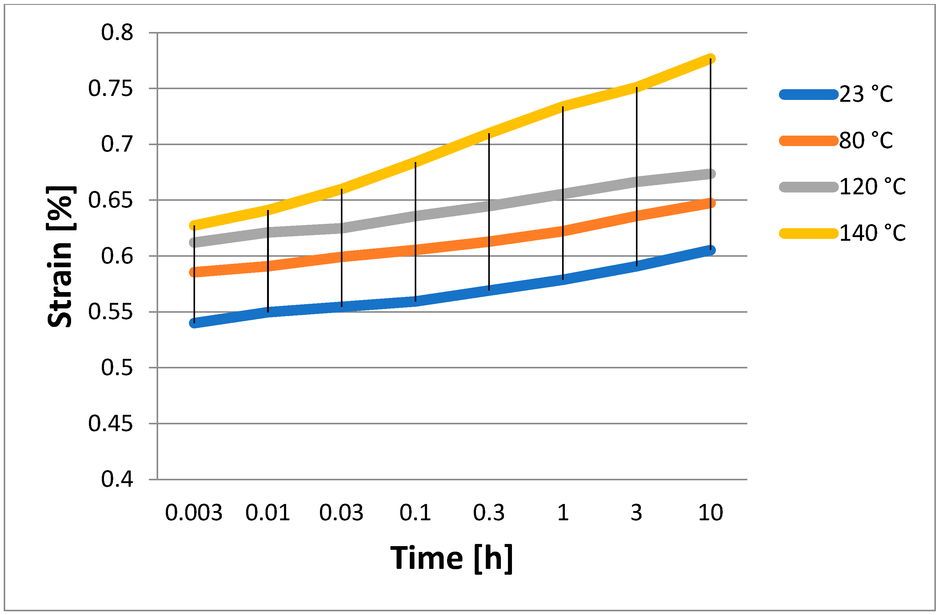
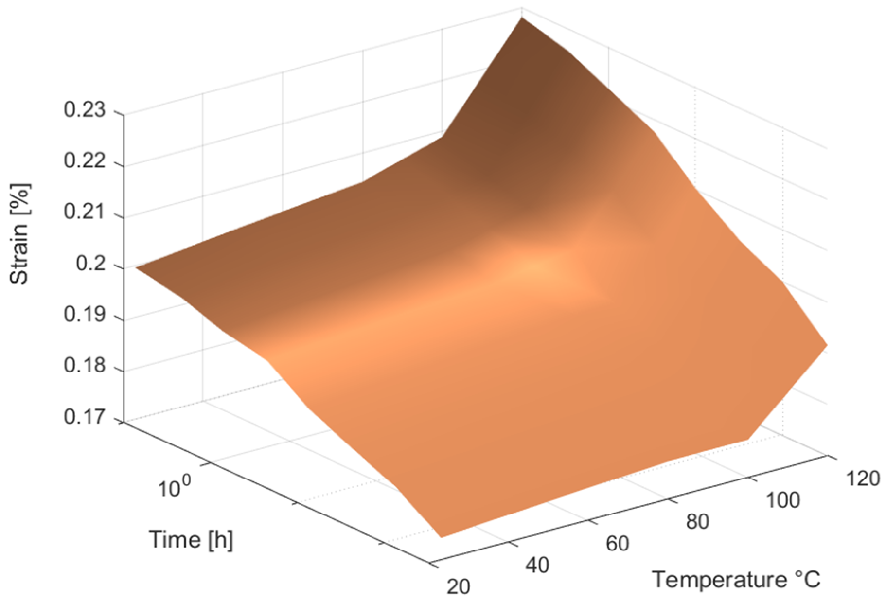
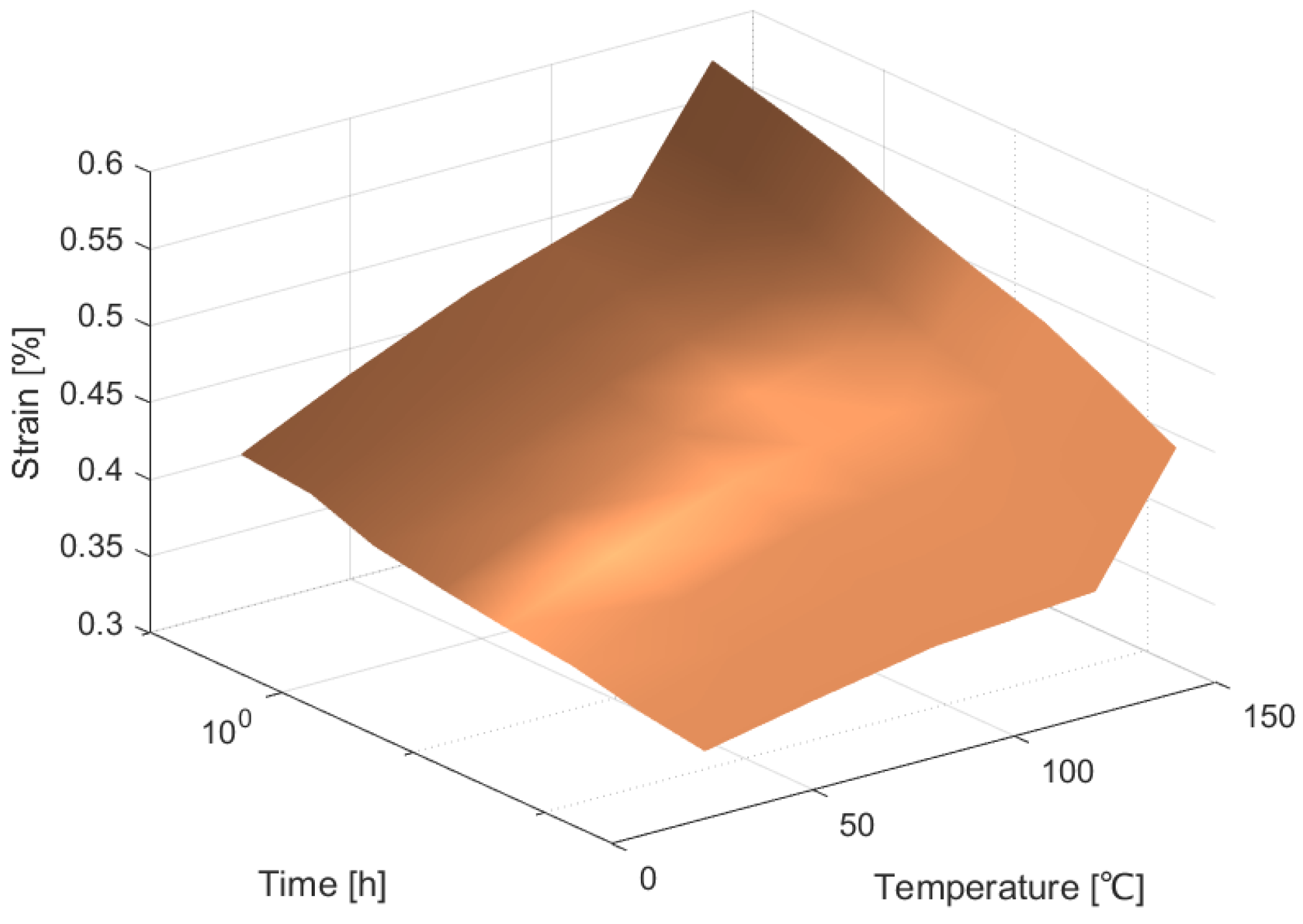
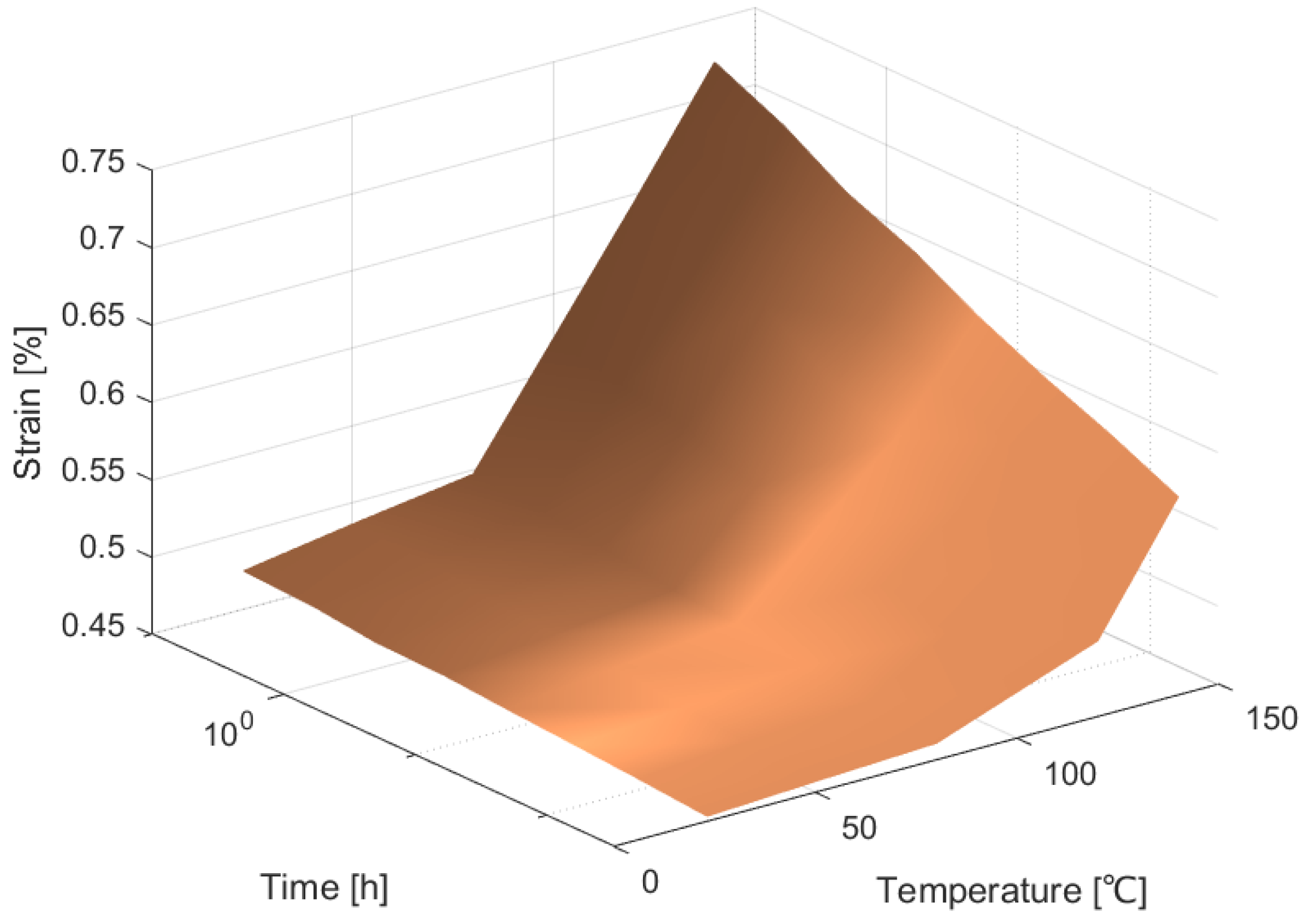
4.2. Results of Measurements

Strain measurements were obtained using the above-mentioned samples and the apparatus outlined in Section 3.2, taking into account various beginning loading scenarios and altering the test temperature. Thus, the graphs shown in Figure 2, Figure 3, Figure 4 and Figure 5 were produced. These results show the data that were then used to apply the least squares approach to find the polynomial coefficients. They were ascertained by measuring the strain that the epoxy/carbon composite samples produced. Four distinct loading scenarios were used to prestress the samples: 14 MPa, 29 MPa, 36 MPa, and 44 MPa. Four distinct temperatures were used for the measurements: 23 °C (the temperature inside the lab), 80 °C, 120 °C, and 140 °C.
Finding an interpolator that would provide us with the material’s behavior dependent on temperature was the challenge we set for ourselves in this effort. Different values of these interpolations were found for each of the beginning loading scenarios, of 14 MPa, 29 MPa, 36 MPa, and 44 MPa. Finding an interpolator that would provide us with an analytical relationship taking the original stress into account was not an issue in the current work. Consequently, four distinct starting loading scenarios were subjected to numerical analysis. The coefficients corresponding to the interpolator were derived from the previously provided formulas.
Figure 6, Figure 7, Figure 8 and Figure 9 shows the graphs for the functions that were obtained. These yielded good interpolators for estimating the behavior of the examined polymer as it varies with temperature. These figures are merged in Figure 10.
In Figure 11, we present a comparison between the experimental values and the interpolated curve.

5. Discussion

It is possible to make some inferences from the stated trials. It is noteworthy that longitudinal deformation is predominantly a fiber-dominated feature in a unidirectional composite, whereas shear and transverse deformations are primarily matrix-dependent. In other words, uniaxial tension testing on a 0° specimen can be used to identify the constant components S 11 and S 12 in the compliance matrix. Since the fibers are substantially stiffer than the matrix, the fiber property largely controls the response of a lamina in the fiber direction S 12 = ν 12 S 11 , where ν 12 is the major Poisson’s ratio, and S 11 , or compliance along the fiber direction, is considered to be time-independent.
Consequently, as the material extends under the specified load, some of the stress is transferred to the fiber and matrix. Because the fibers are elastic and do not creep, the material experiences stress relaxation, which stops the viscoelastic matrix from creeping. This creates a little secondary strain, which is often interpreted as creep, as part of the load is passed to the fibers. These behaviors are known as “relaxation creep” and are essentially dependent on the fiber reaction. In contrast, 90 °C produces the compliance S 22 . Nevertheless, this characteristic is matrix-dominated due to its close connection to the matrix response.

6. Conclusions

The creep behavior of a composite material with unidirectional fibers may be accurately estimated using the model presented in the paper. The findings of the interpolation are based on experiments in the laboratory. The approach provides a straightforward tool for examining how mechanical qualities change with temperature. This makes it possible to perform research on the creep behavior of composite materials with unidirectional carbon fibers. The authors’ laboratory data serve as the foundation for the suggested approach. High-temperature experiments reveal a large reduction in strength, which designers need to consider. These research findings have importance for various real-world applications. The interpolation proposed seems to be effective. The results obtained, as shown in Figure 11, certify that this kind of interpolation can be very simple to execute. The differences for this case are less than 1%.
The properties of the material under study are provided in the results we obtained, and these parameters can be used in the engineering of composite structures.

Author Contributions

Conceptualization, M.K. and S.V.; methodology, M.K. and S.V.; software, M.K. and S.V.; validation, M.K. and S.V.; formal analysis, M.K. and S.V.; investigation, M.K. and S.V.; resources, M.K. and S.V.; data curation, M.K. and S.V.; writing—original draft preparation, M.K. and S.V.; writing—review and editing, M.K. and S.V.; visualization, M.K. and S.V.; supervision, M.K. and S.V.; project administration, M.K. and S.V.; funding acquisition, M.K. and S.V. All authors have read and agreed to the published version of the manuscript.

Funding

The APC was funded by Transylvania University of Brasov (HBS2020/4328).

Institutional Review Board Statement

Not applicable.

Informed Consent Statement

Not applicable.

Data Availability Statement

The original contributions presented in this study are included in the article. Further inquiries can be directed to the corresponding author.

Conflicts of Interest

The authors declare no conflicts of interest.

References

  1. Available online: www.hexcel.com (accessed on 5 March 2025).
  2. Available online: https://www.knowde.com/ (accessed on 5 March 2025).
  3. ISO R527; Plastics—Determination of Tensile Properties. ISO: Geneva, Switzerland, 1966.
  4. ISO 178; Plastics—Determination of Flexural Properties. ISO: Geneva, Switzerland, 2019.
  5. Li, M.Z.; Jia, X.Y.; Han, Y.C.; Gao, L.H.; Ma, Z. Investigation of damage mechanisms in carbon fiber epoxy resin composites under laser irradiation. Polym. Compos. 2025. early access. [Google Scholar]
  6. Yu, B.S.; Zhang, Y.W.; Liu, Y.; Jin, Y.W.; Song, Y.H.; Peng, M. Enhancing the mechanical properties of carbon fiber/epoxy resin laminates through a combination of carbon fiber coating and matrix reinforcement with an aminated para-polyamide. Compos. Part A Appl. Sci. Manuf. 2025, 191, 108740. [Google Scholar]
  7. Donda, G.M.; Ortega, F.D.; Xavier, G.D.; Lima, J.V.F.; Ricardo, F.V.; Passador, F.R.; de Oliveira, I.R. Effects of graphene nanoplatelets dispersion on the mechanical properties of epoxy resin and carbon fiber laminated composites. J. Compos. Mater. 2025. early access. [Google Scholar]
  8. Lu, J.J.; Zheng, C.X.; Wang, L.; Dai, Y.C.; Wang, Z.Y.; Song, Z.B. T700 Carbon Fiber/Epoxy Resin Composite Material Hygrothermal Aging Model. Materials 2025, 18, 369. [Google Scholar] [CrossRef]
  9. Duan, X.; Yuan, H.; Tang, W.; He, J.; Guan, X. A General Temperature-Dependent Stress–Strain Constitutive Model for Polymer-Bonded Composite Materials. Polymers 2021, 13, 1393. [Google Scholar] [CrossRef]
  10. Luo, L.; Luo, Q.; Zhang, G.; Li, Q.; Sun, G. On strain rate and temperature dependent mechanical properties and constitutive models for additively manufactured polylactic acid (PLA) materials. Thin-Walled Struct. 2022, 179, 109624. [Google Scholar] [CrossRef]
  11. Erartsin, O.; van Drongelen, M.; Govaert, L.E. Identification of plasticity-controlled creep and fatigue failure mechanisms in transversely loaded unidirectional thermoplastic composites. J. Compos. Mater. 2021, 55, 1947–1965. [Google Scholar] [CrossRef]
  12. Schapery, R.A. Stress Analysis of Viscoelastic Composite Materials. J. Compos. Mater. 1967, 1, 228. [Google Scholar]
  13. Jamshidi, M.; Shokrieh, M.M. On the Schapery nonlinear viscoelastic model: A review. Eur. J. Mech. A-Solids 2024, 108, 105403. [Google Scholar]
  14. Katouzian, M. On the Effect of Temperature on Creep Behavior of Neat and Carbon Fiber Reinforced PEEK and Epoxy—A micromechanical Approach. Ph.D. Thesis, Dresden University of Technology, Dresden, Germany, 1995. [Google Scholar]
  15. Kovacevic, D.; Sundararajan, B.K.; van der Meer, F.P. Micromechanical model for off-axis creep rupture in unidirectional composites undergoing finite strains. Compos. Part A Appl. Sci. Manuf. 2024, 176, 107860. [Google Scholar]
  16. Ha, S.K.; Wang, Q.L.; Chang, F.K. Modeling the Viscoplastic Behavior of Fiber-Reinforced Thermoplastic Matrix Composites at Elevated Temperatures. J. Compos. Mater. 1991, 25, 334–374. [Google Scholar] [CrossRef]
  17. Katouzian, M.; Bruller, O.S.; Horoschenkoff, A. On the Effect of Temperature on the Creep-Behavior of Neat and Carbon-Fiber-Reinforced PEEK and Epoxy-Resin. J. Compos. Mater. 1995, 29, 372–387. [Google Scholar] [CrossRef]
  18. Niculiţă, C.; Vlase, S.; Bencze, A.; Mihălcică, M.; Calin, M.R.; Serbina, L. Optimum stacking in a multi-ply laminate used for the skin of adaptive wings. Optoelectron. Adv. Mater.—Rapid Commun. 2011, 5, 1233–1236. [Google Scholar]
  19. Yadav, A.K.; Carrera, E.; Marin, M.; Othman, M.I. Reflection of hygrothermal waves in a Nonlocal Theory of coupled thermo-elasticity. Mech. Adv. Mater. Struct. 2024, 31, 1083–1096. [Google Scholar] [CrossRef]
  20. Marin, M.; Abbas, I.; Kumar, R. Relaxed Saint-Venant principle for thermoelastic micropolar diffusion. Struct. Eng. Mech. 2014, 51, 651–662. [Google Scholar] [CrossRef]
  21. Teodorescu-Draghicescu, H.; Vlase, S. Homogenization and averaging methods to predict elastic properties of pre-impregnated composite materials. Comput. Mater. Sci. 2011, 50, 1310–1314. [Google Scholar] [CrossRef]
  22. Vlase, S.; Teodorescu-Draghicescu, H.; Serbina, L. Simulation of the elastic properties of some fiber-reinforced composite laminates under off-axis loading system. Optoelectron. Adv. Mater.—Rapid Commun. 2011, 5, 424–429. [Google Scholar]
  23. Vlase, S.; Teodorescu-Draghicescu, H.; Calin, M.R. Behavior of multiphase fiber-reinforced polymers under short time cyclic loading. Optoelectron. Adv. Mater.—Rapid Commun. 2011, 5, 419–423. [Google Scholar]
  24. Teodorescu-Draghicescu, H.; Vlase, S.; Mihalcica, M. Advanced Pultruded Glass Fibers-Reinforced Isophthalic Polyester Resin. Plast. Mater. 2015, 52, 62–64. [Google Scholar]
  25. Ribeiro, B.; Botelho, E.C.; Costa, M.L.; Bandeira, C.F. Carbon nanotube bucky paper reinforced polymer composites: A review. Polymers 2017, 27, 247–255. [Google Scholar]
  26. Li, Y.L.; Chen, W.J.; Shen, M.Y.; Chiang, C.L.; Yip, M.C. Study on the Mechanical Properties and Creep Behaviour of Carbon Fiber Nano-Composites. International Conference on Advanced Engineering Materials and Technology (AEMT2011). Mater. Des. 2011, 284–286, 557–564. [Google Scholar]
  27. Daei-Sorkhabi, A.H.; Hosseinzadeh-Nodehi, S.F. Numerical study of the effect of carbon fiber/epoxy resin adhesive thickness on the creep behaviour of carbon steel plate joints. J. Adhes. Sci. Technol. 2019, 33, 1790–1805. [Google Scholar] [CrossRef]
  28. Nakada, M.; Miyano, Y.; Kageta, S.; Nishida, H.; Hayashi, Y.; Uzawa, K. Prediction of statistical life time for unidirectional CFRTP under cyclic loading. J. Reinf. Plast. Compos. 2021, 40, 749–758. [Google Scholar] [CrossRef]
  29. Gordelier, T.J.; Thies, P.R.; Turner, L.; Johanning, L. Optimizing the FDM additive manufacturing process to achieve maximum tensile strength: A state-of-the-art review. Rapid Prototyp. J. 2019, 25, 953–971. [Google Scholar] [CrossRef]
  30. Fairhurst, A.; Thommen, M.; Rytka, C. Comparison of short and long term creep testing in high performance polymers. Polym. Test. 2019, 78, 105979. [Google Scholar] [CrossRef]
  31. Vlase, S.; Teodorescu-Draghicescu, H.; Scutaru, M.L. Advanced Polylite composite laminate material behavior to tensile stress on weft direction. J. Optoelectron. Adv. Mater. 2012, 14, 658–663. [Google Scholar]
  32. Fujiwara, T.; Takeuchi, M.; Daoyuan, C.; Liang, Y.; Nishioka, N.; Okayasu, M. Mechanical Properties of Epoxy- and Dicyclopentadiene-Based Carbon-Fiber-Reinforced Plastics at Low and Room Temperatures. Appl. Compos. Mater. 2025. early access. [Google Scholar] [CrossRef]
  33. Kazanci, M. Carbon fiber reinforced microcomposites in two different epoxies. Polym. Test. 2004, 23, 747–753. [Google Scholar] [CrossRef]
  34. Battawi, A.A.; Abed, B.H.; Al-Filfily, A.A.H. Enhancements of Creep Compliance of Kevlar and Carbon Fibers Reinforced Sika Epoxy Composites. Rev. Des Compos. Des Mater. Av.-J. Compos. Adv. Mater. 2024, 34, 593–602. [Google Scholar] [CrossRef]
  35. Tan, H.; Yan, S.; Zhu, S.; Wen, P. Creep Modeling of Composite Materials Based on Improved Gene Expression Programming. Sci. Rep. 2022, 12, 22244. [Google Scholar] [CrossRef]
  36. Griffith, W.I. The Accelerated Characterization of Viscoelastic Composite Materials. Ph.D. Thesis, VPI & SU, Blacksburg, VA, USA, 1978. [Google Scholar]
  37. Yeow, Y.T. The Temperature Behavior of Graphite Epoxy Laminates. Ph.D. Thesis, VPI & SU, Blacksburg, VA, USA, 1978. [Google Scholar]
  38. Sturgeon, J.B. Creep of Fiber Reinforced Thermosetting Resins. In Creep of Engineering Materials; Pomeroy, C.D., Ed.; Mechanical Engineering Publications Ltd.: London, UK, 1978. [Google Scholar]
  39. Miyano, Y.; Nakada, M.; Morisawa, Y.; Matsuno, J.; Kageta, S. Prediction of creep failure life for unidirectional CFRP with heat-resistant epoxy resin as matrix exposed to high temperature under tension load. J. Compos. Mater. 2024, 58, 1051–1062. [Google Scholar] [CrossRef]
  40. Yang, J.Y.; Ma, X.F.; Wang, H.; Shang, F.L.; Hou, D.M. Long-term creep deformation of carbon fiber/epoxy composites with physical aging: Experimental investigation and constitutive modeling. Polym. Compos. 2024, 45, 2825–2840. [Google Scholar] [CrossRef]
  41. Santos, P.; Silva, A.P.; Reis, P. Effect of carbon nanofibers on the viscoelastic response of carbon/epoxy composites. J. Reinf. Plast. Compos. 2023, 43, 1257–1271. [Google Scholar] [CrossRef]
  42. Cha, J.; Yoon, S. Long-term viscoelastic properties of carbon fiber/epoxy composites using tow prepreg strand specimens. Adv. Compos. Mater. 2004, 33, 151–161. [Google Scholar] [CrossRef]
  43. Nakada, M.; Miyano, Y.; Nonaka, T.; Morisawa, Y.; Isaki, T.; Hirano, T.; Uzawa, K. Statistical tensile and flexural fatigue lives of unidirectional CF/PP laminates. J. Reinf. Plast. Compos. 2024, 43, 195–204. [Google Scholar] [CrossRef]
  44. Katouzian, M.; Vlase, S.; Scutaru, M.L. Finite Element Method-Based Simulation Creep Behavior of Viscoelastic Carbon-Fiber Composite. Polymers 2021, 13, 1017. [Google Scholar] [CrossRef]
  45. Monticeli, F.M.; Ornaghi, H.L.; Neves, R.M.; Cioffi, M.O.H. Creep/recovery and stress-relaxation tests applied in a standardized carbon fiber/epoxy composite: Design of experiment approach. J. Od Strain Anal. Eng. Des. 2021, 55, 109–117. [Google Scholar] [CrossRef]
  46. Emara, M.; Torres, L.; Baena, M.; Bards, C.; Moawad, M. Effect of sustained loading and environmental conditions on the creep behavior of an epoxy adhesive for concrete structures strengthened with CFRP laminates. Compos. Part B-Eng. 2017, 129, 88–96. [Google Scholar] [CrossRef]
  47. Raghavan, J.; Meshii, M. Activation Theory for Creep of Matrix Resin and Carbon-Fiber-Reinforced Polymer Composite. J. Mater. Sci. 1994, 29, 5078–5084. [Google Scholar] [CrossRef]
  48. Raghavan, J.; Meshii, M. Prediction of Creep-Rupture of Unidirectional Carbon-Fiber-Reinforced Polymer Composite. Mater. Sci. Eng. A Struct. Mater. Prop. Microstruct. Process. 1995, 197, 237–249. [Google Scholar] [CrossRef]
  49. Blassiau, S.; Thionnet, A.; Bunsell, A.R. Micromechanisms of load transfer in a unidirectional carbon fibre-reinforced epoxy composite due to fibre failures. Part 2: Influence of viscoelastic and plastic matrices on the mechanisms of load transfer. Compos. Struct. 2006, 74, 319–331. [Google Scholar] [CrossRef]
  50. Callister, W.D., Jr.; Rethwisch, D.G. Materials Science and Engineering: An Introduction; Wiley: Hoboken, NJ, USA, 2020. [Google Scholar]
  51. Fung, Y.C. Fundamentals of Solid Mechanics; Prentice-Hall: Hoboken, NJ, USA, 1965. [Google Scholar]
  52. Morris, D.H.; Yeow, Y.T.; Brinson, H.F. The Viscoelastic Behavior of the Principal Compliance Matrix of Unidirectional Graphite Epoxy Composite. Polym. Compos. 1980, 1, 32–36. [Google Scholar] [CrossRef]
  53. DIN EN ISO 8044; Corrosion of Metals and Alloys—Vocabulary. European Standards: Plzen, Czech Republic, 2024. Available online: https://www.iso.org/standard/83222.html (accessed on 11 March 2025).
  54. DIN 50125; Testing of Metallic Materials—Tensile Test Pieces. European Standards: Plzen, Czech Republic, 2022. Available online: https://www.en-standard.eu/din-50125-testing-of-metallic-materials-tensile-test-pieces (accessed on 11 March 2025).
  55. Hua, T.; Sirong, Z.; Shilin, Y.; Pin, W. Predictive Model for Creep Behavior of Composite Materials Using Gene Expression Programming. Appl. Compos. Mater. 2023, 30, 1003–1030. [Google Scholar] [CrossRef]
Figure 1. The single-loop test station and double-loop test station.
Applsci 15 04206 g001
Figure 2. Strain obtained experimentally for an initial stress of 14 MPa.
Applsci 15 04206 g002
Figure 3. Strain obtained experimentally for an initial stress of 29 MPa.
Applsci 15 04206 g003
Figure 4. Strain obtained experimentally for an initial stress of 36 MPa.
Applsci 15 04206 g004
Figure 5. Strain obtained experimentally for an initial stress of 44 MPa.
Applsci 15 04206 g005
Figure 6. Representation of creep behavior of PEEK/carbon composite depending on temperature and time at the initial stress of 14 MPa.
Applsci 15 04206 g006
Figure 7. Representation of creep behavior of PEEK/carbon composite depending on temperature and time at the initial stress of 29 MPa.
Applsci 15 04206 g007
Figure 8. Representation of creep behavior of PEEK/carbon composite depending on temperature and time at the initial stress of 36 MPa.
Applsci 15 04206 g008
Figure 9. Representation of creep behavior of PEEK/carbon composite depending on temperature and time at the initial stress of 44 MPa.
Applsci 15 04206 g009
Figure 10. Representation of creep behavior of PEEK/carbon composite at the initial stresses of 14, 29, 36, and 44 MPa.
Applsci 15 04206 g010
Figure 11. Representation of creep behavior of PEEK/carbon composite at the initial stress of 44 MPa. Experimental values are shown and values obtained by interpolation.
Applsci 15 04206 g011
Table 1. Mechanical properties of the material.
Nr.PropertyValue
1Tensile Strength105 MPa
2Tensile Modulus3.60 GPa
3Flexural Strength144 MPa
4Flexural Modulus4.4 GPa
5Toughness (G1C)432 J/m
Disclaimer/Publisher’s Note: The statements, opinions and data contained in all publications are solely those of the individual author(s) and contributor(s) and not of MDPI and/or the editor(s). MDPI and/or the editor(s) disclaim responsibility for any injury to people or property resulting from any ideas, methods, instructions or products referred to in the content.

