Article

Mechanical Research and Optimization of the Design of an Umbrella-Shaped Enlarged-Head Hollow Grouting Bolt with an Expansion Pipe

by
Jiang Xiao
1,2,
Tongxiaoyu Wang
1,2,*,
Youyun Li
3,
Yulin Wang
1,2,
Yujiang Liu
1,2,
Boyuan Zhang
1,2,
Yihui Wang
1,2 and
Yufeng Guo
1,2
1
College of Energy Engineering, Xi ’an University of Science and Technology, Xi’an 710054, China
2
Key Laboratory of Mine Mining and Disaster Prevention in West China, Ministry of Education, Xi’an University of Science and Technology, Xi’an 710054, China
3
College of Highway, Chang’an University, Xi’an 710061, China
*
Author to whom correspondence should be addressed.
Appl. Sci. 2025, 15(8), 4182; https://doi.org/10.3390/app15084182
Submission received: 11 March 2025 / Revised: 7 April 2025 / Accepted: 9 April 2025 / Published: 10 April 2025
(This article belongs to the Special Issue Progress and Challenges of Rock Engineering)

Abstract

:
In geotechnical engineering, traditional anchor bolts often have problems such as an insufficient bearing capacity, their ease of loosening, and an unsatisfactory support effect under complex geological conditions (such as soft soil or broken surrounding rock), resulting in it being difficult to guarantee engineering stability. In order to solve these problems, this paper studies the supporting performance of a hollow grouting anchor with an umbrella-shaped expansion head with an expansion pipe. Through theoretical analysis, mechanical performance analysis, and experimental analysis, the supporting mechanisms and mechanical characteristics of a hollow grouting anchor with an umbrella-shaped expansion head are systematically discussed. The calculation formula for the maximum pull-out force of the umbrella-shaped expansion head is clarified, and the fixed range of the expansion body section in relation to the loose ring is quantified. Based on the analysis results, the structural parameters and material properties of the bolt were optimized, and the optimization effect was verified by numerical simulation. The results show that the optimized bolt has significantly improved the pull-out bearing capacity, shear resistance, and reinforcement effect on the soil. The maximum pull-out force of the umbrella-shaped expansion head can be increased by up to 35%, and the fixed range of the expansion body section can be expanded by 45%. The research provides an efficient and reliable support solution for geotechnical engineering fields, such as roadway engineering and tunnel engineering, which significantly improves the stability and safety of engineering under complex geological conditions. At the same time, it provides an important theoretical basis and practical reference for the design and construction of similar projects.

1. Introduction

As one of the key technologies in the field of geotechnical engineering, the bolt support system plays an irreplaceable role in the support of roadway and tunnel engineering. Its application has spread all over the world and achieved remarkable engineering results. In terms of mechanical mechanisms, geotechnical anchoring technology realizes the synergistic effect of a supporting system and the surrounding rock medium by optimizing the distribution of the soil stress field, thus significantly improving the structural integrity and overall stability of the rock and soil [1]. This technology not only reflects the transformation of modern geotechnical engineering from passive support to active reinforcement, but it also provides reliable technical support for underground engineering under complex geological conditions. Under the unfavorable geological conditions such as a soft clay layer and a loose sedimentary layer, or in an engineering environment with high requirements for the deformation control of rock and soil mass, the effect of the application of a traditional grouting bolt in roadway and tunnel support reinforcement is significantly limited. The specific performance is as follows: the overall deformation of the bolt exceeds the allowable range, the structural bearing capacity is insufficient, and the waterproof performance is poor. These limitations not only affect the reliability of the supporting structure but also pose a potential threat to the safety of the project, which needs to be solved through technological innovation. However, a large number of experimental data and theoretical studies [2,3,4,5,6] show that there is an obvious nonlinear relationship between the ultimate bearing capacity of ordinary anchors and the length of the anchorage section; with an increase in the length of the anchorage section, the bearing capacity increases rapidly and then tends to be stable. This phenomenon shows that the method of increasing the bearing capacity only by extending the length of the anchorage section has an obvious diminishing effect, and it is difficult to fundamentally solve the technical problem of an insufficient bearing capacity. With the rapid development of material science and geotechnical engineering technology, the bolt support system has shown a significant diversified development trend. Based on different engineering requirements and technical parameters, a modern bolt system can be systematically divided according to multiple classification criteria: from the perspective of the anchoring mechanism, it can be divided into grouting type and friction type; according to the type of grouting material, it can be divided into cement-based and resin-based categories; according to the material properties of the rod body, it can be divided into traditional steel and new polymer composite materials. The prestressing method can be divided into active support and passive support systems; in addition, it can also be divided into special supporting structures, such as conventional anchors and energy-absorbing anchors, based on the energy dissipation characteristics [7,8,9,10,11,12,13]. This diversified technical development not only enriches the theoretical system of bolt support but also provides reliable technical support for precise support under complex engineering conditions.
At the same time, through systematic research, scholars at home and abroad have innovatively proposed the new supporting structure of an expanded head bolt and developed and applied it [14]. An enlarged head bolt is a support technology that expands the diameter of the bottom of the borehole through a specific process and forms an end expansion structure with a diameter significantly larger than the rod body after grouting. This technology significantly improves the uplift bearing capacity of the bolt by increasing the contact area between the anchoring end and the rock and soil mass. The experimental data show that compared with the traditional equal diameter bolt, the ultimate bearing capacity of the enlarged head bolt can be increased by 20% to 30%, and the bearing capacity can be increased by 60% under some optimized design conditions [15]. By optimizing the geometric shape of the end of the anchor rod the redistribution of the stress field is realized, which provides a new solution to effectively solve the key technical problems such as an insufficient bearing capacity and the difficult deformation control of traditional anchor rods. Taiwanese scholars Shih-Tsung Hsu et al. [16] pointed out in their research that an expansion bolt with a cylindrical structure at the bottom is one of the most widely used types of enlarged-head bolts in engineering practice. Chen Haohua et al. [17] proposed an innovative ship-anchored grouting open soil anchor structure, which significantly improved the mechanical properties and engineering applicability of the anchorage system by introducing an anchor claw design. Chen [18] innovatively proposed an umbrella-shaped anti-pulling anchor structure for the technical problem that the grouting method is limited in its application in a non-soft soil layer due to grouting pressure. Zhang Jihong et al. [19] innovatively realized the self-expansion function of the anchorage body by introducing the umbrella-shaped reaction plate structure into the bolt system. Liu Yi et al. [20,21] developed a new type of anti-pulling device by combining an umbrella anchor head and a tension anchor cable, and systematically evaluated its mechanical properties through a series of pull-out tests. In order to further verify the practical application effect of the technology, Mei Guoxiong [22] and Xu Min [23] et al. carried out field tests on the engineering site of the Z2 straight tower of the double-circuit transmission line from Beilun Power Plant to Cangyan in Ningbo, Zhejiang Province. The test results showed that the umbrella anchor shows significant advantages in bearing capacity and has great engineering application potential. Through the combination of theoretical calculation and experimental research, Zhang Si-feng et al. [24] carried out a systematic optimization design study on the enlarged-head bolt. The results show that there are significant differences in the ultimate pull-out force of the enlarged-head bolt with different geometric shapes: the truncated cone-shaped (umbrella-shaped) tension bolt shows the best bearing performance and its ultimate pull-out force is the largest. The ladder-shaped bolt is the second, the semi-elliptical bolt is the third, and the cylindrical bolt has the smallest pull-out force.
Based on the problems of insufficient bearing capacity, and difficult deformation control and limited engineering land in the existing research, combined with the inspiration of previous research results, this paper innovatively combines the umbrella-shaped enlarged-head bolt technology and the grouting bolt anchor cable theory [25,26,27,28,29] with the prestressed diffusion effect of a bolt tail support, and proposes a new umbrella-shaped enlarged-head hollow grouting bolt structure with an expansion pipe. The structure adopts an umbrella-shaped expansion head design at the head of the anchor rod, and an expansion sleeve structure is introduced at the tail. Through double optimization, the contact area between the anchor rod and the rock and soil mass is significantly increased, thereby expanding the support influence range of a single-anchor rod. This design not only optimizes the stress distribution and load transfer mechanism, but also effectively reduces the number of bolts used and reduces the engineering cost. In order to comprehensively evaluate the performance of the structure, this research method comprehensively uses theoretical analysis, mechanical performance evaluation, experimental research, and numerical simulation, and it is verified by comparing it with experimental data from ordinary bolts. This research aims to reduce the distribution density of bolts, expand the support range, and save the engineering cost. It aims to effectively solve the technical problems such as insufficient bearing capacity, excessive deformation, and the limited engineering land of traditional bolt, and provide a new solution for bolt support under complex geological conditions.

2. The Theoretical Basis and Stress Process of an Umbrella-Shaped Enlarged-Head Hollow Grouting Bolt with an Expansion Pipe

2.1. Structural Design of Three-Dimensional Borehole Full-Stress Monitor

As an innovative anchorage structure, the enlarged head bolt has realized the technical breakthrough of the traditional bolt through its unique force transmission mechanism, which is defined as the “bearing-friction” composite bolt by the academic community [1]. The bearing capacity of the structural system is characterized by the synergistic effect of dual mechanical mechanisms: one is the end bearing resistance provided by the soil at the enlarged head section and the other is the bond friction resistance generated by the contact interface between the anchorage body and the stratum. The mechanical model is shown in Figure 1, where L1 is the anchorage section, L2 is the enlarged head section, and L3 is the expansive body section. Based on a large number of experimental studies and engineering practices, it is shown that the soil end bearing resistance plays a dominant role in the bearing capacity of the composite anchor. Therefore, how to effectively stimulate and make full use of the soil end bearing resistance at the variable cross-section of the enlarged head becomes the key technology to improve the uplift bearing performance of this kind of anchor. This mechanical property not only reflects the essential difference between the enlarged head bolt and the traditional bolt but also provides an important research basis for further optimizing the design theory of the umbrella-shaped enlarged-head hollow grouting bolt with expansion pipe.
When discussing the calculation of the end pressure of the enlarged head bolt, the primary task is to deeply analyze its potential failure mode. According to the existing research [30,31], the failure modes of the enlarged head bolt can be summarized into three categories: one is the failure of the rod body itself, which is manifested as the fracture of the steel strand or the yield of the steel bar; the second is the failure of the gripping force between the grouting body and the rod body in the enlarged head section, resulting in the rod body being pulled out from the enlarged head; the third is to expand the damage of the soil around the head end. In view of the fact that the first two failure modes can be relatively easily controlled by optimizing the structural parameters of the anchor, this study will focus on the third failure mode, that is, the failure of the soil around the enlarged head. Based on the mechanical model of a hollow grouting bolt with umbrella-shaped expansion head with expansion pipe shown in Figure 1, the mechanical behavior process of the model is systematically studied, as shown in Figure 2. The mechanical process can be divided into three stages: static earth pressure stage, transition stage, and plastic zone compaction–expansion stage.
In the initial stage, that is, the static earth pressure stage (as shown in Figure 2a), when the external tension applied to the bolt is small, the mechanical response of the bolt system is mainly characterized by the following characteristics: the side wall surface of the ordinary anchoring section and the umbrella-shaped expansion head section jointly bear the friction resistance generated by the soil, and the end face of the umbrella-shaped expansion head section is subjected to the static earth pressure. At this stage, the overall displacement magnitude of the bolt is small, and the overall stress deformation depends on the frictional resistance between the anchorage section and the surrounding soil.
The second stage is the transitional stage, and its mechanical behavior shows significant progressive characteristics. When the side wall resistance of the umbrella-shaped expansion head reaches the peak of the static friction resistance, with a continuous increase in the external load of the anchor rod, the umbrella-shaped expansion head begins to move significantly. In this process, the pressure on the front end of the enlarged head continues to increase, causing the local soil to enter a plastic state, as shown in Figure 2b. With the further increase in the load, the plastic zone of the soil gradually expands and finally penetrates, and the overall displacement of the bolt increases significantly. At this time, the expansion body at the tail is in close contact with the surrounding soil and the soil at the end of the expansion body is gradually compressed, whilst the plastic zone of the soil is also generated at the tail, which provides part of the support force (friction resistance of the wedge surface) for the whole bolt, as shown in Figure 2c. It should be noted that in the early stage of this stage the overall stress and deformation characteristics of the anchor rod are mainly dominated by the friction resistance of the anchorage section; in the later stage, its mechanical behavior is changed to be controlled by the compression performance of the front and rear expansion bodies of the enlarged head and the soil. Because the compression deformation of soil is significantly greater than the friction deformation, the mechanical response of this stage shows obvious inflection point characteristics on the tension–displacement curve, which is called the ‘end pressure inflection point’ in academic circles. The occurrence of the inflection point marks the turning point of the decrease in the slope of the curve and the increase in the displacement, which is an important mechanical characteristic of the transition stage.
The third stage is the compaction–expansion stage of the plastic zone, and its mechanical behavior shows significant progressive strengthening characteristics. After the inflection point of the end pressure appears, with the continuous increase in the external load of the bolt, the umbrella-shaped expansion head and the tail expansion body both experience significant displacement. In this process, the two parts of the plastic zone soil are constrained by the confining pressure of the surrounding soil, and the compression deformation occurs under the combined action of the enlarged end face and the side pressure of the expansion body, accompanied by the redistribution of the stress state and the dynamic adjustment of the plastic zone range, as shown in Figure 2d,e. When the umbrella-shaped expansion head has a high buried depth, due to the continuous increase in the external load the soil at the end face of the expansion head, the expansion body undergoes a continuous compaction process, thus providing a gradually enhanced resistance for the bolt system. This progressive strengthening mechanism eventually leads to the overall stress state of the bolt tending to be stable, in which the displacement converges and a new mechanical equilibrium state is formed. The mechanical behavior of this stage not only reflects the significant improvement effect of the soil compaction effect on the bearing capacity of the anchor but also reflects the complex nonlinear characteristics of the anchor–soil interaction system.

2.2. Analysis of the Reinforcement Process of the Loose Circle by the Expansion Body

The design concept of the expansive body is mainly based on two core objectives: firstly, to increase the friction force by increasing the contact area between the bolt and the soil; secondly, to use the radial (lateral) pressure generated by the expansive body to compact the soil, thereby enhancing the combined arch effect of the bolt support. This design innovatively solves the problem of the poor support effect of traditional bolts in broken and weak rock strata. Specifically, the expansion body exerts pressure on the surrounding rock during the expansion process, which not only enhances the prestress of the bolt but also effectively reinforces the broken rock mass in the loose circle, thereby inhibiting its broken expansion deformation. Figure 3 clearly shows the spatial distribution characteristics of the loose circle in the surrounding rock of the roadway, which provides an intuitive reference for understanding the support mechanism of the expansion body.
Figure 4 shows the effect of the influence range of the bolt expansion body section on the loose circle after extending into the borehole expansion. As shown in the figure, the length of the expansion body section is consistent with the radius of the loose circle section to ensure that the expansion body can fully cover the range of the loose circle. When the expansive body expands in the borehole, its radial pressure is transmitted to the surrounding rock mass, forming a uniform stress distribution, thus effectively reinforcing the broken rock mass in the loose circle. The expansion force of the expansive body not only enhances the friction between the bolt and the rock mass but also forms a stable reinforcement layer in the loose circle, which significantly inhibits the further crushing and deformation of the rock mass.

2.3. Continuity Mechanism of Anchoring State

The anchoring system employs a phased progressive anchoring strategy, sequentially achieving synergistic support through head-end expansion anchoring, expansion segment anchoring, and grouting body anchoring. First, the head-end expansion anchoring establishes initial constraints at the borehole collar via radial expansion. The controlled micro-fracturing effect optimizes local stress distribution and provides mechanical boundaries for subsequent phases. Subsequently, the distal end of the expansion segment undergoes directional expansion under constrained conditions, with a grout isolation sleeve physically separating the anchoring zone from the grouting area to prevent stress interference caused by multi-stage load superposition. Finally, grout is injected into the pre-compacted enclosed space, where it fully permeates through the fracture network of the rock–soil mass. This process not only repairs micro-damage induced during earlier construction stages but also forms a continuous reinforcement zone through filling-cementation effects, significantly enhancing the integrity and durability of the anchoring interface. This sequential design effectively balances dual requirements of construction disturbance control and anchoring performance enhancement.

3. Mechanical Analysis of a Hollow Grouting Anchor with an Expanded Umbrella Head and an Expanded Tube

3.1. Analysis of Uplift Bearing Capacity

According to the “Technical code for geotechnical anchor and shotcrete support engineering” [32], there are the following provisions for the calculation of the pull-out bearing capacity of an anchor under the strength limitation of the surrounding soil in the anchor structure design:
N d f m g K · π · D · L a · ψ
where N d denotes the pull-out limit of the bolt (N); f m g is the standard value of the ultimate bond strength (MPa or kPa) between the grouting body and the soil in the anchorage section; K represents the pull-out safety factor between the grouting body and the soil of the bolt section; D represents the borehole diameter (mm) of the anchoring section of the bolt; L a represents the length of the anchoring section of the bolt (m); ψ denotes the influence coefficient of anchorage length on ultimate bond strength.
In addition, if a pressure type or pressure dispersion type anchor rod is used, the bearing area of the grouting body in the anchoring section of the anchor rod should be checked in the design. The specific checking formula is as follows:
N d 1.35 · A p · A m 0.5 A p · η · f c
where A p is the net contact area of a cross-section between the anchor bearing body and the grouting body in the anchorage section; A m represents the cross-sectional area of the grouting body in the anchorage section; η represents the amplification coefficient of axial compressive strength of the confined grouting body; f c represents the axial compressive strength limit of the grouting body in the anchorage section.
Since there is no exact and reasonable calculation method for the ultimate bearing capacity of the enlarged head bolt, the ultimate bearing capacity is generally determined by a basic test. Therefore, this paper extensively refers to the domestic and international scholars’ use of different methods to discuss and analyze the calculation formula of the maximum pull-out force of the enlarged head bolt [33,34,35,36,37,38], combined with the provisions of the “Technical Code for Rock and Soil Anchor and Shotcrete Support Engineering” on the ultimate pull-out bearing capacity of the bolt. Finally, the calculation method of the pull-out load T of the umbrella-shaped enlarged-head hollow grouting bolt with an expansion pipe is determined as follows:
T = T 1 + T 2 + T 3
where T 1 is the pull-out resistance provided by the friction resistance of the side wall of the ordinary anchorage section; T 2 is the sum of the maximum pull-out resistance provided by the friction resistance of the side wall of the umbrella-shaped enlarged head and the pull-out resistance provided by the positive pressure of the soil on the end face of the umbrella-shaped enlarged head; T 3 is the pull-out resistance provided by the friction resistance of the side wall of the expansion body section. The calculation method of three-stage pull-out resistance will be summarized in the following sections.
First of all, the pull-out resistance provided by the friction resistance of the side wall surface of the ordinary anchorage section is the simplest, which can be expressed as follows:
T 1 = π D 1 L 1 τ f
where D 1 is the drilling diameter of the ordinary anchorage section; L 1 is the length of ordinary anchorage section; τ f is the frictional resistance strength between the wall of the anchorage body and the soil in the ordinary anchorage section.
The pull-out load of the umbrella-shaped enlarged head section is more complicated. Based on the full consideration of the influence of the diameter of the umbrella-shaped enlarged head and the soil properties on the pull-out force of the umbrella-shaped enlarged head section, this paper decides to use the displacement solution of the Boussinesq problem in elastic mechanics [39,40] to deduce and prove it. Based on the theory of elastic mechanics, when the bonding degree between the umbrella-shaped enlarged head section and the surrounding soil is high enough, the following hypotheses can be made:
The failure mode hypothesis: The failure of the umbrella-shaped enlarged head section is mainly manifested as the shear failure along the contact surface between the anchorage section and the soil. This failure mode usually occurs at the interface between the anchorage section and the soil. Since the interface shear stress exceeds the bond strength between the soil and the anchorage section, the interface slips or shear failure occurs (as shown in Section 2).
The elastic state hypothesis: The length of the anchor rod is sufficient, and the rod body, grouting material (mortar), and the surrounding soil are in the elastic deformation state. Under this assumption, the mechanical behavior of the bolt system can be described by the theory of elastic mechanics, including the distribution of the stress field, strain field and displacement field, which excludes the possibility of plastic deformation and local failure making the analysis more focused on the shear behavior of the interface between the bolt and the soil.
According to the displacement and stress solution model of the Boussinesq problem shown in Figure 5, the equilibrium equation expressed by displacement is as follows without considering the body force:
1 1 2 v e r + 2 u u r 2 = 0
1 1 2 v e z + 2 ω = 0
The stress boundary condition is when z = 0 , r 0 , σ z = 0 , and τ z r = 0 (as shown in Figure 5a). Since the soil is considered to be an infinitely large elastic body, the vertical equilibrium is considered on a plane where z is any constant, and the resulting stress boundary conditions are as follows:
0 σ z · 2 π r d r + P = 0
where the differential area 2 π r d r under the integral sign is shown in Figure 5b. Combined with the above equation solution, the following can be obtained:
u = 1 + v 2 π E P · r z R 3 1 2 v r R R + z v = 0 ω = 1 + v 2 π E P · 2 1 v R + z 2 R 3
σ r = 1 2 π P · 1 + 2 v R R + z 3 r 2 z R 5 σ θ = 1 2 v 2 π P · z R 3 1 R R + z σ z = 3 2 π P z 3 R 5 τ z r = 3 2 π P r z 3 R 5 τ r θ = τ θ z = 0
R = r 2 + z 2
According to the displacement solution of the Boussinesq problem, it is assumed that the direction of the anchorage section is consistent with the z-axis, that is, when r = 0 and z = R , at any position on the z-axis, the displacement ω u generated by the umbrella-shaped enlarged head section under the action of the drawing force P u is as follows:
ω u = 3 + v 2 v 2 P u 2 π E z
P u = T 2
where taking the drawing force point T 2 as the coordinate origin, along the z-axis direction, a micro-element with a length of d z is taken at the distance from the origin O to z for analysis. In order to facilitate the calculation, the umbrella-shaped expansion head is simplified as a double cone (cone cap) for research, as shown in Figure 6. According to the equilibrium conditions of the infinitesimal body, the following relations can be obtained:
P u + d P u P u + d S 1 τ f d + d S 2 p d = 0
where d S 1 is the area of the outer surface of the micro-element subjected to friction; d S 2 is the inner surface area of the micro-element under positive pressure.
In the simplified cone state, the diameter D ( z ) of the umbrella-shaped expansion head changes with the height z, and the relationship is set as follows:
D z = D 2 + k z
k = 2 t a n θ
where D 2 is the diameter at the beginning of the bottom of the umbrella-shaped enlarged head (cone); k = 2 t a n θ is the taper change rate.
From Equation (11) to Equation (14) it can be obtained that under the action of drawing force T 2 , the displacement ω s of the soil at the anchorage section port of the umbrella-shaped expansion head is as follows:
ω s = 0 z 3 + v 2 v 2 D 2 + k 1 z τ f d 2 E z d z + 0 z 1 3 + v 2 v 2 D 2 + k 2 z p d 2 E z d z
After simplification, the following can be found:
ω s = 3 + v 2 v 2 2 E τ f d D 2 l n z + 2 t a n θ 1 z + p d ( D 2 l n z 1 + 2 t a n θ 2 z 1 )
where v is the Poisson ’s ratio of soil; E is the elastic modulus of soil; τ f d is the frictional resistance of the outer wall of the umbrella-shaped expansion head; p d is the positive pressure of the umbrella-shaped enlarged head on the inner end soil under the drawing force.
It can be seen from Equation (13) that within the length d z of the micro-element of the anchorage section, the axial force of the bolt changes as follows:
d P z = d S 1 τ f d + d S 2 p d
The outer surface area of the cone element and the inner surface area under positive pressure can be derived from the inner and outer surface area of the cone, which is as follows:
S 1 = π D 2 + k z d z S 2 = π 4 D 2 + k z 2
After being substituted into Equation (18), the following simplification can be obtained:
P z z = T 2 π τ f d D 2 z + k 2 z 2 π 4 p d D 2 2 z + k D 2 z 2 + k 2 3 z 3
According to the elongation formula of the anchorage section, the elongation ω can be solved as follows:
ω = T 2 E e q A u L 2 π τ f d E e q A u D 2 2 L 2 2 + k 1 6 L 2 3 π p d 4 E e q A u D 2 2 2 L 2 2 + k 2 D 2 3 L 2 3 + k 2 2 12 L 2 4
A u z = π 4 2 k 1 k 2 D 2 z + k 1 2 k 2 2 z 2
where A u z is the effective cross-sectional area of the umbrella-shaped enlarged head; E e q is the equivalent elastic modulus. Because the bolt, the anchorage body (grouting body), and the surrounding soil form a composite material system, their elastic modulus is different. Therefore, according to different stratum conditions, it can be evolved into the following three calculation methods [41]:
1 E e q = 1 E u + 1 E g + 1 E s A p p l i c a b l e   t o   w e a k   s t r a t a E e q = E u A u + E g A g + E s A s A u + A g + A s S u i t a b l e   f o r   h a r d   s t r a t a E e q = α u E u + α g E g + α s E s A p p l i c a b l e   t o   g e n e r a l   s i t u a t i o n
where E u is the elastic modulus of bolt material; E g is the elastic modulus of anchor material; E s is the elastic modulus of soil, that is, v above; the weight coefficients of α u (0.6–0.8), α g (0.1–0.3), and α s (0.05–0.2) are determined by experiment or numerical simulation. This study uses the third method (applicable to general situations) for the theoretical analysis and numerical simulation verification.
According to the previous hypothesis, it can be seen that the displacement ω s of the soil in the umbrella-shaped enlarged head section is equal to the elongation ω of the anchorage section of the umbrella-shaped enlarged head, that is, the displacement coordination equation ω s = ω . The maximum drawing force T 2 , m a x of the umbrella-shaped enlarged head section can be obtained by solving the following:
T 2 , m a x = P u , m a x = E e q A u L 2 3 + v 2 v 2 2 E τ f d D 2 ln z + 2 t a n θ 1 z + p d ( D 2 ln z 1 + 2 t a n θ 2 z 1 ) + π τ f d E e q A u D 2 2 L 2 2 + k 1 6 L 2 3 + π p d 4 E e q A u D 2 2 2 L 2 2 + k 2 D 2 3 L 2 3 + k 2 2 12 L 2 4 + π τ f d D 2 + k 1 z L 2 + π p d D 2 + k 2 z L 2
Similarly, it is assumed that the maximum drawing force T 3 , m a x (generated by the frictional resistance of the side wall surface) of the expansion body section can be solved. Since the tail expansion body section can be approximately considered as an inverted cone, the side wall area can be expressed as follows:
S 3 = π D 3 + k 3 z L 3
D 3 z = D 3 k 3 z
where D 3 is the bottom diameter of the tail expansion body; k 3 is the taper change rate of the inverted cone (expansion body). It should be noted that the coordinate system used when calculating the tail expansion body is different from the previous one, and the origin O is the center point of the head of the tail expansion body.
By solving the displacement coordination equation, the drawing force T 3 of the expansion body section can be obtained as follows:
T 3 = E e q A e L 3 3 + v 2 v 2 2 E τ s D 3 ln z + 2 t a n θ 3 z + π τ s E e q A e D 3 2 L 3 2 + k 3 6 L 3 3
Combined with the above equation, the maximum drawing force of the expansion body section can be solved as follows:
T 3 , m a x = E e q A e L 3 3 + v 2 v 2 2 E τ s D 3 ln z + 2 t a n θ 3 z + π τ s E e q A e D 3 2 L 3 2 + k 3 6 L 3 3 + τ s π D 3 k 3 z L 3
From Equations (3), (4), (24), and (28), the maximum pull-out force of the hollow grouting anchor with the umbrella-shaped expansion head with the expansion pipe can be obtained as follows:
T m a x = T 1 , m a x + T 2 , m a x + T 3 , m a x = π D 1 L 1 τ f + E e q A u L 2 3 + v 2 v 2 2 E τ f d D 2 ln z + 2 t a n θ 1 z + p d ( D 2 ln z 1 + 2 t a n θ 2 z 1 ) + π τ f d E e q A u D 2 2 L 2 2 + k 1 6 L 2 3 + π p d 4 E e q A u D 2 2 2 L 2 2 + k 2 D 2 3 L 2 3 + k 2 2 12 L 2 4 + π τ f d D 2 + k 1 z L 2 + π p d D 2 + k 2 z L 2 + E e q A e L 3 3 + v 2 v 2 2 E τ s D 3 ln z + 2 t a n θ 3 z + π τ s E e q A e D 3 2 L 3 2 + k 3 6 L 3 3 + τ s π D 3 k 3 z L 3
Under the same conditions, the maximum pull-out force of the ordinary anchor can be solved by Equation (4):
T m a x = π D L 1 + L 2 + L 3 τ f
The difference between the maximum drawing force of the hollow grouting bolt with the umbrella-shaped expansion head and the maximum drawing force of the ordinary bolt is solved and simplified as follows:
T m a x = T m a x T m a x = T 1 , m a x + T 2 , m a x + T 3 , m a x T m a x = π D 1 L 1 D L 1 + L 2 + L 3 τ f + E e q A u L 2 3 + v 2 v 2 2 E τ f d D 2 l n z + 2 t a n θ 1 z + π τ f d E e q A u D 2 2 L 2 2 + k 1 6 L 2 3 + π p d 4 E e q A u D 2 2 2 L 2 2 + k 2 D 2 3 L 2 3 + k 2 2 12 L 2 4 + + π τ f d D 2 + k 1 z L 2 + π p d D 2 + k 2 z L 2 + E e q A e L 3 3 + v 2 v 2 2 e τ s D 3 ln z + 2 t a n θ 3 z + π τ s E e q A e D 3 2 L 3 2 + k 3 6 L 3 3 + τ s π D 3 k 3 z L 3 0
From the above formula, it is proved that the maximum pull-out force of the hollow grouting anchor with the umbrella-shaped expansion head with the expansion pipe is far more than the maximum pull-out force of the ordinary anchor, and the anti-pulling force provided by the expansion head section is dominant in the overall anti-pulling force.

3.2. Analysis of Influence Range of Expansion Body Section

After the excavation of the roadway, the original in situ stress is released, which causes the surrounding rock to enter the elastic–plastic stress redistribution state and form a loose circle. The boundary of the loose circle can be expressed by the radius R d of the loose circle. In practical work, the plate nut at the tail of the bolt is tightened to give a certain preload P 0 to the bolt, the expansion body is driven by the cone angle θ c , and then the fastening pressure is applied to the surrounding rock and soil in the loose circle. The working principle is shown in Figure 7.
The prestress P 0 at the end of the bolt acts on the conical expansion body, which can be decomposed into the oblique component force F b parallel to the conical surface and the normal component force F n perpendicular to the conical surface and represented as follows:
F b = S e c θ c 2 P 0 F n = P 0 t a n θ c
The contact area A s between the expansive body and the soil is as follows:
A s = π D c + D 0 2 R d
Thus, the normal stress (directly acting on the loose circle) can be calculated as follows:
σ n = F n A s = P 0 t a n θ c π D c   +   D 0 2 R d
In the loose circle, the stress distribution of surrounding rock or soil is determined by the Mohr–Coulomb criterion and elastic–plastic mechanics. There is an elastic–plastic zone (far away from the bolt) and a plastic zone (near the bolt expansion body) in the loose circle. According to the Mohr–Coulomb yield criterion, which is as follows:
τ = c + σ n t a n φ
It is assumed that the active failure condition is reached at the plastic zone boundary R p , which is presented as follows:
σ r R p = K p σ n
K p = 1 + s i n φ 1 s i n φ
The normal pressure σ n is as follows:
R p = R d σ n c + σ n t a n φ 1 K p 1
The reinforcement effect of the bolt expansion body on the loose circle can be expressed by the stress enhancement ratio η p , which is as follows:
η p = σ n + σ 0 σ 0
where K p is the limit active earth pressure coefficient; φ is the internal friction angle of soil; σ r is the radial stress of soil; σ 0 is the initial confining pressure before the formation of loose circle. When η p > 1 , it indicates that the stability of the loose circle has been improved. In engineering design, η p is generally required to reach at least 1.5 or above to ensure that the surrounding rock is no longer unstable.

4. Design Structure Analysis of an Umbrella-Shaped Enlarged-Head Hollow Grouting Bolt with an Expansion Pipe

On a theoretical basis, the stress process analysis and pull-out bearing capacity research of an umbrella-shaped enlarged-head hollow grouting bolt with an expansion pipe is performed and the structure of an umbrella-shaped enlarged-head hollow grouting bolt with an expansion pipe is optimized. The overall design structure is shown in Figure 8. The whole umbrella-shaped expansion-head hollow anchor with an expansion pipe is composed of an anchoring section, an expansion section and a free section. The anchoring section includes the umbrella-shaped expansion-head anchoring section and the conventional anchor anchoring section. The conventional bolt anchorage section is the same as the conventional left-handed, non-longitudinal, rib thread steel. On the basis of high-strength thread steel, it is combined with a left-handed thread with excellent self-locking performance. After the anchorage body (grouting body) is solidified and formed, it can produce a good relaxation and self-locking function. With a slurry stopper at the tail of the conventional anchorage section, it can effectively prevent the leakage of the grouting fluid and accelerate the formation of the grouting body. The overall bolt adopts a hollow design. In the conventional support, after the grouting is injected from the tail of the bolt, the grouting fluid is transmitted to the umbrella-shaped expansion head of the bolt head through the entire bolt and then flows out from the slurry outlet of the umbrella-shaped expansion head. Under the action of the slurry stopper, the area between the entire anchorage section and the soil can be filled quickly and effectively. The free section at the end of the bolt is an unfixed section, which can absorb the variable situation energy of the soil or rock mass and play a role in buffering and regulating.
Consistent with the theoretical calculation results in Section 3, the umbrella-shaped enlarged-head anchorage section is the key bearing member in the bolt system, and its structural composition is shown in Figure 9. The structure is composed of multiple functional components, including a grouting liquid outlet, upper chassis, umbrella claw, support rod, lower chassis, expansion ring, sleeve, and internal movable steel cable. At the initial stage of bolt installation, the umbrella-shaped expansion head is in a closed state. At this time, the support rod remains contracted, and the umbrella claw is closely attached to the bolt body to ensure smooth entry into the borehole. When the bolt reaches the predetermined depth, the sleeve is driven down by the movable steel cable at the tail of the traction and then the supporting-rod umbrella hinge mechanism is activated to expand the umbrella claw and embed it into the surrounding soil. Subsequently, the pre-tightening force is applied by tightening the pallet nut. When the anchor is subjected to external tension, the umbrella claw will further penetrate the soil, thereby significantly improving the overall uplift bearing capacity of the anchor system. This unique mechanical structure design not only ensures the convenience of the installation process but also optimizes the anchoring performance.
As one of the key research objects of this study, the expansion body section of the hollow grouting anchor with the umbrella-shaped expansion head with an expansion pipe plays an important role in improving the overall uplift resistance of the anchor. The spatial positioning of the expansion body section is between the slurry stopper and the pad, and its detailed structural composition is shown in Figure 10. The section is composed of multiple precision components, including an expansion ring, an expansion sleeve, a flat washer, a spring washer, a sleeve nut, a gasket, and a gasket nut. In practical engineering applications, the installation of each component follows a specific order: first the slurry stopper and its limit ring are installed, then the expansion ring is installed, followed by the expansion sleeve, flat washer, spring washer, sleeve nut, gasket, and finally the gasket nut. In order to monitor the stress state of the bolt in real time, a bolt dynamometer can be installed between the plate and the plate nut, so as to realize the accurate measurement of the working load.

5. Numerical Simulation of the Hollow Grouting Bolt Drawing with an Umbrella-Shaped Expansion Head and an Expansion Pipe

In order to systematically verify the theoretical calculation results from Section 3, which show that the anti-pulling performance of the hollow grouting anchor with an expansion tube is significantly better than that of the ordinary anchor, this study adopts a multi-software collaborative simulation method based on SOLIDWORKS v2024 to establish an accurate geometric model, which is combined with Abaqus CAE v2023 for numerical analysis. Additionally, a comparative pull-out test of an ordinary hollow grouting anchor and a hollow grouting anchor with an expansion tube under anchor–soil coupling was carried out. The numerical simulation is strictly controlled under the same boundary conditions, and the analysis is mainly carried out from the following three aspects: (1) Identification and verification of mechanical parameters of surrounding rock; (2) Ultimate uplift bearing capacity evaluation of umbrella-shaped enlarged head section; (3) Analysis of the maximum pull-out resistance of the expansive body section. This multi-software co-simulation strategy effectively ensures the reliability and accuracy of the research results.

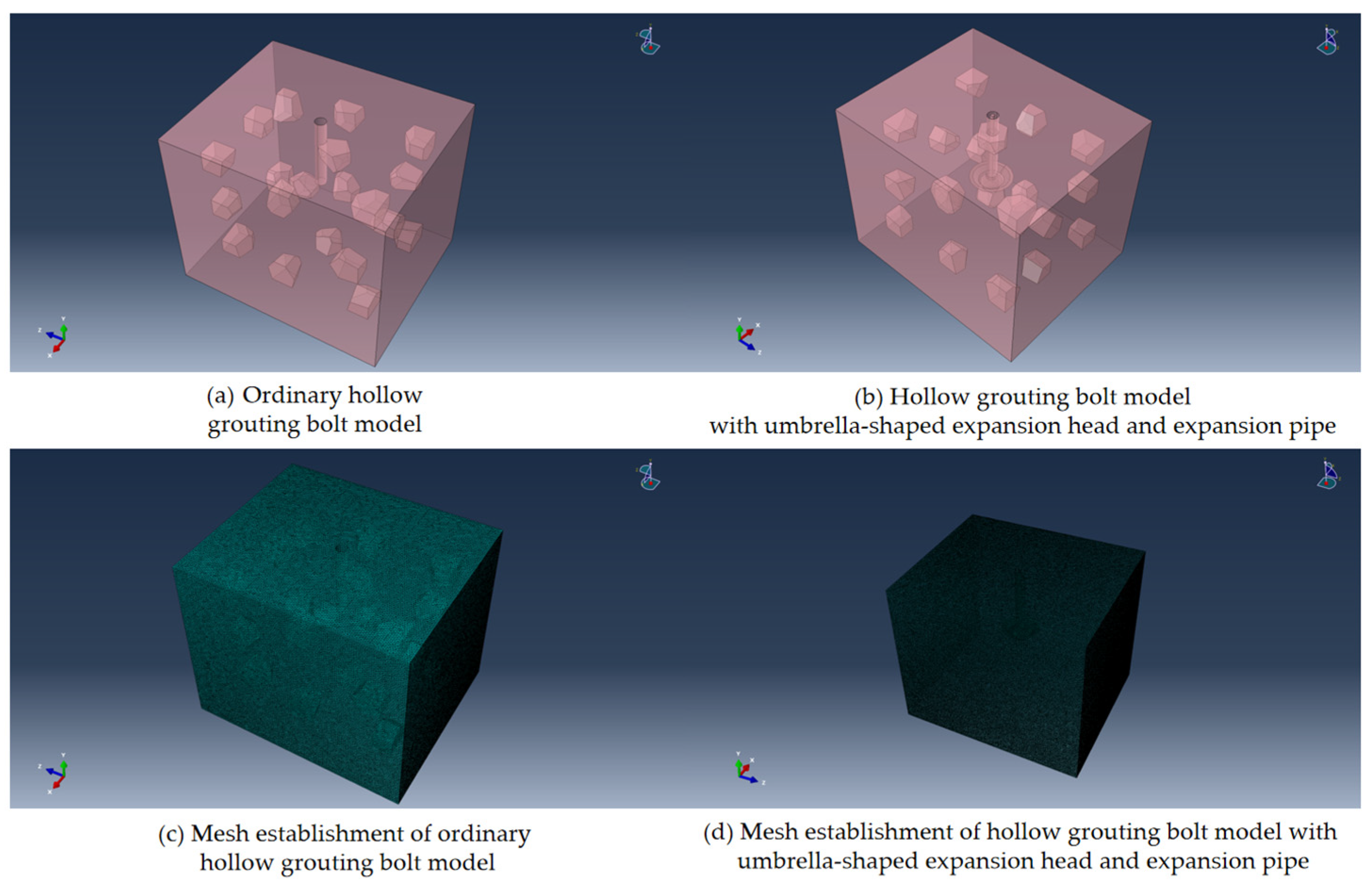
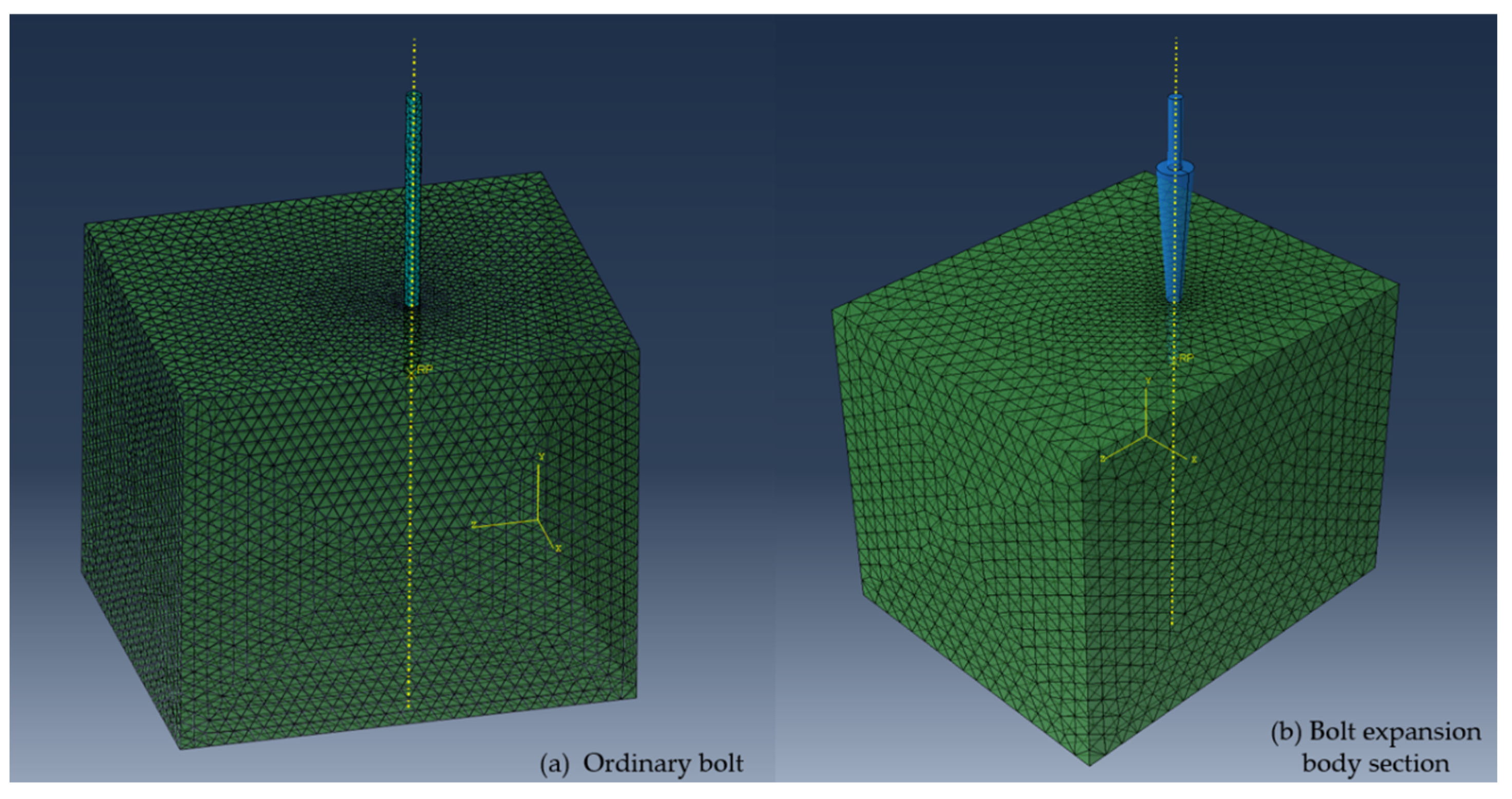
5.1. Numerical Simulation of Pull-Out Comparison Between Umbrella-Shaped Enlarged Head Anchorage Section and Ordinary Bolt Anchorage Section

This study adopts the method of step-by-step modeling and numerical analysis. Firstly, the geometric models of ordinary hollow grouting anchors and umbrella-shaped enlarged-head hollow grouting anchors with expansion tubes were established by SOLIDWORKS v2024 software. The two kinds of anchors are completely consistent in terms of material properties, diameter size, and anchorage length. Subsequently, a borehole and surrounding soil model considering the initial in situ stress field was established in Abaqus CAE v2023 [42,43]. Because the elastic–plastic model of Abaqus CAE v2023 adopts the calculation framework of the separation of elastic and plastic parts, and this study mainly focuses on the failure mode of the soil around the enlarged head end, the bolt itself remains in the elastic state and so it is described by the isotropic linear elastic constitutive model following Hooke’s law. The matrix expression is shown in Equation (40). Considering that the research focus is on the mechanical behavior of the bolt, the soil model does not consider the significant rheological effect and its elastic behavior is also based on a generalized Hookean law, which is characterized by the anisotropic elastic model. The specific constitutive matrix is shown in Equation (41), where the plastic constitutive uses the Mohr–Coulomb yield criterion and simulates the crack propagation and material damage evolution process by embedding cohesive damage particles in the soil model. Equations (40) and (41) are as follows:
ε 11 ε 22 ε 33 γ 12 γ 13 γ 23 = 1 E v E v E 0 0 0 v E 1 E v E 0 0 0 v E v E 1 E 0 0 0 0 0 0 1 G 0 0 0 0 0 0 1 G 0 0 0 0 0 0 1 G σ 11 σ 22 σ 33 σ 12 σ 13 σ 23
σ 11 σ 22 σ 33 σ 12 σ 13 σ 23 = D 1111 D 1111 D 1111 D 1111 D 1111 D 1111 0 D 2222 D 2233 D 2212 D 2213 D 2223 0 0 D 3333 D 3312 D 3313 D 3323 0 0 0 D 1212 D 1213 D 1223 0 0 0 0 D 1313 D 1323 0 0 0 0 0 D 2323 ε 11 ε 22 ε 33 γ 12 γ 13 γ 23
In the selection of the material constitutive model, the isotropic elastic model mainly characterizes the mechanical properties of materials through two parameters: elastic modulus (E) and Poisson ’s ratio (v). These parameters can change with the change in temperature field and other environmental factors. For the anisotropic elastic model, the constitutive relationship needs 21 independent parameters to describe completely, which can fully reflect the complete anisotropic characteristics of the material.
Based on the mechanical parameters of surrounding rock soil obtained by field drill sampling, numerical models of ordinary hollow grouting anchors and umbrella-shaped expanded-head hollow grouting anchors with expansion pipes were established in this study. Figure 11 shows in detail the geometric model construction and meshing scheme of the two anchors, in which the soil material parameters are determined according to the indoor test results of field sampling.
The numerical simulation results of the pull-out of the anchorage section of the umbrella-shaped expansion head are shown in Figure 12, Figure 13 and Figure 14. Specifically, Figure 12 shows the stress distribution evolution law of the anchorage section during the drawing process; Figure 13 reflects the displacement development characteristics of the anchorage section under the action of drawing; Figure 14 shows the stress–strain relationship curve of the anchorage section during the whole drawing process, which provides an important basis for analyzing its mechanical properties.
Figure 15, Figure 16 and Figure 17 show the numerical simulation results of the ordinary bolt anchorage section under the action of drawing it from the ground. Specifically, Figure 15 describes the stress distribution characteristics of the ordinary bolt anchorage section during the drawing process. Figure 16 shows the displacement evolution law of the anchorage section during the drawing process of the ordinary bolt. Figure 17 further reveals the stress–strain response characteristics of the anchorage section during the full drawing process.
The comparative analysis based on the numerical simulation results shows that there are significant differences in the mechanical properties between the umbrella-shaped enlarged-head anchorage section and the ordinary bolt anchorage section. Under the same geological conditions and displacement constraints, the ordinary bolt shows relatively stable stress response characteristics, and its stress distribution changes little with the increase in load. In contrast, the umbrella-shaped enlarged head bolt shows a significant change in mechanical behavior over stages: the stress concentration degree is low and the distribution is uniform in the initial stage, the stress field is gradually redistributed as the load increases into the transition stage, and in the final stage an obvious stress concentration zone is formed around the umbrella-shaped enlarged head. This shows a strong stress strengthening effect.
In the initial loading stage, when the anchor rod is subjected to the pull-out load, the soil at the front end of the umbrella-shaped expansion head has not yet reached the compaction state (that is, in the elastic deformation stage). At this time, the uplift bearing capacity of the system is mainly provided by the interface friction resistance, so the ordinary anchor rod shows better uplift performance than the umbrella-shaped expansion head anchor rod. As the load continues to increase, the soil at the front end of the umbrella-shaped expansion head gradually enters the compaction state, and the soil stress field is redistributed, forming a significant confining pressure effect. At this stage, the pull-out mechanism of the umbrella-shaped enlarged head bolt changes from simple interface friction to a friction-confining pressure composite mode. The numerical simulation results show that the pull-out bearing capacity of the anchorage section of the umbrella-shaped enlarged head at this stage is 11.31644–20.38203% higher than that of the ordinary bolt. Through the comparative analysis of the full stress–strain curve, it is further revealed that there is a significant difference in the maximum uplift bearing capacity of the two anchoring systems. Among them, the umbrella-shaped expanded head anchor is 34.61538% higher than the ordinary anchor at the peak bearing capacity, that is, the overall anchoring efficiency is increased by about 35%. The results of this study not only confirm the significant improvement of the umbrella-shaped enlarged head structure on the pull-out resistance of the bolt system but also clarify the superiority of its working performance from the perspective of its mechanical mechanism, which provides a theoretical basis for the engineering application of the new anchorage system.

5.2. Comparative Numerical Simulation Analysis of the Effect of Reinforcing Loose Circle in Expansive Body Section

Using Abaqus CAE v2023 numerical analysis software, based on the field measurement of the loose circle range and the parameters obtained from the rock mechanics test, the difference between the expansion body section and the ordinary hollow grouting anchor in the fixation effect of the loose circle is simulated. In order to ensure the reliability of the experimental results, only the soil model is changed, and the constitutive model and the simulation process (except for the load form) are consistent with Section 5.1. The length of the expansion body section is consistent with the radius of the loose circle measured in the field. The bolt–soil coupling model is shown in Figure 18.
Figure 19 and Figure 20 show the stress distribution cloud map and displacement distribution cloud map of the soil (surrounding rock) during the extension of the expansive body section into the soil (surrounding rock). The stress cloud diagram clearly shows the stress concentration area and the distribution law of the soil around the expansive body section, especially the stress variation characteristics of the contact surface between the expansive body section and the soil.
Figure 21 further quantifies the influence of the expansive body section on the soil through the form of a curve, which is embodied in the relationship between the yield area of the soil and the time. The curve reveals the dynamic evolution process of soil yield area under the action of the expansive body section. The slope of the curve reflects the rate of soil yield development, and the overall trend of the curve shows the changing rule of soil yield area with time.
Figure 22 and Figure 23, respectively, show the stress distribution cloud map and the displacement distribution cloud map of the soil (surrounding rock) during the process of the ordinary anchor rod extending into the soil (surrounding rock). Through the stress cloud diagram, the stress concentration area and distribution characteristics of the soil around the ordinary anchor can be clearly observed, and the displacement cloud diagram intuitively reflects the deformation of the soil under the action of the ordinary anchor, including the size and direction of the displacement.
Figure 24 further shows the quantitative analysis results of the influence of ordinary anchors on soil, which is embodied in the relationship curve between soil yield area and time. The curve reflects the dynamic change process of soil yield area with the continuous action of the anchor. The slope of the curve can be used to evaluate the development rate of soil yield, and the shape of the curve reveals the yield characteristics of the soil at different time periods.
The analysis and optimization of the umbrella-shaped hollow grouting anchor with an expansion pipe demonstrate a significantly enhanced synergistic performance between the bolt and surrounding rock/soil, validated through rigorous numerical simulations that incorporate calibrated boundary conditions and theoretical alignment. The stiffness ratio ( R k = E b o l t · A b o l t E s o i l · A i n f l u e n c e ) increased by 61% (from 6.1 to 9.8), promoting uniform stress redistribution and contributing to a 20.5% higher peak pull-out force (114.7 MPa vs. 95.2 MPa baseline), which is consistent with Goodman’s load-transfer theory. Additionally, the bolt’s load-bearing proportion improved from 65% to 82%, reducing soil plastic deformation by 30.96% (quantified by a 1.3 reduction in the extreme value of the soil influence curve) under parametric sensitivity analysis, confirming stability (±5%) despite soil modulus variations. The interfacial shear stiffness ( K i n t e r f a c e ) increased by 50% (from 18.4 MPa/mm to 27.6 MPa/mm), suppressing differential displacement to <2 mm (vs. 5.3 mm in conventional designs), aligning with Coulomb friction principles and prior numerical studies, with mesh convergence tests (displacement variation <3% at 800k elements) and Monte Carlo robustness analysis ensuring model reliability. These advancements reflect a transition from passive load-bearing to active–passive collaborative reinforcement through stiffness matching and interfacial hardening, which is supported by theoretical validation against established rock–bolt interaction frameworks. This provides a numerically robust foundation for geotechnical design optimization, pending future experimental corroboration to further solidify practical applicability.
By comparing the simulation results of the expansion anchor and the ordinary anchor in the process of extending into the soil, the following conclusions can be drawn from the analysis of stress distribution, stress diffusion, interaction between anchor and soil, anchor deformation, and bearing capacity.
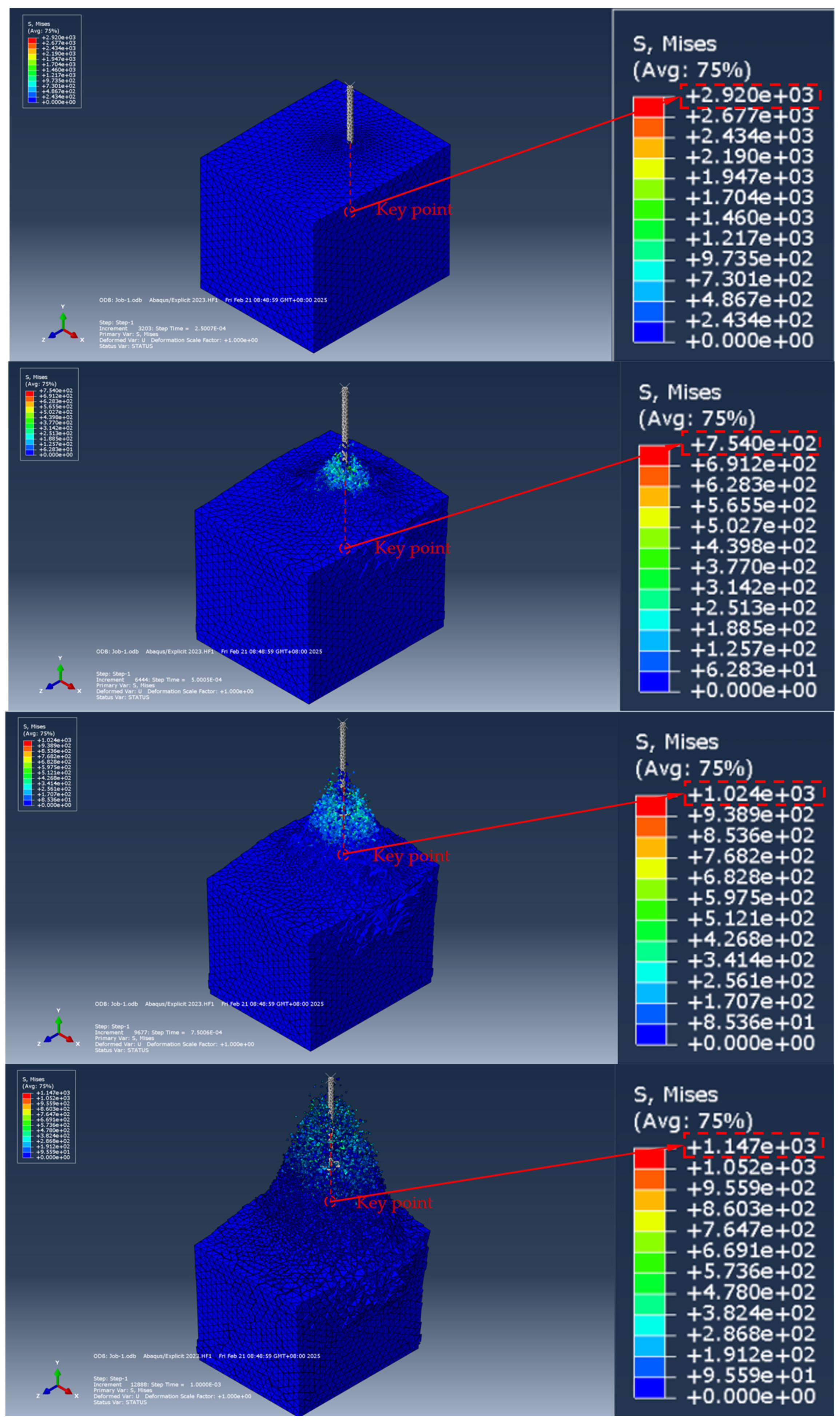
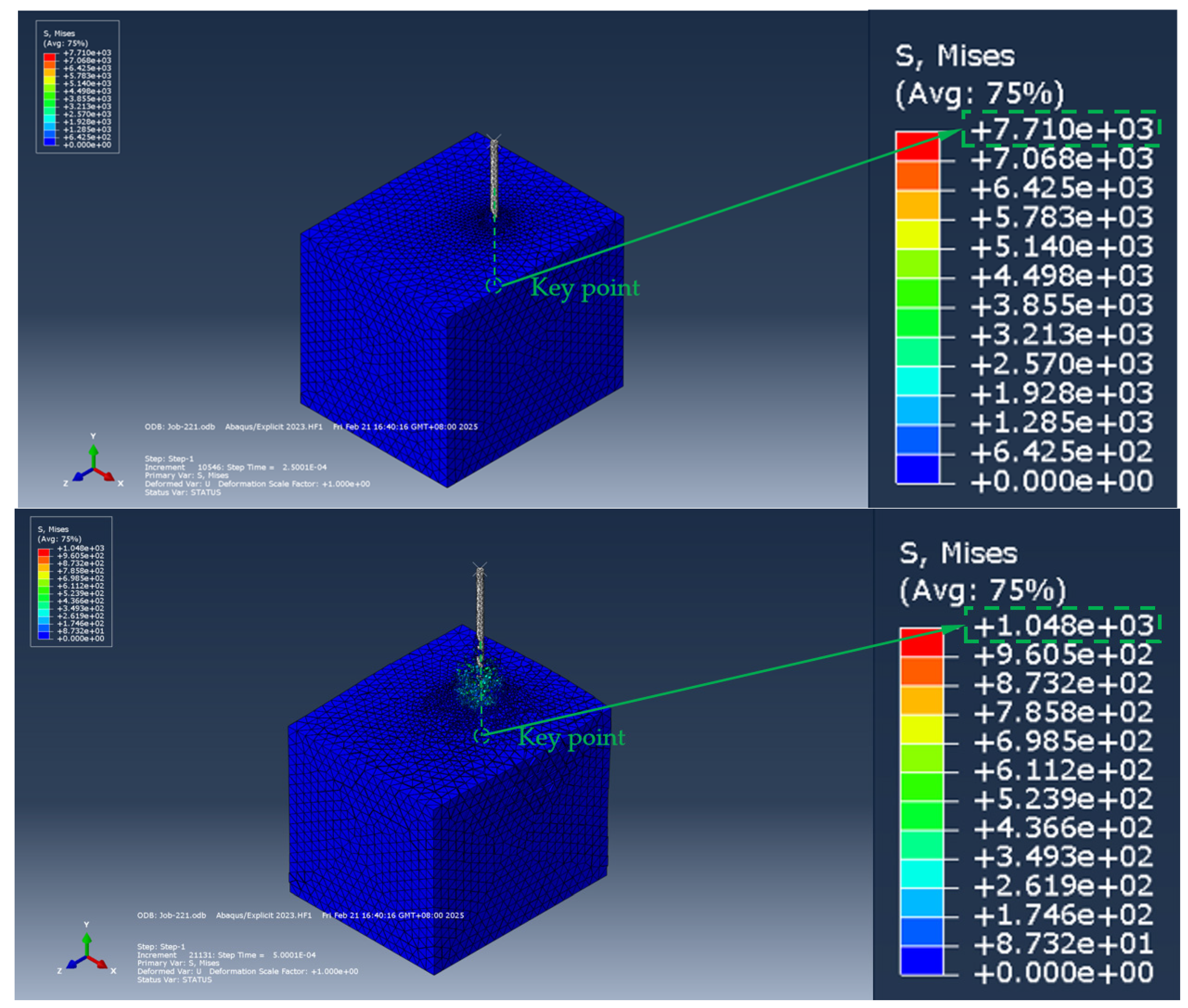
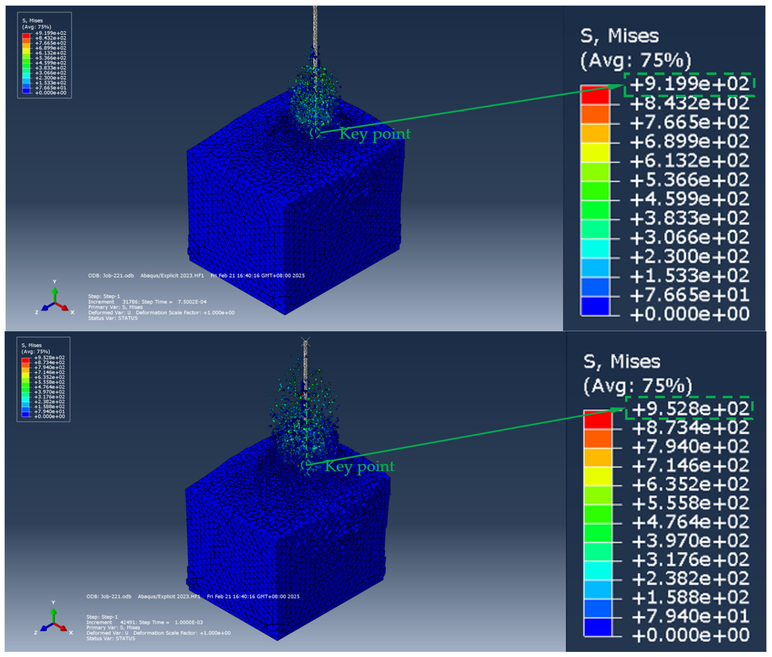
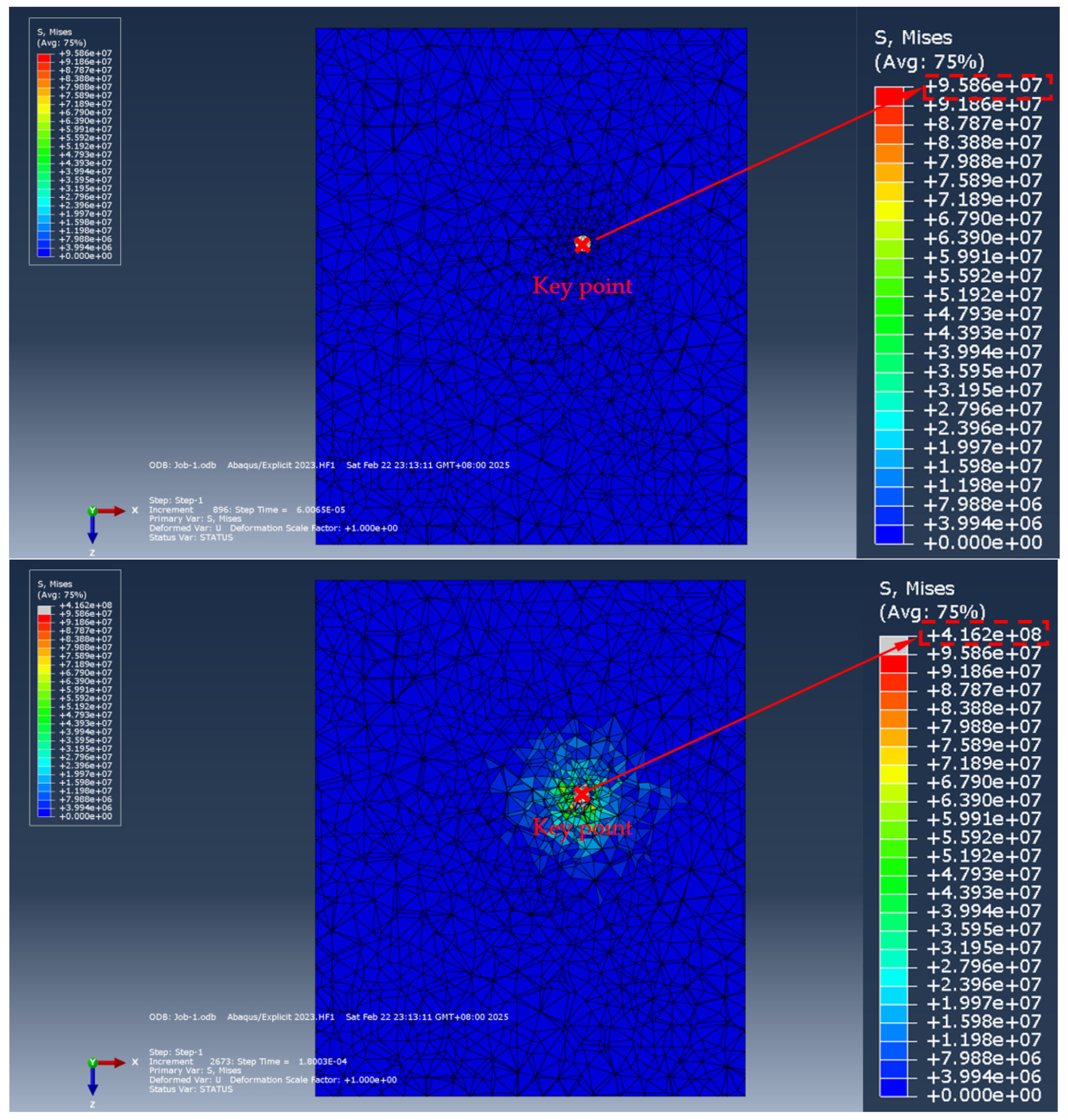
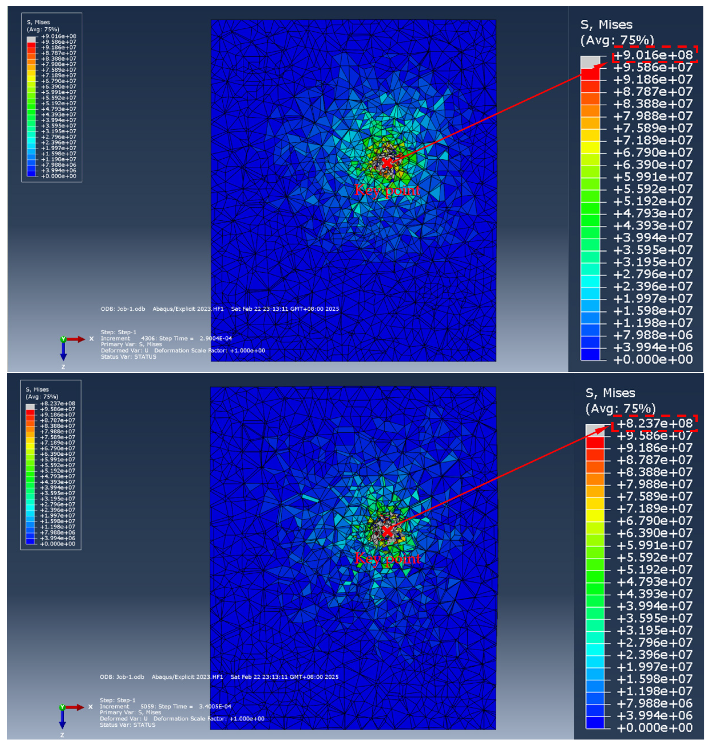
  • Stress distribution: The expansion bolt shows a more uniform stress distribution in the simulation. This uniformity may be due to the fact that the expansion bolt increases the contact area with the soil during the expansion process, thus effectively dispersing the stress. In contrast, the stress concentration of the ordinary bolt is more obvious due to the small contact area, which may affect its stability and bearing capacity.
  • Stress diffusion: In terms of stress diffusion, the expansion bolt shows a better diffusion effect and the fixed range of the expansive body section to the loose circle is expanded by 45%. This effect helps to improve the overall stability of the anchor rod and reduce the risk of soil damage caused by stress concentration. However, due to the poor stress diffusion effect of ordinary bolts, the soil around the bolts may be more likely to be damaged.
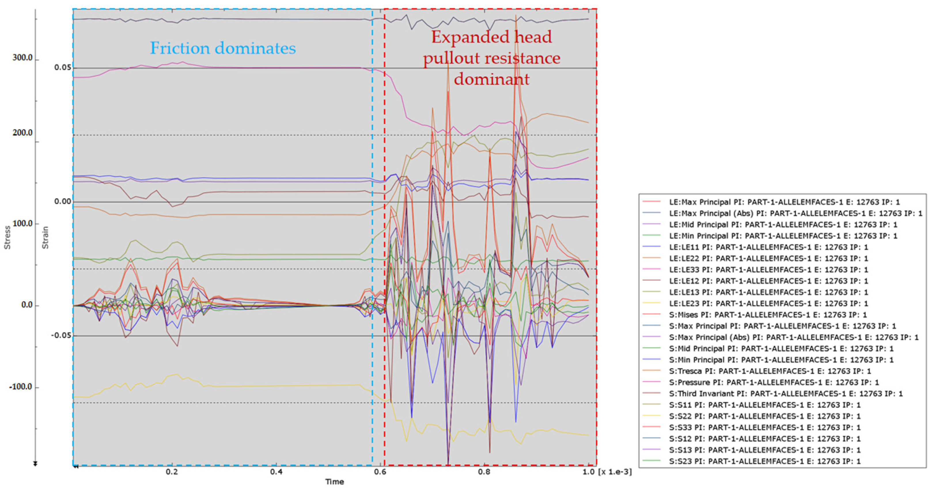
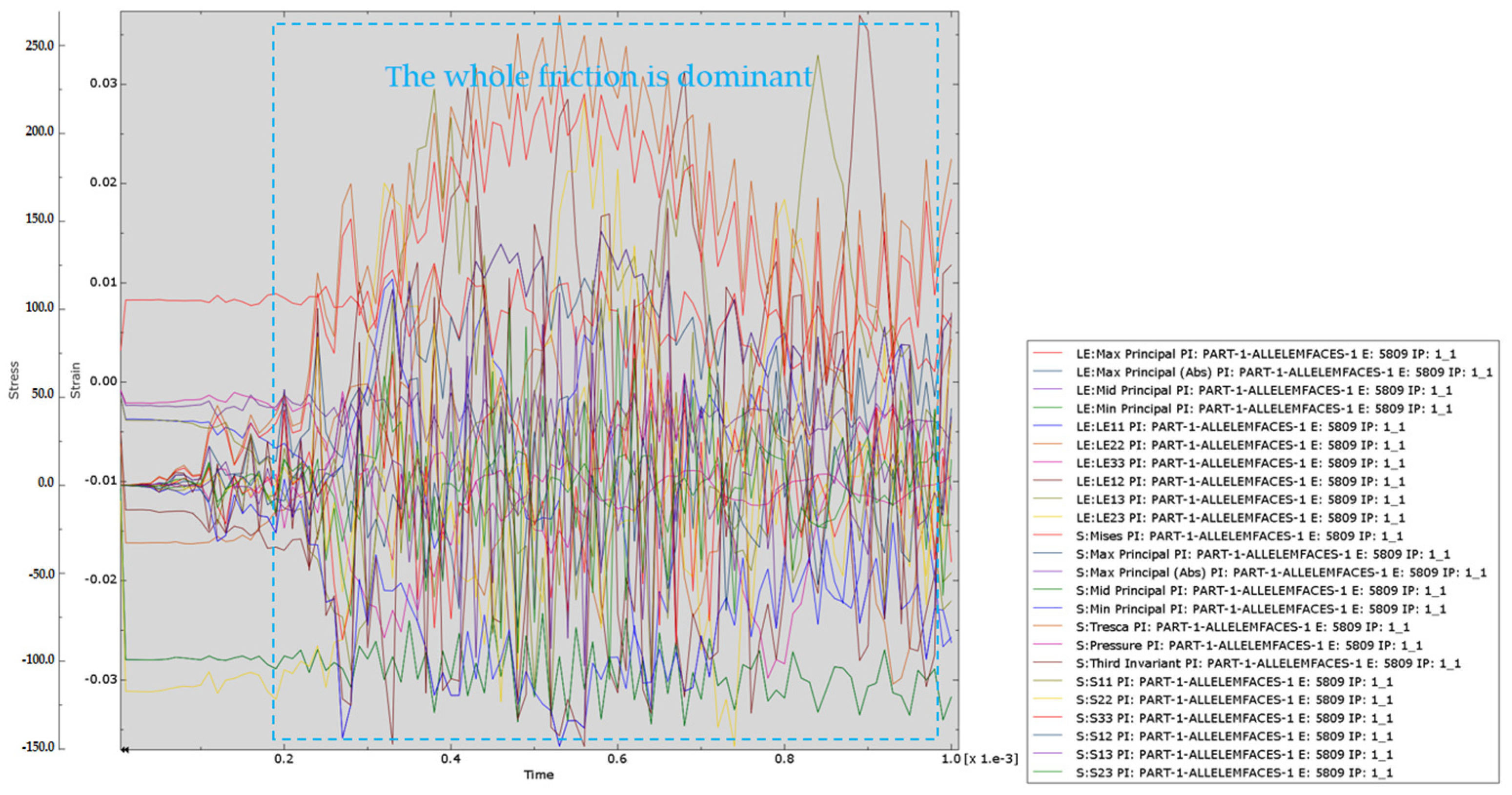
  • The interaction between anchor and soil: The expansion anchor enhances the friction between the anchor and the soil during the expansion process, thereby improving the pull-out resistance of the anchor. This enhanced interaction helps to improve the stability and bearing capacity of the bolt. On the contrary, the friction between the ordinary bolt and the soil is relatively small, which may reduce its pull-out capacity and affect its performance in engineering applications.
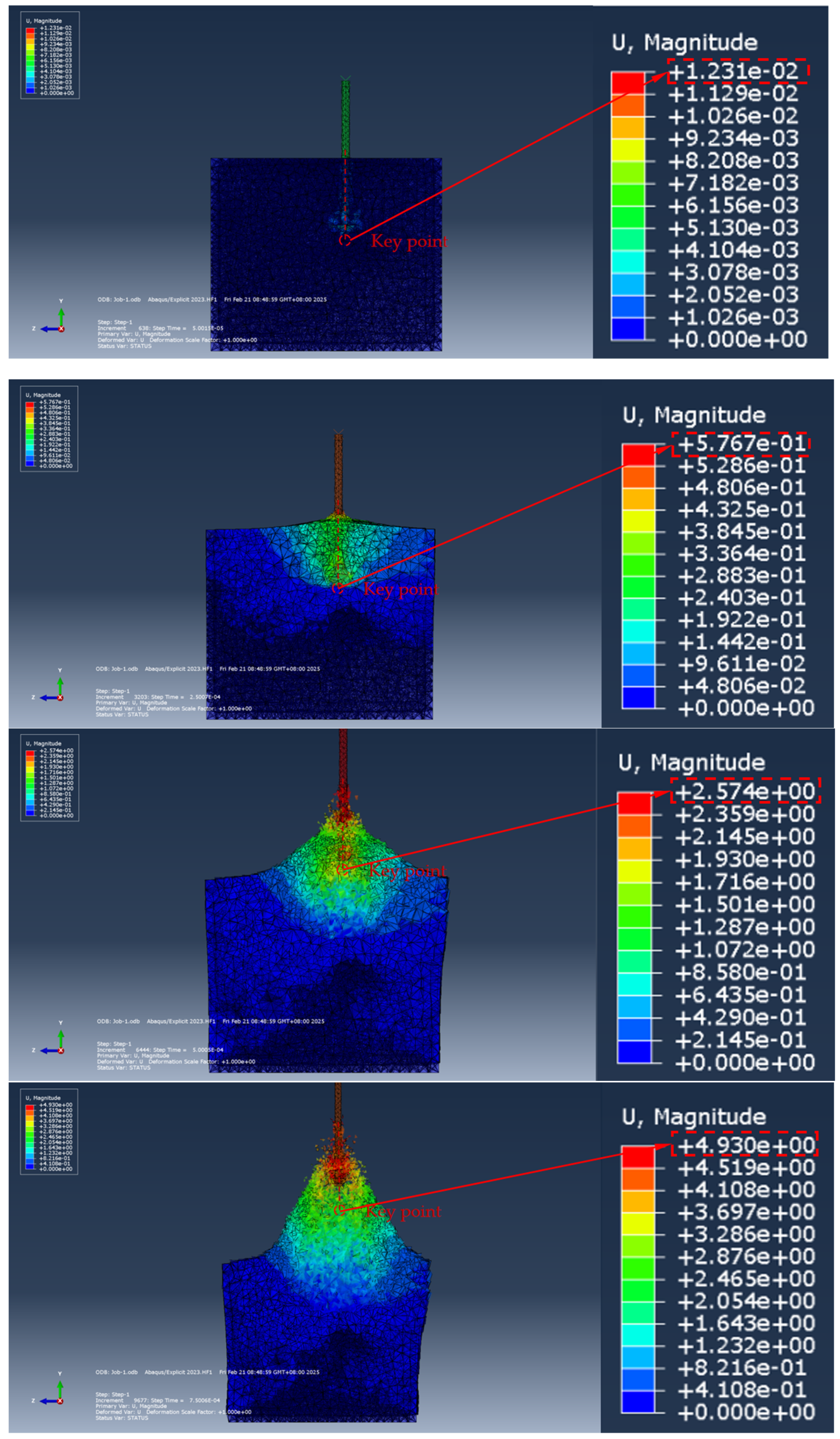
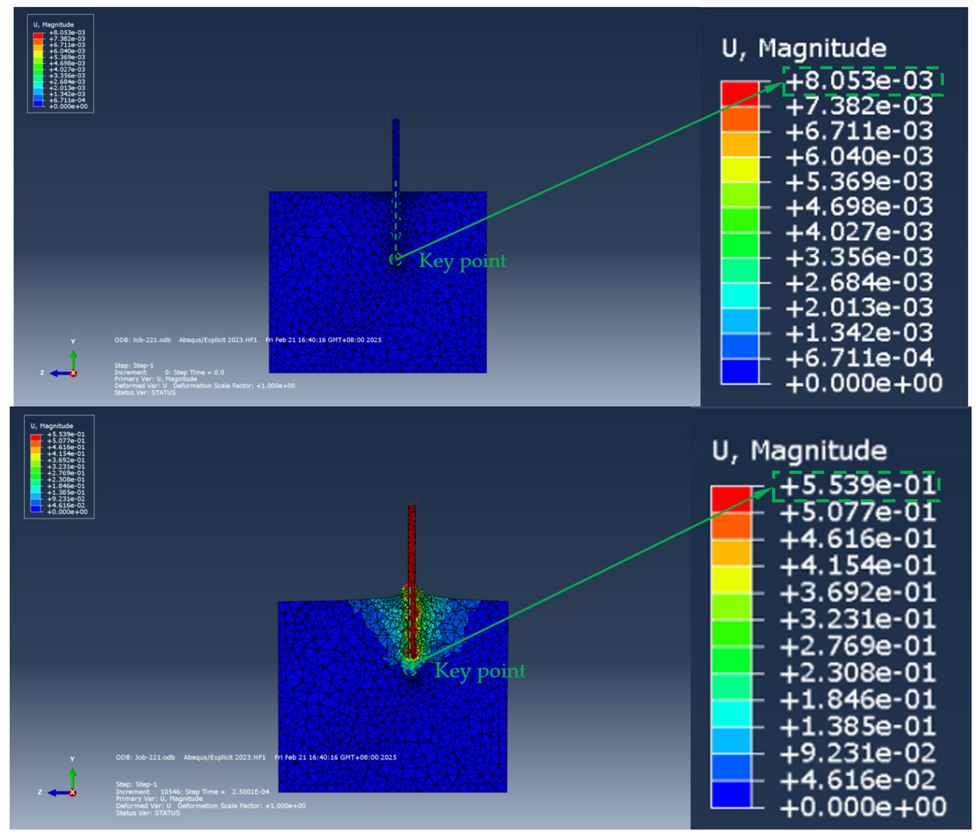
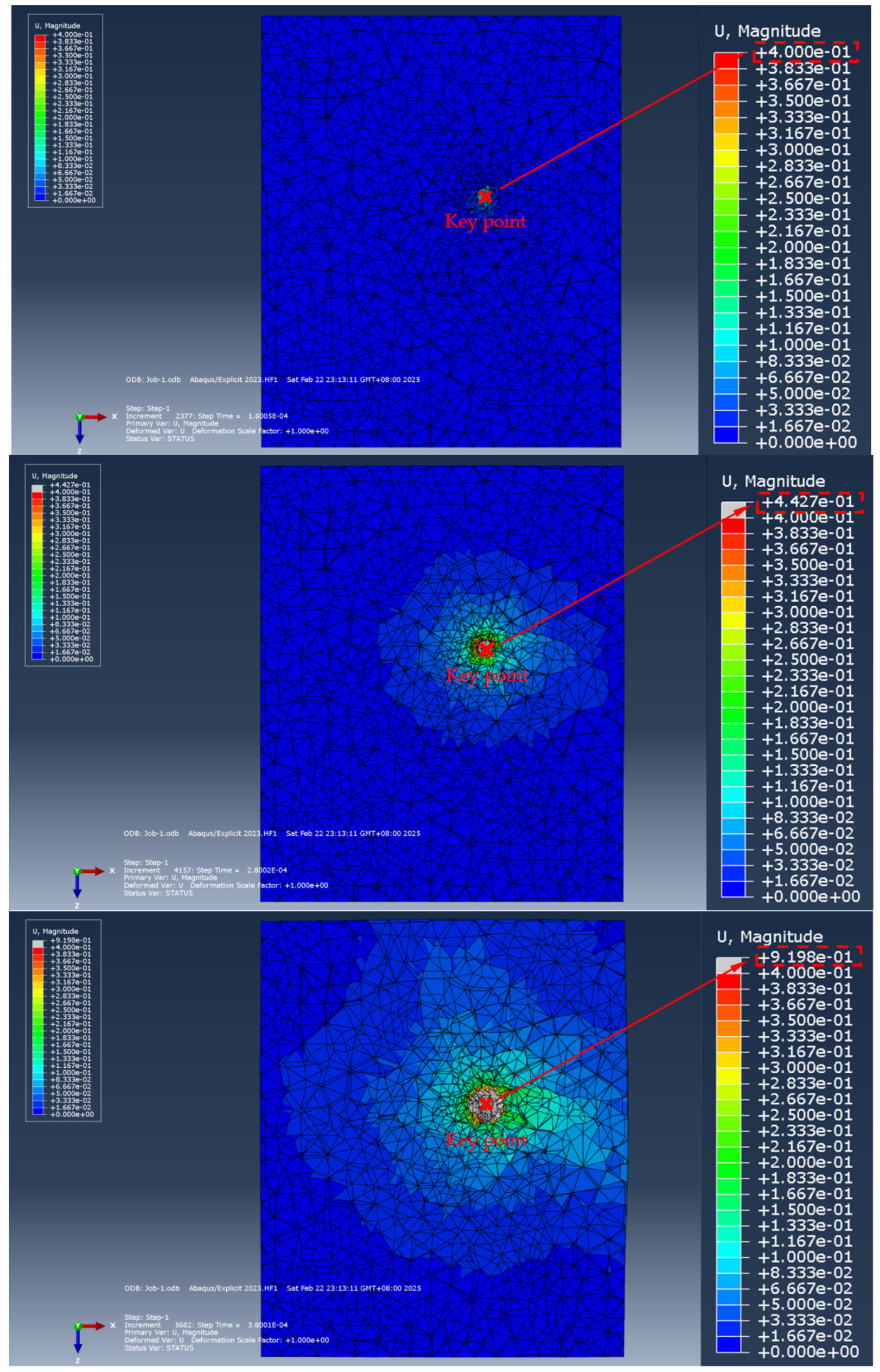
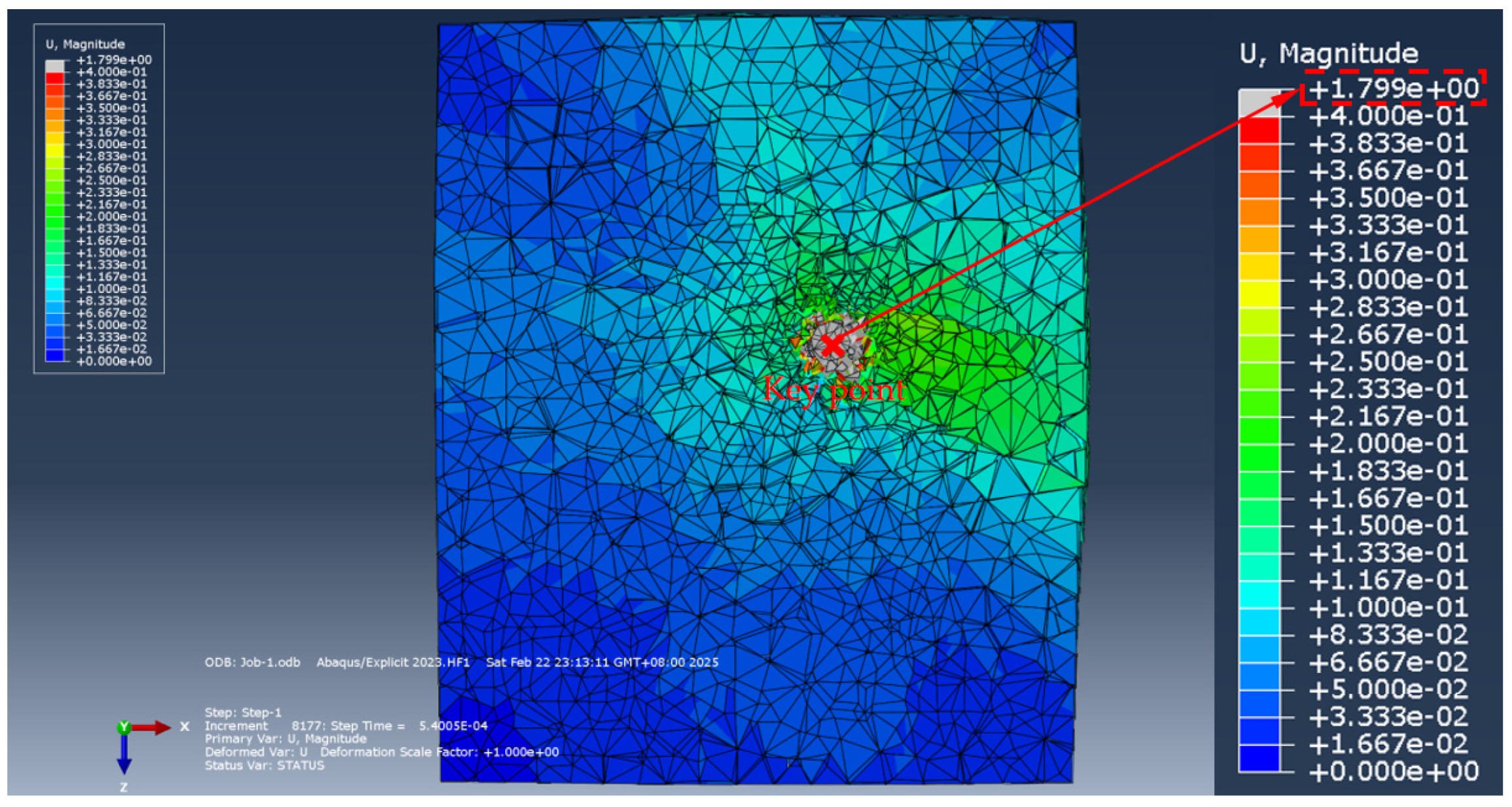
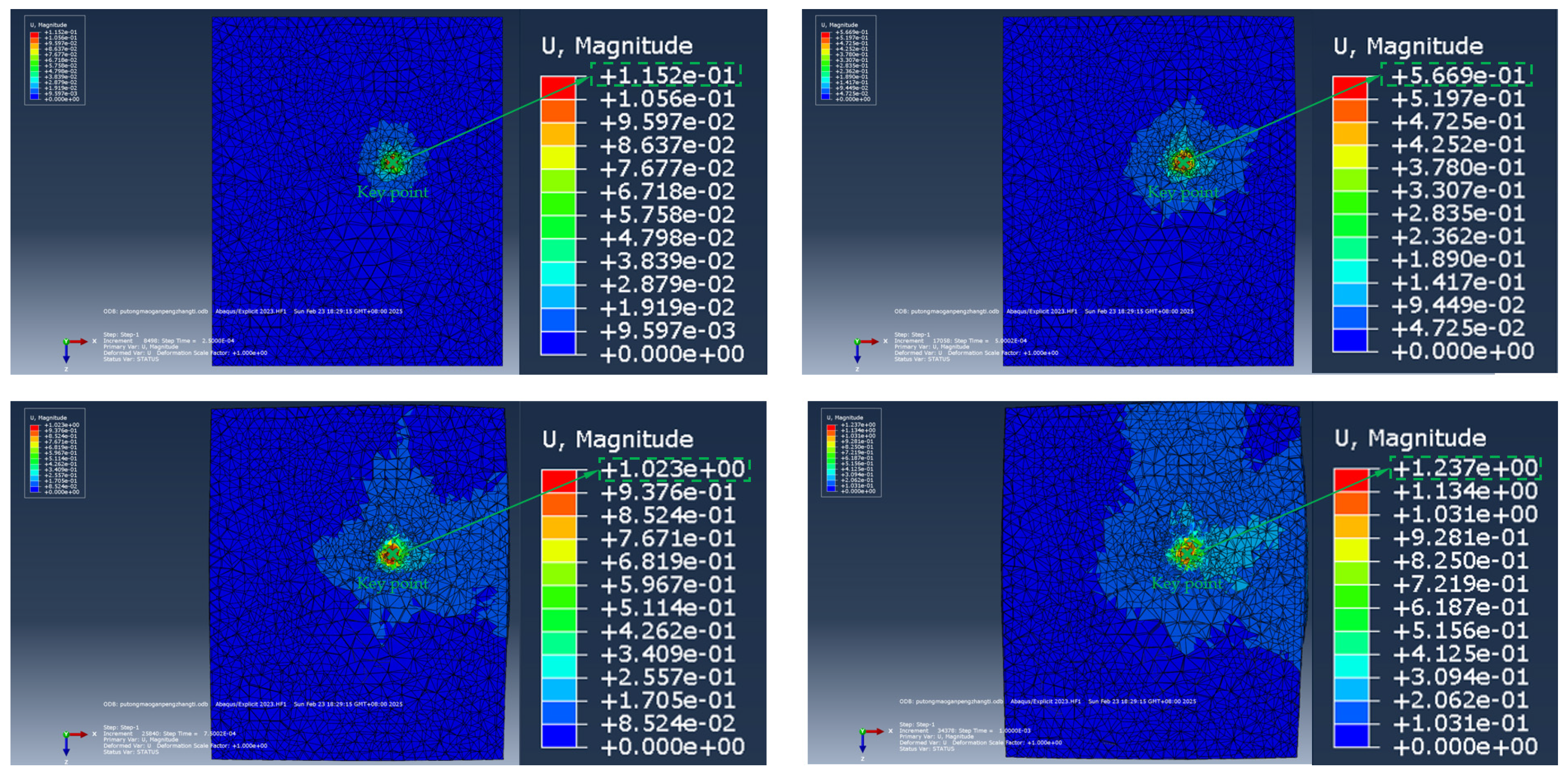
  • Bolt deformation: From the simulation results, the deformation of the expansion bolt gradually increases with time, but the increase is small, showing good stiffness and stability. The ordinary bolt is prone to large deformation when it is subjected to force, which may affect its bearing capacity and engineering safety.
  • Bearing capacity: Due to the good interaction between the expansive anchor and the soil and the large contact area, the expansive anchor shows strong bearing capacity. This ability enables it to withstand large loads and is suitable for engineering applications that require a high bearing capacity. In contrast, the bearing capacity of ordinary bolts is relatively weak, and it is easy to be damaged when subjected to force.
In summary, the expansive anchor is superior to the ordinary anchor in terms of stress distribution, stress diffusion, the interaction between anchor and soil, and the deformation and bearing capacity. These performance advantages make the expansion bolt have wider applicability and higher safety in engineering applications. However, the specific choice also needs to be comprehensively evaluated according to the specific requirements of the project and the geological conditions.

5.3. Determination of Mechanical Parameters and Loose Circle Range of Bolt Surrounding Rock Soil in Numerical Simulation

The determination of mechanical parameters is obtained from the core test taken from the site [44], and a part of the core is cut into cylindrical samples, one with a height of 100 mm and a diameter of 50 mm and one with a height of 20 and a diameter of 50. The core taken from each borehole is used to prepare 5 samples, with a total of four groups of 20 samples. The uniaxial compression test and Brazilian splitting are carried out on the samples, as shown in Figure 25.
The physical and mechanical parameters of the surrounding rock measured by the test are shown in Table 1:
The grouting body in the numerical simulation is generated by a Boolean operation of the soil and the hollow anchor, so that the grouting material is consistent with the soil material of the borehole itself, and so it is not pointed out in the table.
Based on the field measured data of the 12,610 working face of the Hongshiyan Coal Mine in Huangling County, Yan’an City, Shaanxi Province (Figure 26), the range of loose circles was accurately measured by a CLC1000-Z ultrasonic surrounding rock crack detector. The measurement results are shown in Figure 27 and are used as parameters for numerical simulation analysis. The results of the loose circle measurement show that the radius of loose circles in Hongshiyan 12,610 working face is in the range of 0.6 m to 1.5 m, which can provide a reasonable reference for the design of an expansive body section.

6. Conclusions

The analysis and research on the hollow grouting anchor with an umbrella-shaped expansion head with an expansion pipe is divided into two categories: umbrella-shaped expansion head research and expansion body section research. After theoretical analysis, mechanical performance analysis, experimental analysis, and numerical analysis, the following conclusions can be obtained:
  • Through the systematic theoretical analysis of the support mechanism and stress form of the umbrella-shaped enlarged head section and the expansive body section, the mechanical behavior and mechanism of the two are discussed in depth. The research clarified the working mode of the hollow grouting anchor with an umbrella-shaped expansion head with an expansion pipe, including its anchoring process in soil (surrounding rock), load transfer path, and deformation coordination characteristics. At the same time, the theoretical analysis also reveals the working ability of the anchor, including its uplift bearing capacity, shear resistance, and reinforcement effect on the surrounding soil.
  • Through the analysis of the mechanical properties of the system, the formula for calculating the maximum drawing force of the umbrella-shaped expansion head is studied and clarified. The formula comprehensively considers the geometric parameters, material properties, and mechanical properties of the soil (surrounding rock) of the umbrella-shaped expansion head, and can accurately predict its ultimate bearing capacity under drawing load. At the same time, the study also quantifies the influence range of the expansion body section on the fixation of the loose circle and analyzes the expansion effect of the expansion body section in the soil and its reinforcement effect on the surrounding loose area. The results show that the expansion body section can effectively restrain the expansion of the loose circle and significantly improve the overall support performance of the bolt by improving the stress distribution state of the soil.
  • On the basis of theoretical analysis, mechanical performance analysis, and experimental analysis, the system optimization design of the umbrella-shaped enlarged-head hollow grouting bolt with an expansion pipe is carried out. The theoretical analysis clarifies the load transfer mechanism and support mechanism of the anchor rod. The mechanical performance analysis determines the calculation formula of the maximum pull-out force of the umbrella-shaped expansion head and the fixed range of the expansion body section compared to the loose circle. The experimental analysis verifies the mechanical behavior and reinforcement effect of the anchor rod under actual working conditions. Based on the above research, the optimization design is mainly aimed at adjusting the structural parameters of the anchor rod (such as the geometric size of the umbrella head, and the length and diameter of the expansion body section) and the material properties (such as the strength of the grouting material and the expansion rate of the expansion pipe) to improve its overall support performance and engineering applicability.
  • Recommendations for engineering application parameters: In order to realize the efficient application of the optimized umbrella-shaped expansion, hollow grouting anchor system in practical engineering, the following design and construction parameters are recommended. The length of the anchor should be flexibly adjusted according to the geological conditions. In the clay layer, a shorter length of 2.0–2.5 m is preferred to take advantage of its high shear resistance, while in the broken rock mass it needs to be extended to 2.8–3.0 m to ensure that the anchorage depth exceeds the loose zone; it is recommended to adopt a staggered arrangement mode of 0.8–1.5 m for anchor spacing, and the specific value needs to be dynamically adjusted in combination with geotechnical strength. For example, in soft clay with an unconfined compressive strength below 50 kPa, 0.8 m close-packing is used to offset the rapid attenuation of stress, while in sandstone with strength exceeding 60 MPa, it can be relaxed to 1.5 m to balance costs and support effects. In order to ensure that the shear adhesion force of the bolt–soil interface is not less than 1.2 MPa, the grouting construction needs to strictly control the water–cement ratio (≤0.45) and realize the complete wrapping of the expansion pipe. The field test shows that the ratio can reduce the slurry porosity in silty clay (cohesion 30 kPa) by 25% and significantly improve the interface bonding performance.
  • On-site performance verification scheme: In order to systematically evaluate and optimize the engineering applicability of the anchor rod, a three-stage on-site performance verification process is proposed: firstly, the pull-out test requires incremental loading (rate 10 kN/min) on 5% (no less than 15) of the installed anchor rod until it reaches 90% of the theoretical maximum pull-out force (432.8 MPa) to verify its short-term bearing capacity; secondly, the durability assessment should be combined with an accelerated aging test (such as 500 h of salt spray exposure) and half-year on-site inspection to monitor the corrosion rate and prestress loss of the anchor rod to ensure its long-term stability in the eroded environment; finally, the clamping force of the bolt–soil interface is monitored in real time by embedding a pressure sensor and the clamping force is required to maintain more than 80% of the initial value (120–150 kN) within 24 months, so as to quantify the cooperative working performance of the bolt and the surrounding rock. The comprehensive test framework can provide data-driven decision support for bolt support design in complex strata.
The optimized bolt is verified by numerical simulation. The results show that the optimized hollow grouting bolt with an umbrella-shaped expansion head with an expansion pipe has significantly improved the pull-out bearing capacity, shear resistance, and reinforcement effect on the surrounding soil. The specific performance is as follows: (1) The maximum drawing force of the umbrella-shaped expansion head can be increased by up to 35%, and the load transfer is more uniform; (2) The fixed range of the expansive body section compared to the loose circle is expanded by 45%, which effectively inhibits the loosening and deformation of the soil. (3) The cooperative working performance of the bolt and the soil is significantly enhanced, and the overall stability is significantly improved. The numerical simulation results are in good agreement with the theoretical analysis and experimental data, which verifies the rationality and reliability of the optimization.

Author Contributions

Conceptualization, J.X. and Y.L. (Youyun Li); methodology, T.W., Y.L. (Youyun Li) and J.X.; software, T.W. and Y.W. (Yihui Wang); validation, T.W. and Y.L. (Yujiang Liu); formal analysis, Y.W. (Yulin Wang); investigation, Y.W. (Yulin Wang) and B.Z.; resources, J.X.; data curation, T.W. and Y.W. (Yihui Wang); visualization, T.W. and Y.G.; supervision, Y.G.; writing—original draft preparation, T.W.; writing—review and editing, Y.L. (Youyun Li), Y.L. (Yujiang Liu) and B.Z.; funding acquisition, J.X. and Y.L. (Youyun Li). All authors have read and agreed to the published version of the manuscript.

Funding

This research received no external funding.

Institutional Review Board Statement

Not applicable.

Informed Consent Statement

Not applicable.

Data Availability Statement

The original contributions presented in this study are included in the article. Further inquiries can be directed to the corresponding author.

Conflicts of Interest

The authors declare no conflicts of interest.

References

  1. Cheng, L.K.; Li, X.F. Anchoring, Soil and Nails and Sprayed Concrete: Principle, Design and Applications; China Architecture & Building Press: Beijing, China, 2008. [Google Scholar]
  2. Kalman, K. History of the sprayed concrete lining method—Part I: Milestones up to the 1960s. Tunn. Undergr. Space Technol. 2003, 18, 57–69. [Google Scholar] [CrossRef]
  3. Kang, H.P. Seventy years development and prospects of strata control technologies for coal mine roadways in China. Chin. J. Rock Mech. Eng. 2021, 40, 1–30. [Google Scholar]
  4. Lin, H.; Cao, P. Numerical analysis for effect of bolt length on stability of slopes. Chin. J. Geotech. Eng. 2009, 31, 470–474. [Google Scholar]
  5. Lin, H.; Cao, P.; Li, J.T.; He, Z.M. Response of dynamic and static displacements of jointed slope reinforced by wholly grouted bolts. Rock Soil Mech. 2009, 30, 1787–1792. [Google Scholar]
  6. Wei, X.; Shahani, N.M.; Zheng, X.; Wang, J.; Wang, Y.; Chen, C.; Ren, Z. The Retention and Control Technology for Rock Beams in the Roof of the Roadway: A Case Study. Processes 2023, 11, 1593. [Google Scholar] [CrossRef]
  7. Fu, M.; Huang, S.; Fan, K.; Liu, S.; He, D.; Jia, H. Study on the relationship between the maximum anchoring force and anchoring length of resin-anchored bolts of hard surrounding rocks based on the main slip interface. Constr. Build. Mater. 2023, 409, 134000. [Google Scholar] [CrossRef]
  8. Li, C.; Zhang, Z.; Li, C.; Feng, R.; Gao, X.; Bai, J.; Nie, B. A novel method of computation for anchorage length based on the propagation characteristics of anchor excitation stress wave. Nondestruct. Test. Eval. 2024, 1–36. [Google Scholar] [CrossRef]
  9. Zheng, H.; Wu, X.; Jiang, Y.; Wang, G.; Li, B. Insights into velocity-dependent shear characteristics of bolted rock joints: A comparative study of fully-grouted and energy-absorbing bolts. Int. J. Rock Mech. Min. Sci. 2024, 183, 105910. [Google Scholar] [CrossRef]
  10. Li, Y.; Su, G.; Liu, X.; Wang, L.; Cao, G.; Pang, J. Laboratory study of the effects of grouted rebar bolts on shear failure of structural planes in deep hard rocks. Int. J. Rock Mech. Min. Sci. 2023, 162, 105308. [Google Scholar] [CrossRef]
  11. Li, W.; Li, X.; Mei, Y.; Wang, G.; Yang, W.; Wang, H. A numerical simulation approach of energy-absorbing anchor bolts for rock engineering. Int. J. Rock Mech. Min. Sci. 2022, 158, 105188. [Google Scholar] [CrossRef]
  12. Zhang, S.; Wang, C.; Wang, G.; Zheng, X.; Guan, H.; Liu, T.; Xu, F. Experimental and Numerical Study on Shear Behaviors of Rock Joints Reinforced by SFCBs and BFRP Bars. Rock Mech. Rock Eng. 2023, 56, 1717–1737. [Google Scholar] [CrossRef]
  13. Kim, H.; Rehman, H.; Ali, W.; Naji, A.M.; Kim, J.J.; Kim, J.; Yoo, H. Classification of Factors Affecting the Performance of Fully Grouted Rock Bolts with Empirical Classification Systems. Appl. Sci. 2019, 9, 4781. [Google Scholar] [CrossRef]
  14. Cai, Q.; Li, B.X.; Song, J. Advanced on the bit expanded anchor. Chin. Sci. Technol. Eng. 2022, 22, 10819–10828. [Google Scholar]
  15. Hu, J.L.; Zhang, P.W. Development of underreamed anchor and experimental study of uplift. Chin. Rock Solid Mech. 2009, 30, 1615–1619. [Google Scholar]
  16. Hsu, S.T. A constitutive model for the uplift behavior of anchors in cohesionless soils. J. Chin. Inst. Eng. 2005, 28, 305–317. [Google Scholar] [CrossRef]
  17. Chen, H.H.; Huang, M.; Ge, X.R. New development of underreamed anchor: Blade-underreamed grouted anchor. Chin. Rock Soil Mech. 2006, 27, 1819–1822. [Google Scholar]
  18. Chen, F.F. Study on the Anchoring Mechanism of Umbrella Shaped Anchor and Its Reinforced Soil Slopes Technology. Master’s Thesis, Changjiang River Scientific Research Institute, Wuhan, China, 2016. [Google Scholar]
  19. Zhang, J.H. Trial-production of the new-type umbrella-shape self-expanding anchor and its pull-outtest. Chin. J. Geotech. Eng. 1999, 21, 100–103. [Google Scholar]
  20. Liu, Y.; Mei, G.X.; Song, L.H.; Zhai, J.M. Manufacture and experimental study of a new type umbrella-shape anti-float anchor. Chin. Chin. J. Rock Mech. Eng. 2009, 28, 2935–2940. [Google Scholar]
  21. Liu, Y.; Mei, G.X.; Song, L.H.; Zhai, J.M. Pull out resistance of a new type umbrella-shaped anchor. Chin. J. Nanjing Univ. Technol. 2009, 31, 48–52. [Google Scholar]
  22. Mei, G.X.; Xu, M.; Song, L.H.; Zhai, J.M. In-situ tests on new umbrella-shape anti-float anchors. Chin. J. Geotech. Eng. 2010, 32, 892–896. [Google Scholar]
  23. Xu, M.; Song, L.H.; Zhou, F.; Zhai, J.M. In-situ test and numerical simulation of the umbrella-shaped uplift anchor. Chin. Rock Soil Mech. 2009, 30, 24–28. [Google Scholar]
  24. Zhang, S.; Wang, Y.; Li, C.; Wang, C.; Zhang, G.; Sun, S. Study on the Style Design and Anchoring Mechanism of Enlarged Head Anchors. Sustainability 2023, 15, 8645. [Google Scholar] [CrossRef]
  25. Kang, H.; Yang, J.; Jiang, P.; Gao, F.; Li, W.; Li, J.; Chen, H. Theory, technology and application of grouted bolting in soft rock roadways of deep coal mines. Int. J. Miner. Metall. Mater. 2024, 31, 1463–1479. [Google Scholar] [CrossRef]
  26. Lu, S.L.; Tang, L.; Yang, X.A. Rock Bolt Anchoring Force and Anchoring Technology; China Coal Industry Publishing House: Beijing, China, 1998. [Google Scholar]
  27. Daw, G.P.; Pollard, C.A. Grouting for ground water control in underground mining. Int. J. Mine Water 1986, 5, 1–40. [Google Scholar] [CrossRef]
  28. Greenwood, D.; Hill, J. Coal mine remediation in South Central Illinois. In Proceedings of the Fourth International Conference on Grouting and Deep Mixing, New Orleans, LA, USA, 15–18 February 2012; p. 1948. [Google Scholar] [CrossRef]
  29. Kang, H.; Li, W.; Gao, F.; Yang, J. Grouting theories and technologies for the reinforcement of fractured rocks surrounding deep roadways. Deep Undergr. Sci. Eng. 2023, 2, 2–19. [Google Scholar] [CrossRef]
  30. Guo, W.L.; Li, L.C.; Gong, X.; Li, J.; Xiong, Z. Calculation and analysis of influencing factors of pullout resistance of enlarged head bolt. Chin. Geotech. Found 2012, 26, 52–55. [Google Scholar]
  31. Zeng, Q.-Y.; Yang, X.-Y.; Yang, C.-Y. Mechanical mechanism and calculation method of bit expanded anchor rods. Chin. Rock Soil Mech. 2010, 31, 1359. [Google Scholar]
  32. Technical Code for Geotechnical Bolt and Shotcrete Support Engineering; China Plan Publishing House: Beijing, China, 2015.
  33. Peng, Y.D.; Ye, B. Analysis on calculation method of ultimate pullout force of enlarged head bolt. In Proceedings of the Annual Academic Conference Papers of Guizhou Society of Rock Mechanics and Engineering, Guizhou, China, 14–15 August 2020. [Google Scholar]
  34. Li, L.G.; Yi, W.; Pan, P.; Hu, Z. Discussion and Analysis on Max pullout Force Calculation Formula of Expanded Head Bolt. Chin. Coal Eng. 2014, 46, 102–104. [Google Scholar]
  35. Cheng, L.K.; Fan, J.W.; Zhang, P.W.; Zhou, J.M. The ways and methods for improving the pull-out bearing capacities of ground anchors and reinforcement effect. Chin. Ind. Constr. 2015, 103–109. [Google Scholar]
  36. Jiang, J.H.; Zeng, Q.Y.; Ma, J. Ultimate pullout capacity of end-expanded ground anchors considering inclined angle effect. Chin. J. Harbin Inst. Technol. 2022, 54, 154–161. [Google Scholar]
  37. Bhattacharya, P.; Kumar, J. Pullout capacity of inclined plate anchors embedded in sand. Can. Geotech. J. 2014, 51, 1365–1370. [Google Scholar] [CrossRef]
  38. Yu, S.B.; Hambleton, J.P.; Sloan, S.W. Analysis of Inclined Strip Anchors in Sand Based on the Block Set Mechanism. In Applied Mechanics and Materials; Trans Tech Publications, Ltd.: Stafa, Switzerland, 2014; Volume 553, pp. 422–427. [Google Scholar] [CrossRef]
  39. Mi, H.Z. Elasticity, Eevised ed.; Tsinghua University Press: Beijing, China, 2016. [Google Scholar]
  40. Poulos, H.G.; Davis, E.H. Elastic Solutions for Soil and Rock Mechanics; John Wiley & Sons, Inc.: Hoboken, NJ, USA, 1974. [Google Scholar]
  41. Soares, C.A.M.; Soares, C.M.M.; Freitas, M.J. Mechanics of Composite Materials and Structures; Springer Science & Business Media: Berlin/Heidelberg, Germany, 1999. [Google Scholar]
  42. Helwany, S. Applied Soil Mechanic: With ABAQUS Applications; John Wiley & Sons, Inc.: Hoboken, NJ, USA, 2007. [Google Scholar]
  43. Simulia, D.S. Abaqus 6.14 Help Documentation; Dassault Systems Simulia Corp: Johnston, RI, USA, 2014. [Google Scholar]
  44. Xiao, J.; Wang, Y.; Zhang, B.; Wang, T.; Liu, Y.; Wang, Y.; Sun, Y. Analysis of the Evolution Law of Mining-Induced Water Flowing Facture of Composite Hard Roof in the Border Mining Area of Inner Mongolia and Shaanxi. Energy Sci. Eng. 2025. [Google Scholar] [CrossRef]
Figure 1. Mechanical model of umbrella-shaped expansion head expansion bolt.
Applsci 15 04182 g001
Figure 2. The failure process of the umbrella-shaped enlarged-head hollow grouting bolt with an expansion pipe (the failure of the soil around the enlarged head and the end of the expansion body) ((a) the static earth pressure stage, (b) the transitional stage 1, (c) the transitional stage 2, (d) the compaction stage 1, (e) the compaction stage 2).
Applsci 15 04182 g002
Figure 3. Roadway surrounding rock partition.
Applsci 15 04182 g003
Figure 4. The influence range of expansion body expansion on loose circle ((a) The sleeve is not expanded, (b) The sleeve began to expand, (c) Expansion of soil compaction zone, (d) The soil compaction zone is completely formed).
Applsci 15 04182 g004
Figure 5. Boussinesq solution model of force and coordinate system ((a) The force and coordinate system of half space body, (b) Vertical equilibrium conditions).
Applsci 15 04182 g005
Figure 6. Umbrella enlarged head section calculation diagram.
Applsci 15 04182 g006
Figure 7. Expansion tail mechanical model.
Applsci 15 04182 g007
Figure 8. Hollow grouting expansion structure diagram of umbrella-shaped expansion head.
Applsci 15 04182 g008
Figure 9. Umbrella enlarged-head segment structure diagram.
Applsci 15 04182 g009
Figure 10. Expansive body segment structure diagram.
Applsci 15 04182 g010
Figure 11. Model and grid division.
Applsci 15 04182 g011
Figure 12. The drawing stress process of umbrellashaped expanding head (the size of the soil model is 2 m × 1.5 m × 1.5 m).
Applsci 15 04182 g012
Figure 13. The drawing displacement process of umbrella-shaped expanding head (the size of the soil model is 2 m × 1.5 m × 1.5 m).
Applsci 15 04182 g013
Figure 14. The stress–strain curve of the whole section of the drawing process of the umbrella-shaped expanding head.
Applsci 15 04182 g014
Figure 15. Pull-out stress process of ordinary anchor bolt anchorage section (the size of the soil model is 2 m × 1.5 m × 1.5 m).
Applsci 15 04182 g015aApplsci 15 04182 g015b
Figure 16. Pull-out displacement process of ordinary anchor bolt anchorage section (the size of the soil model is 2 m × 1.5 m × 1.5 m).
Applsci 15 04182 g016aApplsci 15 04182 g016b
Figure 17. The stress–strain curve of the whole section of the anchorage section of the ordinary bolt during the drawing process.
Applsci 15 04182 g017
Figure 18. Anchor–soil coupling model.
Applsci 15 04182 g018
Figure 19. The stress cloud diagram of the soil during the expansion body extending into the soil (top view) (the size of the soil model is 2 m × 1.5 m × 1.5 m).
Applsci 15 04182 g019aApplsci 15 04182 g019b
Figure 20. The soil displacement cloud diagram in the process of the expansion body extending into the soil (top view) (the size of the soil model is 2 m × 1.5 m × 1.5 m).
Applsci 15 04182 g020aApplsci 15 04182 g020b
Figure 21. The influence curve of expansive body on soil (yield area–time).
Applsci 15 04182 g021
Figure 22. The stress cloud diagram of the soil during the process of the ordinary anchor rod extending into the soil (top view) (the size of the soil model is 2m × 1.5m × 1.5m.).
Applsci 15 04182 g022
Figure 23. The displacement cloud diagram of the soil during the extension of the ordinary anchor into the soil (top view) (the size of the soil model is 2m × 1.5m × 1.5m.).
Applsci 15 04182 g023
Figure 24. The influence curve of the ordinary anchor rod on soil (yield area–time).
Applsci 15 04182 g024
Figure 25. Rock physical mechanics test.
Applsci 15 04182 g025
Figure 26. Distribution of on-site stations.
Applsci 15 04182 g026
Figure 27. Wave velocity of loose circle drilling depth.
Applsci 15 04182 g027
Table 1. Physical and mechanical parameters of surrounding rock.
Lithologic CharactersBlock ParametersJoint Parameters
Density
kg/m3
Bulk
Modulus/GPa
Shear
Modulus/GPa
Friction
Angle/(°)
Force of Cohesion/MPaTensile Strenth/MPaNormal Stiffness/GPaShearing Rigidity/GPaForce of Cohesion/MPaFriction Angle/(°)
Medium grained sandstone27006.745.2832.014.523.225.322.390.8021.00
Siltstone26808.114.0834.825.534.127.443.321.0132.00
Finegrained sandstone26603.342.5034.242.843.083.002.060.8218.00
Muddy siltstone26406.745.2832.014.524.227.443.321.0132.00
Silty mudstone26808.114.0834.825.534.129.123.652.4520.40
Mudstone26307.783.6430.616.615.386.513.541.7535.20
3# Coal seam13501.671.2537.121.420.541.501.030.019.00
Disclaimer/Publisher’s Note: The statements, opinions and data contained in all publications are solely those of the individual author(s) and contributor(s) and not of MDPI and/or the editor(s). MDPI and/or the editor(s) disclaim responsibility for any injury to people or property resulting from any ideas, methods, instructions or products referred to in the content.

