
Modelling and Experimental Testing of Passive Magnetic Bearings for Power Loss Reduction


Abstract
1. Introduction
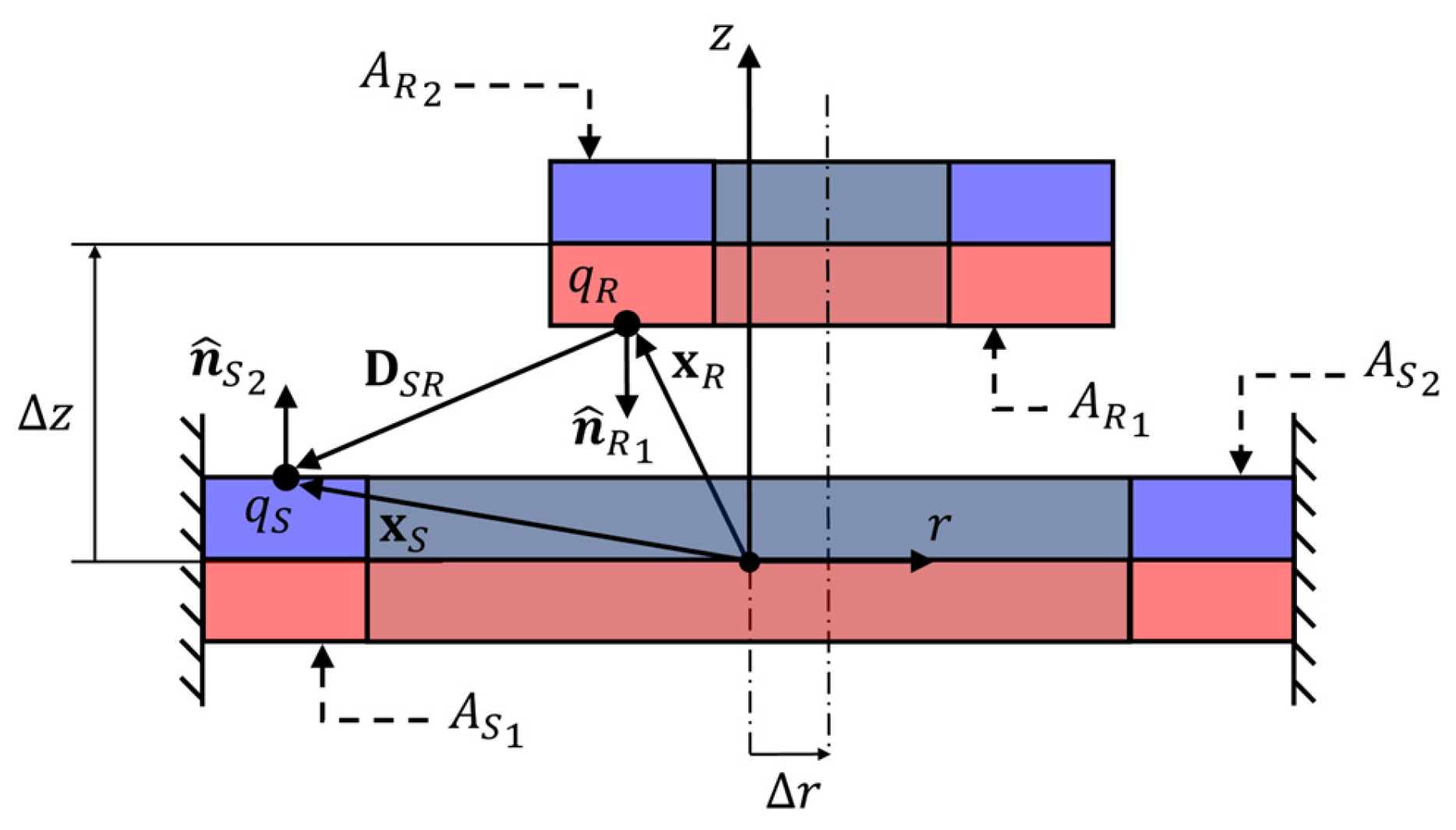
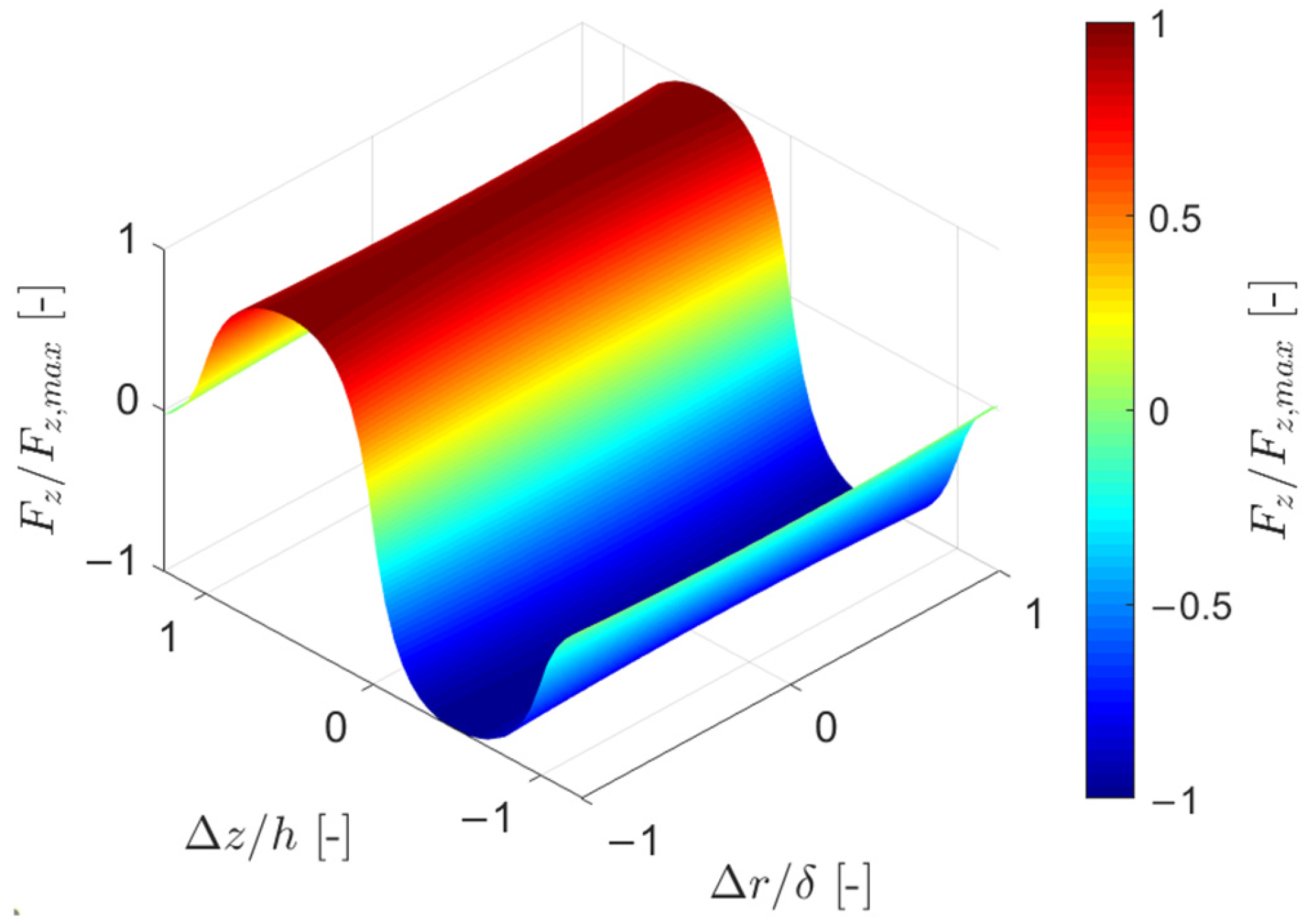
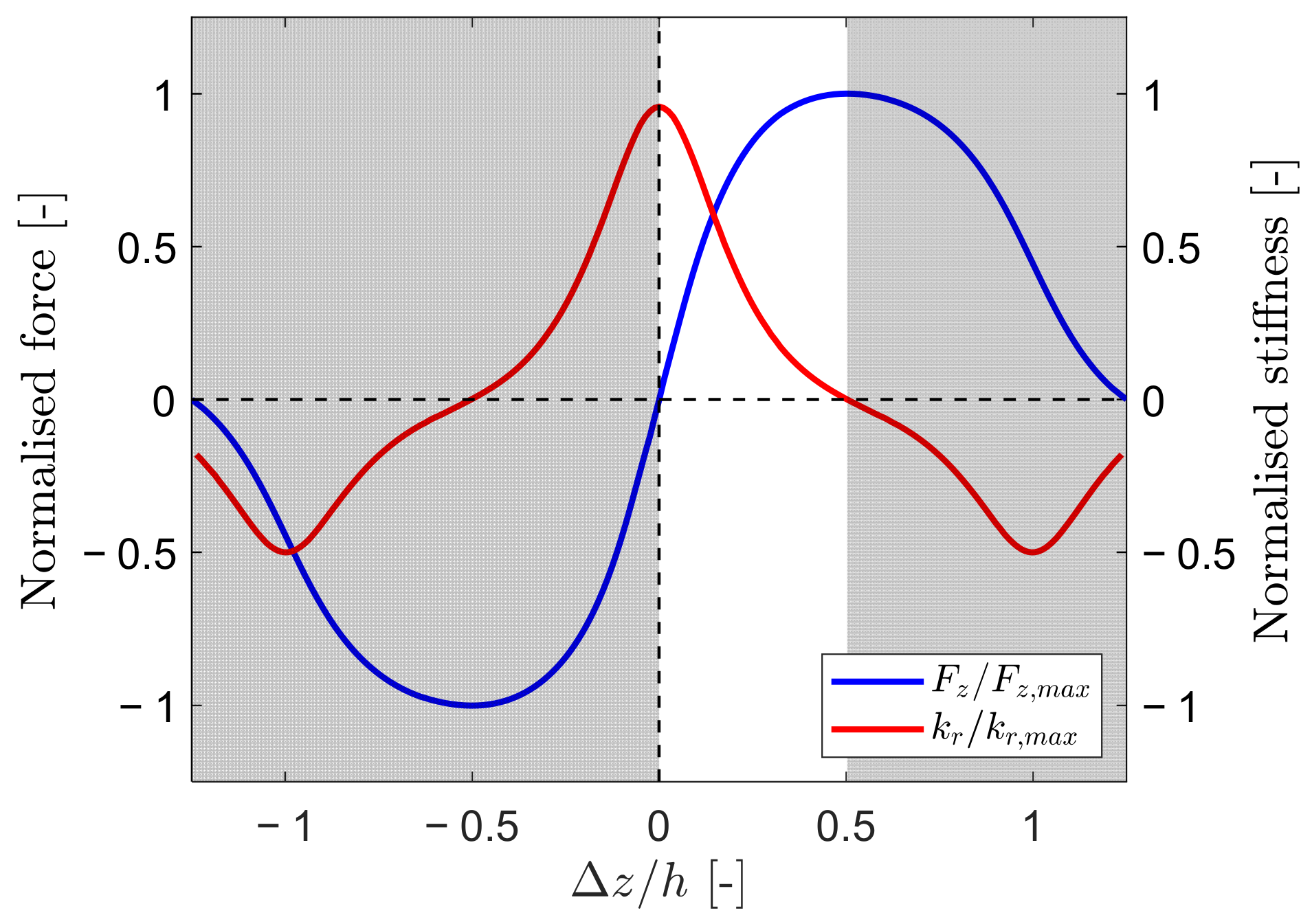
2. PMB Model
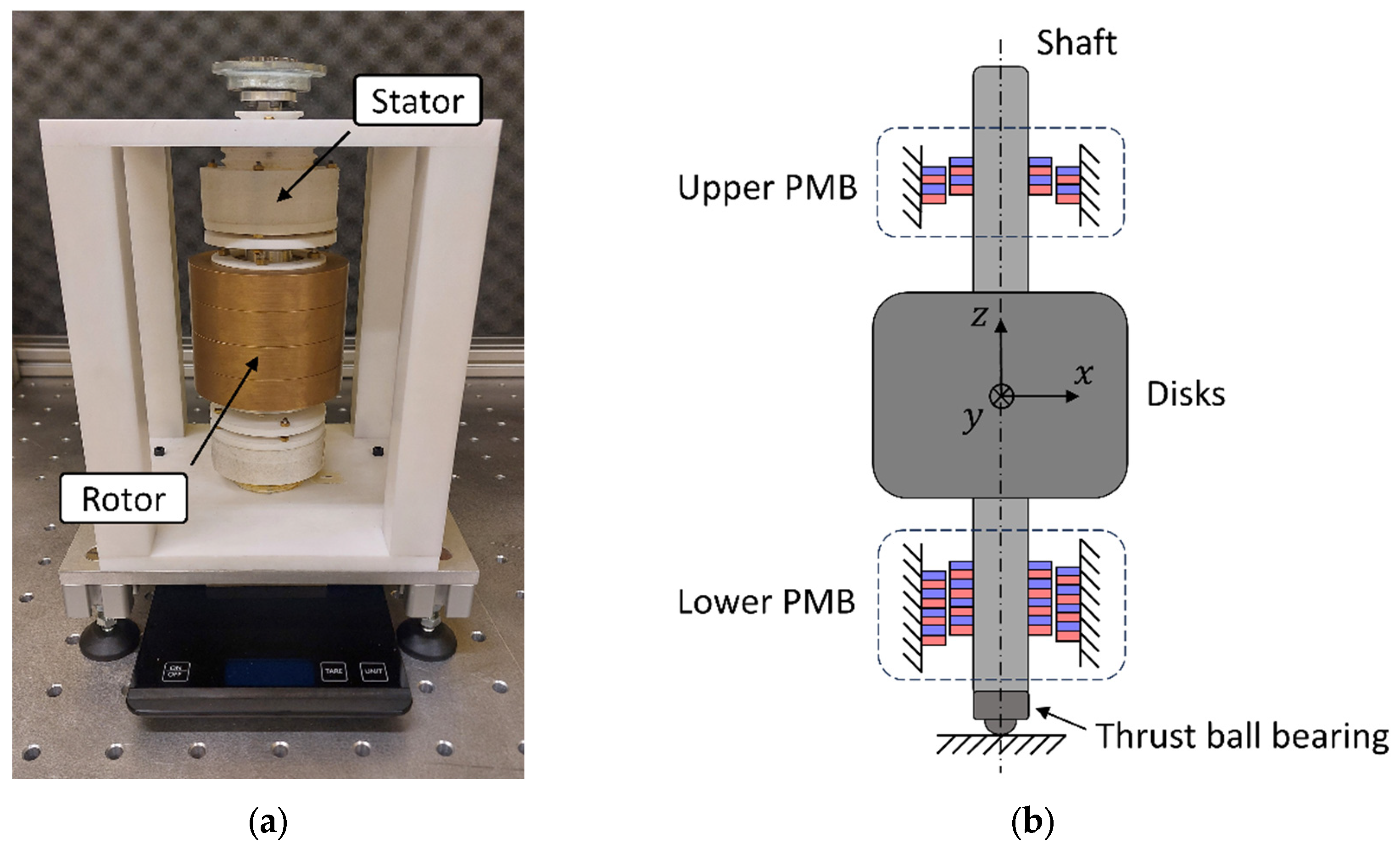
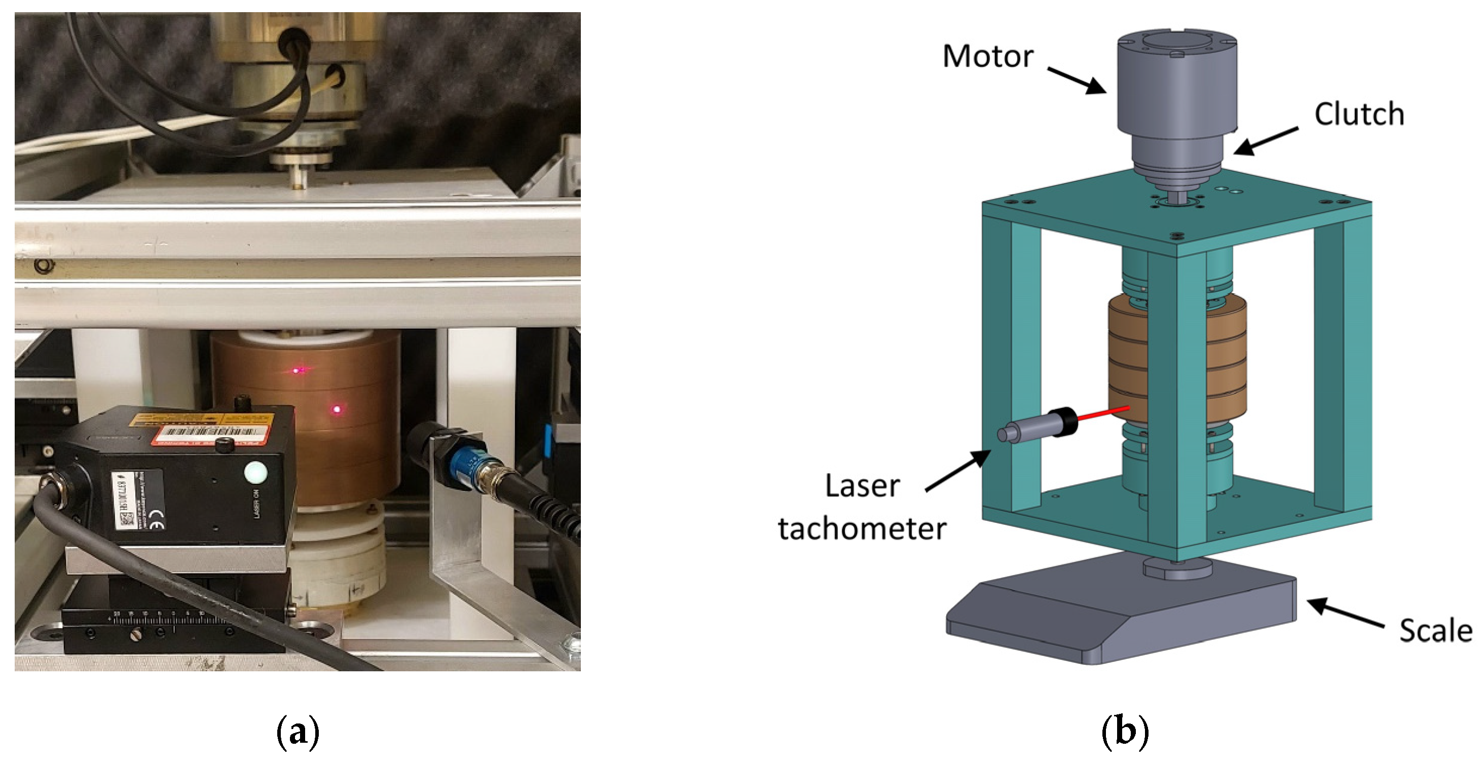
3. Experimental Setup
4. Results and Discussion
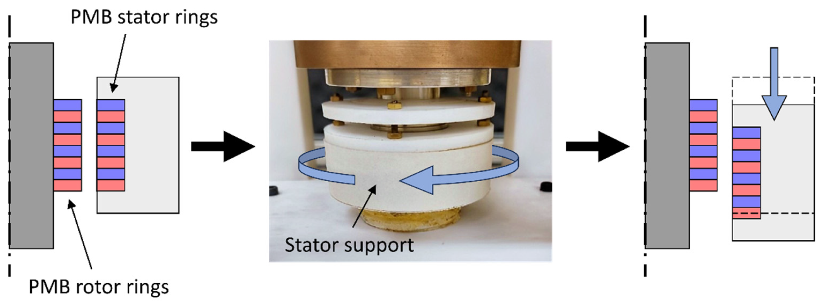
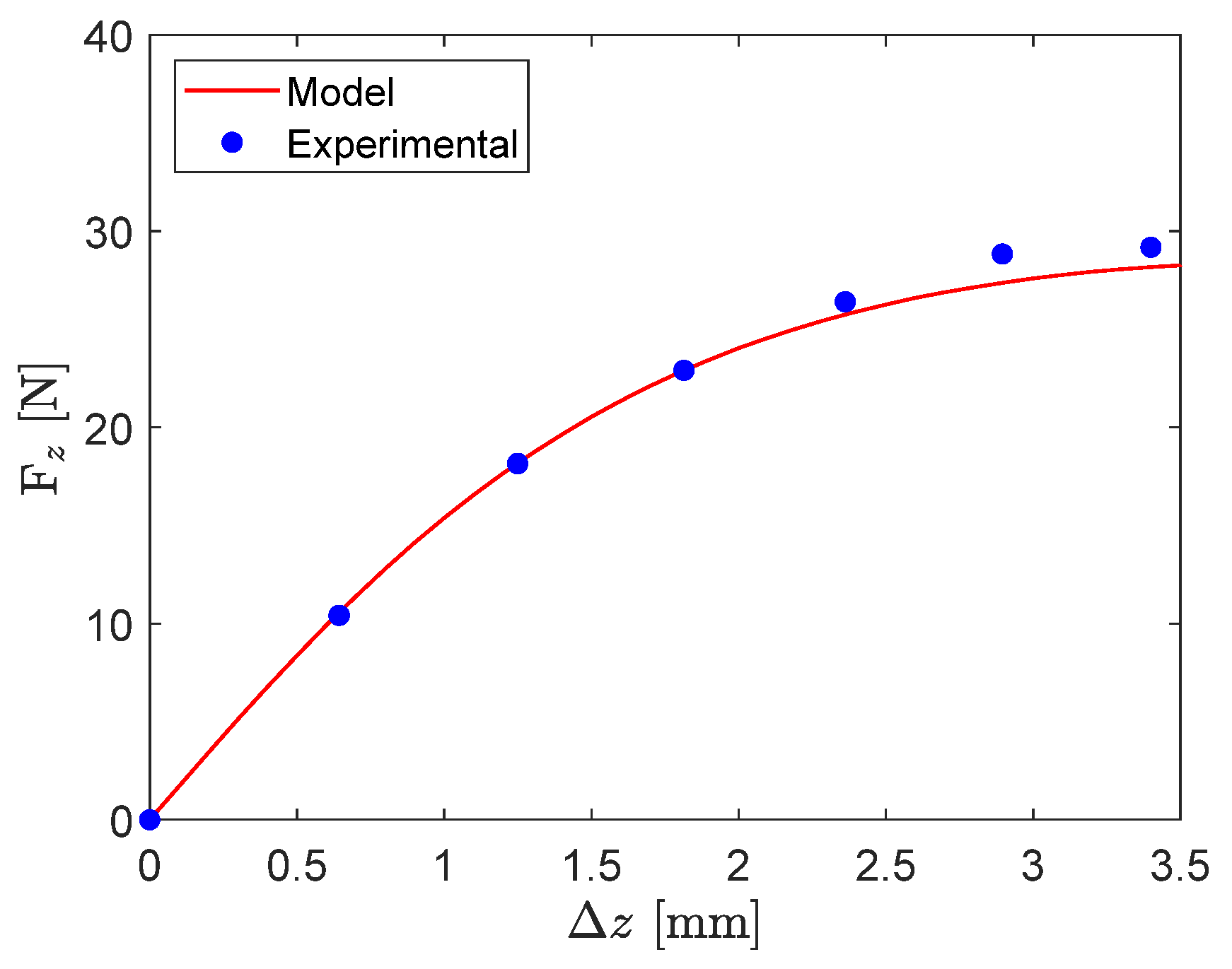
4.1. Static Tests
- The starting position of the tests corresponds to axial position of the stator ring at which is null; is set equal to zero and the scale measures a force equal to the rotor weight force;
- The stator support is progressively rotated to vary its vertical position, moving downward by steps of , up to the maximum upward value, corresponding to the condition where a further rotation of the stator support causes a decrease in .
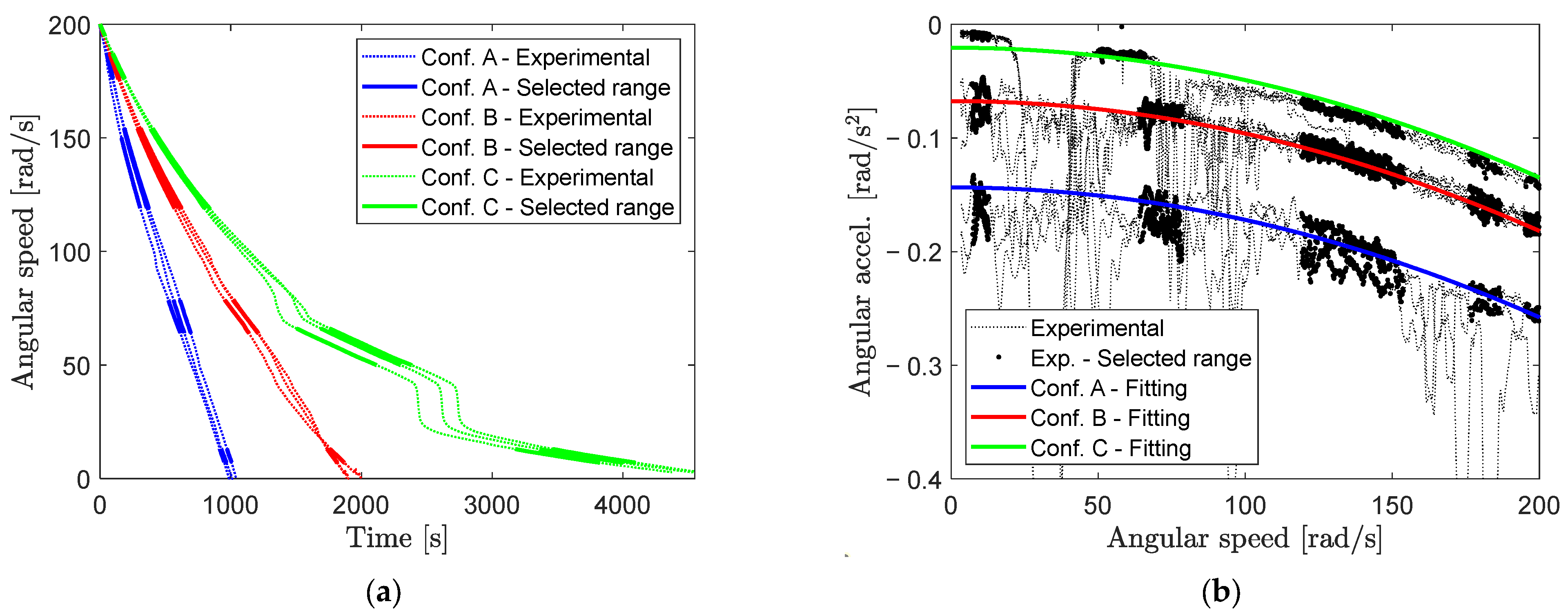
4.2. Dynamic Tests
- The rotor is accelerated, then it is decoupled from the actuation system and left freely rotating, so that its angular speed progressively decreases;
- The angular speed is acquired from rad/s until the rotor stops.
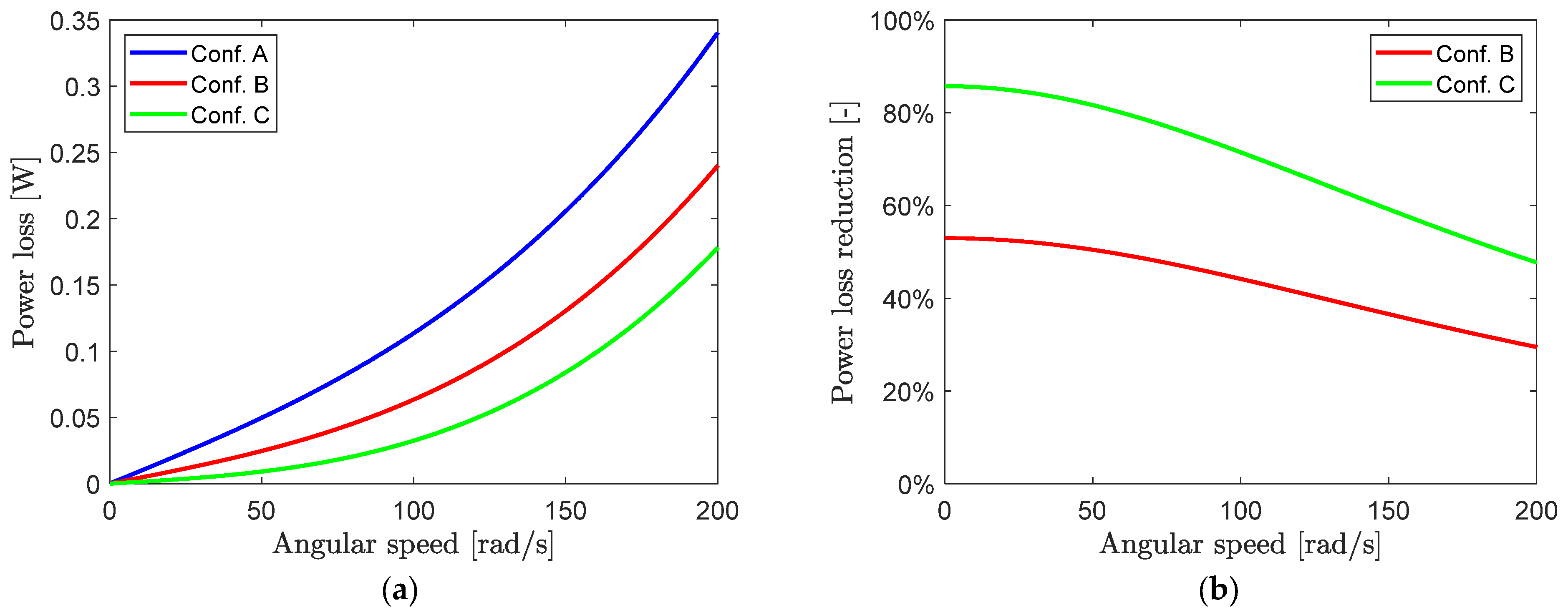
- At low speed, the power loss percentage reduction tends to the values of the weight percentage compensation listed in Table 2 because the aerodynamic effect tends to zero;
- At high speed, the aerodynamic losses are the most relevant; the percentage reduction in configuration C is still high and equal to 47.7% at 200 rad/s.
5. Conclusions
Author Contributions
Funding
Institutional Review Board Statement
Informed Consent Statement
Data Availability Statement
Conflicts of Interest
Nomenclature
| Symbol | Description |
| rotor mass [kg] | |
| polar moment of inertia [kg m2] | |
| gravitational acceleration [m/s2] | |
| rotor angular speed [rad/s] | |
| PMB ring residual magnetic induction [T] | |
| vacuum permeability [H/m] | |
| magnet infinitesimal surface [m2] | |
| magnet infinitesimal surface charge [C] | |
| surface charge density [A/m] | |
| outward unit normal to the PMB ring plane surfaces [-] | |
| outward unit normal to the lower and upper surfaces of the PMB stator ring [-] | |
| outward unit normal to the lower and upper surfaces of the PMB rotor ring [-] | |
| position vector of an infinitesimal surface charge [m] | |
| relative position vector between two infinitesimal surface charges [m] | |
| , | axial and radial offsets between the PMB rotor and stator rings [m] |
| , | lower and upper plane surface of the PMB stator ring [m2] |
| , | lower and upper plane surface of the PMB rotor ring [m2] |
| overall force between PMB stator and rotor rings [N] | |
| , | PMB axial and radial force components [N] |
| axial forces of the lower and upper PMB [N] | |
| magnetic flux density [T] | |
| , , | magnetic flux density in -, -, and - directions [T] |
| magnetisation [A/m] | |
| m | magnetic moment [A m2] |
| , , | magnetic moment in -, -, and - directions [A m2] |
| magnetic field intensity [A/m] | |
| electric field [V/m] | |
| current density [A/m-2] | |
| vacuum permittivity [F/m] | |
| , | PMB axial and radial stiffness [N/m] |
| PMB thickness [m] | |
| PMB radial airgap [m] | |
| Coulomb rolling contact friction coefficient [-] | |
| ball radius of the ball thrust bearing [m] | |
| contact reaction force [N] | |
| k | angular speed exponent for aerodynamic power loss terms [-] |
| aerodynamic power loss coefficients [Nm sk] | |
| total power losses [W] | |
| resisting torque [Nm] | |
| driving torque [Nm] | |
| power losses due to contact friction effect [W] | |
| power losses due to aerodynamic effect [W] | |
| magnetic potential energy [J] |
Appendix A

| Characteristic | Property | Value |
|---|---|---|
| Rotor | m, mass [kg] | |
| l, length [mm] | ||
| It, transversal moment of inertia [kg m2] | ||
| Ip, polar moment of inertia [kg m2] | ||
| Stator magnets | dint, internal diameter [mm] | |
| dext, external diameter [mm] | ||
| hr, ring height z [mm] | ||
| Br, residual magnetic induction [T] | ||
| Rotor magnets | dint, internal diameter [mm] | |
| dext, external diameter [mm] | ||
| hr, ring height z [mm] | ||
| Br, residual magnetic induction [T] |
Appendix B
References
- Slininger, T.S.; Chan, W.; Severson, E.L.; Jawdat, B. An Overview on Passive Magnetic Bearings. In Proceedings of the IEEE International Electric Machines & Drives Conference (IEMDC), Hartford, CN, USA, 17–20 May 2021; pp. 1–8. [Google Scholar] [CrossRef]
- Maslen, E.H.; Schweitzer, G. Magnetic Bearings; Springer: Berlin/Heidelberg, Germany, 2009. [Google Scholar]
- Ebrahimi, R.; Ghayour, M.; Khanlo, H.M. Nonlinear dynamic analysis and experimental verification of a magnetically supported flexible rotor system with auxiliary bearings. Mech. Mach. Theory 2018, 121, 545–562. [Google Scholar] [CrossRef]
- Bonisoli, E.; Venturini, S.; Cavallaro, S.P. Nonlinear characterisation of a rotor on passive magnetic supports. Int. J. Mech. Control 2022, 23, 121–128. [Google Scholar]
- Zhou, J.; Fang, Z.; He, S.; Zhang, Q. Modelling and stability analysis of the permanent magnetic bearing-rotor system under base excitation. Arch. Appl. Mech. 2025, 95, 29. [Google Scholar] [CrossRef]
- Safaeian, R.; Heydari, H. Comprehensive comparison of different structures of passive permanent magnet bearings. IET Electr. Power Appl. 2018, 12, 179–187. [Google Scholar] [CrossRef]
- Li, X.; Palazzolo, A. A review of flywheel energy storage systems: State of the art and opportunities. J. Energy Storage 2022, 46, 103576. [Google Scholar] [CrossRef]
- Schweitzer, G. Applications and Research Topics for Active Magnetic Bearings. IUTAM Bookser. 2010, 1011, 263–273. [Google Scholar] [CrossRef]
- Roy, H.K.; Das, A.S.; Dutt, J.K. An efficient rotor suspension with active magnetic bearings having viscoelastic control law. Mech. Mach. Theory 2016, 98, 48–63. [Google Scholar] [CrossRef]
- Supreeth, D.K.; Bekinal, S.I.; Chandranna, S.R. An Overview on Electrodynamic Bearings. IEEE Access 2022, 10, 57437–57451. [Google Scholar] [CrossRef]
- Amati, N.; De Leépine, X.; Tonoli, A. Modeling of Electrodynamic Bearings. J. Vib. Acoust. 2008, 130, 061007. [Google Scholar] [CrossRef]
- Earnshaw, S. On the nature of the molecular forces which regulate the constitution of the luminiferous ether. Trans. Camb. Philos. Soc. 1848, 7, 97–112. [Google Scholar]
- Fang, J.; Le, Y.; Sun, J.; Wang, K. Analysis and Design of Passive Magnetic Bearing and Damping System for High-Speed Compressor. IEEE Trans. Magn. 2012, 48, 2528–2537. [Google Scholar] [CrossRef]
- Filatov, A.V.; Maslen, E.H. Passive Magnetic Bearing for Flywheel energy storage systems. IEEE Trans. Magn. 2001, 37, 3913–3924. [Google Scholar] [CrossRef]
- Dergachev, P.; Kosterin, A.; Kurbatova, E.; Kurbatov, P. Flywheel energy storage system with magnetic hts suspension and embedded in the flywheel motor-generator. In Proceedings of the IEEE International Power Electronics and Motion Control Conference (PEMC), Varna, Bulgaria, 25–28 September 2016. [Google Scholar] [CrossRef]
- Premkumar, T.M.; Mohan, T.; Sivamani, S. Design and Analysis of a Permanent Magnetic Bearing for Vertical Axis Small Wind Turbine. Energy Procedia 2017, 117, 291–298. [Google Scholar] [CrossRef]
- Van Verdeghem, J.; Dehez, B. Fully Passively Levitated Self-Bearing Machine Implemented Within a Reaction Wheel. IEEE Trans. Ind. Appl. 2021, 57, 5782–5795. [Google Scholar] [CrossRef]
- Filion, G.; Ruel, J.; Dubois, M.R. Reduced-Friction Passive Magnetic Bearing: Innovative Design and Novel Characterization Technique. Machines 2013, 1, 98–115. [Google Scholar] [CrossRef]
- Bekinal, S.I.; Anil, T.R.; Jana, S. Analysis of axially magnetized permanent magnet bearing characteristics. Prog. Electromagn. Res. B 2012, 44, 327–343. [Google Scholar] [CrossRef]
- Furlani, E.P. Permanent Magnet and Electromechanical Devices: Materials, Analysis, and Applications; Elsevier: Amsterdam, The Netherlands, 2001. [Google Scholar]
- Santra, T.; Roy, D.; Yamada, S. Calculation of Force between Two Ring Magnets Using Adaptive Monte Carlo Technique with Experimental Verification. Prog. Electromagn. Res. 2016, 49, 181–193. [Google Scholar] [CrossRef]
- Chalageri, G.R.; Bekinal, S.I.; Doddamani, M. Dynamic Analysis of 650 W Vertical-Axis Wind Turbine Rotor System Supported by Radial Permanent Magnet Bearings. Eng. Proc. 2023, 59, 56. [Google Scholar] [CrossRef]
- Dagnaes-Hansen, N.A.; Santos, I.F. Permanent magnet thrust bearings for flywheel energy storage systems: Analytical, numerical, and experimental comparisons. Proc. Inst. Mech. Eng. Part C J. Mech. Eng. Sci. 2019, 233, 5280–5293. [Google Scholar] [CrossRef]
- Popescu, A.; Houpert, L.; Olaru, D.N. Four approaches for calculating power losses in an angular contact ball bearing. Mech. Mach. Theory 2020, 144, 103669. [Google Scholar] [CrossRef]
- Cavallaro, S.P.; Venturini, S.; Bonisoli, E. Nonlinear dynamics of a horizontal rotor with asymmetric magnetic supports. Int. J. Non-Linear Mech. 2024, 165, 104764. [Google Scholar] [CrossRef]
- Chen, H.; Zhong, S.; Lu, Z.; Chen, Y.; Han, J.; Wang, C. Analysis on multi-mode nonlinear resonance and jump behavior of an asymmetric rolling bearing rotor. Arch. Appl. Mech. 2021, 91, 2991–3009. [Google Scholar] [CrossRef]
- Venturini, S.; Cavallaro, S.P.; Vigliani, A. Windage loss characterisation for flywheel energy storage system: Model and experimental validation. Energy 2024, 307, 132641. [Google Scholar] [CrossRef]
- Bassani, R. Earnshaw (1805–1888) and Passive Magnetic Levitation. Meccanica 2006, 41, 375–389. [Google Scholar] [CrossRef]
- Bassani, R. Magnetoelastic Stability of Magnetic Axial Bearings. Tribol. Lett. 2013, 49, 397–401. [Google Scholar] [CrossRef]
| Axial Offset Δz | Error % |
|---|---|
| [mm] | [-] |
| 0 | - |
| 0.6 | 1.9 |
| 1.2 | 0.3 |
| 1.8 | 0.1 |
| 2.4 | 2.2 |
| 2.9 | 5.0 |
| 3.4 | 3.7 |
| PMB Configuration | Axial Offset Δz | Weight Percentage Compensation | |
|---|---|---|---|
| [mm] | [N] | [-] | |
| A | 0 | 49.0 | 0% |
| B | 0.8 | 24.1 | 49.2% |
| C | 1.6 | 7.3 | 85.1% |
Disclaimer/Publisher’s Note: The statements, opinions and data contained in all publications are solely those of the individual author(s) and contributor(s) and not of MDPI and/or the editor(s). MDPI and/or the editor(s) disclaim responsibility for any injury to people or property resulting from any ideas, methods, instructions or products referred to in the content. |
© 2025 by the authors. Licensee MDPI, Basel, Switzerland. This article is an open access article distributed under the terms and conditions of the Creative Commons Attribution (CC BY) license (https://creativecommons.org/licenses/by/4.0/).
Share and Cite
Vigliani, A.; Cavallaro, S.P.; Venturini, S. Modelling and Experimental Testing of Passive Magnetic Bearings for Power Loss Reduction. Appl. Sci. 2025, 15, 4149. https://doi.org/10.3390/app15084149
Vigliani A, Cavallaro SP, Venturini S. Modelling and Experimental Testing of Passive Magnetic Bearings for Power Loss Reduction. Applied Sciences. 2025; 15(8):4149. https://doi.org/10.3390/app15084149
Chicago/Turabian StyleVigliani, Alessandro, Salvatore Paolo Cavallaro, and Simone Venturini. 2025. "Modelling and Experimental Testing of Passive Magnetic Bearings for Power Loss Reduction" Applied Sciences 15, no. 8: 4149. https://doi.org/10.3390/app15084149
APA StyleVigliani, A., Cavallaro, S. P., & Venturini, S. (2025). Modelling and Experimental Testing of Passive Magnetic Bearings for Power Loss Reduction. Applied Sciences, 15(8), 4149. https://doi.org/10.3390/app15084149