1. Introduction
AMBs have been widely used in high-speed rotating machinery such as blowers, molecular pumps and flywheel energy storage due to their advantages of having no friction and active controllability [
1,
2,
3,
4,
5]. However, the mass imbalance of the rotor is inevitable. Due to the existence of the above imbalance, a centrifugal force at the same frequency as the rotor speed is generated as the rotor rotates, which causes the rotor to vibrate. In high-speed rotating machinery, rotor mass imbalance is the main cause of rotor vibration [
6]. Excessive vibration not only affects the suspension accuracy of the rotor but also affects the AMB system.
For the rotor vibration of traditional rotating machinery, a dynamic balance machine is usually used for dynamic balance correction, and rotor vibration is reduced by reducing the unbalanced mass of the rotor. This method is offline dynamic balance, which not only makes it time-consuming to disassemble and transport the rotor but also affects the accuracy of dynamic balance correction because the dynamic balance environment is different from the working environment.
To solve the vibration problem of the AMB rotor, researchers have conducted many studies and proposed many solutions. Zhou et al. proposed an online unbalance compensation method which integrates a least mean square (LMS) algorithm and ICM [
7]. Through real-time calculation and adjustment, the method can effectively identify and compensate for the imbalance during rotor operation, thereby reducing vibration and improving system stability. The experimental results show that the method can significantly reduce rotor vibration at different rotational speeds and has strong engineering practicability. Mao et al. devised a real-time polygon iterative search algorithm with a variable step size based on the rotor unbalance coefficient for an unbalanced compensator [
8]. The AMB produces a controlled force equal in magnitude and opposite in phase to the rotor unbalance force. But this method requires a phase sensor to confirm the reference phase. Peng et al. proposed a synchronous vibration suppression method based on phase advance compensation for variable speed maglev flywheel systems [
9]. By designing a phase advance compensator, the synchronous vibration of the flywheel is solved. Li et al. designed an improved resonant controller to solve the vibration problem caused by displacement harmonics in the AMB rotor system [
10]. The improved controller enhances the system’s ability to suppress harmonic interference, effectively reduces vibration and improves the stability and dynamic performance of the system. Gong et al. proposed a synchronous unbalanced vibration suppression method for maglev high-speed motors [
11]. The polarity switching tracking filter is used to identify the synchronous vibration, and then the disturbance observer is used to observe and compensate for the disturbance in the resonance range, effectively suppressing the synchronous vibration in the whole speed range. Cui et al. applied repetitive control to the AMB rotor system to suppress harmonic vibration torque, which significantly reduced the vibration level of the system under harmonic interference [
12]. The effectiveness and applicability of the strategy are verified by simulation and experiment. He et al. proposed a cascaded phase-shifted notch filter [
13]. With high-speed maglev centrifugal compressor as the research object, harmonic vibration is effectively suppressed and the stability of system operation is improved through the phase compensation and notch wave property of a cascade filter. Liu et al. studied the control method of a synchronous current in an active magnetic bearing system, focusing on the influence of radial displacement inconsistency on the system [
14]. The control strategy effectively reduces the current fluctuation caused by displacement inconsistency and improves the stability and performance of the system. Zhang et al. designed an integrated AMB controller, which consists of parallel co-frequency ANF and cascaded multi-frequency improved DTNFs [
15]. And they proposed a bandwidth factor rectification method for the ANF based on displacement stiffness perturbations. The robustness of the method at different rotational speeds is verified by simulation and experiment respectively, and the vibration displacement of the rotor is significantly reduced. Taha et al. used a digital twin to simulate the performance of a magnetic bearing system in real time [
16]. The comparison between simulation data and experimental data verified the effectiveness of this method. This technology can be used to identify problems in the magnetic bearing system before a failure occurs. Gao et al. proposed an optimized active disturbance rejection control (ADRC) algorithm to enhance the speed stability of permanent magnet synchronous motors (PMSMs) [
17]. The method makes up for the deficiency of typical ADRC through the fusion of multiple control quantities. Simulations and experiments verified the robustness of the method. Dragoi et al. provided a method to resolve the problem of improper counterweight angles [
18]. A rotary device can be installed to enable the relative orientation of the counterweight plate against the rotor to be adjusted.
In conclusion, researchers have proposed many solutions to the vibration problem of AMB rotors. But most of the methods are from the perspective of vibration suppression, ignoring the characteristics of the rotor itself. When the rotor imbalance is large, it is difficult to make the rotor run smoothly through external suppression. With the help of the system’s own control module and monitoring module, a dynamic balance correction method for the AMB rotor based on ANF and ICM is proposed in this paper, which aims to reduce the vibration in the system by reducing the mass imbalance of the rotor itself.
The remaining content of this paper is arranged as follows. The second part introduces the AMB system and establishes the dynamic model of the system. The third part introduces the realization process of the dynamic balance correction method in this paper, including the tracking and calculation of the displacement signal by using the improved ANF, the solution of the dynamic balance counterweight by using the ICM and the treatment of the residual imbalance. In the fourth part, the dynamic balance correction method is verified by simulation. The fifth part further verifies the dynamic balance effect of the method in this paper through experiments. The conclusion is in the last part.
2. Active Magnetic Bearing Rotor System Model
The AMB rotor system is an integrated electromechanical system, including an AMB, rotor, controller, power amplifier, displacement sensors and other modules. The system can monitor the state of the rotor through the displacement sensors and perform real-time closed-loop control of the rotor.
Affected by various factors, the imbalance of the magnetic bearing rotor is inevitable. The unbalanced mass will cause the rotor center of mass to shift, resulting in a centrifugal force at the same frequency as the rotor speed.
Figure 1 is a schematic diagram of AMB rotor structure. The coordinate system is established with the geometric center
O,
G is the rotor center of mass,
la is the distance from the plane center of the AMB at the
A end to the rotor center of mass,
lb is the distance from the plane center of the AMB at the
B end to the rotor center of mass, and
l is the distance from the AMB at both ends.
θx is the angle at which the rotor rotates counterclockwise in the
yz plane and
θy is the angle at which the rotor rotates counterclockwise in the
xz plane.
fax,
fbx,
fay and
fby are the levitation forces exerted on the rotor by the AMB at both ends of
A and
B in the
x and
y directions, respectively.
The displacements at both ends of the rotor are
xa,
ya,
xb and
yb, respectively.
xc and
yc are the shifts of the center of mass in the
x and
y directions from the geometric center, respectively. The displacement of both ends has the following relationship with the offset of the center of mass.
We can write this in its matrix form, as shown in Equation (2).
is the rotor mass characteristic matrix, is the displacement of the rotor in all directions. is the transformation matrix.
According to Newton’s second law and the law of rotor rotation at fixed point, the motion equation of the AMB rotor can be obtained, as shown in Equation (3).
where
m is the mass of the rotor,
ω is the rotational speed of the rotor and
Ix,
Iy and
Iz are about the
x-axis,
y-axis and
z-axis of inertia.
We can write this in its matrix form, as shown in Equation (4).
is the rotor mass characteristic matrix, is the gyro matrix and , is the electromagnetic force matrix of the rotor.
When the rotor is near the equilibrium point, the linear expression of the AMB electromagnetic force can be obtained as shown in Equation (5) [
19].
where
f is the electromagnetic force,
ki is the current stiffness coefficient,
kx is the displacement stiffness coefficient,
i is the coil current and
x is the rotor displacement.
The electromagnetic force of four active magnetic bearings is written in matrix form, as shown in Equation (6).
In the equation, is the electromagnetic force matrix, is the current stiffness matrix, is the displacement stiffness matrix, is the coil current matrix and is the displacement matrix.
The equation of motion of the four-degrees-of-freedom AMB rotor system can be obtained by bringing Equations (2) and (6) into Equation (4), as shown in Equation (7).
When the AMB rotor is slender and the working speed is low, the distribution characteristics of the rotor’s moment of inertia substantially reduce the contribution of gyroscopic torque to the system’s dynamic response. Meanwhile, the angular momentum rate under low-speed operating conditions is insufficient to excite significant gyroscopic effects. Based on this physical characteristic, the gyro coupling term can be ignored. Therefore, Equation (7) can be simplified to Equation (8).
Equation (8) is expanded into Equation (9).
Equation (10) can be obtained by bringing the data in
Table 1 into Equation (9).
It can be seen from Equation (10) that the movement of the AMB rotor in the x (y) direction is independent of the force in the y (x) direction. The movement of one end of the AMB rotor in the x (y) direction is little affected by the force in the x (y) direction at the other end of the rotor. Therefore, for a rigid rotor, it can be considered that the motion of the AMB rotor in the four degrees of freedom is decoupled, and the four degrees of freedom can be decoupled.
3. Implementation of Dynamic Balance Method
In this paper, a dynamic balance correction method of an AMB rotor based on improved adaptive notch filter (ANF) and ICM is proposed. The method uses ANF to track the rotor displacement signal in real time, calculate the amplitude and phase of the displacement signal and obtain the rotor displacement vibration vector. Then, according to the displacement vibration vector and the size and position of the counterweight, the correction mass is calculated by the ICM. Combined with the actual situation of the AMB rotor weight plate, the correction quality is reasonably distributed, and multiple corrections are carried out to achieve the dynamic balance of the AMB rotor. The schematic diagram of the dynamic balance correction method is shown in
Figure 2.
3.1. Adaptive Notch Filter
In this paper, an amplitude and phase solution method based on improved ANF is adopted. The method has a simple structure and good tracking performance.
The input signal, as shown in Equation (11), is a single sinusoidal signal and contains a DC component, where
A0 is the DC component,
A is the amplitude of the sinusoidal signal,
ω is the frequency and
φ is the initial phase.
The differential equation of the improved ANF is shown in Equation (12) [
20,
21].
where
is the estimated frequency of
u(t), which is equal to the actual frequency
ω.
is the instantaneous value of
u(t).
and
are ANF parameters, which determine the steady state accuracy and convergence rate of ANF, respectively.
N,
μ and
λ are positive real numbers that can be adjusted according to the signal frequency.
is the calculated DC component.
Equation (13) is the solution to the above equations.
From Equation (13), it can be known that
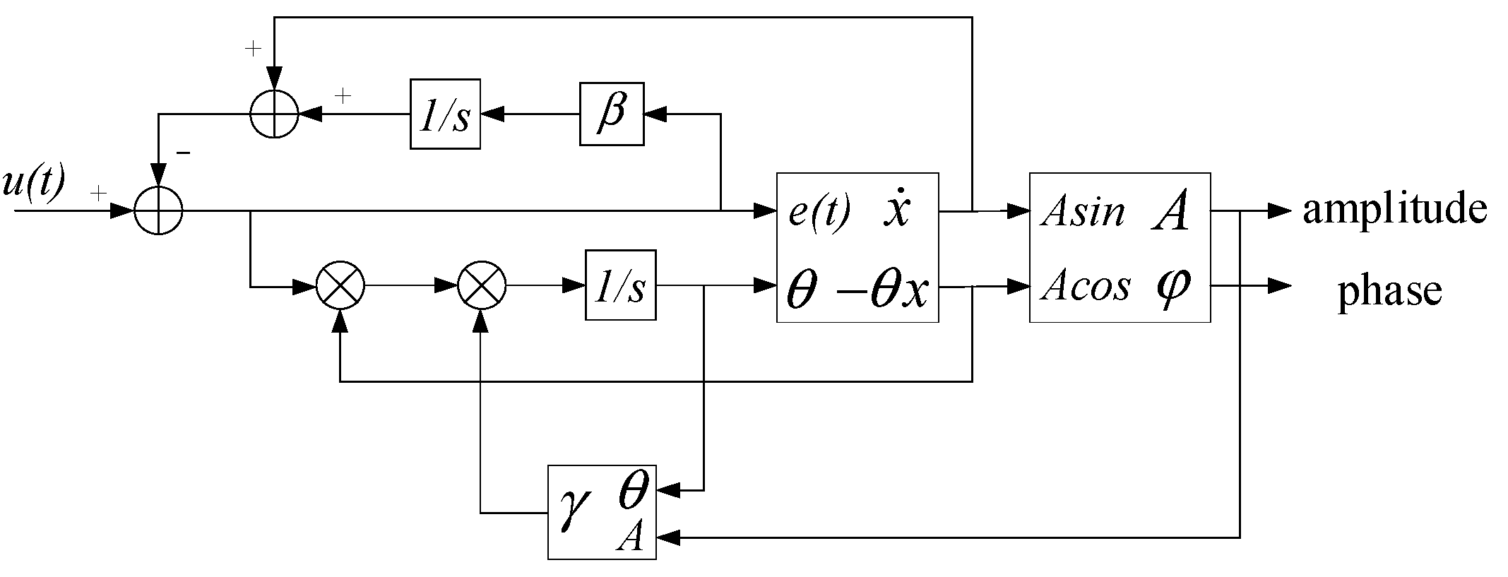
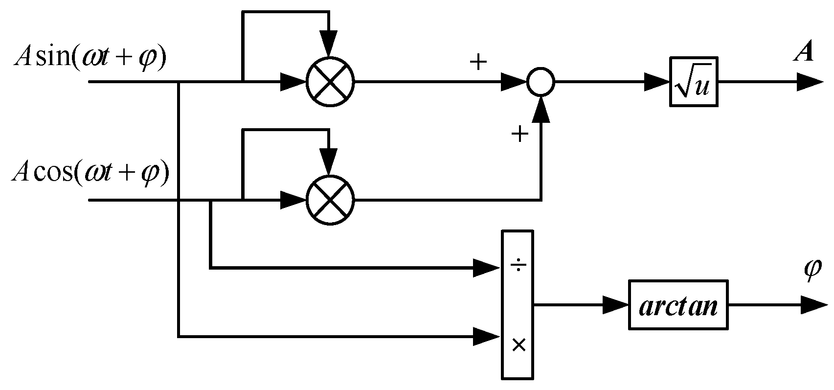
is the orthogonal component of the input signal. According to the input signal and the orthogonal components of the input signal, the amplitude and phase information of the input signal can be obtained. The calculation formula is shown in Equations (14) and (15).
The schematic diagram of calculating amplitude and phase based on the improved ANF is shown in
Figure 3.
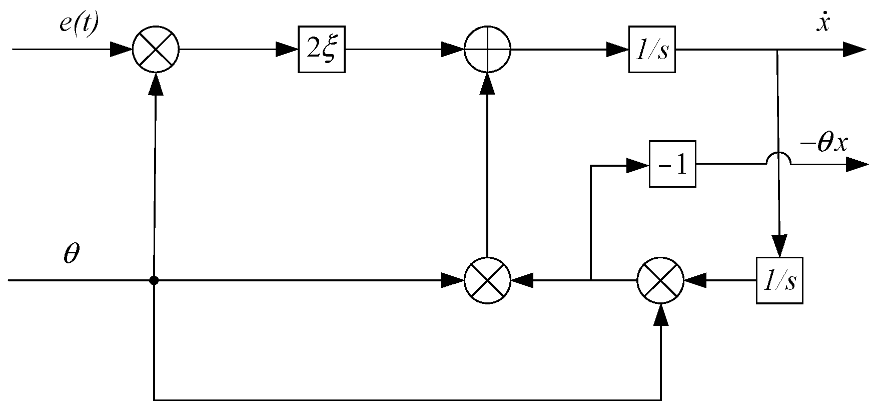
Figure 4 shows the substructure of the ANF.
Figure 5 shows the amplitude and phase calculation substructure.
Set the ANF parameters according to
Table 2 to track the displacement signal.
The tracking effect of the improved ANF algorithm on the collected signal is shown in
Figure 6. It can be seen from the figure that the algorithm can accurately track the displacement signal of the same frequency as the rotor speed.
3.2. Influence Coefficient Method
In this paper, based on the monitoring and control function of the AMB rotor system, the dynamic balance correction of the rotor is carried out by using the ICM.
ICM is one of the most commonly used dynamic balance correction methods. The essence of the method is to calculate the counterweight mass required to offset the initial imbalance by solving the linear relationship between the test weight and the rotor displacement response (influence coefficient). Mass blocks can be added to the rotor to solve the problem of rotor mass imbalance [
22,
23]. The specific implementation process is as follows.
The rotor is driven to a stable rotational speed ω0, and the displacement signals at the A and B ends of the rotor are collected through the displacement sensor. The improved ANF is used to calculate the amplitude and phase information of the displacement signal, and the initial vibration displacement vectors Da0 and Db0 are obtained.
We can increase the test weight mass MA at end A and drive the rotor to a stable speed ω0. The displacement signals of the A and B ends are collected by the displacement sensor, and the vibration displacement vectors Da1 and Db1 on the two measurement surfaces are obtained.
Next, we can remove the mass MA, increase the test weight mass MB at the B end and drive the rotor to a stable speed ω0. The displacement signals of A end and B end are collected by the displacement sensor and the vibration displacement vectors Da2 and Db2 on the two measuring surfaces are obtained.
Where
MA and
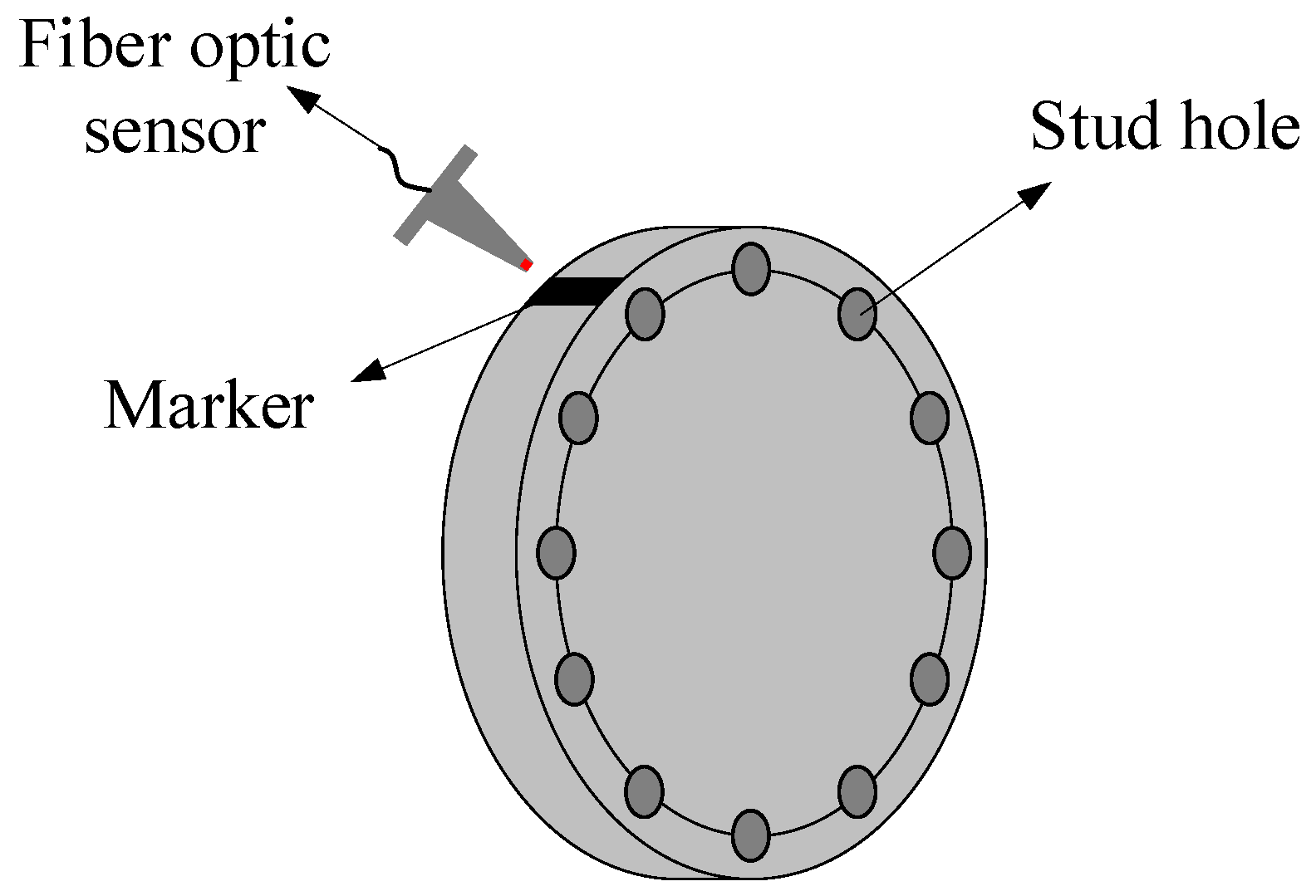
MB are both vectors. In order to unify the zero phase of the vibration displacement vector and the counterweight vector, a fiber optical sensor is introduced in this paper.
Figure 7 is a schematic diagram of the counterweight plate and the fiber optical sensor.
The counterweight plate has a circle of stud holes, which can be counterweighted by inserting studs of different lengths. A stud hole can be selected as the starting position, which is the zero phase of the counterweight vector. The marker can be pasted on the circumference at the same phase as the starting position. The fiber optic sensor encounter marker generates a rising edge signal. During the rotation of the rotor, the fiber optic sensor generates a square wave of the same frequency as the rotational speed. Using the rising edge of the square wave as the zero phase of the displacement vector, the unity of the zero phase of the counterweight vector and the displacement vector is realized.
The influence coefficient is calculated by using the above displacement vibration vector and test weight mass
MA and
MB. The calculation formula is as Equation (16).
According to the influence coefficient and the initial vibration displacement vector, the increased counterweight masses
MA0 and
MB0 at both ends of
A and
B are calculated. The calculation formula is as Equation (17).
3.3. Corrected Mass Distribution and Residual Unbalance Treatment
Due to the limitation of the number of stud holes on the counterweight plate, the length and quality of the stud, the specific amplitude and phase counterweight vector cannot be satisfied. Therefore, the counterweight vector can be decomposed to obtain the appropriate weight on the existing stud hole.
In addition, there are various errors in the dynamic balance correction process. For example, due to the assembly error caused by the installation of components such as rotors and sensors, the marker cannot be aligned with the center of the starting position stud hole, resulting in a phase error in which the zero phase of the counterweight vector and the displacement vector is not uniform. Ultimately, it causes an error between the actual counterweight vector and the theoretically calculated value. There must be residual imbalance in the system after one dynamic balance correction. The influence coefficient can be calculated again and the rotor can be corrected for dynamic balance several times until the accuracy requirements are met.
4. Simulation Analysis
In order to verify the effectiveness of the dynamic balance correction method in this paper, the rotor dynamic balance correction simulations are carried out at different speeds. The simulation parameters are shown in
Table 1. The initial unbalance parameters of the rotor system are as follows. The unbalanced mass
me is 100 g, the distance to the centroid
le is 30 mm, the phase is 30 degrees and the eccentricity
e is 20 mm.
The method presented in this paper only requires trial weight and counterweight calculation to be performed at a constant speed. After applying the dynamic balance correction method to the rotor, the vibration displacement in the rigid rotor region will be reduced. Therefore, in the simulation analysis, the dynamic balance effects at two speeds of 1800 r/min and 4200 r/min are presented to verify the correctness of the counterweight calculation.
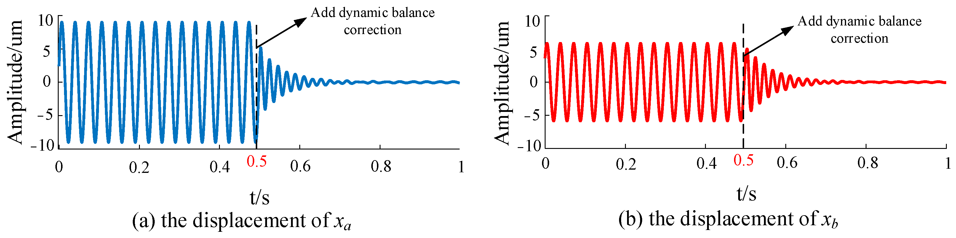
Figure 8 shows the rotor displacement of the
x direction at 1800 r/min.
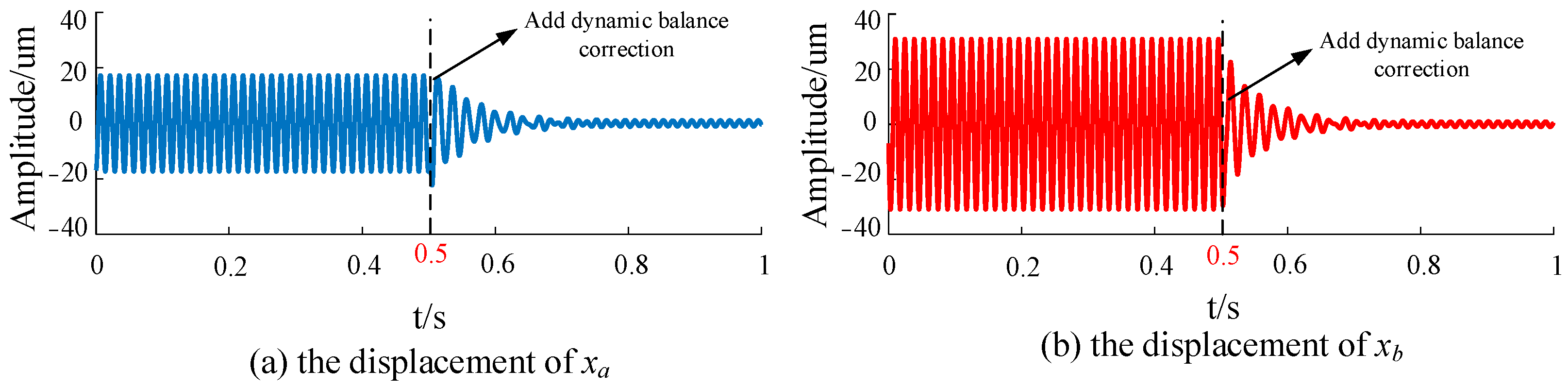
Figure 9 shows the rotor displacement of the
x direction at 4200 r/min.
As can be seen from
Figure 8 and
Figure 9, due to the existence of unbalanced mass, centrifugal force is generated when the rotor rotates, causing vibration displacement at the same frequency as the rotational speed. The vibration displacement is sinusoidal. Dynamic balance correction is applied at 0.5 s; the rotor vibration displacement decreases rapidly and the decrease ratio reaches more than 90%.
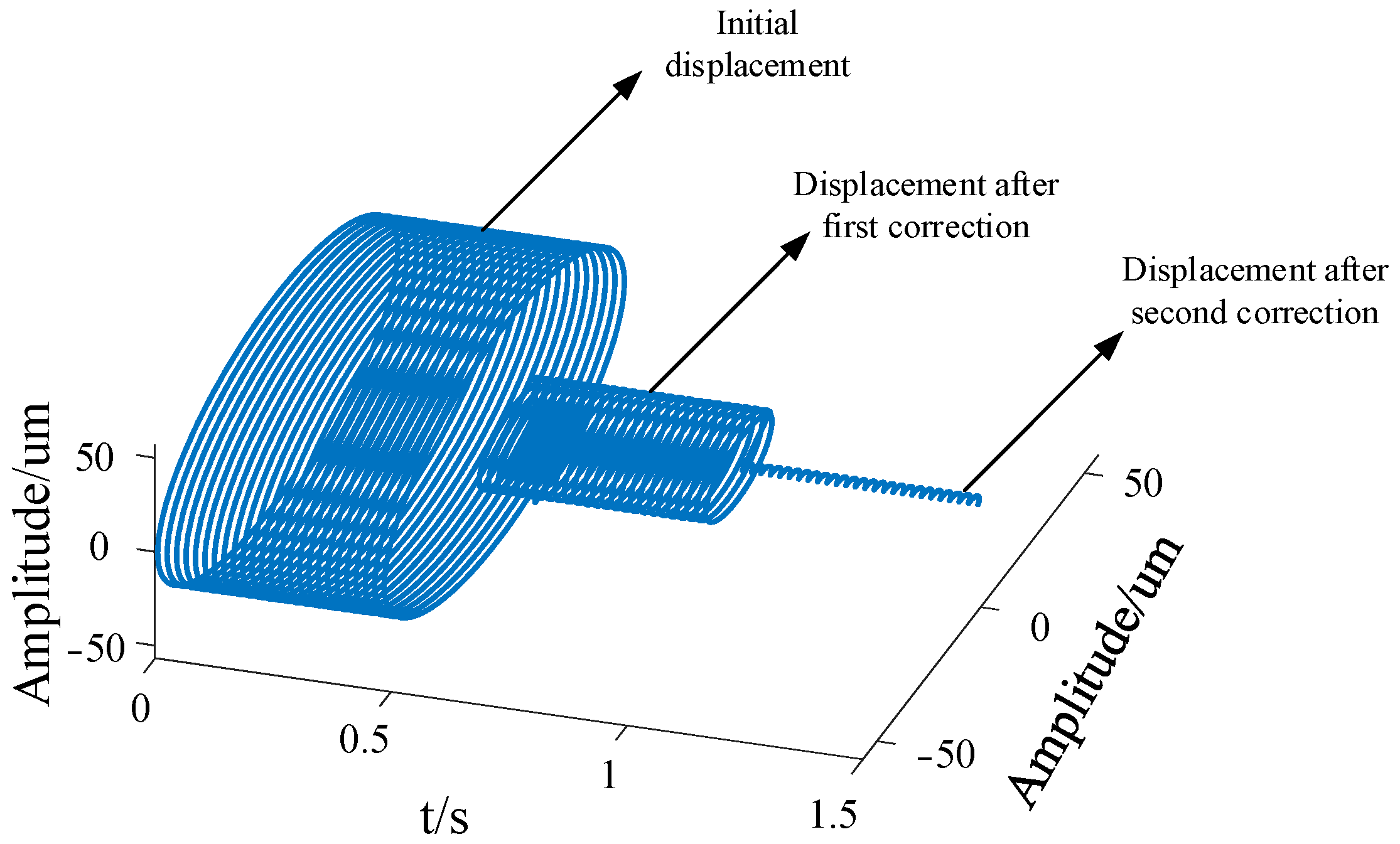
In order to fit the actual situation more accurately, the finite stud holes on the counterweight plate are simulated. Suppose that there are sixteen stud holes on the counterweight plate and the angle between the two adjacent stud holes is 22.5 degrees. The simulated counterweight mass is taken as an integer in grams.
In order to better observe the correction effect of the two dynamic balances, the axis track before the dynamic balance correction and the axis track after the two dynamic balance corrections are placed on a graph for comparison, as shown in
Figure 10.
It can be seen from the figure that the vibration displacement of the rotor decreases after a dynamic balance correction. But due to the limitations of the counterweight plate and the counterweight mass, the accuracy requirements cannot be met. After two dynamic balance corrections, the vibration displacement of the rotor is significantly reduced.
5. Experimental Research
In order to further verify the effectiveness of the proposed method for the dynamic balance correction of the AMB rotor, the dynamic balance correction experiment was carried out on the AMB rotor test rig. The test rig includes a controller, power amplifier, magnetic bearing rotor system, fiber optical sensor frequency converter and host computer, as shown in
Figure 11.
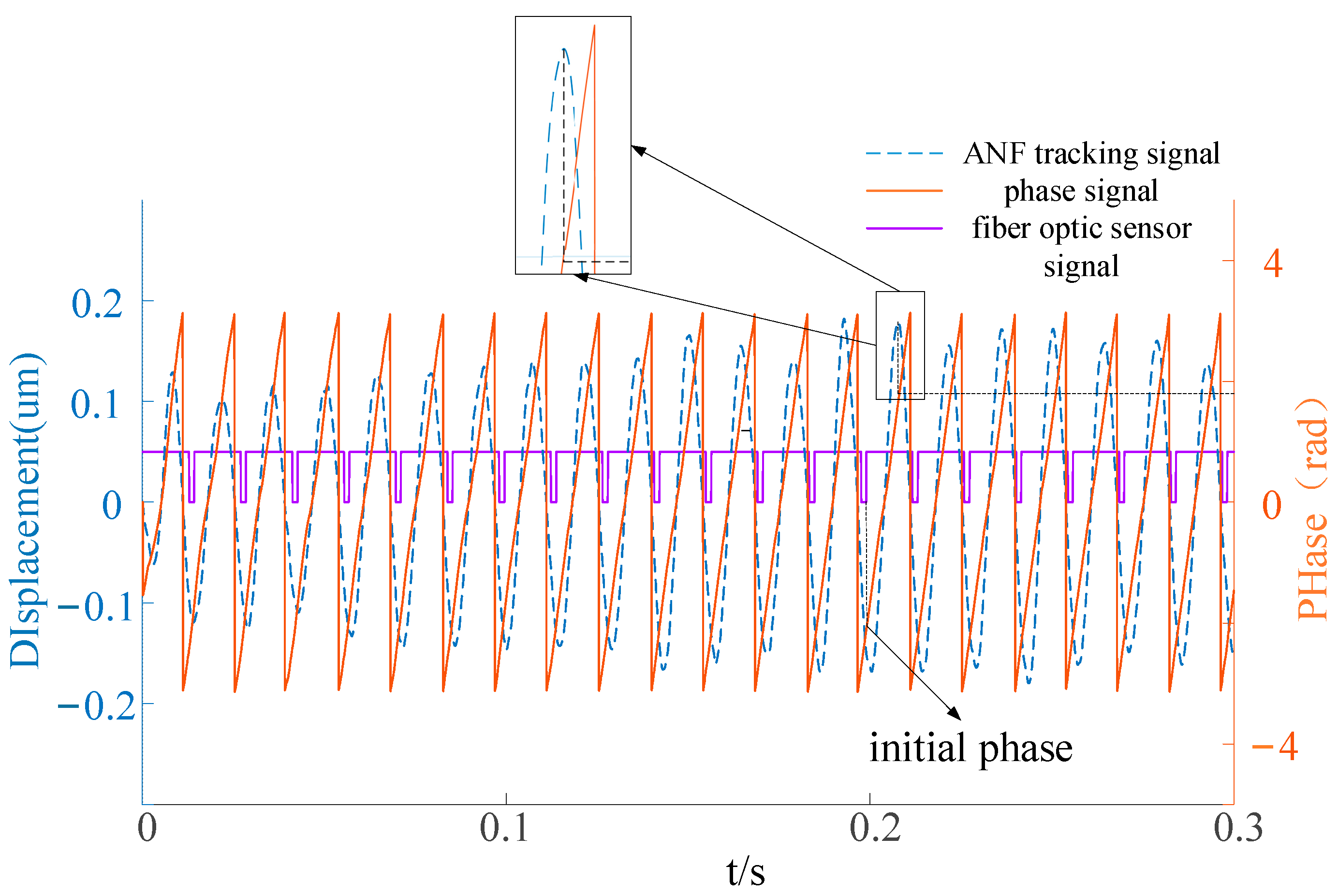
The square wave signal of the fiber optical sensor is introduced into the acquisition system. As shown in
Figure 12, the rising edge of the square wave is the zero phase of the vibration displacement vector. Since the marker is located at the center of the starting stud hole, the zero phase of the vibration displacement vector and the counterweight vector are unified.
The AMB rotor is driven to 70 Hz and the initial vibration displacement vectors
Da0 and
Db0 are calculated. The test weight mass
MA and
MB are added successively at the end
A and
B, and the specific values are shown in Equation (18). The vibration displacement vector of the two test weights is obtained.
The initial vibration displacement vector and the vibration displacement vector of the two test weights are shown in
Table 3.
According to Equations (16) and (17), the influence coefficient and final counterweight are calculated, and the dynamic balance of the rotor is corrected.
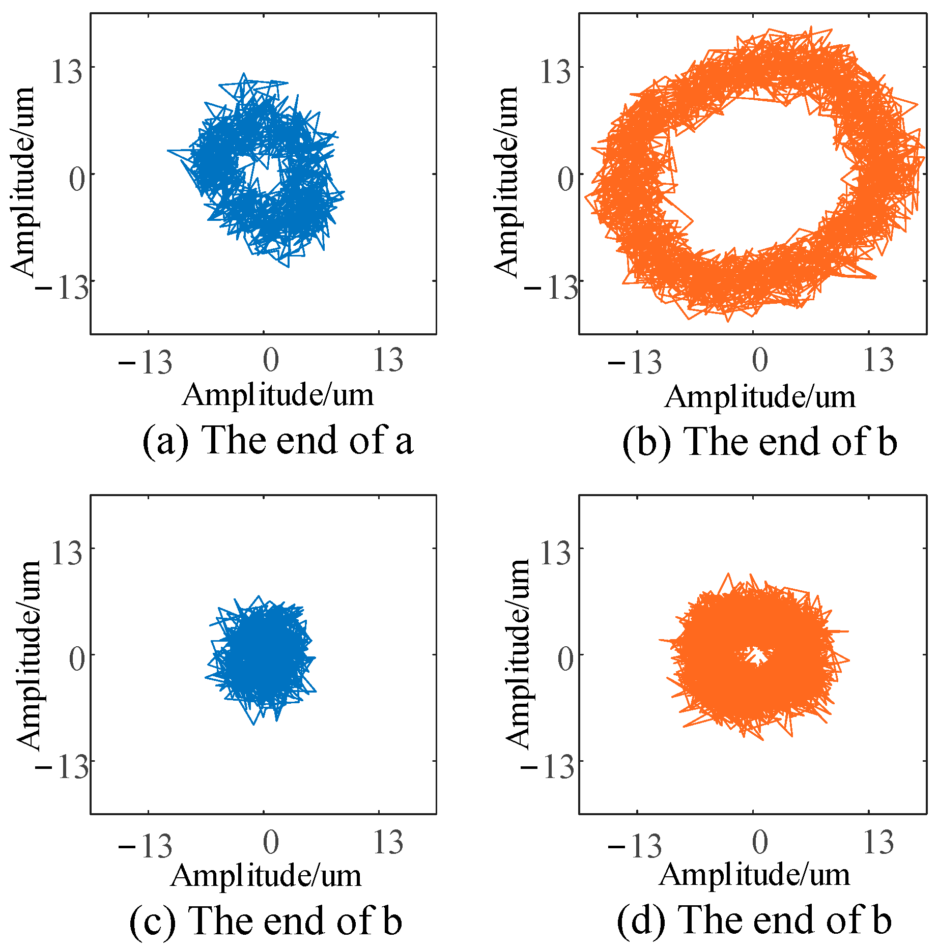
Figure 13a,b show the axis trajectories at both ends
A and
B before dynamic balance, respectively.
Figure 13c,d respectively show these axis trajectories after dynamic balance.
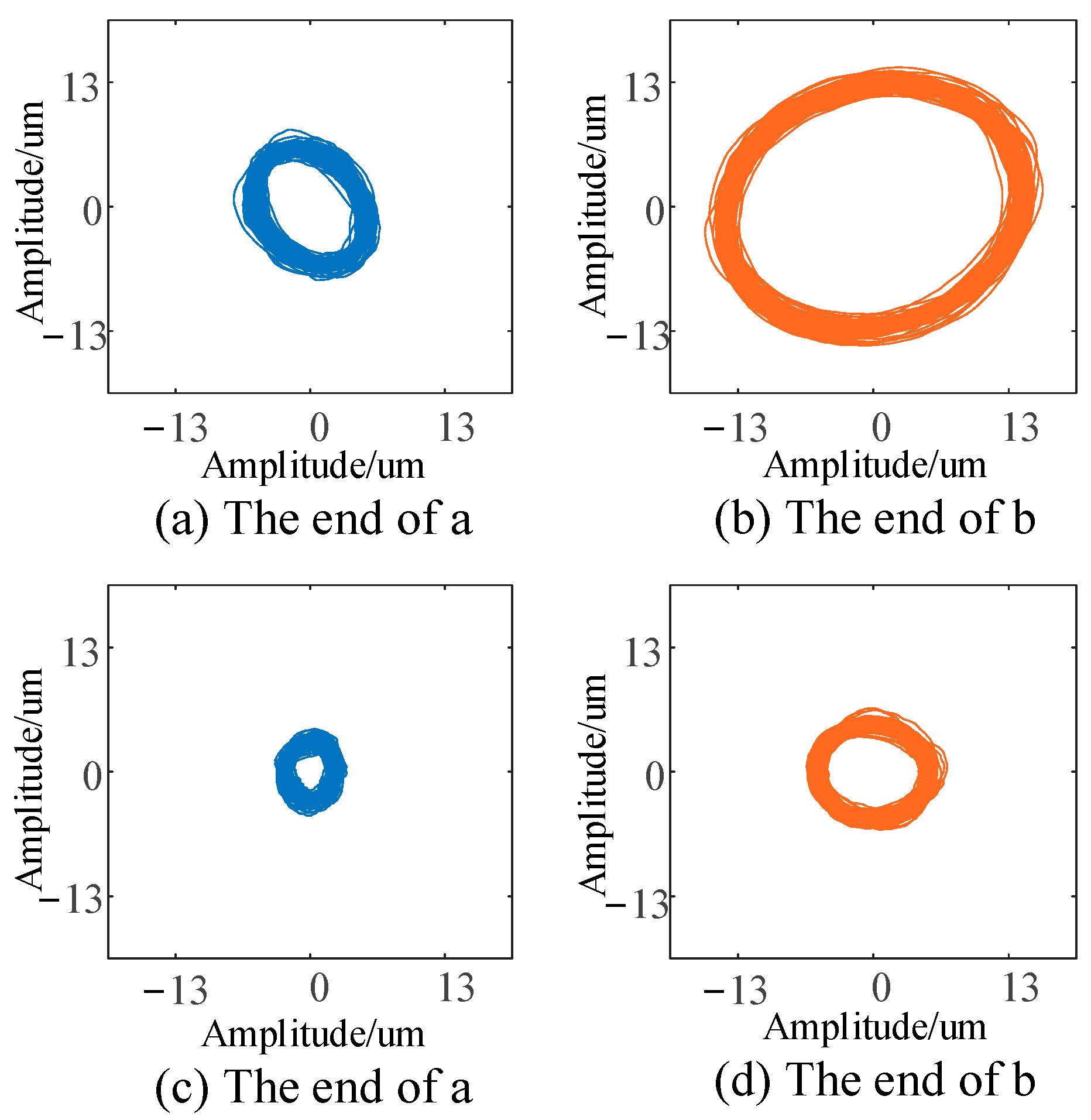
As can be seen from the figure, the collected signal contains not only the displacement signal at the rotational speed frequency, but also the disturbance signal generated by the hardware system. In order to make it easier to observe, the displacement signal obtained by ANF tracking is used to draw the axis trajectory which only includes the displacement signal at the rotational speed frequency; this is shown in
Figure 14.
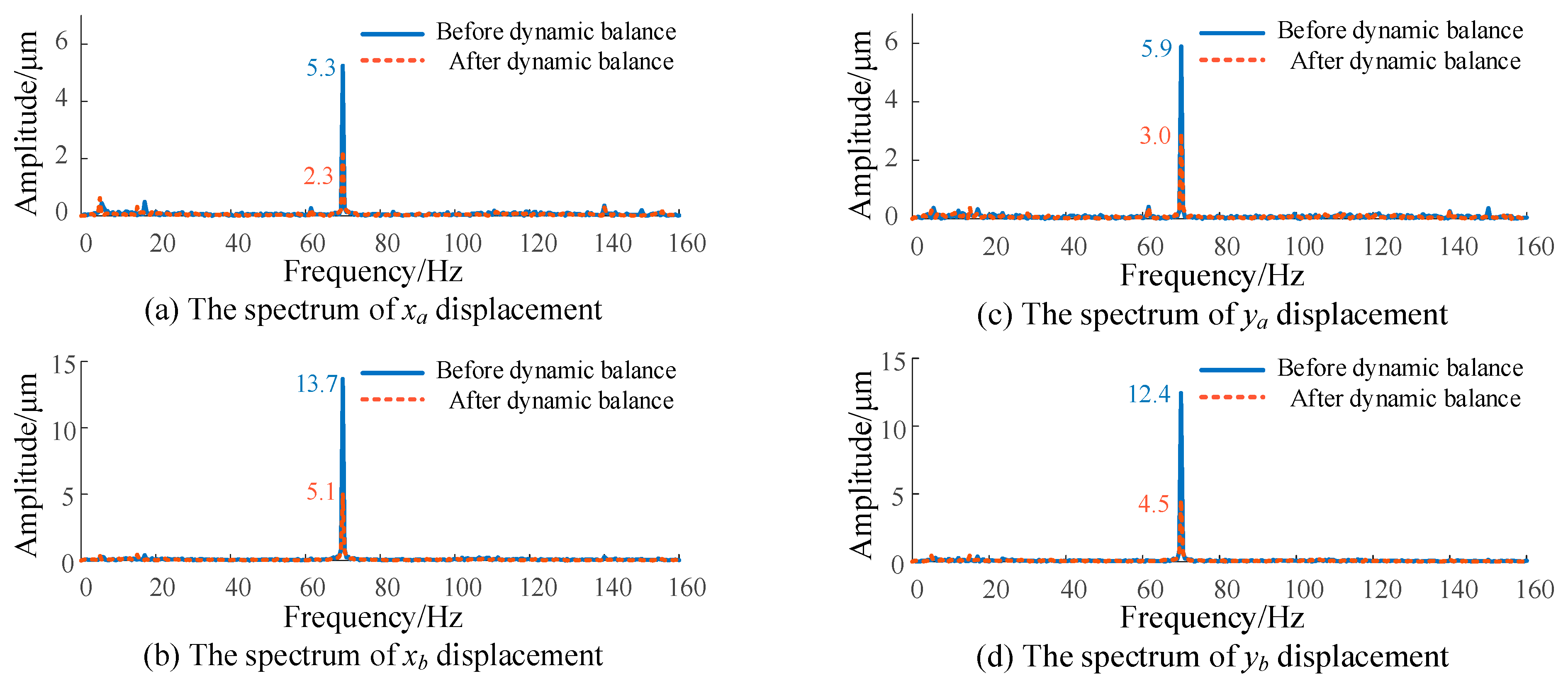
Figure 15 shows the displacement spectrum of each end of the rotor before and after dynamic balance. It can be seen from the figure that at the speed of 4200 r/min, the displacement amplitudes of the
xa,
xb,
ya and
yb ends of the rotor decreased by 56.6%, 62.8%, 49.2% and 63.7%, respectively, after dynamic balance.
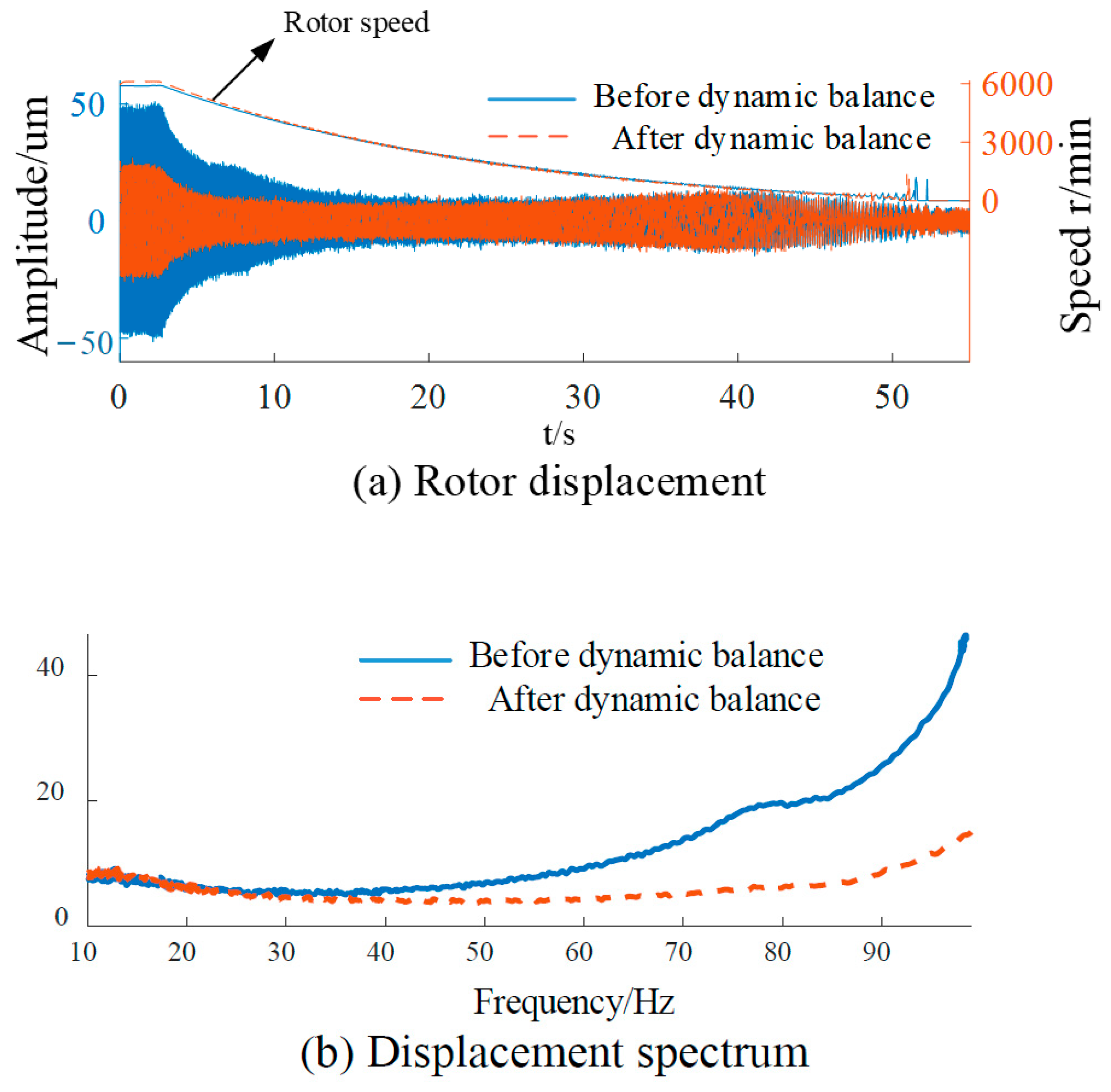
We can drive the rotor to 100 Hz and then decelerate freely.
Figure 16a is a comparison diagram of the displacement before and after dynamic balance with the decrease in rotational speed.
Figure 16b is a spectrum analysis diagram. It can be observed from the figure that the vibration amplitude of the rotor decreases at different rotational speeds, and the higher the rotational speed is, the more significant the decrease in the displacement amplitude will be.
6. Conclusions
Aiming at the mass imbalance problem of AMB rotor, a dynamic balance correction method based on ANF and ICM is proposed in this paper. Firstly, the improved ANF algorithm is used to track the displacement signal of the AMB rotor, and the amplitude and phase of the displacement signal are calculated. Then, the ICM is used to solve the counterweight mass of the rotor dynamic balance, and the dynamic balance of the rotor is corrected. Finally, the feasibility of the method is verified by simulation and experiment. The following conclusions can be drawn.
- (1)
The improved ANF algorithm adds an adaptive module to the input signal, which can modify the parameters according to the amplitude and frequency of the signal so as to realize the accurate tracking of the displacement signal and calculate the amplitude and phase information. Therefore, the displacement signal of the rotor can be transformed into the displacement vector used in the ICM.
- (2)
With the help of ANF algorithm and fiber optical sensor, the linear relationship between the rotor counterweight mass and rotor displacement response is calculated by ICM, and the counterweight mass of rotor balance is solved. The dynamic balance correction of the rotor can be effectively realized by a double-sided counterweight.
- (3)
The dynamic balance correction method of the AMB rotor based on ANF and ICM proposed in this paper can reduce the displacement unbalance of the rotor ends of the test rig used in this paper by 56.6%, 62.8%, 49.2% and 63.7%, respectively. The dynamic balance effect can be further improved after improving the counterweight phase accuracy and counterweight quality accuracy.
The dynamic balancing method presented in this paper can also be applied to rotating components supported by conventional bearings. The on-site dynamic balancing of rotating components can be achieved by deploying displacement sensors.
Finally, although the method in this paper can greatly reduce the imbalance caused by the rotor mass eccentricity, there are still some shortcomings. Due to the need to repeatedly test weights and adjust counterweights, the machine’s start–stop problem cannot be avoided; a phase detector is required to mark the initial phase. Aiming at the above problems, the next step is to study the virtual test weight of the rotor. In addition, an algorithm should be found in order to identify the phase of the rotor, replacing the hardware with software.


