Article

Tooth Movement Patterns Based on Traction Methods for Mandibular Canine Retraction Using Skeletal Anchorage: A Finite Element Analysis

1
Department of Orthodontics, School of Dentistry, Wonkwang University, Iksan 54538, Republic of Korea
2
Wonkwang Dental Research Institute, Wonkwang University, Iksan 54538, Republic of Korea
3
Institute of Biomaterials and Implant, Wonkwang University, Iksan 54538, Republic of Korea
4
Postgraduate Orthodontic Program, Arizona School of Dentistry & Oral Health, A.T. Still University, Mesa, AZ 85206, USA
5
School of Dentistry, Kyung Hee University, Seoul 02447, Republic of Korea
*
Author to whom correspondence should be addressed.
These authors contributed equally to this work.
Appl. Sci. 2025, 15(8), 4109; https://doi.org/10.3390/app15084109
Submission received: 13 March 2025 / Revised: 2 April 2025 / Accepted: 4 April 2025 / Published: 8 April 2025
(This article belongs to the Special Issue Trends and Prospects of Orthodontic Treatment)

Abstract

:
Objective: This study compared the tooth movement patterns of a power arm and a lever jig during mandibular canine retraction into a premolar extraction space using skeletal anchorage. Methods: A finite element model was developed based on anatomical structures. A mini-implant was placed between the mandibular second premolar and first molar, and canine retraction was simulated using a power arm and a lever jig. The lever jig’s vertical arm lengths were 6 mm, 8 mm, and 10 mm, corresponding to force application distances of 4.5 mm, 6.4 mm, and 8.2 mm from the archwire, matching the power arm. Finite element analysis was performed using linear mechanical properties and an explicit method. Results: With the power arm, increasing vertical length led to greater extrusion, while the posterior force remained unchanged. The lever jig also showed increased extrusion with length but to a lesser extent. Posterior force increased proportionally with the lever jig length. Initial displacement analysis showed greater extrusion and distal tipping with the power arm, while the lever jig suppressed extrusion and facilitated controlled tipping. Stress analysis revealed a more uniform periodontal ligament stress distribution with the lever jig. Conclusion: The lever jig minimizes extrusion and enhances force concentration posteriorly, promoting efficient distal movement.

1. Introduction

In premolar extraction cases, the posterior retraction of the canine is essential for securing adequate space to establish proper occlusion and align the anterior teeth. However, due to the relatively long root of the canine, its center of resistance is positioned more apically compared to other teeth [1]. Consequently, improper application of retraction forces can result in excessive distal tipping rather than controlled bodily movement. This undesirable inclination may induce vertical bowing effects, potentially compromising occlusal stability and overall treatment outcomes [2,3].
To mitigate vertical bowing, a commonly employed approach involves attaching a power arm to the archwire to shift the point of force application apically while utilizing archwires with sufficient rigidity [4,5,6]. However, even with this method, complete prevention of vertical bowing remains challenging.
Recently, a new device called the lever jig has been introduced, utilizing the principle of a first-class lever to enhance moment generation during retraction [7]. By adjusting the length of the jig, the moment-to-force ratio can be quantitatively controlled, allowing for more precise regulation of tooth movement dynamics.
Finite Element Analysis (FEA) is a widely used computational tool in dentistry for evaluating the biomechanical behavior of dental materials, implants, prostheses, and craniofacial structures under various loading conditions. Its non-invasive nature enables effective treatment planning and enhances the design of dental restorations and devices. In orthodontics, FEA is extensively applied to analyze biomechanical responses related to tooth movement [8,9,10,11,12,13,14,15,16]. Previous studies have explored various strategies to control vertical bowing during canine retraction, including the use of power arms and rigid archwires. While these methods have demonstrated some effectiveness, they do not fully eliminate vertical bowing. The lever jig presents a promising alternative by enabling more precise control over force application, potentially improving the predictability and efficiency of canine retraction. This is because a greater moment can be expected through the interaction with the main archwire, rather than by using a power arm to approximate the force to the center of resistance of the tooth in a clinical setting.
The objective of this study is to utilize FEA to (1) compare force transmission and stress distribution among different traction methods and (2) analyze the displacement patterns of the mandibular canine under various traction conditions, thereby assessing the effectiveness of the lever jig relative to conventional retraction techniques.

2. Materials and Methods

2.1. Fabrication of the Lever Jig

Clinically, the lever jig is fabricated using 0.016 × 0.022-inch stainless steel wire and is secured onto the main archwire in a hook-like manner without additional ligation. The length of the vertical arm is adjusted based on the desired moment-to-force (M/F) ratio, with a longer vertical arm generating a higher M/F ratio (Figure 1).

2.2. Experimental Design

The experiment was designed to observe the biomechanical sliding mechanics during extraction space closure by applying force to absolute anchorage positioned above the center of resistance of the canine. For this purpose, two models were compared:
  • A model utilizing a power arm positioned between the lateral incisor and the canine on the main archwire;
  • A model incorporating a lever jig.
An orthodontic mini-implant was placed between the mandibular second premolar and the mandibular first molar, ensuring that the line of action of the applied force passed above the center of resistance of the canine. A mini-implant with a diameter of 1.6 mm and a length of 6 mm was selected for this study.
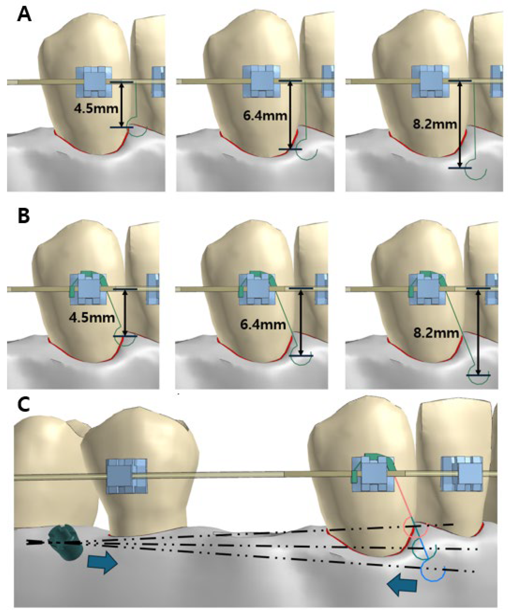
To precisely define the spatial relationships among key anatomical and mechanical reference points, the vertical positions of the mini-implant, center of resistance of the canine, and force application point were measured relative to the main archwire (Figure 2 and Figure 3).
The lever jig model’s vertical distances from the force application point to the main archwire were determined based on different vertical arm lengths (6, 8, and 10 mm) (Figure 3). These measurements were used to adjust the vertical length of the power arm to ensure a valid comparison. This setup was implemented to construct the finite element model for further biomechanical analysis.

2.3. Finite Element Analysis (FEA) Modeling

A computer-aided design (CAD) model was developed for finite element analysis using VPS Software (version 2023.0; ESI Group, Paris, France), based on a computed tomography scan of a dehydrated adult skull. The geometric information of the human skull was imported into Visual Crash for PAM (Version 17.0; ESI Group, Paris, France) to generate a tetrahedral finite element mesh.
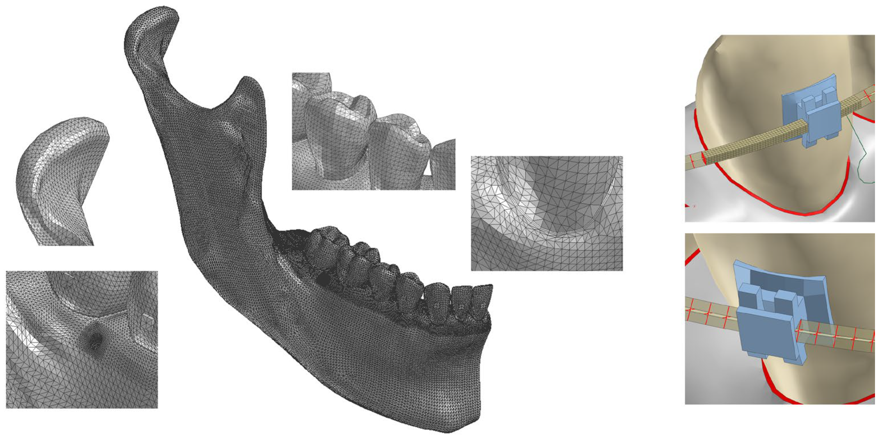
To simplify the model while maintaining accuracy, symmetry was assumed between both sides of the dental arch. Consequently, the analysis was conducted using only the lower right mandible, including the tooth, bracket, archwire, and alveolar bone. The alveolar bone was further divided into cortical and cancellous bone to represent its biomechanical properties accurately (Figure 4).
Three-dimensional models of the teeth were constructed based on computed tomography images of a dental study model, referencing a single adult. Each tooth was meshed using tetra solid (Figure 4). The archwire passing through the bracket slot of the canine was modeled using solid elements and contact conditions were applied between the solid elements and brackets, while the archwire in contact with other teeth were modeled using beam elements along the centerline of the archwire, covers using the null shell elements and connects to the beam elements using constraints and contact conditions were applied between the brackets and shell elements to simplify and enhance the numerical efficiency.
Contact conditions were applied between the hook and the archwire to simulate realistic force interactions (Figure 3). The mesial-upper part of the bracket, serving as the fulcrum point, was modeled using solid elements, with contact conditions applied between the wire and the bracket. The angle of the lever jig was fixed at 100 degrees, and the length of the vertical arm (distance from the fulcrum point at the mesial-upper part of the bracket to the center of the hook) was set at 6 mm, 8 mm, and 10 mm. The orthodontic force was applied along the line of force between the hook of the lever jig and the orthodontic mini-implant to replicate clinical loading conditions.

2.4. Material Properties

The three-dimensional finite element models of the teeth, alveolar bone, periodontal ligament (PDL), archwire, and brackets were composed of elements of varying sizes. The tetrahedral mesh size was set between 0.2 mm and 5.0 mm, ensuring computational efficiency while maintaining accuracy. Cortical and cancellous bone were assumed to be homogeneous in their material properties [17].
The PDL was modeled as a linear elastic layer with a uniform thickness of 0.2 mm [18]. Although it exhibits nonlinear viscoelastic behavior in vivo, a linear elastic assumption was adopted to simplify computation and maintain consistency with previous finite element studies [19,20,21,22] (Table 1). Similarly, the mechanical properties of the teeth, PDL, and alveolar bone were assumed to be linear elastic, homogeneous, and isotropic, based on values from prior research.
The archwire was made of 0.019 × 0.025-inch stainless steel, and the brackets were designed as 4-mm-wide edgewise brackets with a 0.022 × 0.028-inch slot [23]. A friction coefficient (μ) of 0.15 was applied between the archwire and bracket interfaces based on previously published experimental data [24].

2.5. Loading and Boundary Conditions

The geometric nonlinearity is considered with the nonlinear static implicit solution method to predict the large deformation of the hook and sliding motions of hooks and archwires accurately. And the retraction force was gradually increased to 5 N with the quasi-static assumptions. The force was applied posteriorly along the line of action between the hook and the mini-implant, ensuring consistency with clinical retraction mechanics.
Although the experiment was conducted using a finite element model of the right side of the mandible, symmetry conditions were applied to all load applications to ensure results consistent with those of the full dentition. The base of the mandible was constrained in all degrees of freedom to simulate the natural stability of the jaw while allowing physiologic displacement of the teeth.
Simulations were performed using Virtual Performance Solution software (version 2023.0; ESI Group, Paris, France), and Visual Viewer (version 2024.0; ESI Group, Paris, France) was used for data visualization and plotting.

2.6. Coordinate System

To accurately describe tooth movement, a coordinate system was established using the center of the bracket as the reference point. The axes were defined as follows:
  • Positive X-axis: Mesial direction;
  • Positive Y-axis: Lingual direction;
  • Positive Z-axis: Coronal direction.

2.7. Dynamic Simulation of Initial Tooth Movement Process

The applied load on the mandibular canine was evaluated based on:
  • The load transmitted to the bracket;
  • The displacement of the mandibular canine;
  • The distribution of tensile and compressive stress in the PDL.
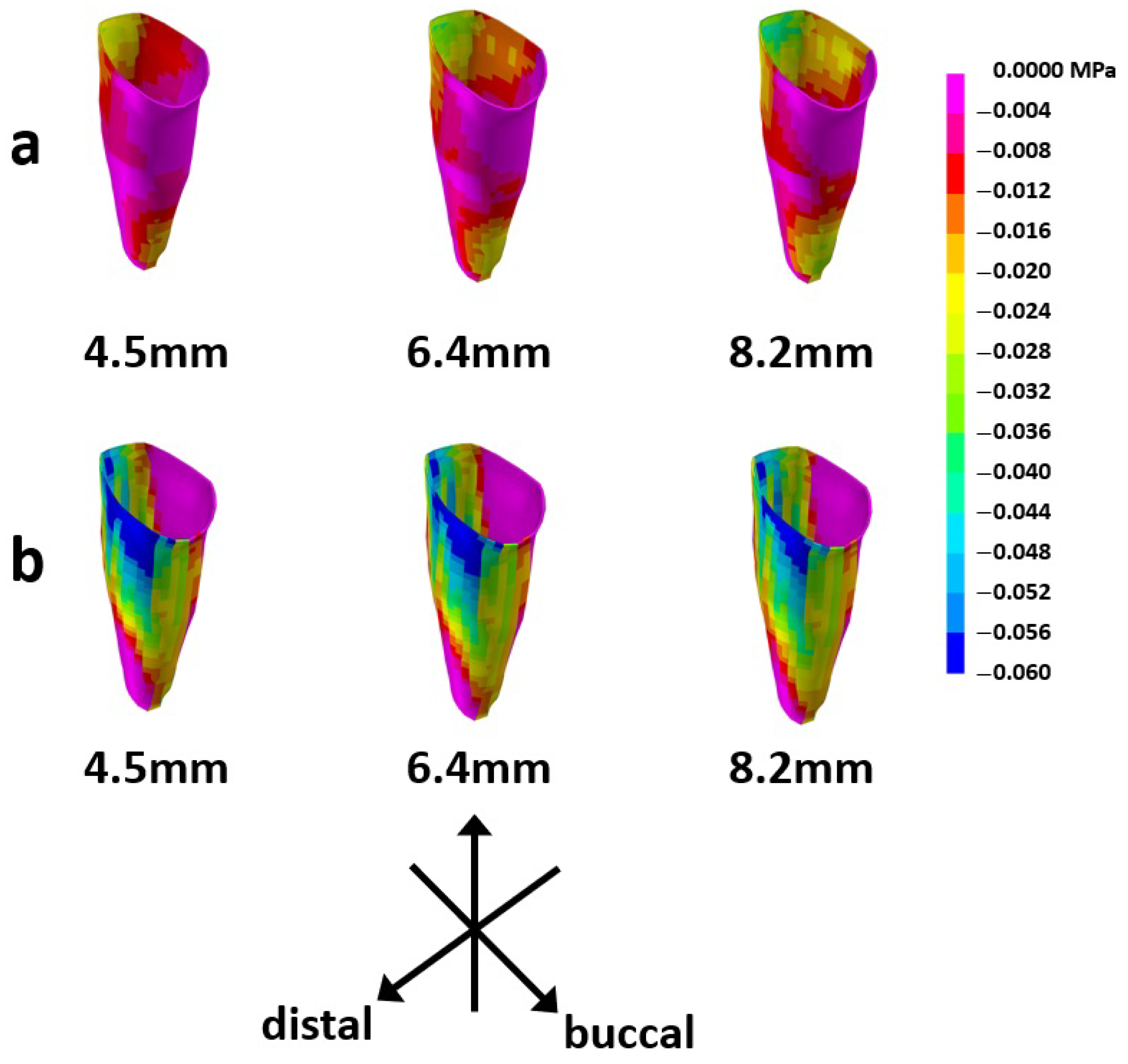
The distribution of major principal stress was set within a range of 0.000 to 0.100 MPa, while the distribution of minor principal stress was defined within a range of −0.060 to 0.000 MPa.
Based on the local coordinate system, displacement values were plotted within a range of 0 to 0.10 mm, while contour plots were generated within a range of −0.10 mm to +0.03 mm.

3. Results

3.1. Load Transmission to the Bracket

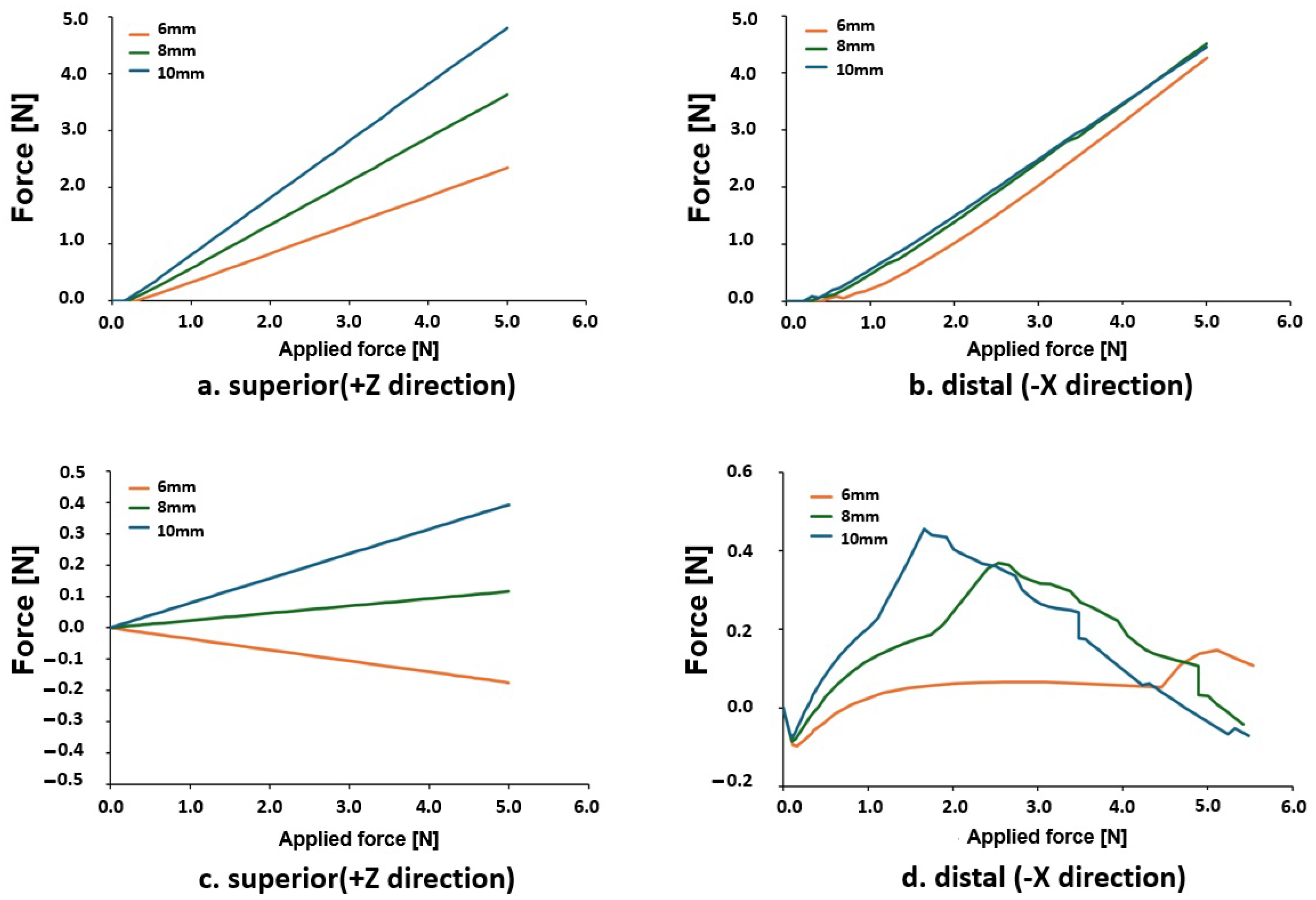
The forces transmitted to the bracket in the superior (+Z) and distal (−X) directions were analyzed for the power arm and lever jig (Figure 5).
In the power arm model (Figure 5a), increasing the length of the power arm resulted in greater force transmission in both directions, with a notable reduction in force loss in the superior direction. In the distal direction, no significant difference was observed between the 8 mm and 10 mm power arms (Figure 5b).
In the lever jig model (Figure 5c,d), the force transmission pattern differed from the power arm. Initially, the force was directed upward, but as the bracket moved, the vertical arm of the jig pressed against the bracket, redirecting the force downward and backward. This sequential force shift resulted in more stable force transmission, reducing overall load variations on the bracket.

3.2. Initial Displacement Pattern of the Canine

The initial displacement pattern of the mandibular canine was analyzed using contour plots (Figure 6). In the power arm model (Figure 6a), increasing power arm length resulted in greater extrusion (+Z direction) and distal tipping (−X direction) of the crown. The displacement difference between the crown and root apex increased as power arm length increased.
In the lever jig model (Figure 6b), increasing the jig length led to a reduction in distal tipping of the crown. The displacement difference between the crown and root was smaller compared to the power arm.

3.3. Tensile Stress Distribution in the PDL

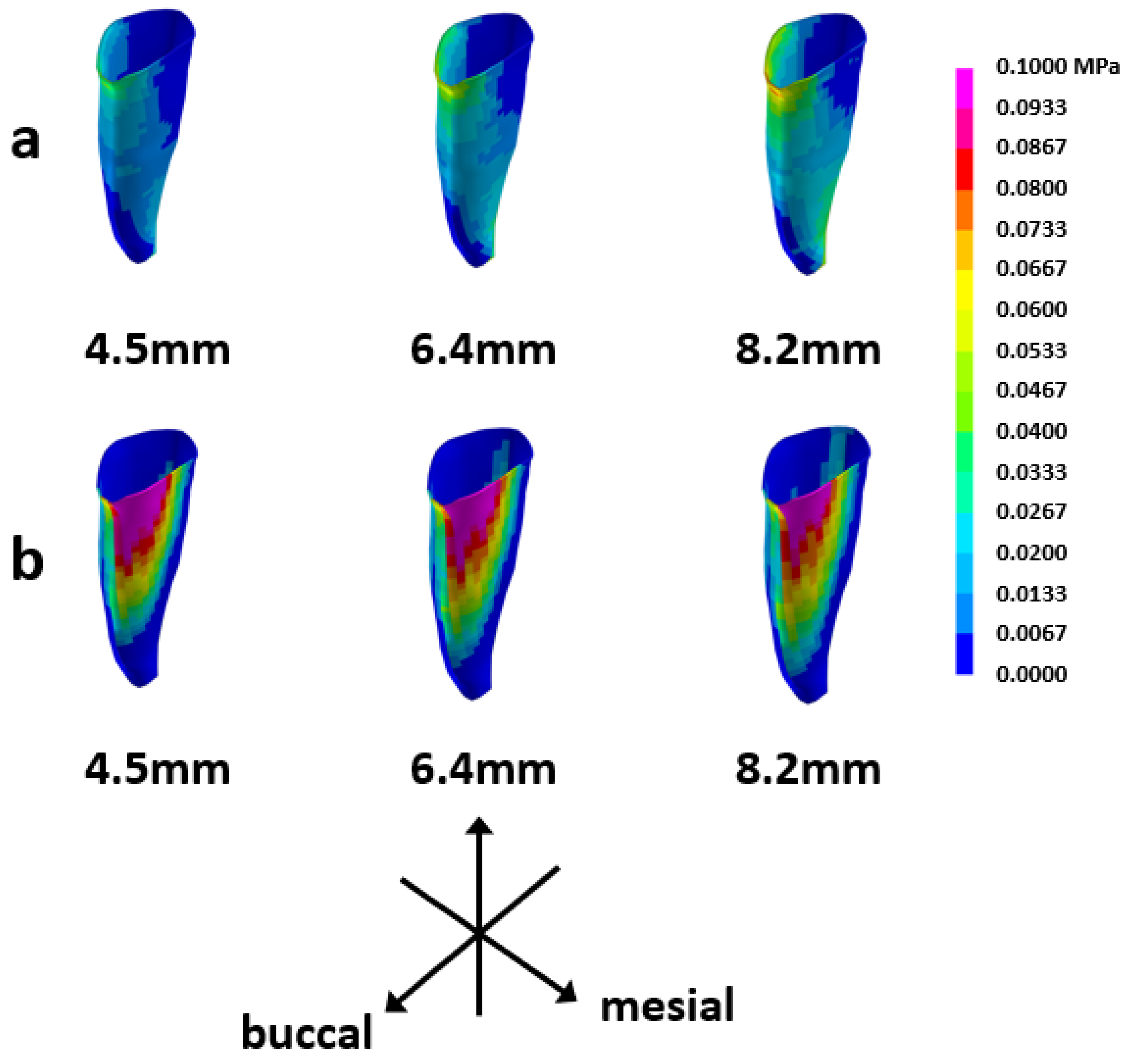
The distribution of tensile stress in the PDL was analyzed for different traction methods (Figure 7). In the power arm model (Figure 7a), tensile stress was concentrated in the cervico-buccal and apico-lingual regions, with stress intensity increasing as the power arm length increased.
Increasing jig length in the lever jig model (Figure 7b) resulted in greater stress distribution in the apical region, extending further downward. Additionally, tensile stress in the mesio-buccal area increased, with a minor expansion of the lingual stress distribution.

3.4. Compressive Stress Distribution in the PDL

The distribution of compressive stress in the PDL was analyzed for different traction methods (Figure 8). In the power arm model (Figure 8a), increasing power arm length led to greater compressive stress in the cervico-lingual and apico-buccal regions, with a notably higher concentration of compressive stress in the cervical area.
In the lever jig model (Figure 8b), increasing jig length resulted in compressive stress shifting toward the apical region on the distal surface, while stress in the cervico-distal region decreased. Compared to the power arm, the lever jig exhibited lower compressive stress in the cervico-distal area at the same extension lengths.

4. Discussion

This study analyzed the biomechanical differences between power arms and lever jigs for mandibular canine retraction using FEA. While the power arm facilitates en-masse retraction of the anterior segment, the lever jig is designed for isolated canine retraction. Nevertheless, comparing the lever jig with the commonly used power arm provides insight into their biomechanical differences.
Recent studies have demonstrated that increasing the length of the power arm to approximate the center of resistance of the tooth can reduce the tendency for distal tipping [11]. However, this approach was insufficient in preventing extrusion. In contrast, the application of a lever jig has been shown to effectively control both distal tipping and extrusion. These results indicate that the lever jig provides a more controlled force application, improved bodily movement, and a more balanced stress distribution compared to the power arm. Notably, the lever jig effectively suppressed extrusion despite a similar posterior-superior force vector, suggesting its potential advantages in controlling vertical displacement. This observation can be made from Figure 5d. The irregular pattern of the graph can be attributed to the fact that the lever jig is not directly affixed to either the bracket or the archwire, resulting in interactions with the main archwire or the bracket. Specifically, the hook, which is wrapped around the posterior of the canine bracket, makes contact with the main archwire, generating a hook contact force. This interaction leads to the irregular redistribution of force, as evidenced in the graph.
A key biomechanical difference was how force was transmitted to the bracket and tooth. Increasing power arm length shifted the force vector posterior-superiorly, leading to extrusion and distal tipping, consistent with previous studies [2,3,4,5]. However, this effect plateaued beyond 8–10 mm, reducing efficiency. In contrast, the lever jig redirected force downward and backward by pressing against the bracket, minimizing extrusion and promoting bodily movement. This mechanism highlights its potential for torque and root control during space closure.
Stress distribution analysis further supported these findings. The power arm concentrated tensile and compressive stress in localized PDL regions, increasing the risk of undesirable rotation. Conversely, the lever jig maintained a broader, evenly distributed stress pattern, particularly in the apical and mesio-buccal areas, potentially reducing unwanted side effects like root resorption.
Despite its strengths, this study has limitations. The PDL was modeled as a linear elastic material, though in reality, it exhibits nonlinear and viscoelastic properties. Additionally, only initial displacement was analyzed, limiting insights into progressive tooth movement. Future studies should incorporate nonlinear modeling and longitudinal assessments to validate these findings in vivo. A further limitation is that the model was derived from the CBCT data of a single individual, and thus the initial tooth alignment may not have been ideal for precise bracket and archwire placement. To reduce potential discrepancies, bracket heights were uniformly standardized, and controlled movement of the main archwire was allowed under consistent conditions.
Clinically, the lever jig may offer advantages in reducing tipping and extrusion while improving root control, making it a valuable tool for orthodontic space closure. Further clinical studies are necessary to confirm its long-term effects on root resorption, periodontal health, and progressive tooth movement under continuous force application.

5. Conclusions

Based on this study, the lever jig may offer several advantages over the power arm in clinical orthodontics.
  • It redirects force more efficiently, reducing unnecessary vertical displacement.
  • It minimizes tipping and maintains a better moment-to-force ratio for controlled translation.
  • It generates a more balanced stress field in the PDL, reducing excessive concentration in limited areas.
  • Since the lever jig naturally minimizes tipping and extrusion, additional mechanics, such as torquing auxiliaries, may be less necessary.
These benefits suggest that the lever jig can be a valuable tool for orthodontic space closure and anchorage control, particularly in cases requiring precise root control.

Author Contributions

Conceptualization, D.-H.L., J.-M.C. and S.-K.C.; methodology, D.-H.L. and J.-M.C.; validation, J.H.P., N.-Y.C. and K.-H.K.; formal analysis, D.-H.L. and J.-M.C.; investigation, S.-K.C.; resources, K.-H.K.; data curation, N.-Y.C.; writing—original draft preparation, D.-H.L. and S.-K.C.; writing—review and editing, J.H.P., N.-Y.C. and K.-H.K.; supervision, S.-K.C.; project administration, S.-K.C. All authors have read and agreed to the published version of the manuscript.

Funding

This research received no external funding.

Institutional Review Board Statement

Not applicable.

Informed Consent Statement

Not applicable.

Data Availability Statement

The authors declare that the materials are available.

Acknowledgments

This paper was supported by Wonkwang University in 2024.

Conflicts of Interest

The authors declare no conflict of interest.

References

  1. Kuruthukulam, R.M.; Patil, A.S. The center of resistance of a tooth: A review of the literature. Biophys. Rev. 2023, 15, 35–41. [Google Scholar] [CrossRef] [PubMed]
  2. Kawamura, J.; Park, J.H.; Kojima, Y.; Tamaya, N.; Kook, Y.A.; Kyung, H.M.; Chae, J.M. Biomechanical analysis for total distalization of the maxillary dentition: A finite element study. Am. J. Orthod. Dentofac. Orthop. 2021, 160, 259–265. [Google Scholar] [CrossRef] [PubMed]
  3. Chae, J.M.; Park, J.H.; Kojima, Y.; Tai, K.; Kook, Y.A.; Kyung, H.M. Biomechanical analysis for total distalization of the mandibular dentition: A finite element study. Am. J. Orthod. Dentofac. Orthop. 2019, 155, 388–397. [Google Scholar] [CrossRef] [PubMed]
  4. Sung, E.H.; Kim, S.J.; Chun, Y.S.; Park, Y.C.; Yu, H.S.; Lee, K.J. Distalization pattern of whole maxillary dentition according to force application points. Korean J. Orthod. 2015, 45, 20–28. [Google Scholar] [CrossRef]
  5. He, X.; Zhuang, W.-H.; Zhang, D.-L. A three-dimensional finite element analysis: Maxillary dentition distalization with the aid of microimplant in lingual orthodontics. Int. J. Gen. Med. 2021, 14, 8455–8461. [Google Scholar] [CrossRef]
  6. Lee, J.Y.; Park, J.H.; Lee, N.K.; Kim, J.; Chae, J.M.; Kook, Y.A. Biomechanical analysis for total arch distalization according to location of force application and types of temporary skeletal anchorage devices. Clin. J. Korean Assoc. Orthod. 2021, 11, 89–101. [Google Scholar] [CrossRef]
  7. Goh, M.S.; Choi, S.K. Orthodontic Treatment of a Stage IV Periodontitis Patient Exhibiting Severe Attachment Loss and Pathological Tooth Migration. Clin. J. Korean Assoc. Orthod. 2024, 14, 227–236. [Google Scholar] [CrossRef]
  8. Chen, J.; Zhu, D.; Zhao, M.; Cheng, Z.; Pan, Y.; Liu, X. Three-dimensional finite element analysis of the optimal mechanical design for maximum inward movement of the anterior teeth with clear aligners. Sci. Rep. 2024, 14, 13203. [Google Scholar] [CrossRef]
  9. Guo, R.; Li, L.; Lam, X.Y.; Qin, Q.; Zheng, Y.; Huang, Y.; Lin, Y.; Li, W. Tooth movement analysis of maxillary dentition distalization using clear aligners with buccal and palatal mini-screw anchorages: A finite element study. Orthod. Craniofac. Res. 2024, 27, 868–876. [Google Scholar] [CrossRef]
  10. Wu, J.L.; Liu, Y.F.; Peng, W.; Dong, H.Y.; Zhang, J.X. A biomechanical case study on the optimal orthodontic force on the maxillary canine tooth based on finite element analysis. J. Zhejiang Univ. Sci. B 2018, 19, 535. [Google Scholar] [CrossRef]
  11. Zhao, W.; Lou, Y.; Yan, W. Evaluation of stress and displacement of maxillary canine during the single canine retraction in the maxillary first premolar extraction cases-A finite element study. Clin. Oral Investig. 2024, 28, 206. [Google Scholar] [CrossRef] [PubMed]
  12. Schwertner, A.; de Almeida-Pedrin, R.R.; Poleti, T.M.F.F.; Oltramari, P.; de Castro Conti, A.C.F.; Cotrim-Ferreira, F.A.; de Almeida, M.R. Biomechanical analysis of total arch maxillary distalization using infrazygomatic crest miniscrews: A finite element analysis study. Prog. Orthod. 2024, 25, 10. [Google Scholar] [CrossRef] [PubMed]
  13. Kojima, Y.; Fukui, H. Numerical simulation of canine retraction by sliding mechanics. Am. J. Orthod. Dentofac. Orthop. 2005, 127, 542–551. [Google Scholar] [CrossRef] [PubMed]
  14. Jain, A.; Prasantha, G.S.; Mathew, S.; Sabrish, S. Analysis of stress in periodontium associated with orthodontic tooth movement: A three-dimensional finite element analysis. Comput. Methods Biomech. Biomed. Eng. 2021, 24, 1841–1853. [Google Scholar] [CrossRef]
  15. Atif, M.; Tewari, N.; Reshikesh, M.; Chanda, A.; Mathur, V.P.; Morankar, R. Methods and applications of finite element analysis in dental trauma research: A scoping review. Dent. Traumatol. 2024, 40, 366–388. [Google Scholar] [CrossRef]
  16. Hsu, M.L.; Chang, C.L. Application of finite element analysis in dentistry. Finite Elem. Anal. 2010, 5, 43–46. [Google Scholar]
  17. Cattaneo, P.M.; Dalstra, M.; Melsen, B. Strains in periodontal ligament and alveolar bone associated with orthodontic tooth movement analyzed by finite element. Orthod. Craniofac. Res. 2009, 12, 120–128. [Google Scholar] [CrossRef]
  18. Moga, R.-A.; Olteanu, C.D.; Delean, A.G. The importance of boundary conditions and failure criterion in finite element analysis accuracy—A comparative assessment of periodontal ligament biomechanical behavior. Appl. Sci. 2024, 14, 3370. [Google Scholar] [CrossRef]
  19. McGuinness, N.J.; Wilson, A.N.; Jones, M.L.; Middleton, J. A stress analysis of the periodontal ligament under various orthodontic loadings. Eur. J. Orthod. 1991, 13, 231–242. [Google Scholar] [CrossRef]
  20. Cobo, J.; Sicilia, A.; Argüelles, J.; Suárez, D.; Vijande, M. Initial stress induced in periodontal tissue with diverse degrees of bone loss by an orthodontic force: Tridimensional analysis by means of the finite element method. Am. J. Orthod. Dentofac. Orthop. 1993, 104, 448–454. [Google Scholar] [CrossRef]
  21. Provatidis, C.G. A comparative FEM-study of tooth mobility using isotropic and anisotropic models of the periodontal ligament. Med. Eng. Phys. 2000, 22, 359–370. [Google Scholar] [CrossRef] [PubMed]
  22. Provatidis, C.; Kanarachos, A. Boundary-type hydrodynamic analysis of tooth movement. Eng. Anal. Bound. Elem. 2000, 24, 661–669. [Google Scholar] [CrossRef]
  23. Papageorgiou, S.N.; Konstantinidis, I.; Papadopoulou, K.; Jäger, A.; Bourauel, C. Clinical effects of pre-adjusted edgewise orthodontic brackets: A systematic review and meta-analysis. Eur. J. Orthod. 2014, 36, 350–363. [Google Scholar] [CrossRef] [PubMed]
  24. Kapur Wadhwa, R.; Kwon, H.K.; Close, J.M. Frictional resistances of different bracket-wire combinations. Aust. Orthod. J. 2004, 20, 25–30. [Google Scholar] [PubMed]
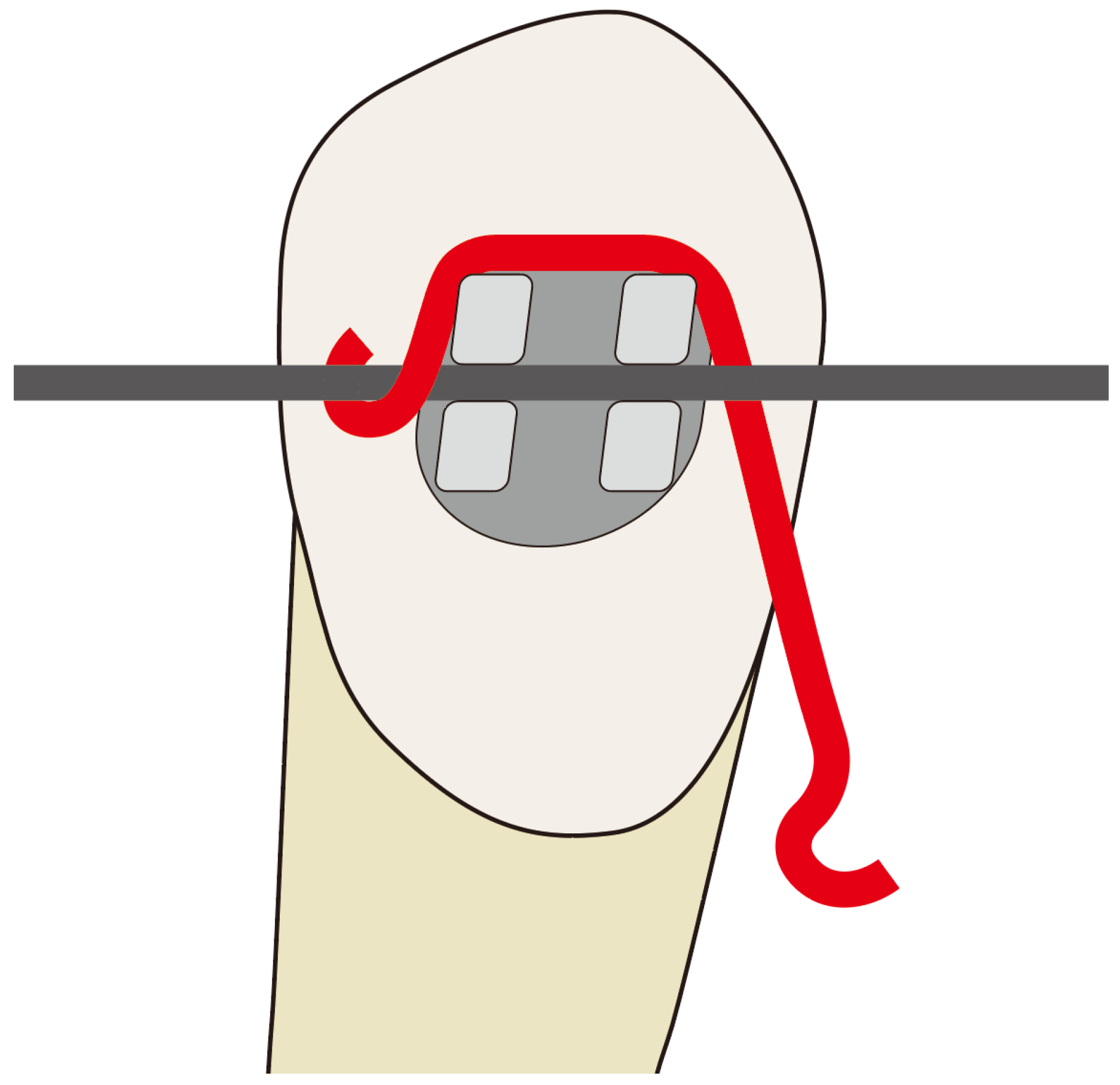
Figure 1. Configuration of a lever jig. The lever jig is fabricated using 0.016 × 0.022-inch stainless steel wire, which is designed to be inserted between the main archwire and the tooth while maintaining sufficient rigidity to withstand orthodontic forces without excessive deformation. The horizontal arm is designed to be as short as possible, while the vertical arm length is adjusted between 6–10 mm, depending on the required M/F ratio. The angle between the horizontal and vertical arms is set at 100° to ensure that the fulcrum remains stable during force application.
Applsci 15 04109 g001
Figure 2. Mandibular first premolar extraction space closure model. An orthodontic mini-implant (1.6 mm in diameter and 6 mm in length) was placed between the second premolar and first molar. The vertical distances measured were as follows: 11.1 mm from the cusp tip of the posterior teeth to the mini-implant, 6.37 mm from the archwire to the mini-implant, and 13.6 mm from the archwire to the center of resistance of the canine. The mandibular canine in the model has a length of 33.3 mm, with the center of resistance located approximately 12.9 mm above the apex.
Applsci 15 04109 g002
Figure 3. Vertical positioning of the power arm and lever jig with corresponding force vectors. (A) Configuration of the power arm with vertical lengths of 4.5 mm, 6.4 mm, and 8.2 mm. (B) Configuration of the lever jig, with vertical distance of 4.5 mm, 6.4 mm, and 8.2 mm, corresponding to vertical arm lengths of 6 mm, 8 mm, and 10 mm, respectively. (C) Schematic representation of the force vectors generated by the power arm and lever jig.
Applsci 15 04109 g003
Figure 4. Finite element analysis (FEA) model construction. Three-dimensional finite element model of the mandibular dentition and alveolar bone. The model includes the mandibular right canine, premolars, molars, brackets, archwire, and orthodontic mini-implant.
Applsci 15 04109 g004
Figure 5. Load transmitted to the bracket in the superior direction (+Z direction) and distal direction (−X direction) when using a power arm (a,b) and a lever jig (c,d).
Applsci 15 04109 g005
Figure 6. Contour plot of initial canine displacement when using a power arm (a) and a lever jig (b).
Applsci 15 04109 g006
Figure 7. Tensile stress in the PDL when using a power arm (a) and a lever jig (b).
Applsci 15 04109 g007
Figure 8. Compressive stress in the PDL when using a power arm (a) and a lever jig (b).
Applsci 15 04109 g008
Table 1. Mechanical properties of the mechanical variables.
ComponentYoung’s ModulusPoisson’s Ratio
PDL18 Mpa0.45
Cortical bone14 Gpa0.30
Trabecular bone
Stainless steel wire
1.4 Gpa
200 Gpa
0.30
0.30
Disclaimer/Publisher’s Note: The statements, opinions and data contained in all publications are solely those of the individual author(s) and contributor(s) and not of MDPI and/or the editor(s). MDPI and/or the editor(s) disclaim responsibility for any injury to people or property resulting from any ideas, methods, instructions or products referred to in the content.