1. Introduction
The rapid advance in the research and use of unmanned vehicles (UVs) is undeniable. They are used in military and civil applications, and everything indicates that they will have greater use in the future. UVs have different names according to their operating environment. Using the definitions in [
1], four types are defined depending on the medium in which they are mobilized: UAV (unmanned aerial vehicle), UGV (unmanned ground vehicle), UMV (unmanned maritime vehicle), and unmanned space systems. The latter does not have a defined acronym and corresponds to unmanned vehicles created for space applications.
UMVs can be divided into two types: if they are surface vehicles (mostly boats or small ships), they are known as unmanned surface vehicles (USVs). If they are submerged, they are called unmanned underwater vehicles (UUVs). The Mars Rovers [
2] are the most popular UGVs known to the public. In the specific case of rovers, they usually have a predefined route for data collection and, in some cases, soil samples or materials that they can collect along the way. Data are usually sent directly to the ground as they are collected, and in the case of soil samples, will be analyzed when the return to the ground base is determined. In most cases, the operation is usually largely autonomous and programmed in advance.
Like any technology, there are problems and challenges to solve. One of those is the real-time response of a UV system to specific events, which, according to [
3], is possible to classify into three categories: hard real time, soft real time, and firm real time. Hard real-time systems are those where the failure to respond in time means destruction. It is relatively simple to identify and sometimes hard to approach. Not responding within the time period determined by the requirements implies destruction and/or inconsistency of the system. Soft real-time systems are those where the response quality can be defined as a function of time. There are time limits, but a response after the limit does not necessarily imply destruction or inconsistency of the system but rather affects the quality (e.g., temperature control of an environment). The longer the post-limit delays, the higher the level of degradation of the response quality. Firm real-time systems are those where the discarding of certain messages and/or responses is performed when necessary. The eventual absence/loss of a response within the time/deadline limit does not generate destruction, but it has no value either. It is discarded, like in streaming. The loss of a frame or block cannot be processed later in time. It is discarded and some quality is lost, but the video/audio is not lost.
To explain the devolution of the proposed UV architecture, the minimum operating requirements are defined as the following: the UV architecture must include the system as a whole, as many of the architectures only involve the vehicle and do not consider the base station or the other components of the system; and the architecture must allow the use of different types of UVs (UGVs, UAVs, etc.) and the parts that form the system.
Also, there are many challenges to resolve in a UV architecture. These challenges are addressed in the following topics:
Processing: devices (Arduino, Raspberry, and Custom), processor types, available memory, requirements, resources used, and navigation; relationship between available resources and processing requirements; optimization and analysis of requirements of real-time systems or subsystems.
Communications: types (Xbee, GSM, Wifi, and Satellite), range/reach, power consumption, interference, implementation complexity, and resources used; relationship between data and sensed information; capacity of available communication devices.
Sensors: types (video, image, sound, and scalar sampling), requirements, and resources used; study of the relationship between sampling frequencies, availability, and capacity of resources; impact on communications.
Power: power systems, energy consumption, and type of power supply.
Drive (mobility): physical environment, class (land, air, water, or hybrid), energy consumption, power needed, and operating requirements.
Solution deployment: solution requirements (local or cloud resources) and amount of UV.
The goal of this paper is to show a general architecture for building systems/applications with UVs. This objective is directly related to the wide use of UVs. It is expected that in each case, a specific architecture can be determined for each application, but this objective is motivated by the idea of presenting an architecture that can be specialized and serve as a guide for many UV applications, which involve much more than the vehicles themselves. It is important to note that at a mass level, a lot of emphasis is placed on vehicles (drones, rovers, etc.), while the complete applications are most important, which involve much more than the vehicles themselves. Complete applications necessarily involve communication systems, trajectory management, data storage and processing, etc. All these tasks exceed the possibilities of being implemented in the vehicles themselves and are essential parts of any application with UVs.
This paper is written as a report of the findings and challenges encountered along the way, and it is organized into sections according to the versions and evolution of the architecture. In each section, the architecture is presented with a proof of concept and a discussion. The paper starts with an introduction and related work, and then a section explains the first version of the UV system architecture. In this section, the basis of the first version is presented. Later,
Section 3 uses a heterogeneous approach to the evolution of the architecture, but only for the UV side. The last section presents the complete UV system architecture by adding the base station specifications. The paper finishes with conclusions and future work. A sequence of UV system architecture versions is presented in
Section 2,
Section 3 and
Section 4. Thus, starting in
Section 2, each architecture version is presented to solve a number of problems, implementing a set of functionalities. Challenges not solved or not taken into account by each architecture version are presented at the end of the corresponding section and/or at the beginning of the next section, and the following sections include some alternatives to solve challenges and/or functionalities that the previous architecture version/s did not solve/approach.
Related Work
As mentioned above, there are quite a few developments and companies that market the applications and uses of UVs, particularly UAVs. However, there is almost no technical information published in terms of architectures in general or at the application or component interaction levels. More specifically, we found no published scientific work with design information about the architecture for the construction of this type of application that had been proposed or at least validated through a proof of concept. There is much work that describes the architecture of specific applications, like [
4,
5]. In those cases, the architecture emphasizes thermal image detection and small target detection. Furthermore, there are many technical works on specific subsystems, e.g., [
6] (antennas and communications for UAVs), [
7] (UAV navigation and energy), and [
8] (UAV landing). A more general approach is presented in [
9] for smart agriculture applications.
The work in [
10] proposes a system architecture at the control level of multiple UAVs, based on the use of Arduino and Raspberry PI platforms combined with modular wireless sensor networks (modular wireless sensor network). In the line of multiple vehicle control, [
11] also proposes a microservices-oriented architecture for planning, administration, and operation support processes. This architecture is at the administrative level and not for the construction of complete applications.
In [
12], based on the possibility of having multiple UAVs operating at the same time, a general-level architecture is described in the design of collaboration systems between vehicles. This proposal considers possibilities for addressing monitoring or disaster situations. For [
13], the objective was the same, whereby a vehicle-level architecture combining both hardware and software was defined. Also, in this case, the goal was to use multiple vehicles, so the architecture ranges from device details to interactions between UAVs.
In some cases, planning and resource management must be considered within the architecture. In [
14], four blocks were at the center of their system: flight navigation, flight control, flight management, and mission management. On the other hand, in [
15], three layers were considered for their modular architecture: control, flight management, and planning. Once again, these works focus on the operation of the vehicles but do not go into detail about the construction or operation of the different components of a complete application, maintaining the vehicles as “closed structures” that must be controlled.
At the level of interaction between the components of a UAV, [
16] presented an architecture with three blocks: aircraft, communication technology, and communication protocol. The interesting thing about this work is that in each block, they defined its parts, such as GPS, battery, and chassis, among others. This approach was preserved in [
17] where the three blocks were the user interface, base station, and UAV (in this case, several). Within the UAV, only three components were modeled: control, sensor data acquisition, and planning; All stages of planning and data processing occurred at the base station, and at the end, the user was informed. This last work is perhaps the most similar to that presented in this paper, although it does not contain many of the details regarding technical, construction, or interactions between subsystems that we presented. In all cases, the use of UAVs is considered almost exclusively, so exploring generalization for UVs could generate unknown drawbacks or be directly pushed aside by the almost “dependent” UAV approach.
There are architectures aimed exclusively at a particular application and/or use of hardware or for very specific tasks. This is the case of [
18], where the entire architecture at the hardware and software levels is aimed at the use of remote sensors. Also, in [
19], the proposed architecture is in line with the generation of realistic scenarios for the simulation of operation in real environments for UAVs. In these cases, the architecture is so focused and detailed in its applications that it does not leave room for changes in scenarios.
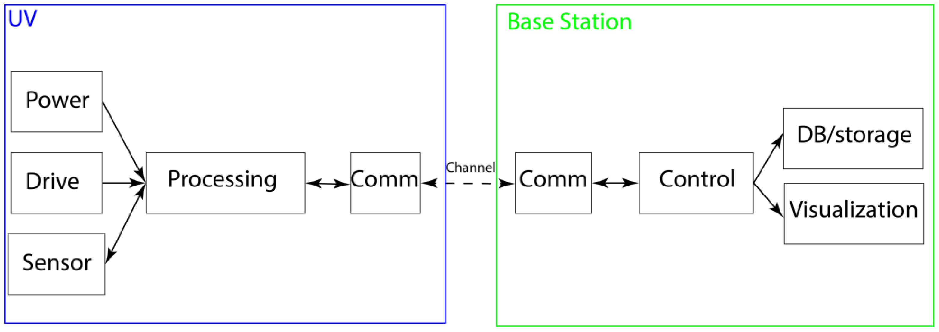
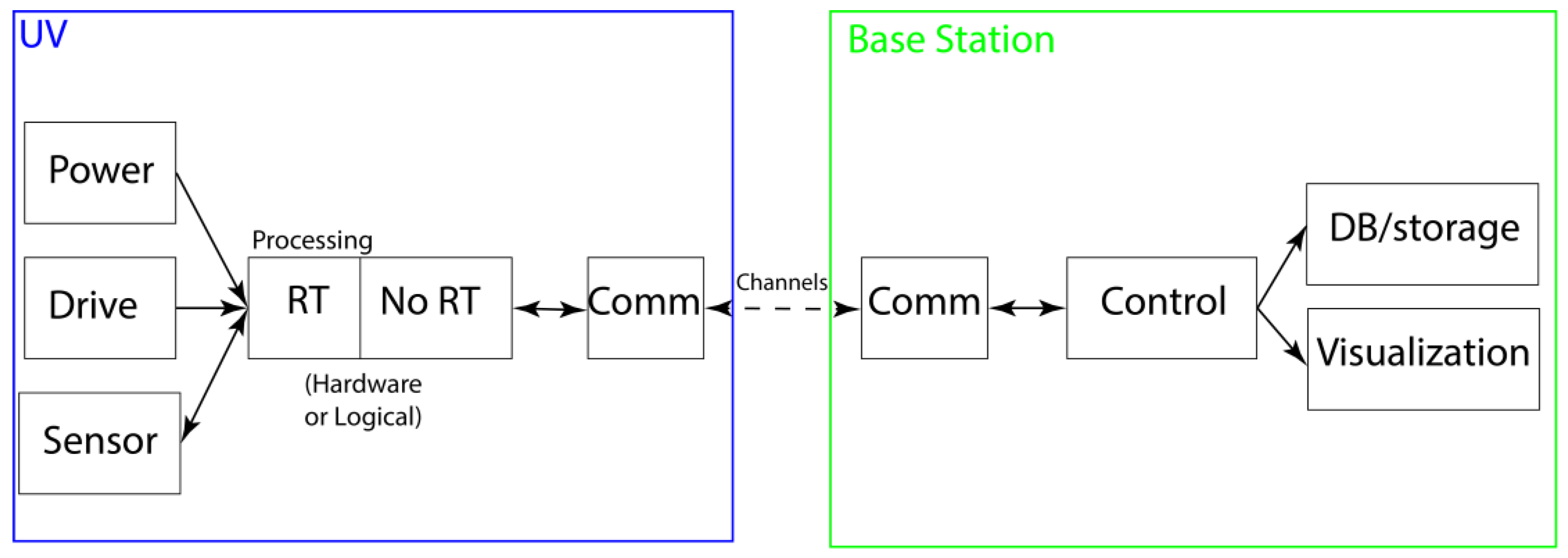
2. UV System Architecture: Version 1
The first version of the proposed architecture for the UV [
20] is shown in
Figure 1. These architectures divide the system into various subsystems. This version establishes the core of the architecture that will be modified according to the proof of concept and the change in the design.
The base station subsystems could be broadly defined as follows:
Communications (“Comm”): Protocols, UV identification, handling of data packets, and both input and output for each UV will have to be implemented.
Storage (“DB/storage”): The data collected by the UVs through the sensors. Depending on the application and computing requirement, it is possible that most of these data will be analyzed asynchronously.
Visualization (“Visualization”): The information needed to inform the user about the different data as soon as they are received and processed by the station.
Control/Synchronization (“Control”): Each of the station systems must have synchronization between, in addition to the need for real-time control over each UV.
In the case of UVs, there are five subsystems, defined as follows:
1. Power: Provides and maintains a stable power supply to ensure the operation of the other subsystems. The supply is provided by one or more batteries, which have a pre-set voltage. As we have several modules with different voltages, it is necessary to use voltage regulators.
2. Drive: Allows the UV to move in different fields (air, ground, etc.). This is thanks to mechanical components such as tires or propellers, in addition to motors with their controllers.
3. Communications (“Comm”): Establish a connection with the base and allow the reception and transfer of movement instructions and data. The communications device will vary according to costs, communications range, etc.
4. Sensors (“Sensor”): Depending on the application or task to be performed by the UV, several sensors or actuators are used. The sensors necessary for operation are not included in this subsystem (for example, an energy consumption sensor).
5. Processing: Controls the UV by synchronizing and controlling all other subsystems in real time. Many of the processes in other subsystems depend on processing information sent by the base station. This subsystem is usually a board with connections to the rest of the UV.
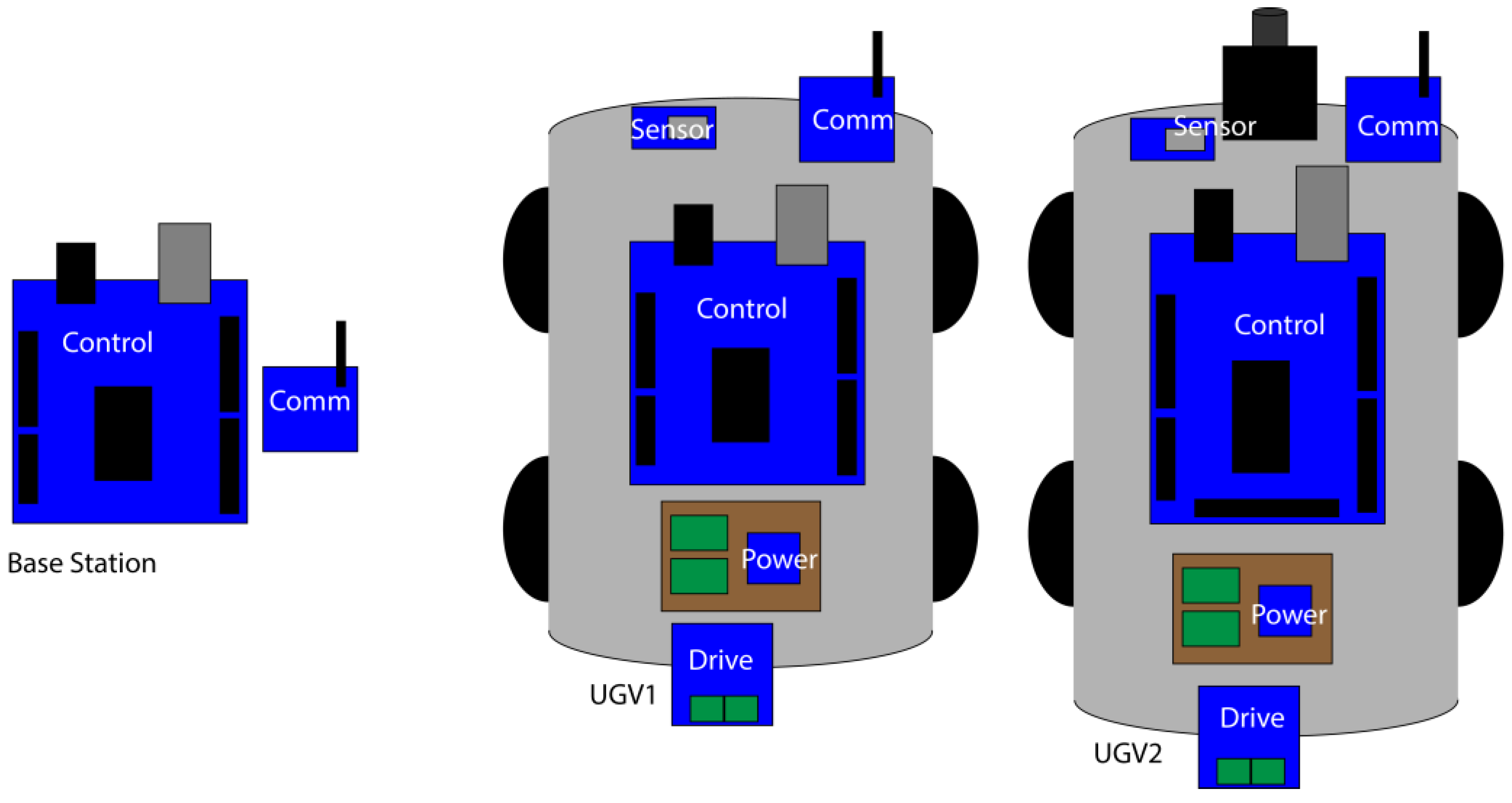
The proposed architecture was validated with a proof of concept. Two vehicles and a base station, equipped with a UV communication repeater, were built (
Figure 2). The UVs (blue and green boxes) of this implementation are shown next to the ground station (red box), which is connected to a PC. The UVs can be specifically classified as unmanned ground vehicles (UGVs), although they have also been called unmanned terrestrial vehicles (UTVs). Despite the different environmental conditions, the vehicles that have been used in planetary explorations (called rovers) have clear conceptual similarities, at least in terms of architecture. The objective of the complete system is to collect photo-graphic samples of a geographical area to be covered with the UGVs. Therefore, the complete system is composed of a sensor vehicle equipped with a camera, a vehicle that acts as a repeater, and the base station.
This architecture generally allows the control of one or several UVs. This control of various UVs, specifically UAVs, can be observed in several previous works. In [
21], a UAV with fixed routes was used to increase the range of the other UVs distributed throughout the area. In [
22], the focus was the control of multiple UVs, while in [
23], the focus was the control of several UVs starting from a mobile single point called the mothership.
This proof of concept showed that it is possible to use the general architecture for building UVs, whether individuals or groups. While using Arduino Mega or Leonardo greatly limits the number of relatively complex sensors and actuators, such as the camera, in our test, it was shown to be functional, and the architecture also allowed the Arduino board to be swapped out for one with greater capacity. In any case, it should be noted that more computing power implies greater energy consumption, so it is a trade-off between the two.
Using a single processing device like Arduino involves limits, and one of these limits is the memory capacity. During the proof of concept for tasks of capturing and transmitting multimedia content (in this case, consecutive image captures), memory was an important limit. This limit forced lower image resolutions in order to not saturate the available memory. Although there was the possibility of expanding the memory with an SD card, for the process of capturing and storing the image on the SD card, it is necessary to have all the memory space to process it.
Additionally, Zigbee was used in the same tests. These communications impose their own limit: in this case, it was the maximum payload allowed per message, which involved fragmenting the image into small packets. This is a common practice but it involves additional processing in the Arduino, as well as additional wait times.
Taking the above factors into account, low-resolution images (160 × 120 pixels) could be sent. It is always possible to overcome the limits imposed by each technology and hardware used. Communications can be replaced, Arduino-based boards can be replaced by more powerful ones with greater memory capacity, etc., but in all cases, there will also be limits imposed by each design and implementation decision, including the energy costs required. This is an example of the challenges involved in selecting the processing unit. In the case of sending, for example, multimedia data, the system presented up to this point does not have sufficient capabilities, so it is necessary to review and adapt the processing subsystem.
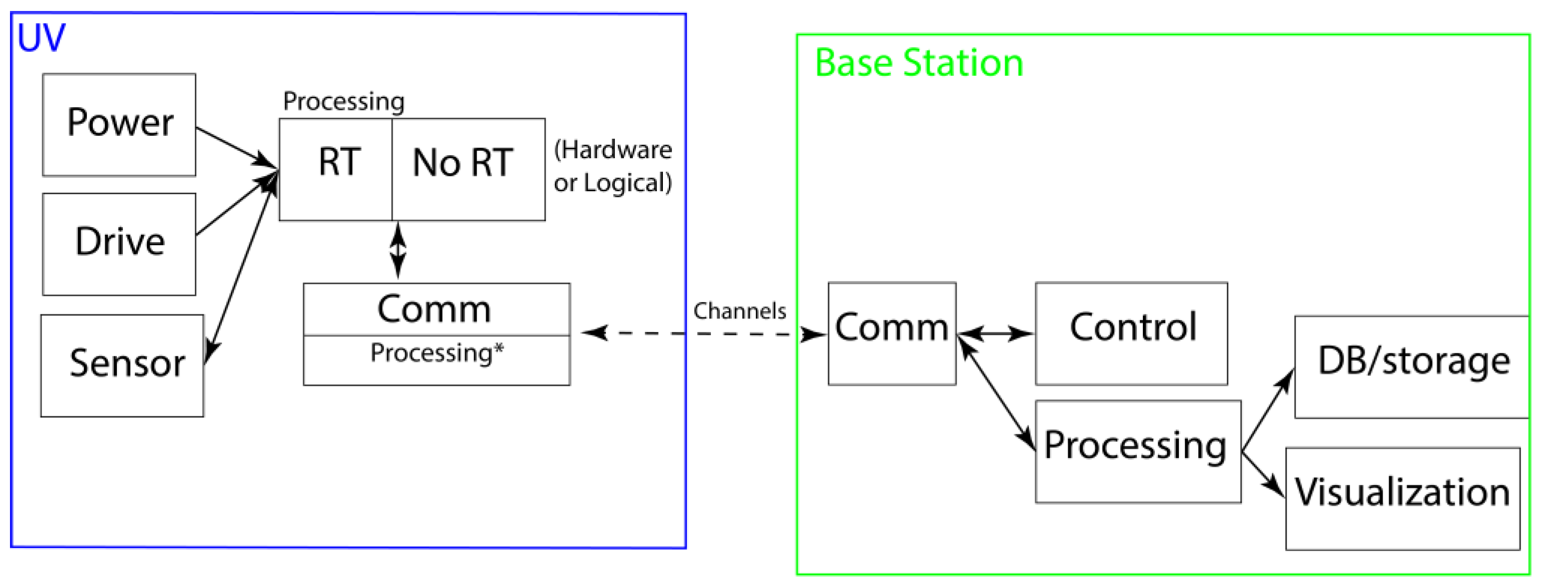
3. UV System Architecture Version 2: Heterogeneous Approach
It is possible to change the device (Arduino) for one with higher capabilities and, at the same time, establish limits on consumption, size, and weight. These limits or characteristics will limit the use and selection of processing devices. There is also the alternative of a heterogeneous solution, which involves the use of two or more devices between which all the required tasks are executed. In that order, the architecture changes to a heterogeneous solution, as shown in
Figure 3 [
24].
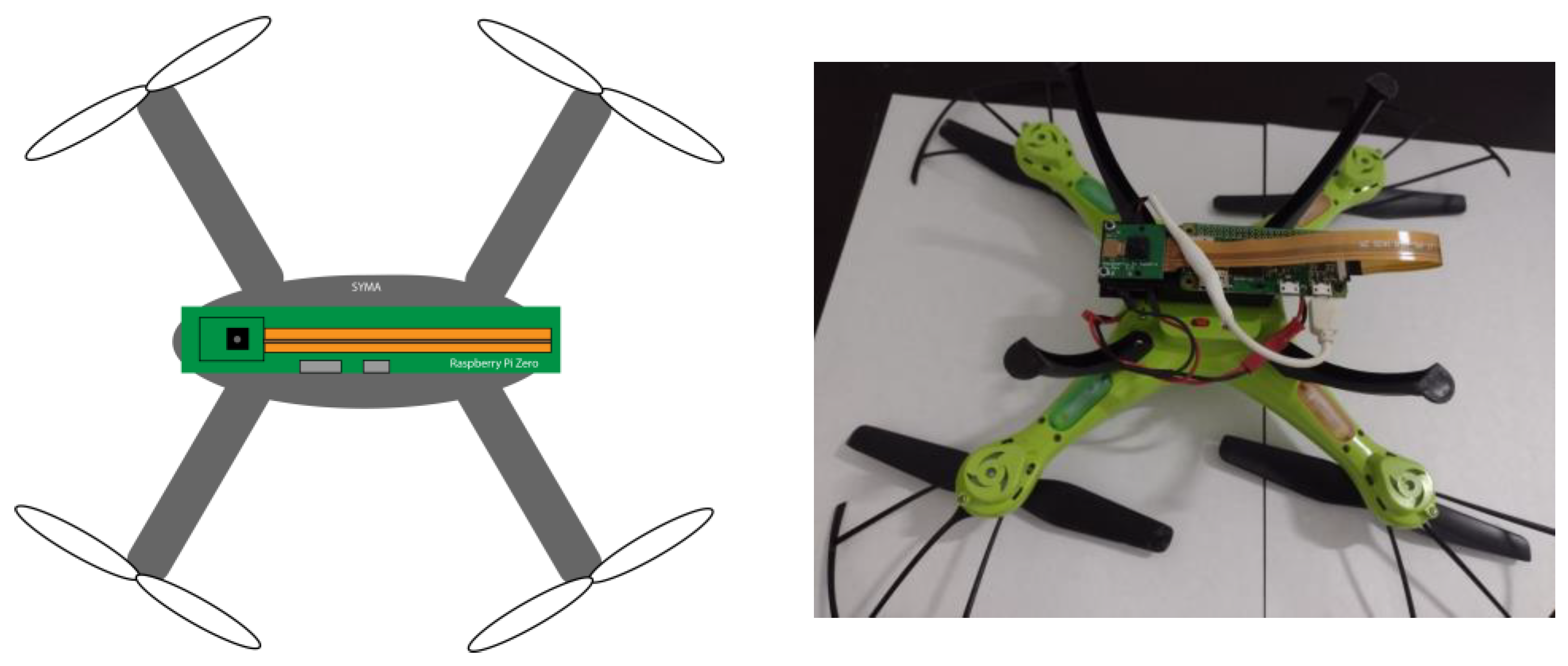
The proof of concept for the architecture is shown in
Figure 4. The SYMA X5HW [
25] was modified by adding a Raspberry Pi Zero W (The Raspberry Pi Foundation, Cambridge, UK) with a camera for image capture (the no Real-Time Part), so the flight controller of the SYMA was left alone in the Real-Time task in the case of the drive subsystem.
Tasks that require real-time processing, such as those identified as “hard real-time” (for example, a flight controller), will be performed by the Arduino board or another board that meets the real-time requirements. On the other hand, tasks that do not require real-time processing or that are of the “soft real-time” type will be carried out by a board with greater capacity, such as the Raspberry, as would be the case of image capture and/or tasks such as encryption or checksum review.
The choice to use Arduino as a flight controller can be found in [
26], while the choice to use Raspberry as a device for video capture and streaming can be observed in [
27]. The use of a heterogeneous architecture using Arduino and Raspberry boards can be seen in [
28] for an irrigation system, while [
29] presents a shell-fishing application. For UGVs, we reference the works of [
30] and [
31], which are the closest to our proposed system in terms of using the architecture for UVs in a general way.
Our proposal implies additional energy consumption from the processing of the two plates, in addition to the extra weight that they impose on the UV, so the power and management subsystems must be adapted and implemented with these new configurations.
Regardless of the use of a Raspberry device as hardware, the heterogeneous architecture will allow the correct execution of tasks, such as flight control and sensory processing. Additionally, it is important to ensure communication channels are not overlooked since, if only one channel is used to send both flight commands and sensor data, the channel can be occupied. The above is the result of making multiple extra shipments, for example, when having to resend an image. This could jeopardize the UV’s stability. This is why having two devices can generate two or more different exclusive communication channels per device, allowing one to be used for everything related to control and the other for the rest of the tasks. These tasks would be, for example, telemetry or information from sensors that are not categorized as hard real time.
This proof of concept shows that the architecture is viable, but, like version 1, presents a limitation. In this case, the limitation is in the base station. It is common for commercial drones of UVs to have closed systems. For Syma, the drive subsystem only works with the app that the fabricators provide, which means extra work is necessary to control all the subsystems from a single base station. The challenge here is focused not only on the use of a heterogeneous approach but also on the integration of the base station and obtaining an equilibrium between weight, power consumption, and processing capability.
4. UV System Architecture Version 3: Base Station Specifications
So far, the evolution of the architecture has been focused on the UV, but it is important and necessary to include the details of the base station. The base station is the part of the system that will provide instructions to the UV, process all the data, and send information to the user. Before showing the final version of the architecture of the UV, two options are presented. The first option involves the modification of the communication subsystem that allows the processing of the movement data. The second option is the evolution of the heterogeneous proposal, now with the option to divide the RT and no RT tasks using logical or hardware solutions. This approach is also used in the first option.
The first option is based on the fact that commercial FCs offer flight stability. However, in all cases, manual operation is maintained, which is known as “Man in the loop”. Therefore, the option of using a commercial FC but intervening in the interaction between the control and communication submodules can be considered, consisting of changing the “manual” operation mode to a (more) autonomous flight mode, as initially programmed. With this, the aim is to obtain an intermediate system in which the “Man in the loop” is no longer mandatory for the continuous operation of the drone. In this way, an operator can be dedicated to the tasks of a higher level of abstraction without having to deal with minor details such as flight correction/stability. The detailed implementation is found in [
32].
The proof of concept starts with taking a 6-channel 2.4 GHz commercial receiver (the FS-IA6B [
33]) and a 6-channel RC controller (Flysky FS-I6 [
34]) as a reference. A study of the signals that the receiver sends to the FC according to the commands or operations of the manual control was performed. This study allowed us to replace the receiver with a NodeMCU [
35] and a Quad 2-Input AND Gates CD4081 [
36]. The AND gates are needed to implement “glue logic” to guarantee that all the signals are synchronized on the rising edge independently of the delay generated by the NodeMCU to handle them individually.
Replacing the receiver with the developed one allowed us to take advantage of the stability and control solutions provided by commercial FCs to a certain extent, and by using the tools that these already have, such as configuration and calibration software, it allowed us to obtain a test environment before the flight, reducing the risk of failure. On the other hand, commercial receivers are devices designed and optimized for this specific function, in addition to having the interaction with the operator as input. The latter was quite a challenge since it involved making adaptations at the level of command execution times to obtain response times closer to those of an operator, an example of which is the inclusion of delays when unlocking the engines. In general, this is a limitation since the commands of the developed receiver can be sent at time intervals shorter than those of the operator. This approach of the UV and the base station is shown in
Figure 5.
In this architecture, communication channels are observed between the base station and the UV. Normally, there is a channel for UV control but this task requires hard real-time operations, so having an exclusive channel avoids delays due to interference from other commands or message queues due to shared use of the channel. The other communication channels between the base station and the UAV are used to transfer data such as images from the UV to the base station. Tasks are performed in parallel at the base station (control and processing of incoming data). In this last task, a local or cloud service can be used, such as for image recognition. In view of the limited resources of the UV, the data are saved after being received at the base station for processing. Finally, in each application, it is necessary to determine the status of the UV and the result of the system’s task or mission; for example, in the case of a search and rescue mission, the user is informed of the detection of the found person.
The second option (
Figure 6) is the continuation of the heterogenous approach. For this option, a proof of concept was developed using the Ryze Tello drone [
37] as the UV. This UV is equipped with a 5 MP camera, with a flight time of 13 min, a maximum height of 30 m, and control through its own SDK, which allows:
- -
Programmed control, which is essential for the UAV’s path/mobility, with stability provided by its own flight control system.
- -
Programming of/for scalar or multimedia data.
- -
Basic automatic functions such as takeoff, landing, and maintaining the flight position or hovering (referred to as “hover” in the literature).
The details of the proof of concept of this architecture can be found in [
38], which was based on the implementation of a search and rescue application using the proposed architecture. In the field of search and rescue applications using UAVs, there are many related works. For example, in [
39], an application for a search operation at sea using UAVs was described. Likewise, in [
40], they presented 3D mapping using UAVs with the objective of improving the planning and execution of search and rescue operations. Regarding search planning, in [
41], they designed a system for post-disaster scenes, and in [
42], they referred to the importance of the user interface in UAVs and user interactions to improve results in search and rescue. Likewise, in [
43], they focused on the transmission of high-quality images to be processed at the base station for search missions. Moreover, in [
44], the work emphasized path planning for UGVs in search and rescue missions for mines. The above is a sample of works with different focuses, either as search and rescue operations in a specific situation or in the planning of operations. All these works have the presentation of the problem, the solution, the validation of the solution, and the conclusions in common. They do not describe the architecture or the processes in detail, although in some cases, they define the architecture as the interconnection of the components. In all cases, it is expected that what is presented will be reused as it is, without the possibilities of adaptation, improvements, changes, or optimizations since no details are given in this regard.
In general, the results of the proof of concept demonstrate the correct functioning of the application and the architecture. Although its operation for this proof of concept is limited due to the battery capacity of the UAV and depends on an external connection and service for image classification, the complete system works and produces the desired results.
5. Conclusions and Future Work
Different proofs of concept have been shown for different UV system architectures and different types of UVs, more specifically UGVs (ground vehicles) and UAVs (air vehicles). Finally, a complete system and proof of concept of a search and rescue application were developed following the proposed architecture.
Accurate measurement of the different components of the architecture not only allows for the calculation of operation time but also helps in device comparison analysis to improve the performance of the UAV. By clarifying the different parts or subsystems involved in a UV application architecture, such as the one presented, the implementation of the architecture can be adapted to the application to be carried out. The most direct and clear example is changing the type of UV according to the medium in which the vehicle must move, such as on land (UGVs), in the air (UAVs), on the surface of water (USVs), or underwater (UUVs). In the same way, we can change other parts of the system, such as the power required, identification of hard real-time tasks, etc.
The use of a heterogeneous architecture is not only viable but also provides flexibility in the implementation of applications. A specific case could be the capturing and processing of scalar or multimedia data without having to “sacrifice” the stability or operability of the UAV. In all cases, we must consider that more devices also lead to higher energy consumption and additional weight.
This paper shows the general architecture of the system and possible adaptations for different types of processing and unmanned vehicles. In addition, the system manages to combine a command-and-control system at the base station with developed software for control, image processing, and system interface.
The lines of research remain open for the future. We recommend that future research explores whether increasing the number of UVs is viable, wherein not only is the extension of the operating limit obtained but also other data transmission times. Also, UGVs were used in the proof of concept, but other types of UVs such as UGMs or UMVs could be experimented with, as well as heterogeneous combinations of UVs (e.g., UGV + UAV or UAV + USV). This will allow the proposal of new general or specific architectures for each type of vehicle.

