1. Introduction
Rail transportation plays a substantial role in the economic development of many countries. Metro, subway, and high-speed trains are environmentally friendly transportation systems that are often used to enable long-distance, local, or smart city mobility [
1]. The speed and number of trains on high-speed railways have increased in modern transit systems, and consequently, track defect inspection has become increasingly essential for ensuring passenger safety [
1,
2]. Rail transportation organizations regularly use a variety of manual inspection procedures, among which visual inspections and testing with gauges are the most common. Manual inspection devices are straightforward and reliable but have slow measuring speeds [
3]. Additionally, manual inspection enables the assessment of only small, short-track railway sections and does not allow for full track measuring or ongoing track monitoring. These shortcomings have led to greater investment in the study, development, and application of self-propelled railway inspection vehicles [
4].
Modern inspection technologies utilize advanced sensors, including ultrasonic sensors, LiDAR, and cameras, to detect defects like surface degradation, irregularities, and fastener failures with high precision [
5]. Current rail surface testing equipment has been introduced in the form of the Felix track inspection robot, the JDT track inspection robot, and the self-propelled inspection kart RailPod [
4]. However, researchers studying these smart inspection vehicles face challenges in managing lateral dynamics and maintaining the operational stability of the device during operation under various damaged track conditions.
In recent years, research on active steering control methods for railway vehicles has received much attention from researchers who want to enhance the stability and performance of autonomous railway vehicles. Recent research on active steering control for railway vehicles has focused on optimizing stability, reducing wear, and improving operational efficiency. Tian et al. (2020) proposed a minimum wear number-based control strategy, enhancing wheel–rail interaction and extending service life [
6]. Later, Tian et al. (2023) explored advanced control structures to improve vehicle maneuverability [
7]. Fu et al. (2020) investigated wheelset steering from a wear evolution perspective, while Kalivoda et al. (2021) assessed active steering performance using simulations and roller rig tests [
8,
9]. These studies highlight the growing emphasis on intelligent steering solutions, forming the foundation for further advancements in hybrid and autonomous railway systems. Although these methods provide improved feedback and tracking accuracy, they often require significant energy input and complex computations. Moreover, most active steering systems ignore the natural self-guiding forces of the wheelset, such as slip force and normal force, which can contribute to stability with lower energy requirements. One of the fundamental challenges in railway vehicle dynamics is ensuring lateral stability while minimizing computational complexity. Traditional vehicle motion equations rely on simplified linear approximations that often fail to capture the nonlinear interactions between the wheelset and track, leading to higher positioning errors and stability issues.
To address the challenges of maintaining stability in autonomous railway inspection vehicles, this study proposes an advanced hybrid steering control system, which integrates the self-steering capability of the wheelset with an active steering controller based on fuzzy logic. This system is specifically designed for a micro-autonomous railway inspection vehicle, optimizing lateral stability and minimizing deviation from the track centerline.
The conical wheelset inherently enables self-steering on curved tracks. However, when traversing rail surface defects or sharp bends, the difference in contact radii between the two wheels on the same wheelset can lead to hunting motion (undesirable lateral oscillations), compromising inspection accuracy and operational safety [
10]. In this study, we propose a novel set of vehicle motion equations that integrate the natural self-guidance properties of the wheelset with an adaptive fuzzy logic controller (FLC). This approach enables more-accurate modeling of lateral dynamics and reduces the reliance on frequent corrective control inputs. Compared to conventional equations, our method offers several advantages, including lower positioning error, improved real-time computational efficiency, and enhanced stability under varying track conditions. The proposed hybrid steering system actively adjusts the torque distribution between the drive wheels, leveraging the natural self-steering forces of the wheelset to maintain stability while avoiding the high energy consumption typically associated with conventional active steering methods.
This study not only developed an enhanced mathematical model but also conducted detailed simulations using SIMPACK and SIMULINK to evaluate system performance. By integrating intelligent control strategies with wheel–rail dynamic modeling, this research aimed to overcome the limitations of existing autonomous railway inspection methods while introducing a novel hybrid approach that enhances precision and efficiency in railway maintenance technologies.
2. Mathematical Model of the Lateral Dynamic System
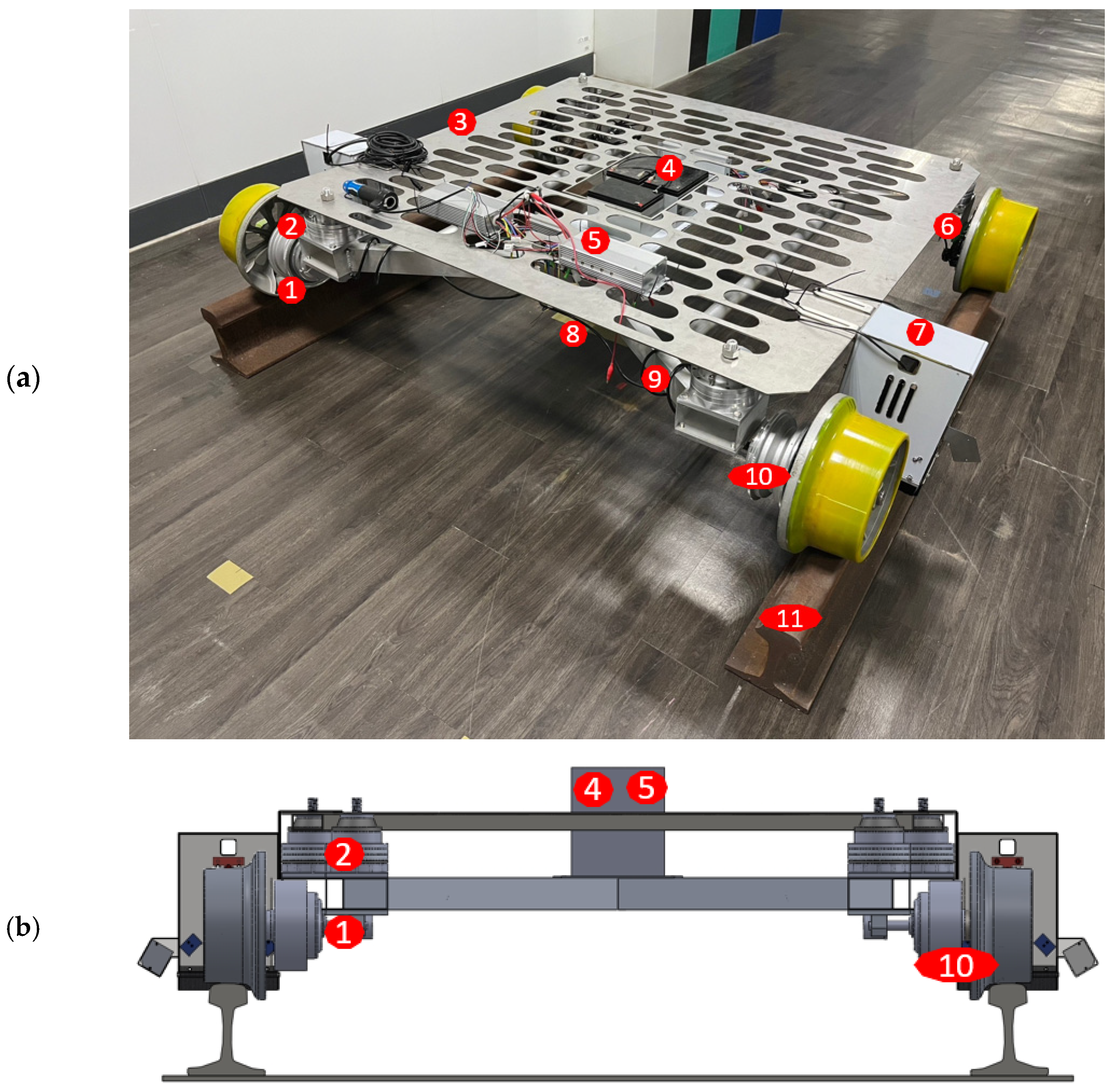
The structure of the proposed autonomous inspection vehicle was designed to enable easy installation or moving off the track by humans or robots; its size and weight were minimized to the greatest extent possible, as illustrated in
Figure 1a. The car was 1360 mm long, 1602 mm wide, and 340 mm high, with a wheel profile that followed International Union of Railways code 510-2 to fit a typical track gauge (EN-60 rails) of 1435 mm. The vehicle had a total mass of 200 kg and operated at a speed of 30 km/h.
The vehicle was compact, lightweight, integrated, self-driving, and stable, with rapid detection and a cutting-edge intelligent inspection system involving camera and laser technology.
Figure 1a illustrates the layout of the vehicle components and systems. Additionally, a gauge sensor was used to determine the rails’ offset, and artificial intelligence deep learning techniques were applied to increase the accuracy of recognition of rail wear and fastener fault. The vehicle adopted a magneto-rheological mount system (MR mount) designed to reduce vertical vibration during vehicle operation, increasing stability to meet the inspection system’s working requirements [
11].
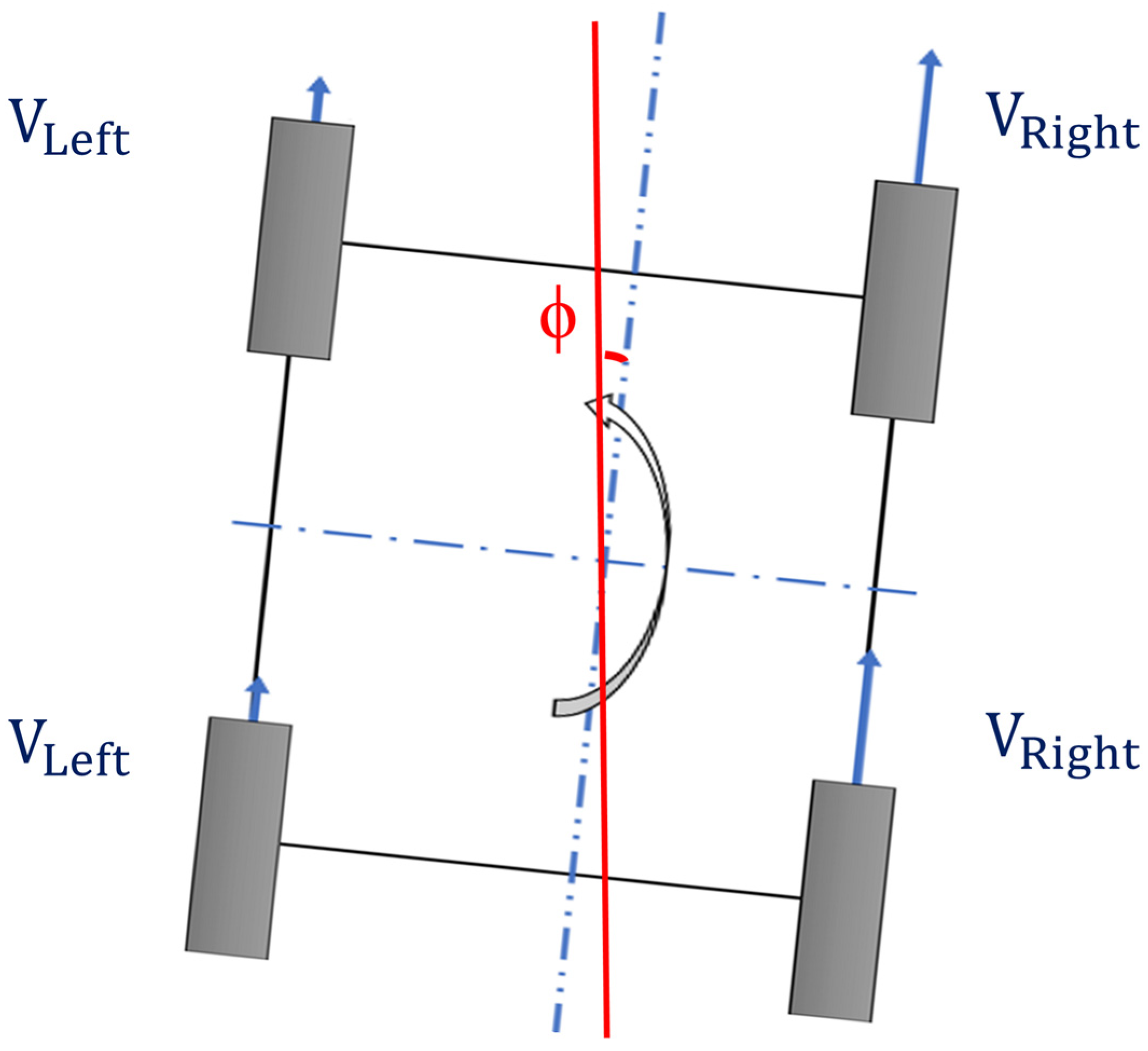
DC motors on the two front wheels were used to steer the vehicle, as presented in
Figure 1b. To reduce vehicle weight, the wheels were made of aluminum and covered with polyurethane to prevent damage during operation. Speed control of the two DC motors was used to control the transmission and guide the vehicle.
2.1. Wheel and Rail Contact
The Hertzian normal contact theory and Kalker’s linear theory were used to calculate the movement of the vehicle’s center while in motion by analyzing wheel axle movement during wheel and rail contact [
12,
13,
14]. A mathematical model of the vehicle was then derived using these equations. To assess lateral dynamics, the vehicle was assumed to proceed down the track at a constant speed of v = 30 km/h. The MR mount detection system was employed to swiftly reduce the vehicle’s vertical vibrations, ensuring stability in the vertical direction [
11]. Given the effectiveness of this system in mitigating vertical oscillations, we assumed that vertical vibrations were nonsignificant in our analysis. Consequently, this study focused exclusively on the lateral dynamics of our micro-autonomous railway inspection vehicle, incorporating its unique design and hybrid steering control system. By leveraging the MR suspension to stabilize vertical forces, we were able to concentrate on analyzing lateral forces, the wheelset’s self-steering behavior, and the hybrid control system’s performance in maintaining track alignment.
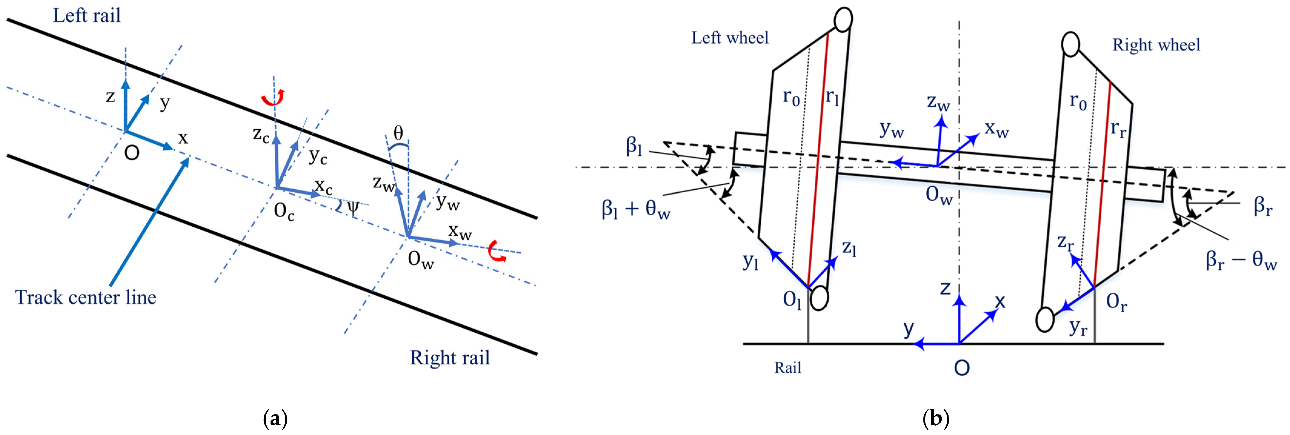
The vehicle coordinate systems of this study are presented in
Figure 2. Oxyz denotes the wheelset coordinate system at the center of the track during movement at a constant speed relative to the fixed reference frame of the track. O
cx
cy
cz
c denotes the coordinate system at the center of the car. O
wx
wy
wz
w denotes the coordinate system at the center of the wheelset axle. O
lx
ly
lz
l and O
rx
ry
rz
r denote the respective coordinate systems attached to the instantaneous contact points of the left and right rails and their wheels. β denotes the contact angle between the wheels and rail.
θ denotes the roll angle of the wheelset axle rotation around the x-axis during motion.
ψ denotes the yaw angle of vehicle rotation around the z-axis during motion. Wheel/rail normal and tangential contacts, which control the vehicle dynamics, change as a result of the geometry at the point of contact [
15,
16].
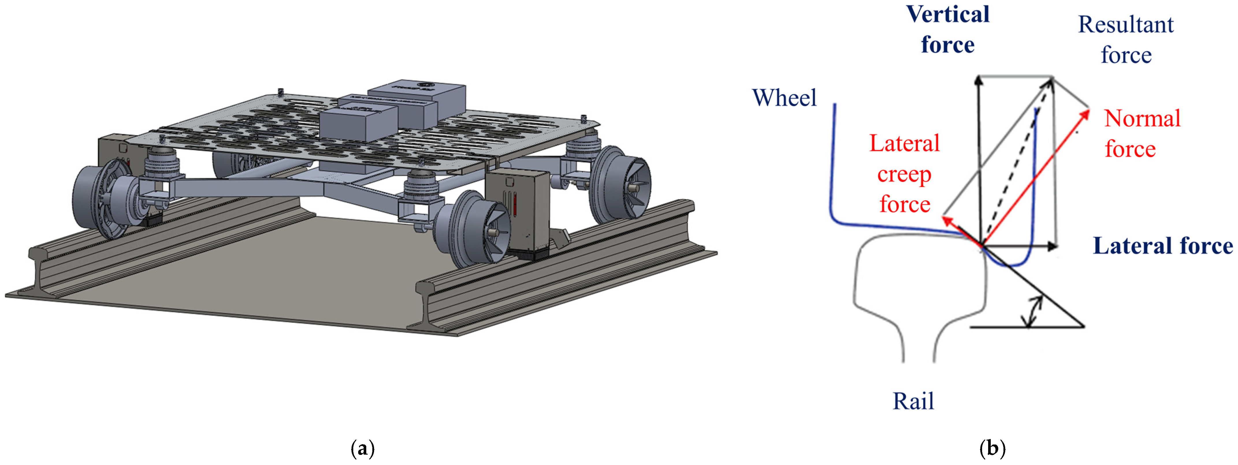
The main forces ensuring a train remains in place on a track when stopped or traveling at a steady pace include creep force and normal force, as shown in
Figure 3 [
17,
18]. The term normal force (
Fn) refers to the force exerted by the rail upward onto the train’s wheel and is perpendicular to the contact surface. Creep force (
Fc) at the wheel–rail contact refers to the small amount of relative motion or slippage that can occur between a train’s wheel and the rail’s contact surfaces. The term lateral creep force (
Fyc) refers to the lateral movement of the wheel on the rail, which is particularly common when the train navigates curves, due to the differences in radii between the curvature of the track and the wheel profile. Lateral creep force enables the wheels to align with the curve while maintaining proper contact.
The interaction between the wheel and rail involves both normal forces and creep forces, each playing a crucial role in the vehicle’s lateral dynamics. Due to the complexity of their behavior, these forces are analyzed separately before being incorporated into the overall motion equations.
2.2. Nonlinear Creep Forces During Wheel and Rail Contact
The equations presented in this section are derived from established fundamental theories in wheel–rail interaction modeling, specifically Hertzian contact theory and Kalker’s linear theory [
19]. Hertzian theory defines the normal contact pressure distribution between the wheel and rail, while Kalker’s theory provides a linearized approximation of creep forces under small creepage conditions. These theories have been widely validated and serve as the theoretical foundation for analyzing creep forces, as presented in the following equations.
Creep forces in the x/y direction
and moment in the z-axis
at the position of contact between the rail and wheels were determined using Kalker’s linear theory, which is expressed as follows [
18]:
where
,
, and
denote the creep coefficients reliant on the geometry at the contact point between each wheel and the rail. The Kalker coefficients
C11,
C22,
C23, and
C33 were calculated using lookup table interpolation based on the SIMPACK dynamics model.
,
, and
denote the longitudinal, lateral, and spin creepages, respectively. Subscript i is used to represent the left (l) and right (r) wheels.
where
G is the rigidity modulus of the wheel and rail material.
A is the contact area between the wheel and rail at the point of contact.
Creep forces primarily depend on creepages (
ξ), which represent vehicle speed and wheelset movements on the rail [
14,
19].
where
are the radius of the left and right wheel at the point of contact with the rail.
is the nominal radius of the wheel.
,
are the contact angles between the left and right wheel, respectively, and the rail.
v is the velocity of the vehicle. Following the Hertzian contact theory,
denotes the wheelset rolling angle, which was calculated from the difference between the rolling radius of the left and right wheels [
19].
is the track width.
2.3. Normal Forces During Wheel and Rail Contact
On the basis of the assumption of static force equilibrium, the vertical forces on each tire in the simplified vehicle model were used to calculate wheel loads. The normal force
N, which is the only source of vertical force, was calculated as follows:
where
denotes the wheel load, m is the mass of the vehicle, and
. The lateral normal forces
were obtained using the following right and left wheel motion equations:
2.4. Differential Equation of Motion
The micro-autonomous railway inspection vehicle in this study features a magneto-rheological (MR) suspension system, which plays a crucial role in stabilizing vertical forces. Due to the MR system’s ability to effectively mitigate vertical oscillations, the influence of longitudinal forces can be considered negligible in the motion analysis. As a result, the vehicle’s dynamic equations are formulated primarily in the lateral direction, focusing on lateral displacement and yaw angle.
We conducted analyses of wheel–rail interaction, particularly accounting for nonlinearities from wheel and rail profiles and adhesion constraints affecting creep force and creepage relationships [
19,
20,
21,
22]. The coordinate transformation is required to convert these creep forces from the contact coordinate system to the track coordinate system, enabling a better understanding of the car’s dynamics on the track, which can be expressed as follows:
where
k denotes the coefficient to convert the model into a Shen–Hedrick–Elkins’ nonlinear creep force model [
14,
19].
The unlimited resultant creep force was calculated using Kalker’s linear theory, expressed as follows [
19]:
The total force and moment acting on a single wheelset were calculated as follows:
where
denotes track width and
denotes the wheelbase, given that the wheels were directly connected to the bogie frame without any primary suspension.
denotes the centrifugal force acting on the vehicle during cornering, which is determined by the bend radius of the track, for which
. The total force and moment of the bogie with two wheelsets (
f = front and
b = back) were obtained using rigid body dynamics and calculated using the following:
The lateral displacement on the front and rear wheelsets (
was calculated as follows:
3. Lateral Steering Dynamic Simulation
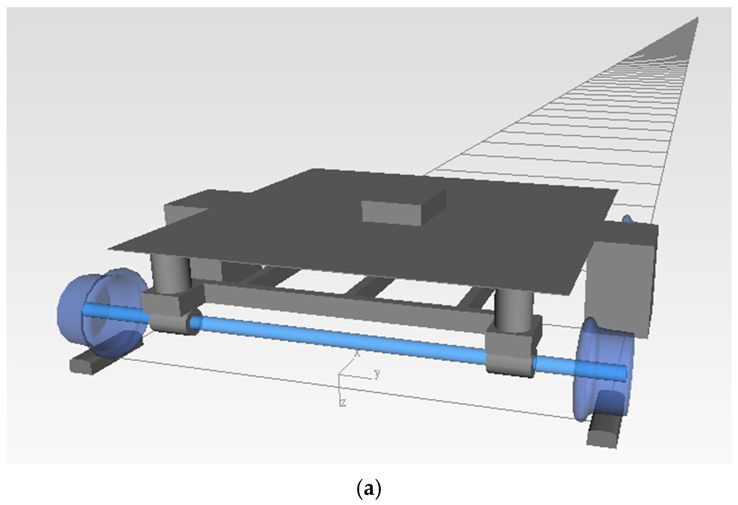
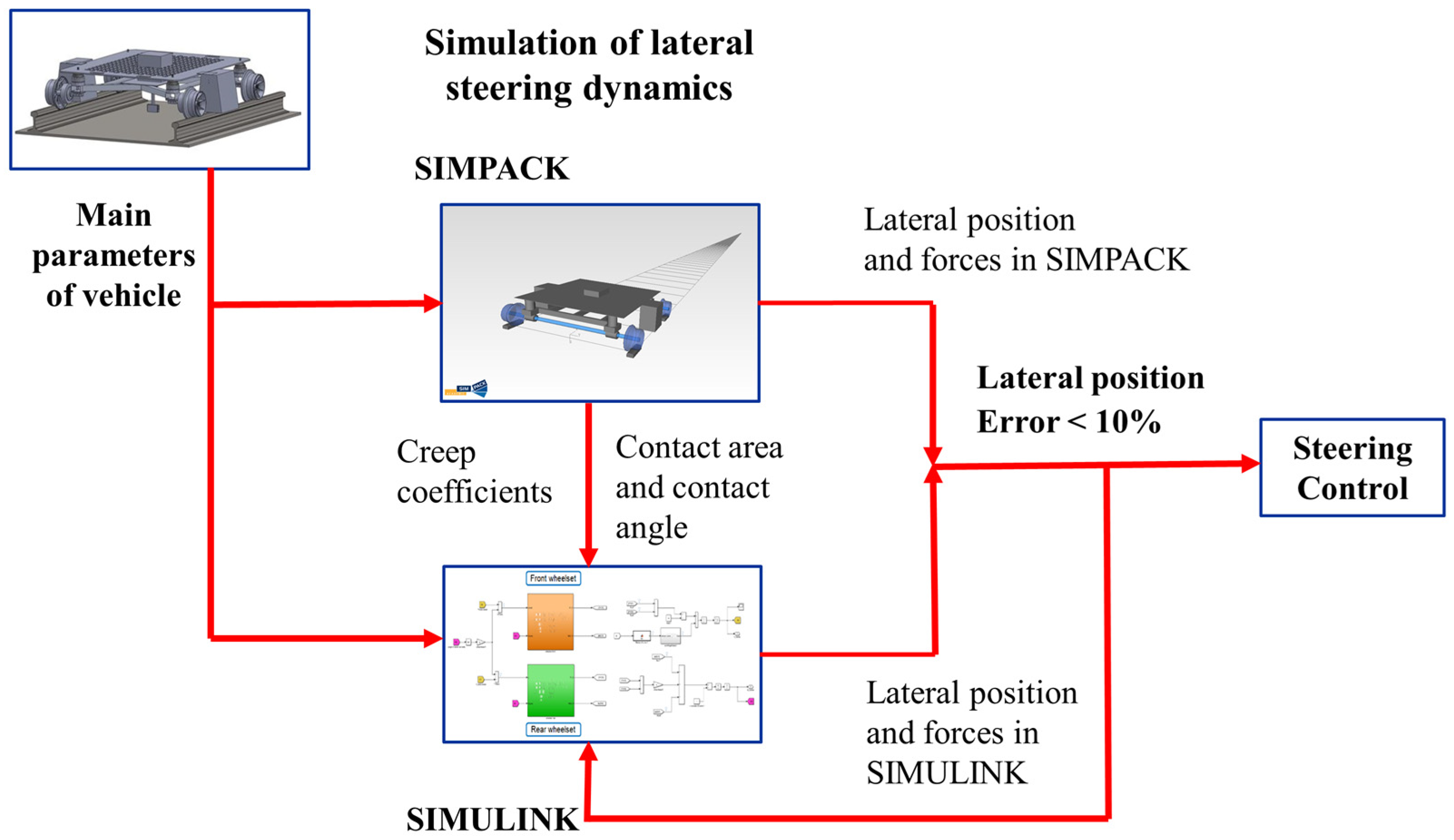
The simulation model was developed based on the key structural design parameters of the inspection vehicle, as summarized in
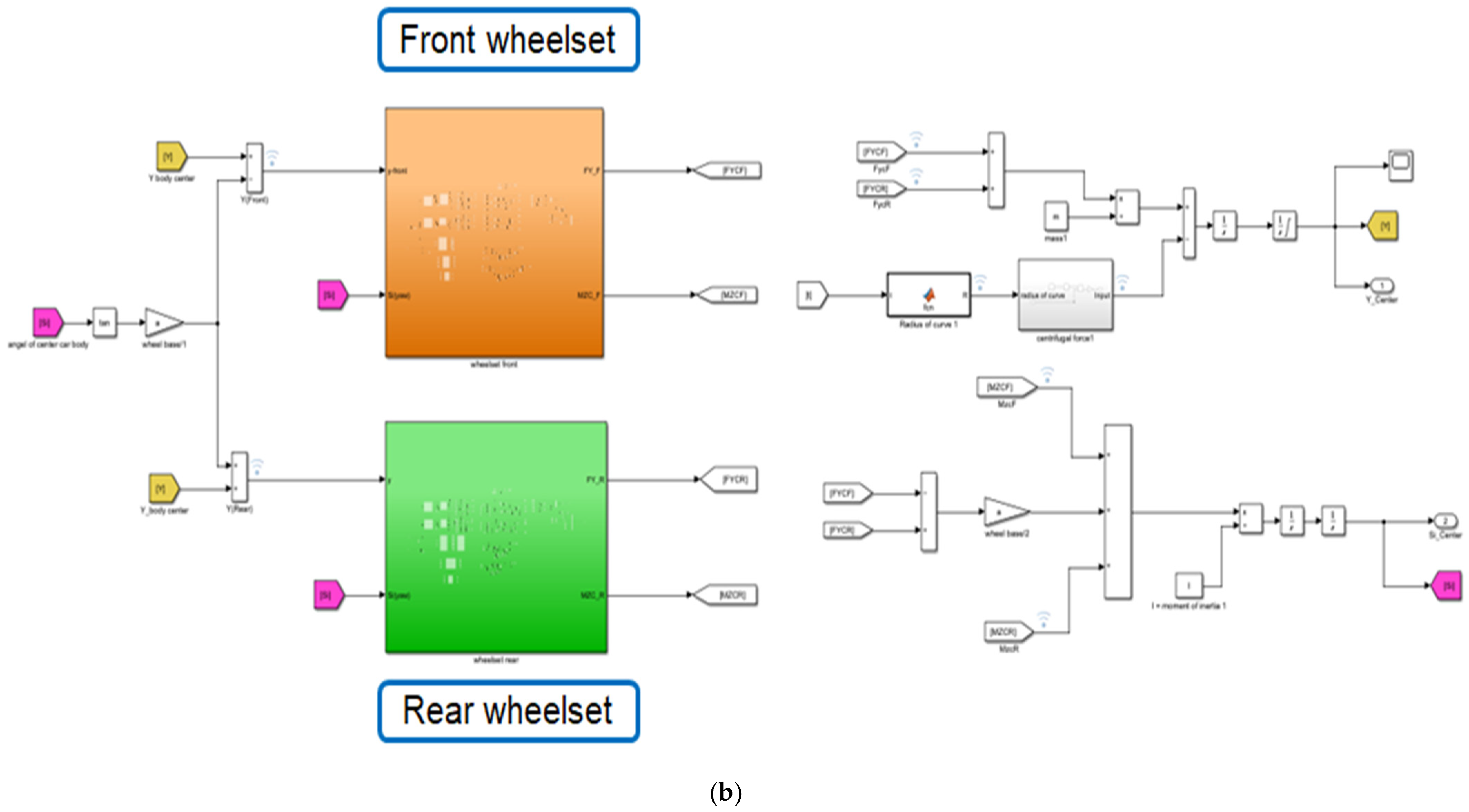
Table 1. Using these parameters, two models were constructed: a multibody dynamic model in SIMPACK and a control system model in SIMULINK, as illustrated in
Figure 4. Two simulation models of the new track inspection vehicle’s operation were built on Simpack and Matlab/Simulink to evaluate the self-guidance capability of the wheelset based on Hertzian norm theory and Kalker’s linear theory.
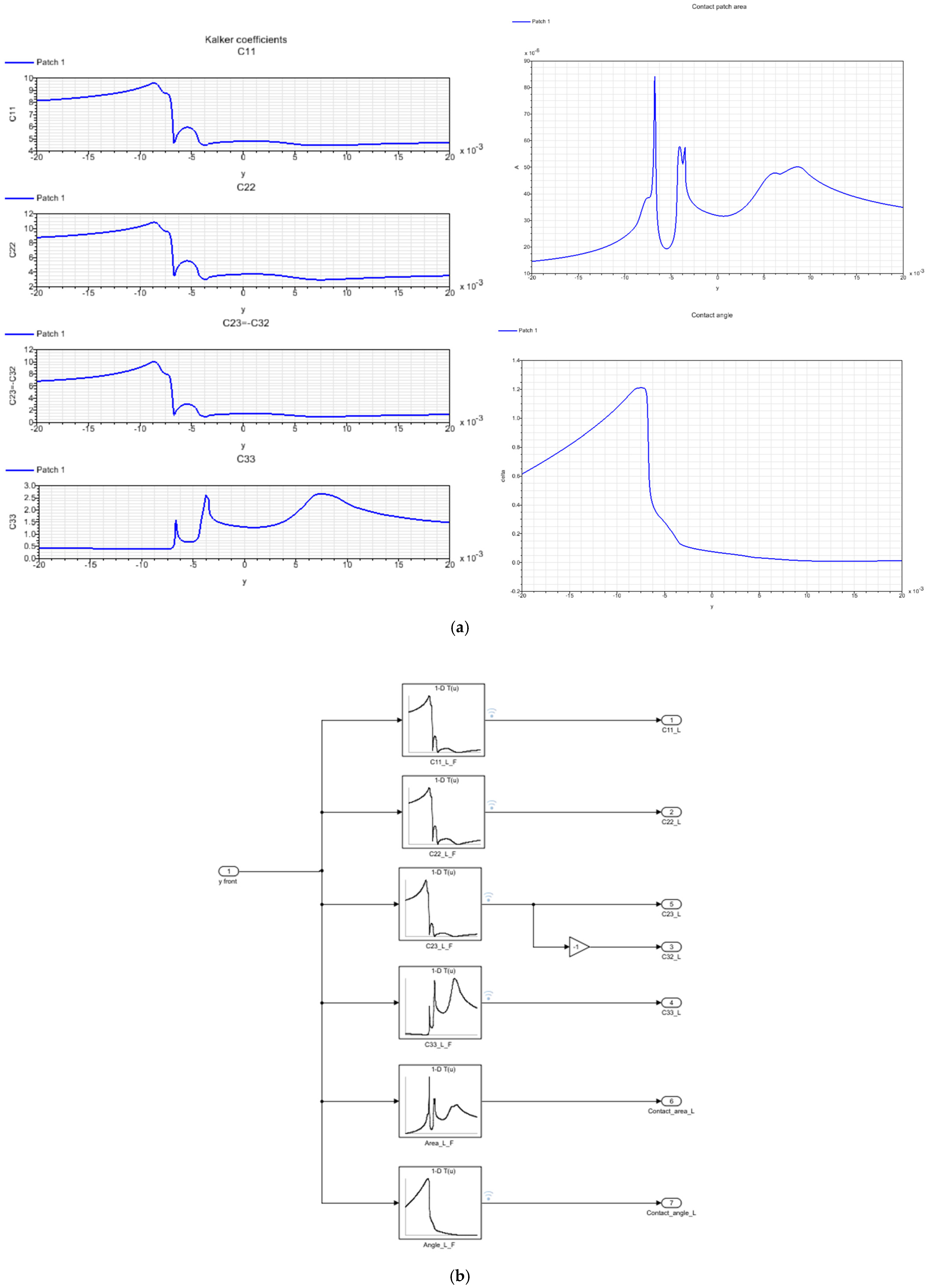
From the wheel and rail profiles of the simulation model of the vehicle in SIMPACK, SIMPACK allows for the values of the following parameters to be derived: Kalker coefficients, the contact area, and the contact angle between the wheel and rail corresponding to each value of lateral displacement of the wheelset’s axle center.
Figure 5a gives information about the above parameters corresponding to the horizontal displacement value at the center of the wheelset for the left wheels from −20 mm to 20 mm, respectively, with 0 mm being the position of the center of the track. From the values of the Kalker coefficients, contact area, and contact angle corresponding to the left wheels, lookup tables were built in SIMULINK, as shown in
Figure 5b. Similarly, the parameters of the right wheel were obtained.
3.1. Running on a Straight Track
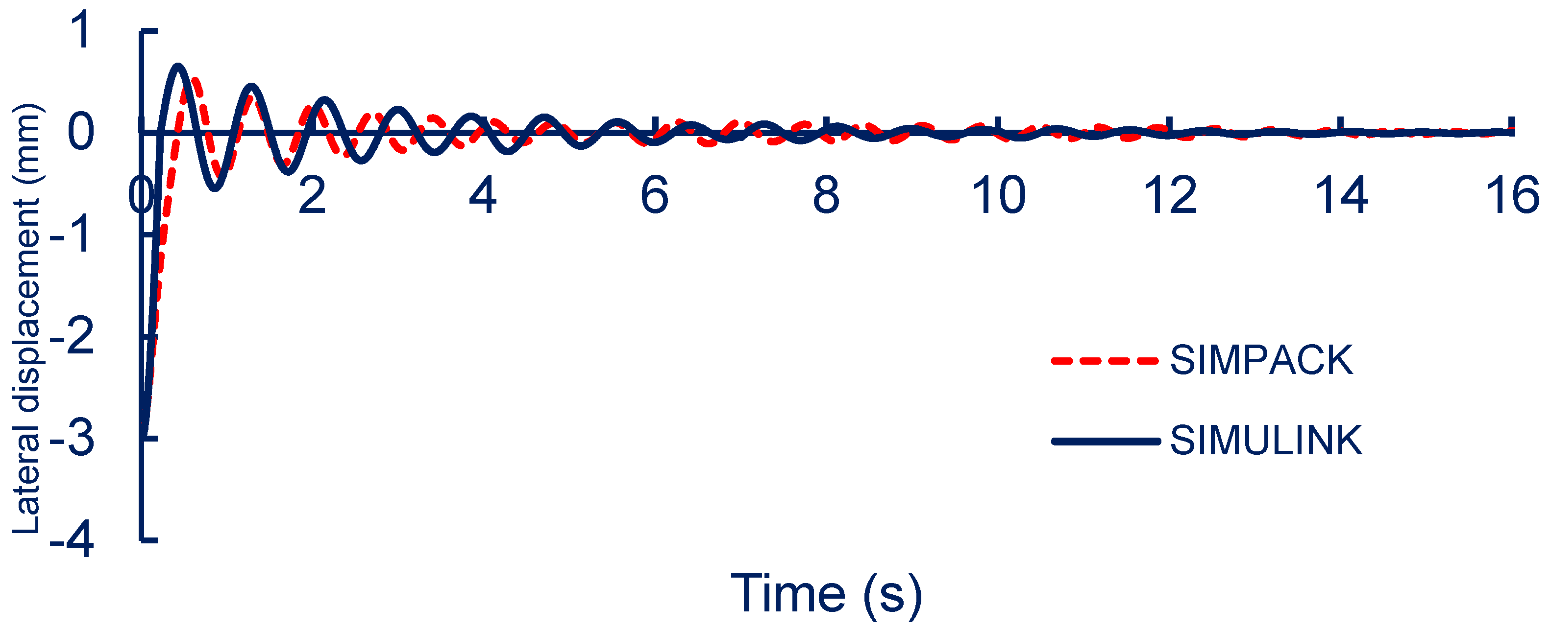
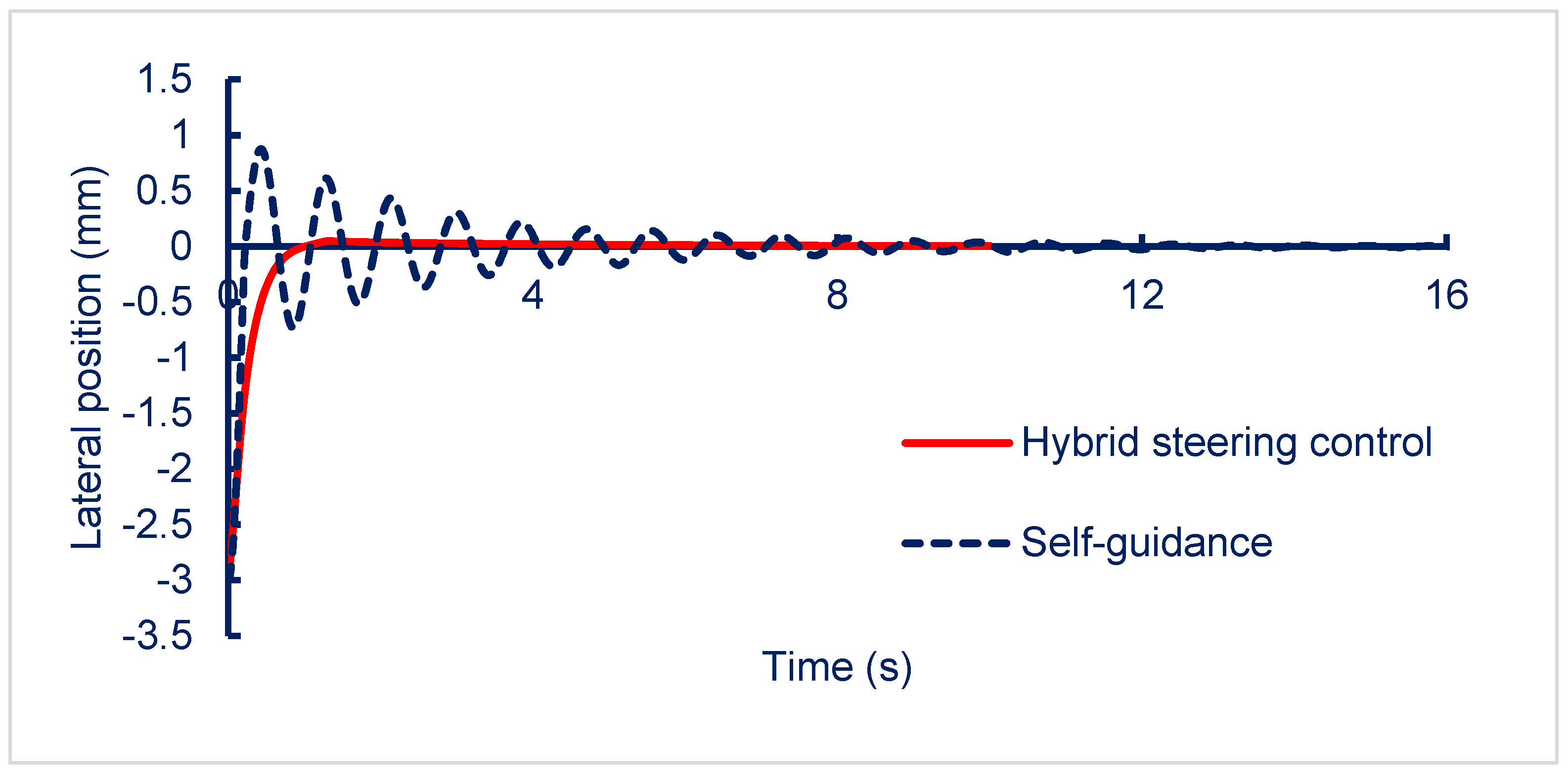
The stability of the inspection vehicle when running on a straight track at an assumed speed of 30 km/h was simulated to assess the conical wheel’s self-guiding potential in various vehicle states. A 3 mm lateral disturbance was applied to the wheels. The lateral displacement of the vehicle center on the rail during movement on a straight track is illustrated in
Figure 6.
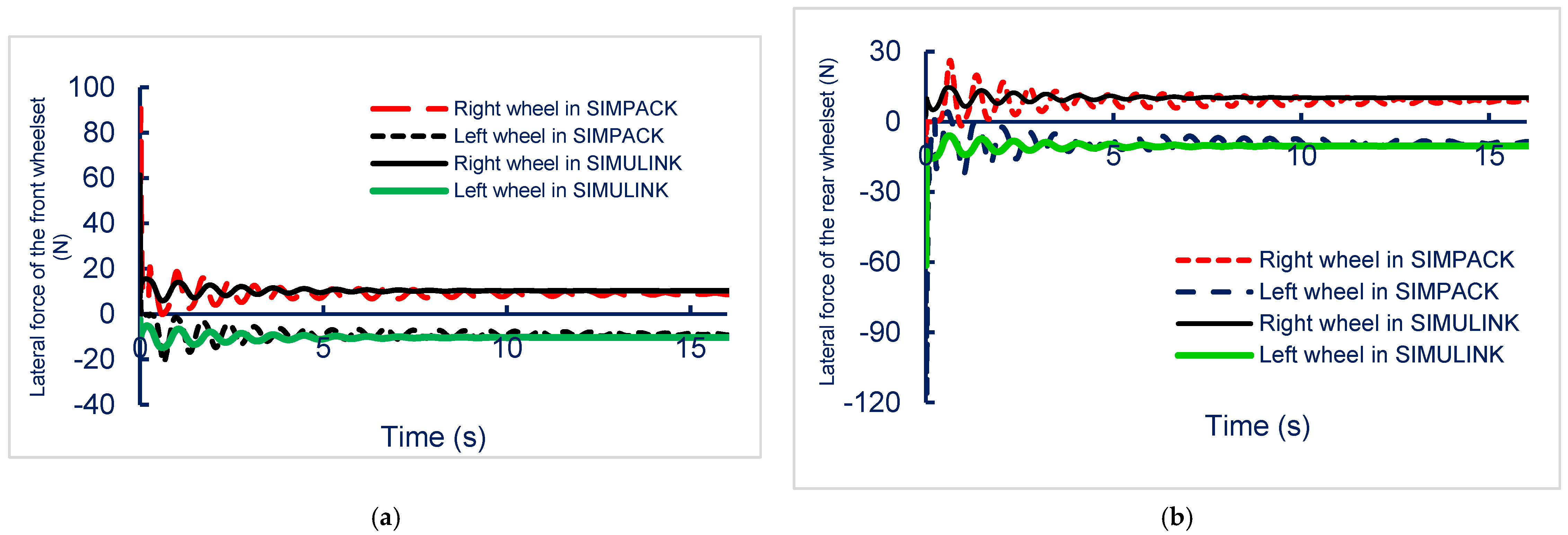
The lateral forces acting on the wheels, as shown in
Figure 7, illustrate the vehicle’s response to a 3 mm disturbance. The results indicate that while the vehicle successfully returned to the central track position, it exhibited a slow response time, continuous oscillations, and steady-state errors. These issues can be attributed to the vehicle’s modest weight, which led to insufficient normal force to dampen wheelset variations. Additionally, the inadequate steering forces contributed to the observed steady-state errors, prolonging the stabilization process.
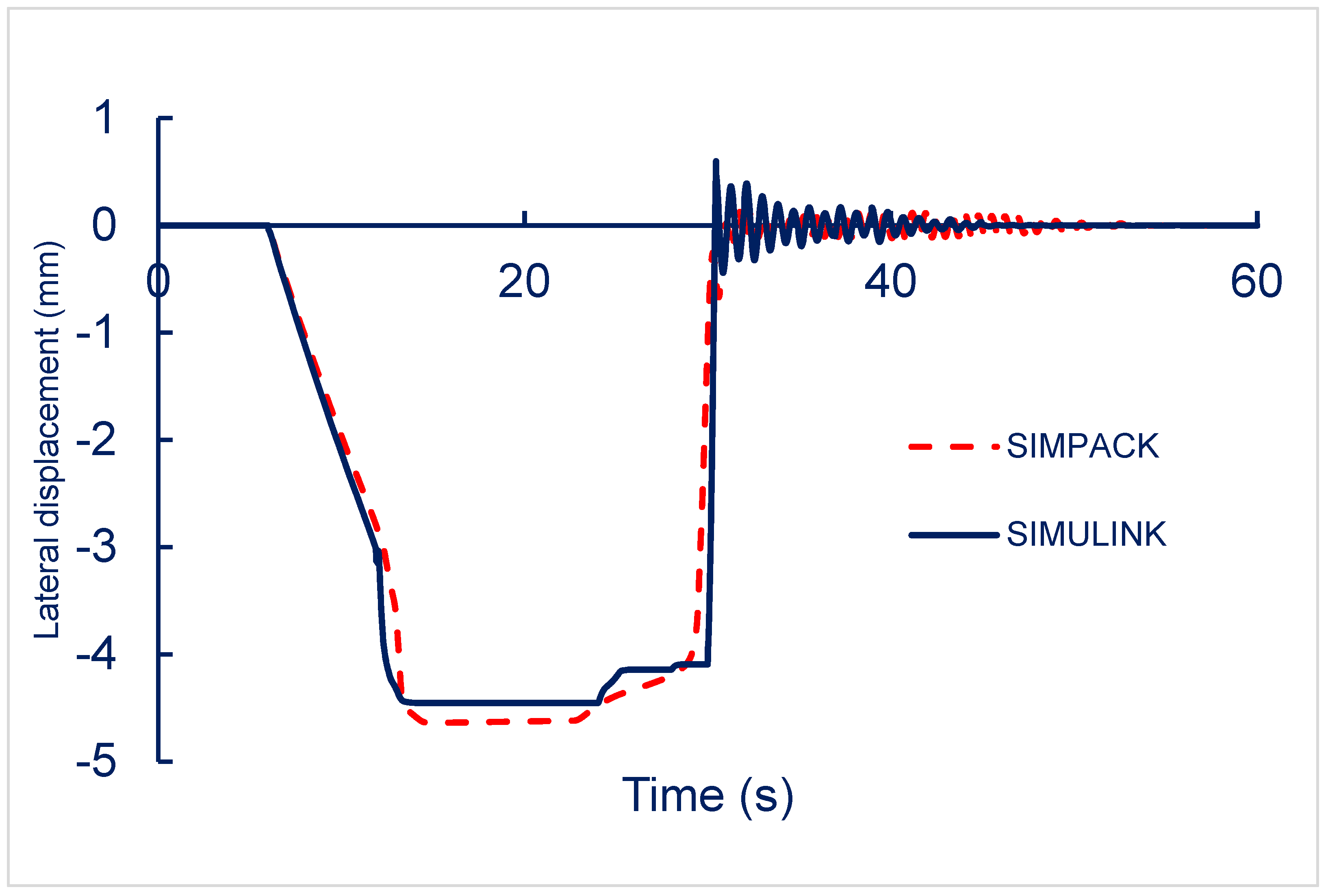
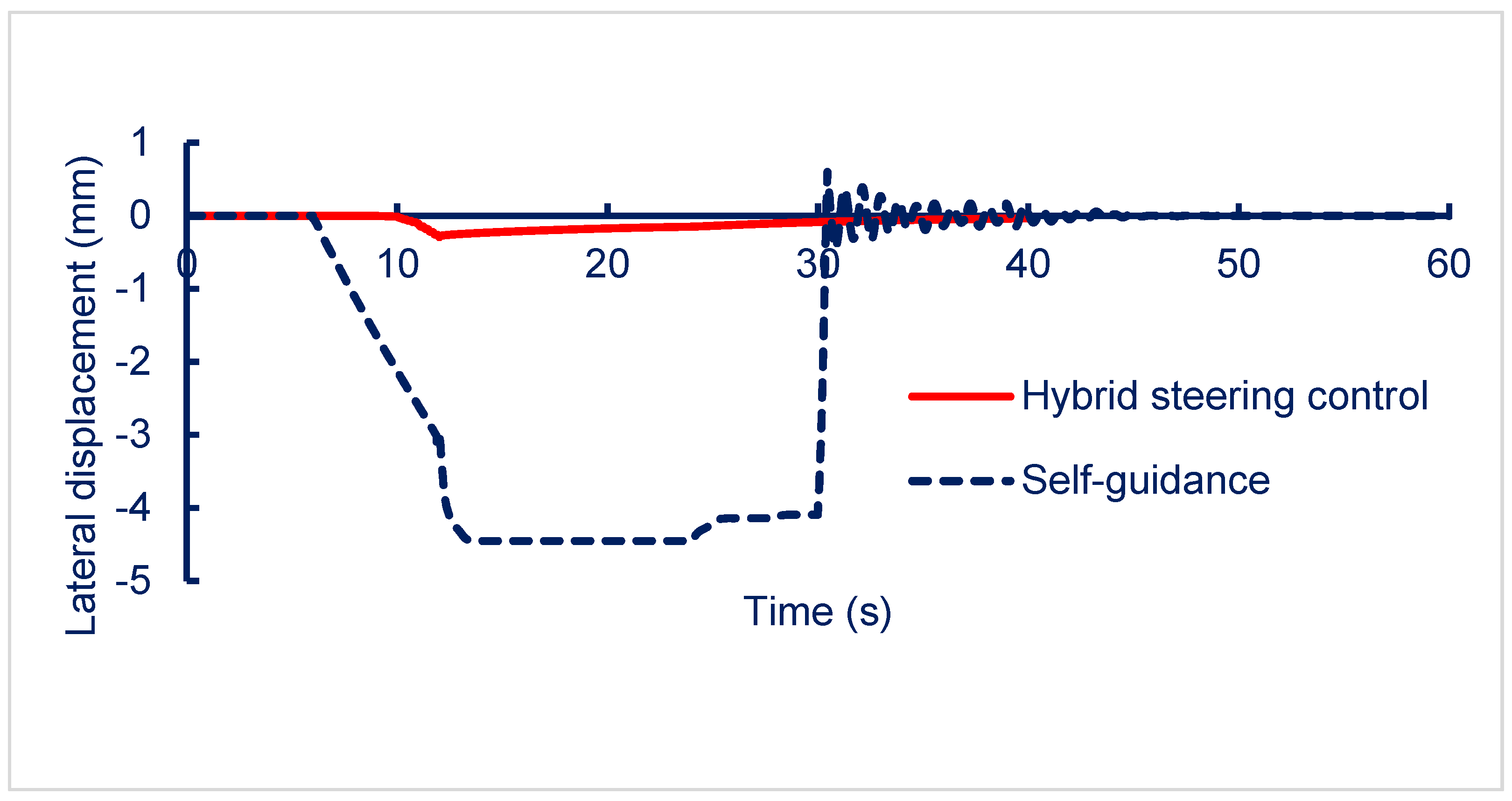
3.2. Running on a Right-Corner Track
The vehicle’s self-steering ability during cornering was simulated with reference to the MRT track in Taipei, Taiwan, with a 200 m radius right turn. The turn radius of the track changed gradually and then increased to facilitate smooth passage. The straight track (STR) refers to the section of the track leading into the curve. The clothoid transition (CLO1) connected the straight track to the curve, gradually reducing the turn radius to the smallest value of 200 m. The vehicle then navigated the circular curve (CIR), where the radius remained constant at 200 m. Afterward, the turn radius increased gradually along the second clothoid transition (CLO2), eventually returning to another straight-track segment.
Figure 8 illustrates the lateral displacement of the vehicle center when turning right. SIMULINK and SIMPACK simulation results indicated that the distance between the horizontal position of the vehicle center and the center of the track increased when the vehicle was running on the CLO1 segment and peaked at 4.5 mm when the radius of the track was decreasing. These figures remained unchanged when the vehicle was operated on a CIR segment with a constant track radius. When the vehicle was running on the CLO2 stretch, the lateral position of the vehicle center substantially reduced before returning to a stable position after cornering.
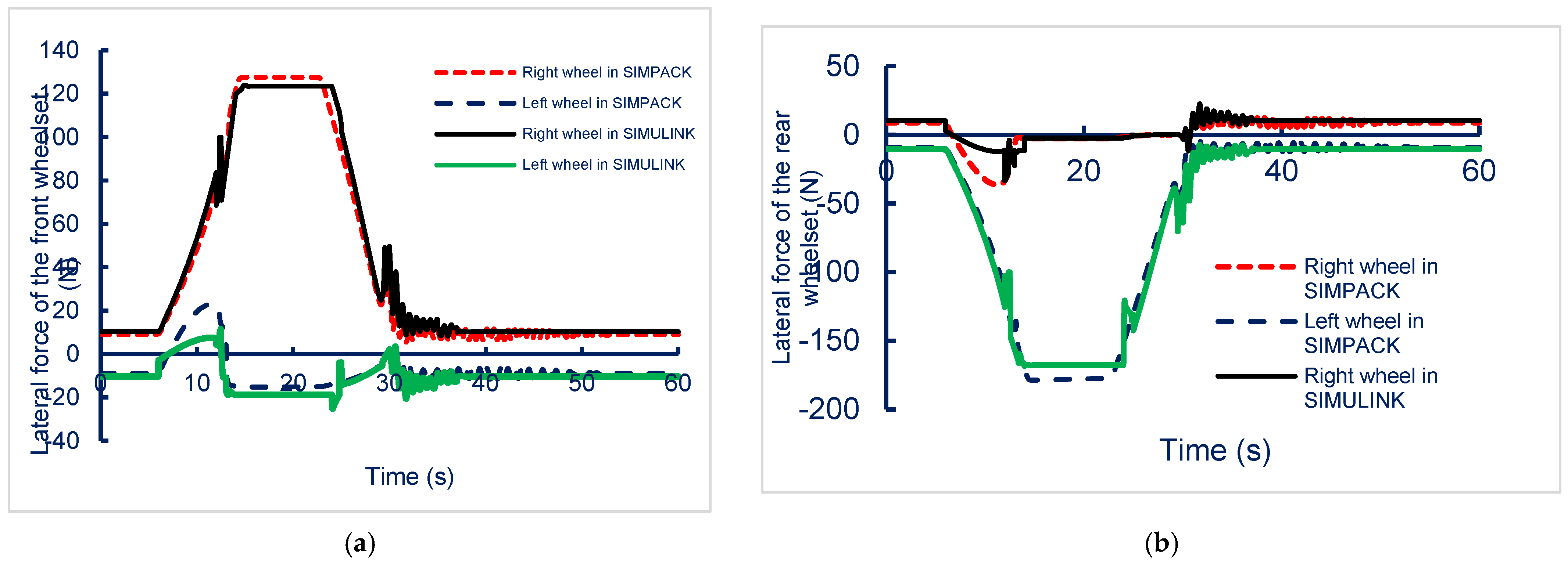
Figure 9 illustrates the lateral forces acting on the front and rear wheelsets while navigating a right-turning track in SIMPACK and SIMULINK simulations. In
Figure 9a, the right wheel of the front wheelset experiences a peak lateral force of approximately 125 N, while the left wheel remains near zero. In
Figure 9b, the left wheel of the rear wheelset shows a peak force of about −175 N, indicating significant asymmetry in the lateral force distribution during cornering. Simulation results indicated that the vehicle center did not maintain a balanced position during cornering; this can affect the test results of inspection systems. Thus, the proposed steering control system was deemed necessary to improve the inspection capabilities of the micro-autonomous vehicle.
Simulation results for the straight and right-corner track indicated that the lateral position of the vehicle center and the lateral forces acting on the left and right wheels differed by less than 10%. Thus, the horizontal dynamics model created using SIMULINK was considered appropriate for further simulations of the vehicle’s steering system control.
5. Conclusions
The hybrid steering control system of the new micro-autonomous railway inspection vehicle was developed with the goal of substantially enhancing test performance and operational stability. In the SIMPACK and SIMULINK models, the lateral dynamics of the vehicle were simulated with consideration of the wheel–rail contact and self-guiding mechanisms. The results of this simulation confirmed the need for a robust steering control system to ensure proper vehicle functionality. The hybrid steering control system, which integrates a fuzzy logic controller with the self-guiding capability of the wheelset, demonstrated the ability to maintain the vehicle’s equilibrium at the centerline of the track during operation. Simulation results showed that the system effectively reduces lateral deviations, keeping the vehicle stable with deviations below 10%, even under varying working conditions. This performance highlights the system’s ability to leverage natural self-guiding forces while enhancing response and stability through active control.
This study introduced a novel set of vehicle motion equations that integrate the self-guidance properties of the wheelset with an adaptive fuzzy logic controller. Simulations and comparative analysis confirmed that our approach improves positioning accuracy, reduces computational time, and enhances dynamic stability. These advancements contribute to the development of more efficient and precise autonomous railway inspection vehicles. Future work will focus on experimental validation and further optimization for diverse operational conditions.
In future work, we plan to apply and experiment with this hybrid steering control system to a real model of the new micro-autonomous railway inspection vehicle to analyze and evaluate the system’s energy efficiency and performance and improve its control. While the hybrid steering control system enhances lateral stability, several challenges remain for real-world implementation. High computational demands may affect onboard processing efficiency, while rail contamination, such as dust or oil, can alter wheel–rail adhesion, impacting control accuracy. Additionally, prolonged wheel wear may affect self-steering characteristics. Future work will focus on optimizing control algorithms, reducing computational load, and implementing adaptive tuning strategies to maintain performance under varying operational conditions.


