1. Introduction
Ultra-stable lasers are an essential instrument in the fields of time-frequency standards, precision measurements, and quantum optics [
1,
2,
3,
4,
5,
6]. With the development of space technology, the application of ultra-stable lasers has expanded from ground-based experiments to space science missions [
7,
8,
9,
10]. Ultra-stable laser systems on space platforms (space stations and satellites) have shown wide application prospects in space science experiments. For example, the Laser Interferometer Space Antenna (LISA) mission will use the ultra-stable laser as interferometric light source to build millions of miles of laser interferometers in space [
11]. The Next Generation Gravity Mission (NGGM), based on ultra-stable lasers, will provide enhanced spatial and temporal resolution time-varying gravity field measurements [
12], etc.
Fabry-Pérot (FP) cavities are the core components of ultra-stable lasers. Frequency stability of an ultra-stable laser depends on the stability of the FP cavity optical length. Compared to the laboratory ultra-stable laser, the space-borne ultra-stable laser is exposed to harsher environments, such as mechanical vibrations during rocket launch. Mechanical vibrations or shocks may cause position shift of the FP cavity, leading to a decrease in the performance of the ultra-stable laser. Therefore, improvement of the FP cavity support is a key technology in the space ultra-stable laser. Research efforts have been devoted by many research groups to address this technology [
13,
14,
15]. For example, in 2020, Häfner, S. et al. achieved transportability of a 12 cm-long FP cavity by implementing a rigid, compact, and vibration insensitive mounting [
16]. In 2020, Chen, X. et al. mounted a FP cavity on a cubic spacer, which is rigidly mounted for both low sensitivity to environmental vibration and ability for transportation [
17]. In 2021, Xu, G. et al. reported a transportable ultra-stable laser at 1550 nm, and vibration tests were conducted including 100 km actual road transportation and 34 min continuous vibration [
18]. In 2024, Cole, G.D. et al. developed a transportable laser frequency stabilization system [
19], etc. In our previous works, a reliable, robust and stable method for fixing 100 mm cubic FP cavity was used to allow the cavity to pass the aerospace mechanical tests [
20]. The number of support points was increased and the contact surface was enlarged to provide a reinforced-support for the cubic FP cavity. The reinforced-support method provides another choice of support method for space applications compared to the traditional four-point support method. However, in the reinforced-support design, the increase in contact surfaces and constraint points may lead to unforeseen thermo-mechanical and vibrational effects. Thus, it is necessary to investigate the effects of this reinforced-support method on the cavity performance.
In this paper, the performance of a 100 mm cubic FP cavity with reinforced-support was analyzed. Firstly, the FP cavity with reinforced-support was modeled. Vibration sensitivity and zero-expansion temperature of the FP cavity were analyzed by the finite element analysis (FEA). Subsequently, vibration sensitivity and zero expansion temperature of the FP cavity were tested experimentally. Through compared to the traditional four-point support FP cavity, the reinforced-support FP cavity has the same vibration sensitivity. This reinforced-support FP cavity is suitable to ultra-stable lasers of 10−15 or even 10−16 magnitude, and may expand the application of ultra-stable lasers in transportable or space.
2. Simulation Analysis of the Cubic FP Cavity with Reinforced Support
The FP cavity is the reference unit of the ultra-stable laser. Since being proposed by the National Physical Laboratory (NPL), the cubic FP cavity has presented potential for transportable and space applications [
21]. The reinforced-support cubic FP cavity structure was designed in our previous work, which successfully passed the aerospace-grade mechanical vibration test [
20]. To clearly understand the thermal-mechanical characteristics of the reinforced-support cavity (mainly including vibration sensitivity and zero-expansion temperature), this cavity was first modeled and analyzed.
2.1. Simulation Modelling
In the analysis process, a 100 mm cubic FP cavity with reinforced-support was modelled firstly. The simulation models of the FP cavity are shown in
Figure 1. In
Figure 1a, the cube in the center of the structure was the FP cavity, and the outer skeletonized frame was the bracket. There were eight support screws on the bracket to fix the FP cavity. ULE (Ultra-Low Expansion) glass cavities and fused silica mirrors are the common materials for room-temperature FP cavities [
22,
23,
24]. Polyimide is a commonly used resin engineering material. Materials such as Teflon and PEEK have also been used by researchers in previous studies [
25]. In the simulation, a cylindrical shim made of polyimide was used where the screw contacts the FP cavity. The material of the FP cavity was set to be ULE glass and the mirrors were set to be fused silica. The compensation rings on the mirrors were also set to ULE glass. The support bracket and screws were set as titanium alloy. The simulation parameters for vibration sensitivity are shown in
Table 1. When analyzing the vibration sensitivity, the support brackets and screws were removed to simplify the analysis process. When analyzing the zero-expansion temperature of the FP cavity, the complete structure as shown in
Figure 1a was used.
2.2. Vibration Sensitivity Analysis
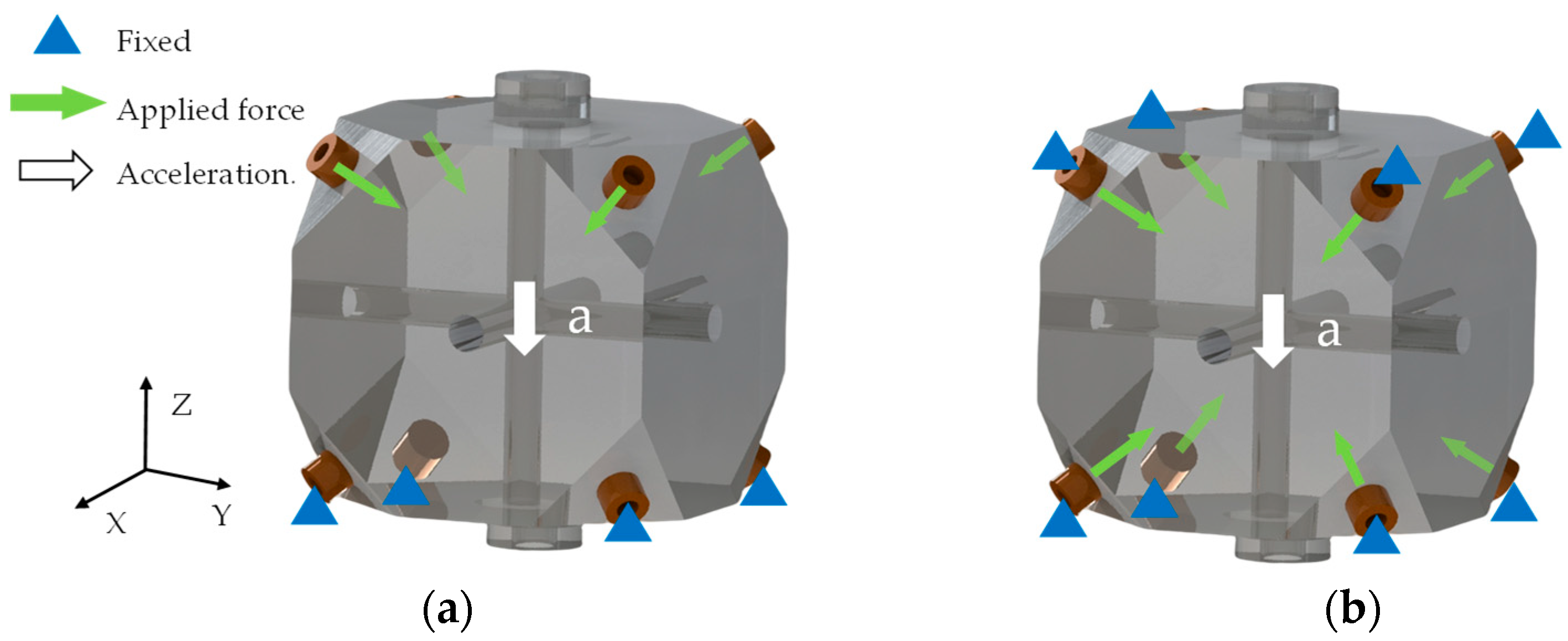
Constraint settings for calculating vibration sensitivity of the FP cavity are shown in
Figure 2. Two different constraints were taken to analyze vibration sensitivity of the FP cavity.
Figure 2a shows the FP cavity constraint setup based on the analytical method reported in the literature [
26] for four point-supported FP cavities. The bottom four polyimide shims were set to be fixed when the acceleration was in the -Z direction. Since the FP cavity needed to apply a preload force during assembly, the top four polyimide shims were set to applied force.
Figure 2b shows another constraint method. Unlike the previous method, the planes of the Polyimide shims in contact with the FP cavity were set to applied force, and on the other sides of the Polyimide shims were set to fixed. Frictional contacts were set between the Polyimide shims and the FP cavity in the second method. The amount of deformation at the center of the FP cavity mirrors was used to calculate the vibration sensitivity. Both constraint methods were designed to simulate a realistic situation. For example, considering that the bottom four shims mainly play the role of fixed support when the acceleration is in the -Z direction, the first constraint method is adopted for the analysis. The second method takes into account the fixation and preload applied to the shims during assembly.
Based on the first constraint setting method, vibration sensitivity of the FP cavity was calculated for different applied forces (50 N, 70 N, 100 N, and 150 N) in the X, Y, and Z directions. The results of the analysis are shown in
Figure 3a. Vibration sensitivity of the FP cavity in the three directions is consistent under different applied forces. This demonstrates that the FP cavity is force insensitivity with the reinforced support. Meanwhile, the FP cavity presents vibration insensitivity in the Z direction. Vibration sensitivity of the FP cavity is consistent in the X, Y direction. With an applied force of 70 N, the vibration sensitivities in the Z, X, and Y directions are 0, −9.69 × 10
−11/g, and −9.57 × 10
−11/g, respectively.
Figure 3b shows the results of vibration sensitivity analysis based on the second constraint setting method. With an applied force of 70 N, vibration sensitivities of the FP cavity in the Z, X, and Y directions are 1.2 × 10
−10/g, −1.6 × 10
−12/g, and −1 × 10
−12/g, respectively. In the X, Y direction, the FP cavity also presents force insensitivity. In the Z-direction, the second constraint method presents force insensitivity at 70 N, 100 N, and 150 N. Vibration sensitivity of the FP cavity changes by −2 × 10
−11/g when the applied force is 50 N.
Regarding the two different constraint methods, FP cavity vibration sensitivity in both X and Y directions is below −1 × 10⁻¹⁰/g and remains force insensitive in the range of 50–150 N. This indicates the consistency of the vibration sensitivity of the FP cavity in X, Y directions for both constraints setting methods. The two methods have different results in the Z direction. With the first constraint setting method, the FP cavity is vibration insensitive in the Z direction. Whereas, with the second constraint setting method, vibration sensitivity of the FP cavity is about 10−10/g magnitude. In addition, vibration sensitivity of the FP cavity is below 1.5 × 10⁻¹⁰/g in all three directions for both constraints setting methods. The effect of vibration on the stability for the FP cavity can still be below 1.5 × 10⁻¹⁶ in an environment where micro-vibration is on the order of 1 × 10⁻⁶ g. For a 100 mm ULE cavity, the thermal noise limitation is on the order of 10−16. Therefore, the vibration sensitivity of the reinforced-support FP cavity is still suitable to ultra-stable lasers of 10−15 or even 10−16 magnitude, according to the simulation results.
2.3. Zero-Expansion Temperature Analysis
According to the description of the literature [
20], the reinforced-support FP cavity used silicone rubber to bond the screws to the FP cavity for enhanced fixing. When the FP cavity contacted the support screws and silicone rubber, a combined structure was formed. CTE (coefficient of thermal expansion) of the FP cavity could be affected by these contact materials. Therefore, zero-expansion temperature of the FP cavity needed to be analyzed.
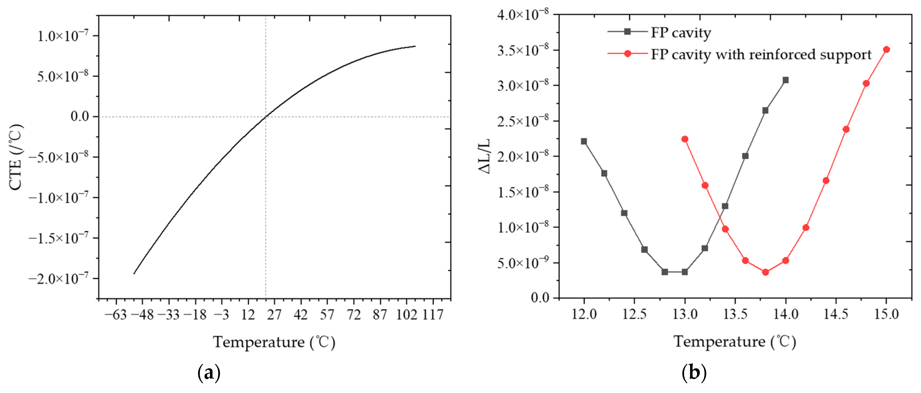
In the simulation, CTE of the ULE glass is shown in
Figure 4a. The ULE glass has a zero-expansion temperature at 22 °C. Results of the zero-expansion temperature analysis of the FP cavity are shown in
Figure 4b. It can be seen from the figure that the value of deformation in the center of the FP cavity varies with temperature. The zero-expansion temperature of the FP cavity is 12.8 °C. Compared to the ULE glass zero-expansion temperature of 22 °C, the zero-temperature of the FP cavity changed by 9.2 °C. This change is caused by fused silica mirrors, which has been reported in the literature [
6]. After using the reinforced-support structure, the zero-expansion temperature of the FP cavity increased from 12.8 °C to 13.8 °C. This suggests that the FP cavity is affected by the reinforced-support structure about 1 °C.
Zero-expansion temperature simulation results demonstrate that although the bracket, screws, and FP cavity formed a combined structure, the structure has limited effect on the zero-expansion temperature of the FP cavity. According to our analysis, for the FP cavity, the laser is transmitted between two fused silica mirrors to form a resonance. This means that the optical length of the FP cavity is equal to the distance between the two fused silica mirrors. The thermal deformation of the fused silica mirrors will directly affect the optical length of the FP cavity. Whereas the support bracket, screws, etc. do not directly contribute to optical length of the FP cavity. The thermal deformation of these structures affects the FP cavity through the action of forces. For example, when a temperature change causes the support structure and FP cavity to expand, if the expansion of the FP cavity is greater than that of the support structure, the support structure will produce a pressure on the FP cavity. This pressure applied to the FP cavity influences the optical length of the FP cavity. Since the FP cavity cube material is ULE glass, which has a Young’s modulus of about 67.6 GPa, the effect of the pressure on the FP cavity needs to be divided by the Young’s modulus.
To verify the above analysis, the stress in the FP cavity at different temperatures was also analyzed during the simulation. The results of the analysis are shown in
Figure 5. The stress on the FP cavity increases with the increase of temperature, which proves that the thermal deformation of the support structure affects the FP cavity by force. In addition, not all support structures have a limited effect on FP cavities. With the increase of contact surface between the FP cavity and the outer support structure, the thermal deformation of the outer support structure will also have an increased effect on the FP cavity.
3. Experiments
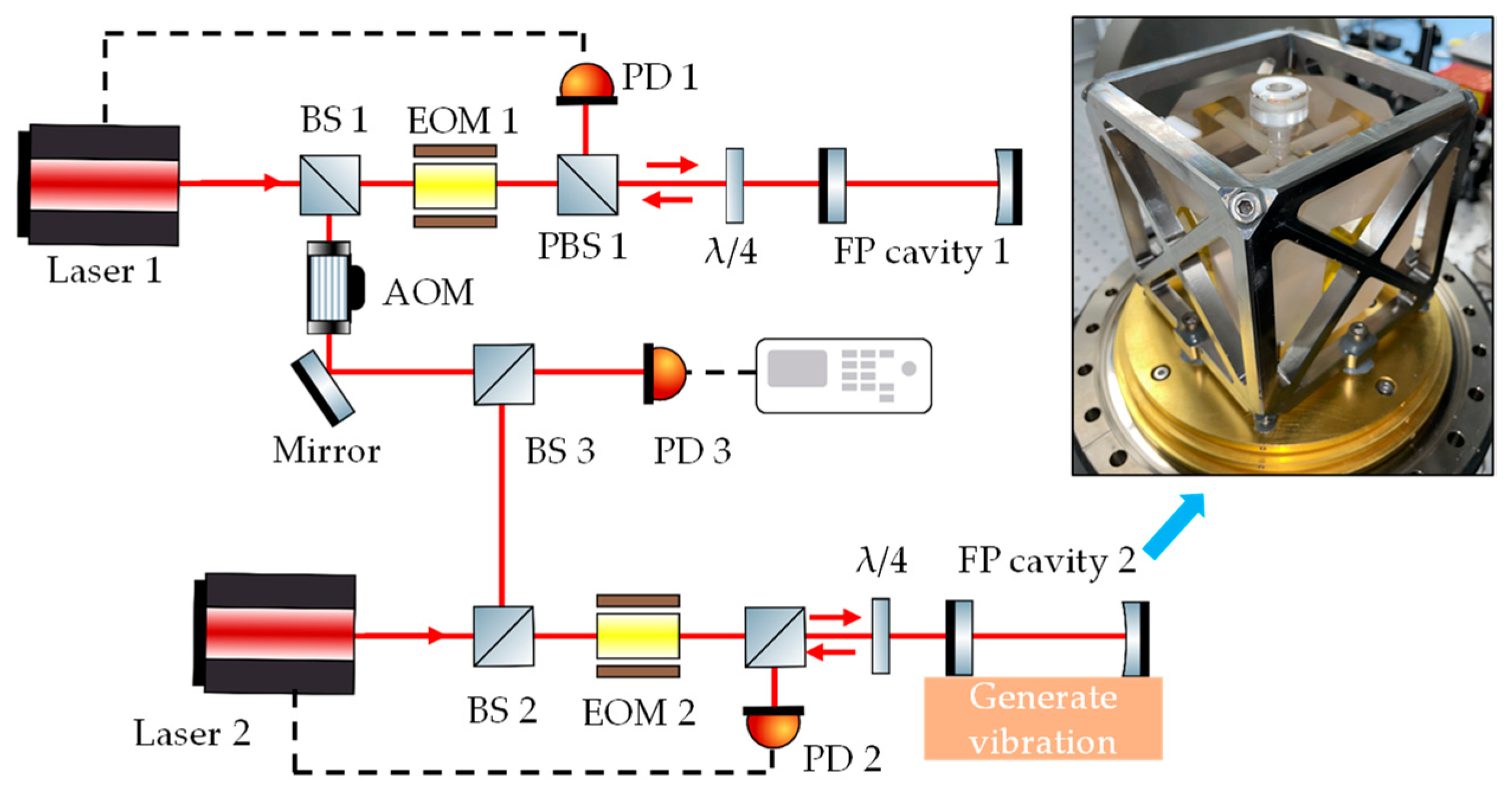
Vibration sensitivity of the reinforced-support FP cavity was tested using two ultra-stable lasers. Both ultra-stable lasers were frequency locked by the PDH method. One of the ultra-stable lasers had a reinforced-support FP cavity. The reinforced support FP cavity was placed on a vibration table. After an acceleration was generated by the vibration table, the vibration sensitivity of the FP cavity was measured by testing the beat frequency variation of the two lasers. The schematic diagram of the vibration sensitivity test is shown in
Figure 6. Firstly, the laser 1 was locked to the FP cavity 1. The laser from the laser 1 passed through BS1, EOM1, PBS1 and λ/4 and entered the FP cavity 1. The laser reflected by the FP cavity 1 was collected by PD1 for PDH frequency locking. Secondly, the laser 2 was locked to the FP cavity 2 (reinforced-support FP cavity). The laser locking optical path was same as laser 1. Subsequently, the laser 1 and laser 2 were frequency beat after frequency locking. Subsequently, the lasers from laser 1 and laser 2 passed through BS3 for frequency beating. The frequency-beat signals were collected by PD3 (FPD310 detector from Menlo Systems, Planegg, Germany) and analyzed using a frequency counter (FCA3100 from Tektronix, Beaverton, OR, USA) and a spectrum analyzer (FCA3100 from Tektronix, Beaverton, OR, USA). The FP cavity 2 was placed on a vibration table (Table Stable’s TS-150), and acceleration was applied by the vibration table. Finally, different accelerations were applied to the FP cavity 2 to measure the beat frequency changes. Vibration sensitivity of the FP cavity was calculated from the amount of acceleration and frequency variations.
The zero-expansion temperature test of the FP cavity was then carried out. After changing the operating temperature of FP cavity 2, the FP cavity 2 would thermally deform, resulting in the beat frequency of the two lasers being changed. The curve of the beat frequencies variation with temperatures could be obtained by testing the beat frequencies at different temperatures. The zero-expansion temperature of FP cavity 2 was obtained from this curve. The specific method was: firstly, The FP cavity 2 operating temperature was changed. When the FP cavity 2 temperature stabilized, the beat frequency was measured. The operating temperatures of FP cavity 2 were set to 25 °C, 27.5 °C, 28 °C, 30 °C, and 30.5 °C, respectively. The beat frequency results at these temperatures were recorded separately. Then, the variation curve of beat frequencies at different operating temperatures was plotted. According to this curve, the temperature at which the beat frequency reached the minimum value was derived, and this temperature was the zero-expansion temperature of the FP cavity 2.
4. Results and Discussion
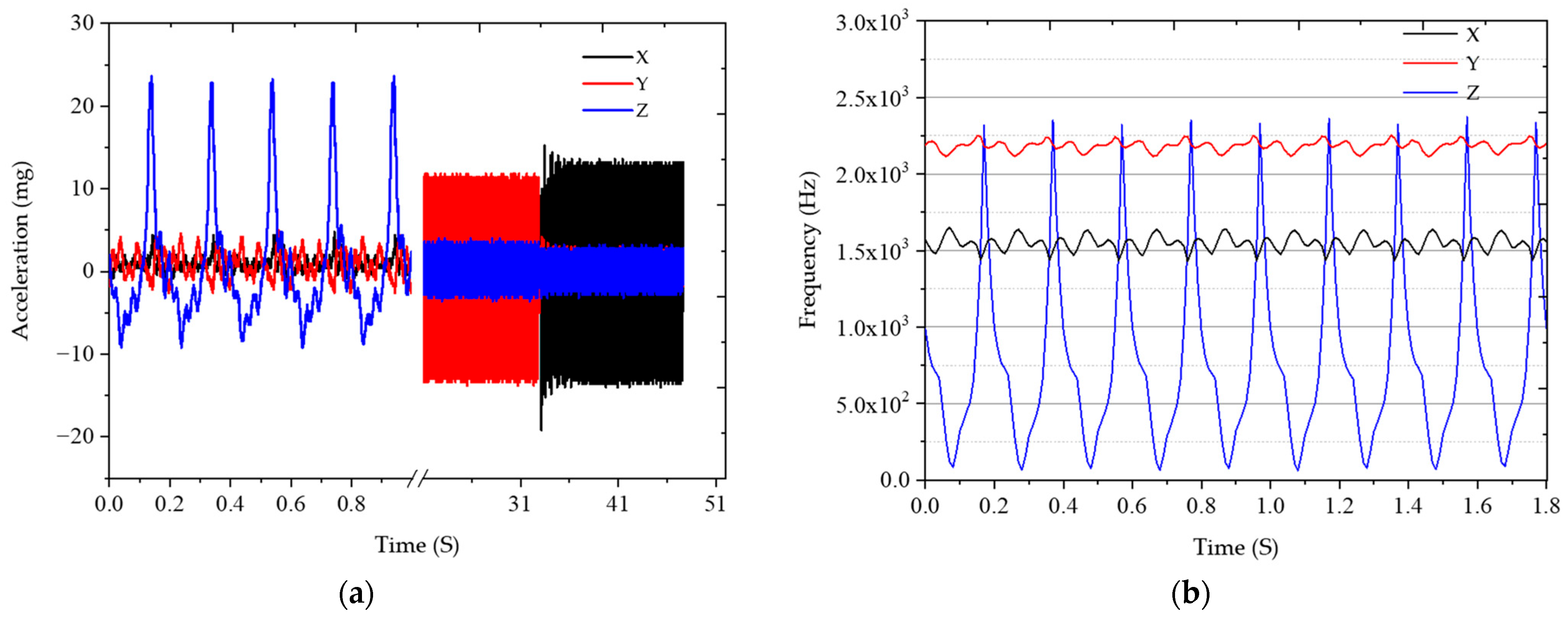
In testing the vibration sensitivity, frequency and acceleration variations of the FP cavity are shown in
Figure 7.
Figure 7a shows the acceleration of the FP cavity in the Z, Y, and X directions sequentially. For example, in the detail area of the 0–1 s display, an acceleration of about 25 mg was applied in the Z direction, and a micro-vibration of 5 mg still occurred in the other two directions.
Figure 7b shows the frequency variation caused by the change in acceleration. Frequency variation attributed to acceleration in the Z direction (direction of the optical axis of the FP cavity) is higher than both the X and Y directions. The vibration sensitivity of the FP cavity was calculated according to the method of literature [
26]. The vibration sensitivities of the FP cavity in the Z, X, and Y directions are calculated to be 1.73 × 10
−10/g, −2.09 × 10
−11/g, and −2.13 × 10
−11/g, respectively.
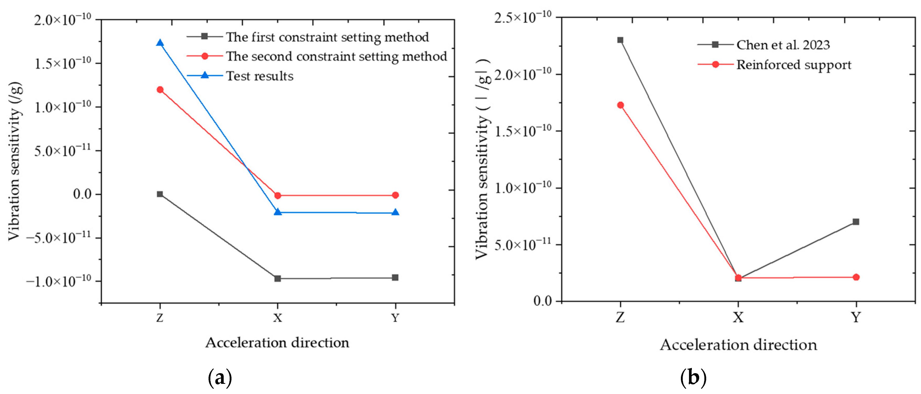
Experimental results are compared with the simulation results as shown in
Figure 8a. The experimental results agree with the trend of the simulation results of both methods. However, compared to the first constraint setting method in the simulation, the experimental results are different in the Z direction. The vibration sensitivity in the simulation presents 0 in the Z direction, while the experimental results indicate the vibration sensitivity is 1.73 × 10
−10/g. The vibration sensitivities of the FP cavity in the X and Y directions are comparable to the simulation results. The simulation and experimental results are in the order of 10
−11/g. Compared to the second constraint setting method in the simulation, the experimental results agree with the simulation results in the Z direction. In the X and Y directions, the simulations are in the order of 10
−12/g, which is different from the experimental results.
According to our analysis, there are several possible reasons for the difference between the simulation and experimental results. Firstly, the parameters of the simulated materials may differ from the actual materials. For example, differences in Young’s modulus and Poisson’s ratio can lead to the difference between the simulation and experimental results. the Young’s modulus of the ULE used in the simulation is 69.6 GPa (data from Corning’s Model 7973 ULE glass), and different batches of material may differ from this value in practice. Therefore, the results of the simulation can provide certain reference for the vibration sensitivity analysis. Secondly, the existence of machining and mounting errors makes the FP cavity size deviate from the theoretical design. These deviations lead to inconsistency between experimental and simulation results. For example, the preload on the contact surface between the polyimide shim and the FP cavity may be unbalanced due to the angle of the screw threads; Owing to machining errors, the position of the support points is offset from the design position, etc. In addition, the test results of vibration sensitivity also have errors. In any case, the trends of the simulation and experimental results are in line. The experimental results show that the maximum value of the vibration sensitivity of the FP cavity is 10−10/g magnitude in the Z direction, which is in line with the simulation results.
Vibration sensitivity of the reinforced-support FP cavity and the four-point support type reported in the literature [
26] were compared. The comparison results are shown in
Figure 8b and
Table 2. After taking the absolute value of the vibration sensitivity of the reinforced-support results (regardless of the direction of the FP cavity deformation), the FP cavity of the reinforced-support is consistent with the vibration sensitivity of four-point support reported in the literature. In the Z, X and Y directions, the FP cavity vibration sensitivities reported in the literature [
26] are 2.3 × 10
−10/g, 2 × 10
−11/g, and 7 × 10
−11/g, respectively. The measured vibration sensitivities for the reinforced-support are 1.73 × 10
−10/g, 2.09 × 10
−11/g, and 2.13 × 10
−11/g, respectively. The FP cavity vibration sensitivities for both support methods are below 2.5 × 10
−10/g in the Z direction and below 1 × 10
−10/g in the X and Y directions. This indicates that the reinforced-support FP cavity can achieve the same level of vibration sensitivity as the four-point support FP cavity.
In addition to vibration sensitivity, zero-expansion temperature of the reinforced-support FP cavity was also tested.
Figure 9 shows the measurement results of zero-expansion temperature. The fitted curves were plotted according to the method of literature [
6]. The fitting result shows that the zero-expansion temperature of the reinforced-support FP cavity is about 29.5 °C. However, the zero-expansion temperatures of the FP cavity with and without reinforced-support are not compared because accurate zero-expansion temperature data is not obtained when purchased. The zero-expansion temperature of ULE glass is in the range of 30 ± 5 °C according to the information provided by the manufacturer. The experimental result of the zero-expansion temperature of the FP cavity is in line with this range. Therefore, according to the experimental and simulation results for zero-expansion temperature, although the exact value of the zero-expansion temperature being affected is not known, the reinforced-support method has limited effect on the zero-expansion temperature of the FP cavity.
Although the reinforced-support FP cavity has the same level of vibration sensitivity as the four-point support FP cavity, several obvious disadvantages exist. Compared to the four-point support method, the number of support points is increased from four to eight. The increase in the number of support points will result in assembly stresses. The presence of assembly stresses will affect the length stability of the FP cavity. In addition, the increase in the number of support points and the increase in support area will affect the heat transfer between the support structure and the FP cavity. The temperature transfer from the support structure to the FP cavity will be faster, which will also affect the stability of the cavity length.
5. Conclusions
Vibration sensitivity and zero-expansion temperature of a 100 mm cubic reinforced-support FP cavity were analyzed. Firstly, vibration sensitivity of the FP cavity was modeled and simulated. To simulate the real situation of the FP cavity, two different constraints were used for the analysis. The analysis results of both constraint methods show that the vibration sensitivity of the FP cavity is lower than 1.5 × 10⁻¹⁰/g. Secondly, zero-expansion temperature of the FP cavity was simulated. The analysis results show that the zero-expansion temperature of the FP cavity with reinforced support is affected by about 1 °C compared to the zero-expansion temperature of the FP cavity itself.
Vibration sensitivity and zero-expansion point temperature of the FP cavity were tested experimentally. The experimental results show that vibration sensitivities of the reinforced-support FP cavities are 1.73 × 10⁻¹⁰/g, 2.09 × 10⁻¹¹/g, and 2.13 × 10⁻¹¹/g in the Z, X and Y directions. This is consistent with the results of the simulation. Compared with the four-point support FP cavity, the reinforced-support FP cavity has a similar vibration sensitivity. The zero-expansion temperature of the reinforced-supported FP cavity is about 29.5 °C. According to the experimental and simulation results for zero-expansion temperature, the reinforced-support method has limited effect on the zero-expansion temperature of the FP cavity.
The reinforced-support FP cavity offers performance consistent with a four-point support. The reinforced-support FP cavity can remain stable in the environment of mechanical vibrations such as transportation or rocket launches. Therefore, this reinforced-support may expand the application of ultra-stable lasers with cubic FP cavity in transportable or space applications.


