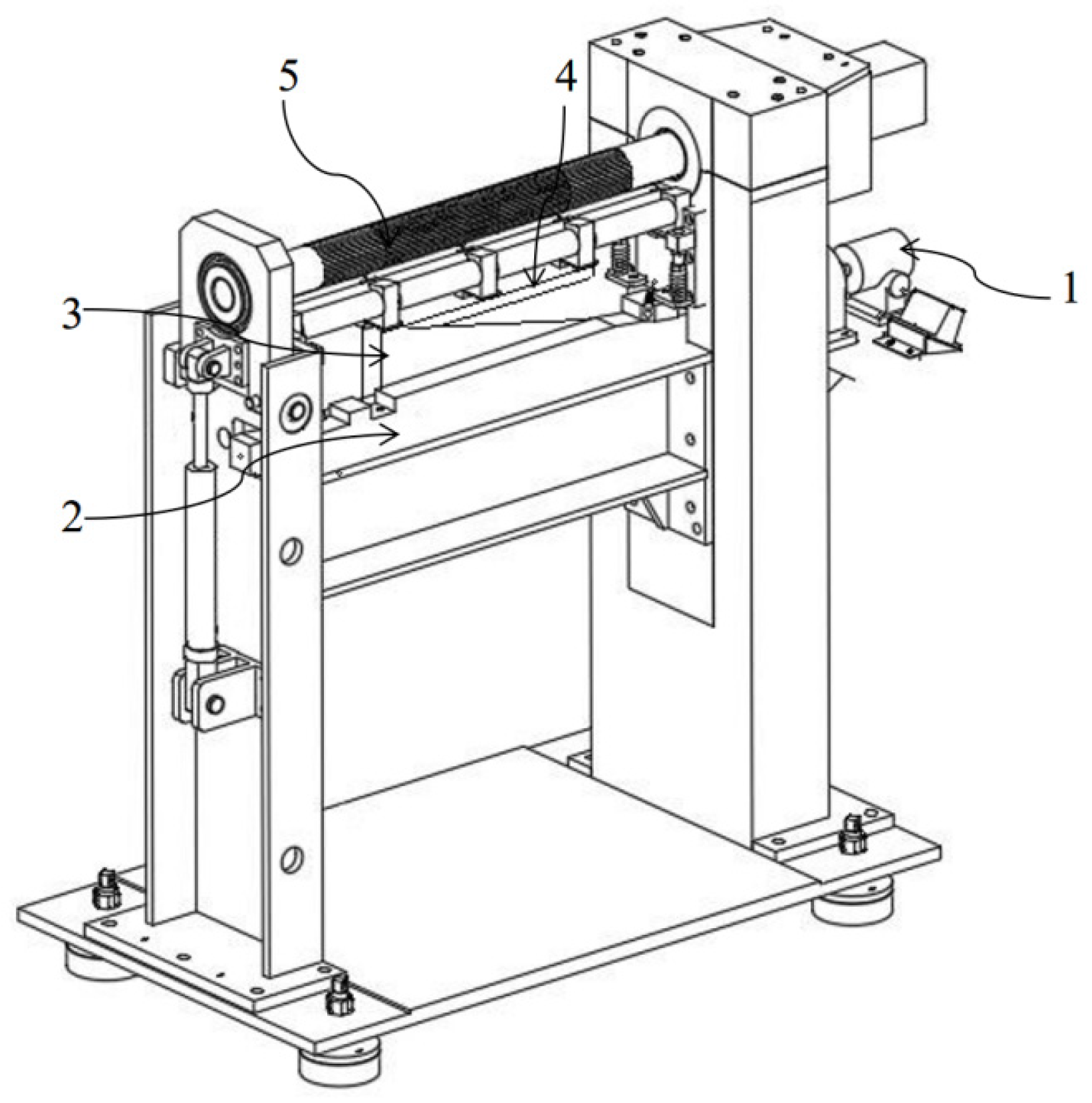
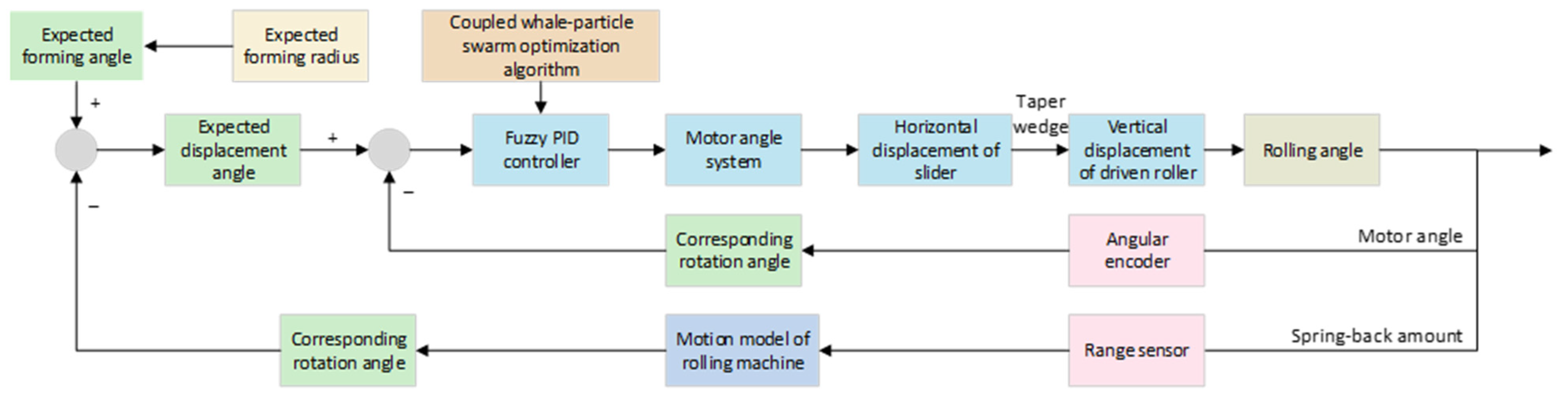
Within a circular rolling cycle, the desired motor rotation angle corresponding to the desired forming radius is input into the improved fuzzy PID controller. The horizontal displacement of the slider is achieved by controlling the motor rotation angle. The wedge then transforms the horizontal displacement of the slider into the vertical displacement of the driven roll, thereby altering the gap between the driving roll and the driven roll to attain the desired rolling angle. To ensure the accuracy and precision of the circular rolling process, an angle encoder is employed to monitor the motor rotation angle and feed it back to the controller. Additionally, a distance sensor is utilized to monitor the springback amount. The fuzzy PID controller is optimized through the CWP algorithm proposed in this paper. This enables real-time reduction in the motor rotation angle difference and correction of the generated springback, ultimately achieving an accurate rolling angle.
3.2. CWP Algorithm Optimization
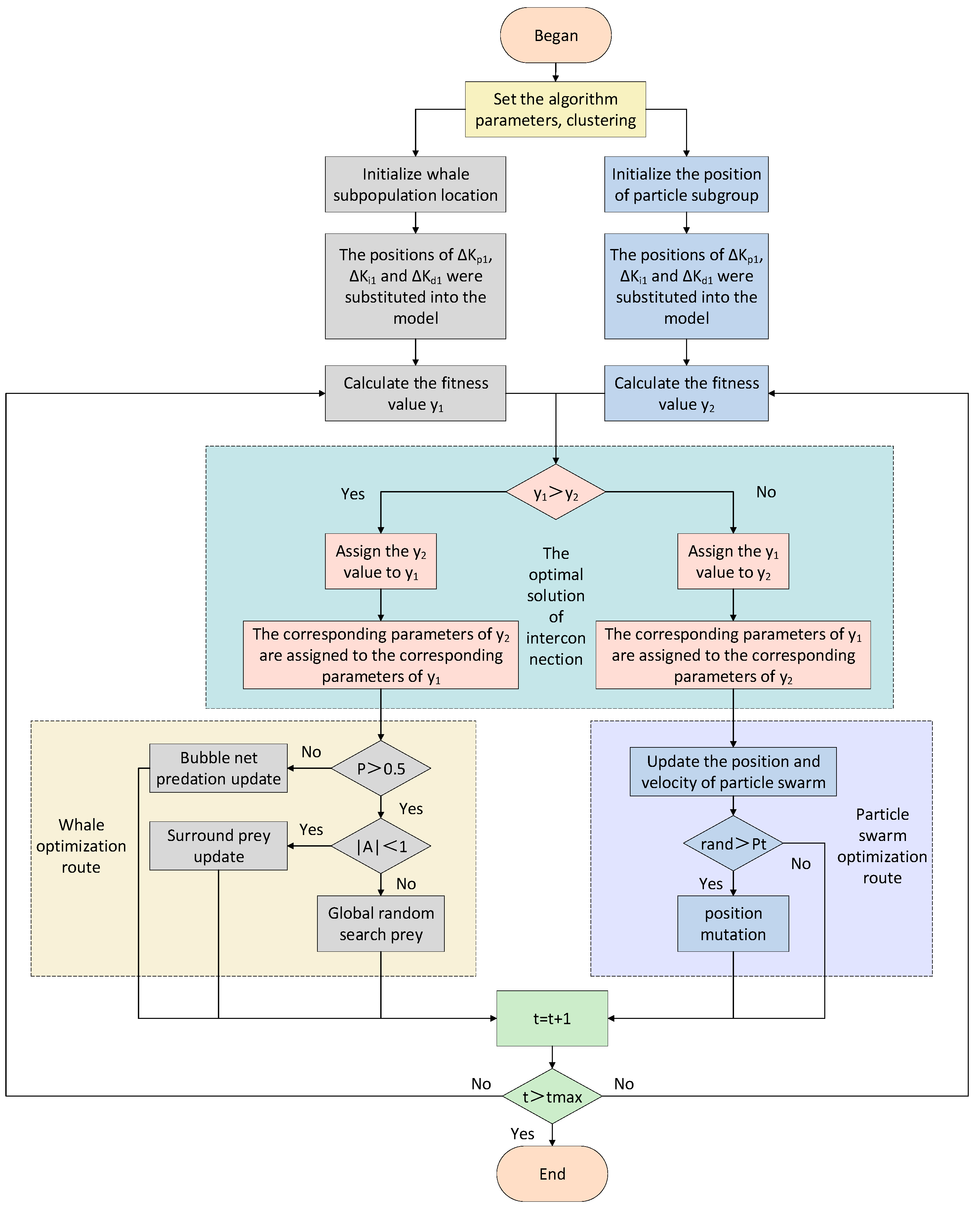
The coupled whale particle (CWP) algorithm integrates the rapid convergence property of the whale optimization algorithm (WOA) and the global search characteristic of the particle swarm optimization (PSO). It is designed to identify the optimal solution in a more expeditious and precise manner, thereby reducing the search space and curbing the consumption of computational resources. By minimizing the convergence deviation, it enhances the overall accuracy of the algorithm. Moreover, this algorithm can be applied to a diverse range of scenarios, circumventing the ineffectiveness of a single algorithm in certain specific situations. In the CWP algorithm, particles are partitioned into two independent search groups. The random parameters of these two groups are initialized, and their corresponding fitness values are computed. Subsequently, the smaller (i.e., superior) fitness value is extracted, which serves as the optimal solution for the current parameters. The optimal solutions are shared among the groups, and the next iteration commences. This process persists until the iteration terminates, at which point the optimal parameter results are output.
Figure 9 illustrates the overall procedure of the CWP algorithm for optimizing the parameters of the fuzzy PID controller.
Initially, prior to the commencement of the CWP algorithm, parameters are set, and particles are divided into two sub-populations as required. The positions of the two sub-populations are initialized. The integral of time-multiplied absolute error (ITAE) is adopted as the fitness value, which serves as the criterion for determining the optimization process. Assuming the simulation time is 1 s, the corresponding fitness value y is expressed by the following formula:
The positions of the two sub-populations are substituted into the model to calculate their respective fitness values. These two fitness values are then compared, and the smaller one is taken as the optimal solution for the current iteration. This optimal solution is assigned to the other sub-population. Meanwhile, the two sub-populations continue to search for the optimal solution along their own trajectories.
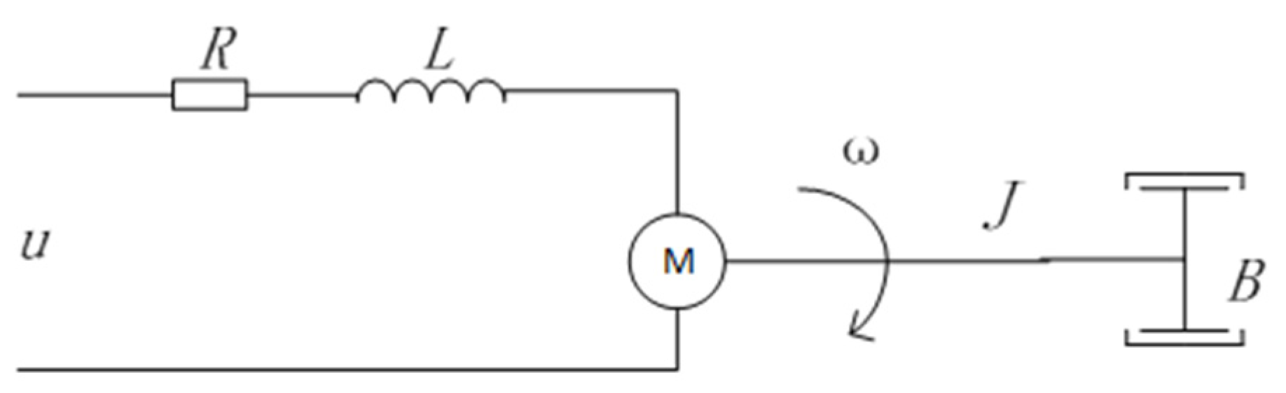
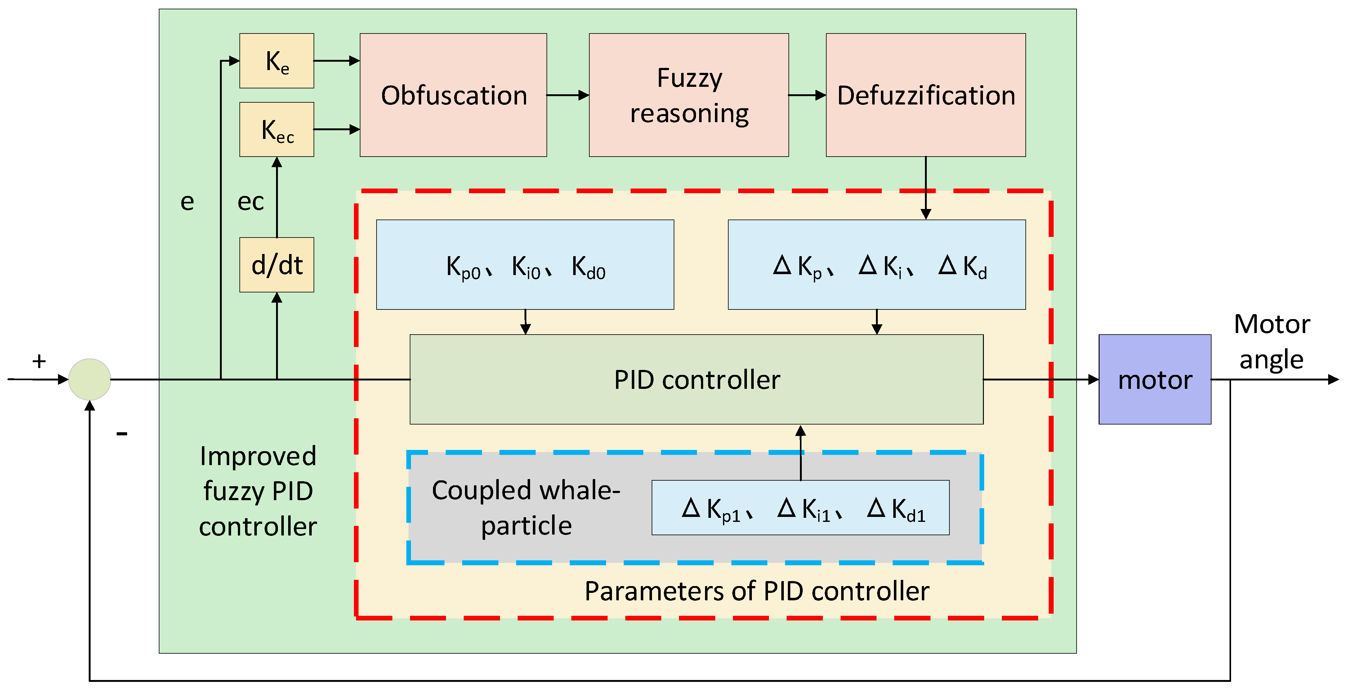
In the electromechanical control model, the system state variable x selects the current , the rotational speed , and the rotation angle of the motor (1), that is, . Combined with the display relationship between the position vector and the system state , the control of is achieved by adjusting to find the optimal state.
In the whale optimization route, it is necessary to determine whether the predation probability
p > 0.5. If not, the bubble-net predation update is carried out. The updated formula and the expressions of the relevant parameters are as follows [
25]:
If the predation probability is
p > 0.5, then it is necessary to further determine whether |A| < 1. If so, the update is carried out in accordance with the prey-encircling method. The updated formula and the expressions of the relevant parameters are as follows:
If not |A| < 1, the prey is updated according to the global random search. The formula is as follows:
Among them, and are coefficient vectors, and |A| represents the absolute value of the coefficient vector , which indicates the optimization speed and magnitude of encircling the prey and random search. is the position vector of the best solution obtained so far, is the current position vector, and is the updated position vector. Here, decreases from 2 to 0 during the iterative process, and are random vectors within the range of [0, 1], is a random number uniformly distributed in the range of [−1, 1], and is the position of the current random individual.
In the other optimization route, the positions and velocities of the sub-populations are first updated according to the particle swarm optimization approach [
26,
27]. The relevant expressions are as follows:
Next, it is necessary to determine whether the current random number rand is greater than the mutation probability Pt. If so, position mutation is carried out; if not, the next step is carried out. The mutation probability and the expressions for position mutation are as follows:
Here, represents the updated velocity of the particle swarm, is the updated position of the particle swarm, denotes the individual optimal extreme value, and represents the global optimal extreme value. is a random number. is the PSO inertia weight, is the maximum PSO inertia weight, and is the minimum PSO inertia weight. is the maximum value of the learning factor , is the minimum value of the learning factor , is the maximum value of the learning factor , and is the minimum value of the learning factor . is the maximum mutation probability, is the minimum mutation probability, is the current mutation probability, is the current position of the particle, is a random number between 0 and 1, and ceil indicates rounding up.
Finally, it is determined whether the number of iterations has been reached. If it has been reached, the process ends; if not, the updated positions are substituted into the model to calculate the fitness value, and the next cycle is entered.
To ensure a reasonable optimization range, the optimization parameters ΔKp1, ΔKi1, and ΔKd1 are, respectively, set to take values within the intervals [−50, 50], [−5, 5], and [−50, 50]. The parameters of each algorithm are configured as presented in
Table 4.
3.3. Simulation Analysis of CWP
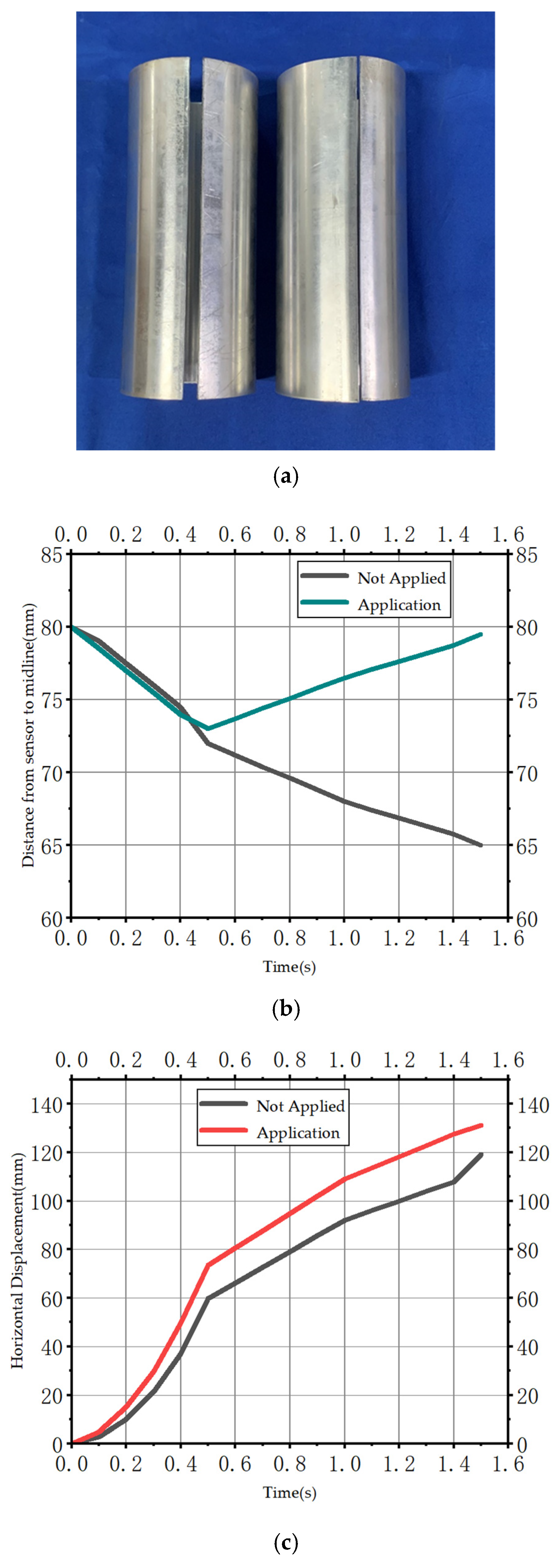
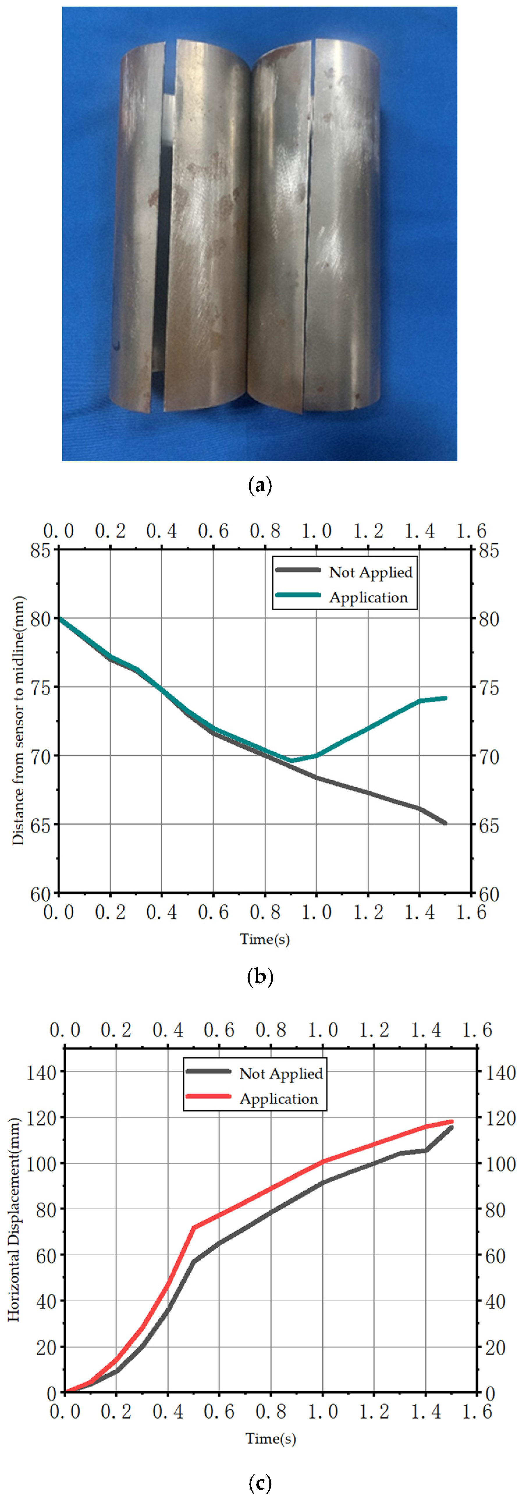
To further verify the superiority of the springback compensation control strategy using the CWP optimization algorithm, under the same conditions, MATLAB/Simulink (Version R2021b) was employed to simulate the control effects of the circular roll forming process with and without the springback compensation control strategy, as well as with and without CWP optimization.
To simulate the springback of the sheet metal during the circular rolling process, a springback interference quantity is added in the simulation. When the springback of the sheet metal is detected by the distance sensor, the controller adopting the springback compensation strategy will adjust the motor rotation angle to change the gap between the working roll and the driven roll, ultimately correcting the springback of the sheet metal. In contrast, the controller without the springback compensation strategy only adjusts the motor rotation angle based on the feedback from the encoder.
The simulation results of the circular roll forming control are shown in
Figure 10 (all three curves use the encoder as feedback). The curve without the springback compensation strategy fails to respond to the springback during the forming process and ultimately cannot reach the desired forming value. The curve that adopts the springback compensation and is controlled by the traditional fuzzy PID can eventually reach the expected value, yet the response during the control process is too slow, the overshoot is excessive, and the robustness is low, which is not conducive to actual production forming. The control strategy using springback compensation and the fuzzy PID controller optimized by CWP has higher control accuracy. It can not only ensure control precision but also maintain relatively stable operation during the control process, with a small overshoot and a fast response speed, meeting the requirements of the actual production process. The specific numerical values of various parameters for the three curves are presented in
Table 5.
The core of this research focuses on the construction of the system architecture and the verification of basic functions. For
Figure 8 and
Figure 10, our main concern is the impact of springback interference on the performance of the controller. By simulating the springback phenomenon of sheet metal in actual production, we incorporate the key factor of springback interference into the model. Although some preliminary explorations have been conducted regarding measurement noise or control delays, they have not reached a stage where they can be comprehensively and systematically presented. Currently, our emphasis is on establishing a fundamental understanding of the controller’s performance under idealized conditions.
To validate the core functions of the proposed roll bending process control scheme, regarding the performance of the optimization algorithm, our primary objective is to demonstrate the effectiveness of the entire control system in achieving precise roll bending results. Our work mainly revolves around the roll bending results, and using the proposed method, we have significantly improved the forming quality in these results.
Compared with the fuzzy PID control without CWP optimization, the response speed of the optimized fuzzy PID control has increased by 57.95%, the overshoot has decreased by 22.05%, and the control error has decreased by 0.158%.


