
Improved Low-Complexity, Pilot-Based Channel Estimation for Large Intelligent Surface Systems


Abstract
1. Introduction
1.1. Motivation
- Pilot-based techniques: these include methods such as Least Squares (LS) and Minimum Mean Square Error (MMSE).
- Machine learning-based methods: these leverage data-driven approaches for enhanced accuracy.
- Compressed sensing: this approach exploits the channel’s sparsity to estimate its parameters efficiently.
1.2. Pilot-Based Estimation
1.3. Novelty and Contribution
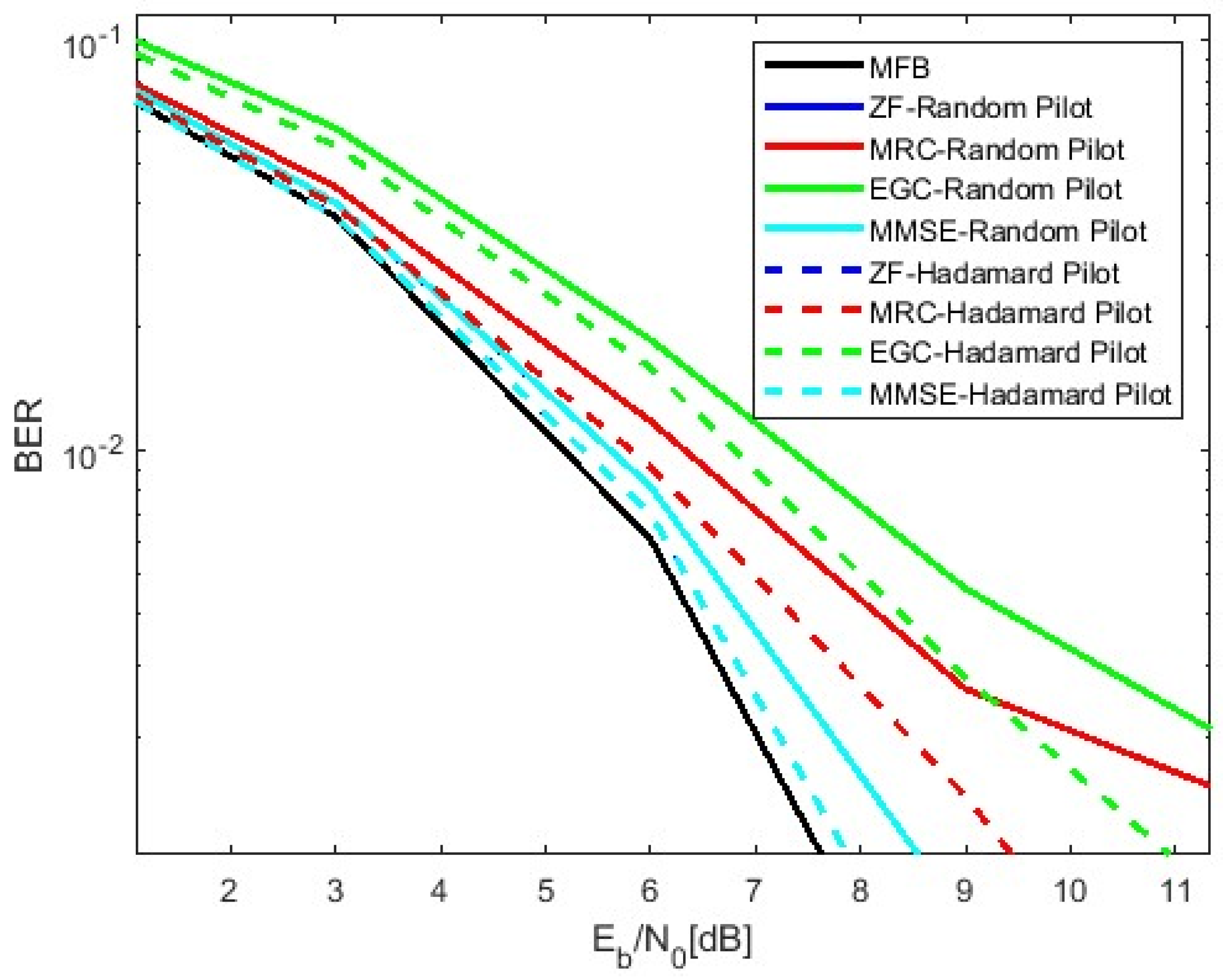
1.3.1. Enhanced Pilot-Based Channel Estimation with Hadamard Sequences
- Unlike traditional pilot sequences used in LIS systems [10], our method employs structured Hadamard sequences that are specifically optimized for low-SNR conditions, reducing cross-interference and improving channel estimation accuracy.
- Unlike conventional pilots, Hadamard sequences enable perfect orthogonality even under multipath fading, leading to more stable channel estimation.
1.3.2. Adaptive Pilot Power Optimization for Dynamic Channel Conditions
- Prior methods such as [11] use fixed pilot power, which does not account for varying noise conditions. Our approach introduces real-time adaptive power scaling, ensuring an optimal SNR while maintaining spectral efficiency.
- Our simulations show that adaptive power optimization reduces the BER more effectively than static power allocation, especially when the signal is weak.
1.3.3. Dynamic Pilot Number Adjustment to Reduce Overhead
- Traditional LIS estimation methods [12] rely on a fixed number of pilots, leading to inefficiencies. Our method uses adaptive pilot clustering, where pilot density increases only when needed.
- Our simulations show that adaptive power optimization helps lower the BER in changing environments better than static power allocation.
1.3.4. Iterative Channel Estimation for Progressive Accuracy Refinement
- Conventional LS estimation [13] relies on single-pass estimation, which can introduce high residual errors. We implement iterative refinement, where channel estimates improve progressively across iterations.
- Our approach gradually improves channel estimation over multiple iterations, making it more effective in noisy LIS environments.
1.3.5. Selective LIS Antenna Activation for Computational Efficiency
- Previous LIS systems [14] activate all antennas, increasing computational complexity. We propose intelligent antenna selection, activating only the most effective elements.
- This technique lowers computational effort by selecting only the most effective antennas while keeping channel estimation accuracy high.
1.3.6. LDPC-Assisted LS Estimation for Noise-Resilient Performance
- While LDPC codes have been used for error correction [15], their integration with LS-based LIS channel estimation has not been fully explored. We introduce a joint LS-LDPC decoding framework, which significantly improves channel robustness.
- Our method enhances channel robustness by combining LS estimation with LDPC decoding, improving the performance in high-noise conditions.
1.4. Characteristics of LIS Systems
- Large surface for signal reflection and transmission: unlike conventional MIMO systems with separate antennas, a LIS is a Large Intelligent Surface with many small antennas that control radio waves.
- More flexibility in selecting the signal path: a LIS improves signal quality and reduces interference, leading to improving spectral efficiency and coverage.
- Reconfigurable electromagnetic properties: unlike traditional base stations, a LIS can change wave properties for better transmission and lower energy consumption.
- Reduced hardware complexity: instead of complex and powerful equipment, a LIS uses simple and low-energy components for sending and receiving signals [14].
- Compatible with 6G networks: a LIS can match with 6G systems easily, providing ultra-reliable, low-latency communication (URLLC) and massive machine-type communication (m-MTC) through intelligent signal manipulation [18].
1.5. Objective and Organization of This Article
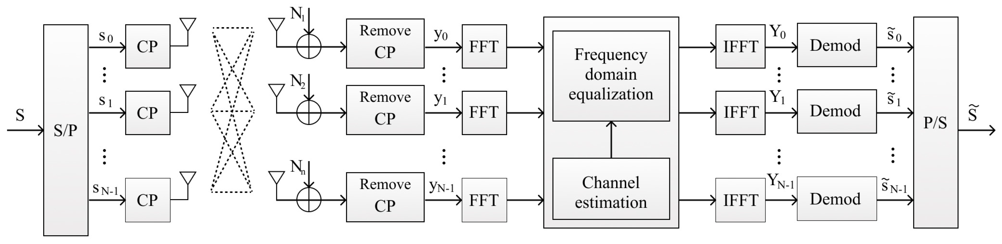
2. System Characterization
2.1. Channel Model
2.2. Receiver Algorithms
- ZF: this linear receiver inverts the channel matrix to cancel interference:
- MMSE: balances interference suppression and noise amplification by minimizing the mean square error:where and where is an identity matrix.
- MRC: this receiver combines the received signals based on the channel gains, improving the SNR:
- EGC: combines signals from multiple antennas with equal weights but adjusts phase to maximize received power:
- Iterative Block Decision Feedback Equalization (IB-DFE) is an advanced equalization technique used in communication systems to improve the performance in multipath or interference-limited environments. It iteratively refines the received signal by leveraging feedback from previously detected data, combining concepts from block-based processing and decision feedback. is a feedback filter matrix, stands for the forward filter matrix, and represents the detected signal from the previous iteration.
2.3. LS Channel Estimation
3. Receiver Design Considerations for LIS: Proposed Improvements in Channel Estimation
3.1. Optimized Pilot Design and Enhancing the Quality of Pilot Data
3.1.1. Orthogonal Pilot Sequences
- A.
- Hadamard as Orthogonal Pilot Sequences
| Algorithm 1: Hadamard Orthogonal Pilot-Based Channel Estimation |
Input:
Preprocessing:
Repeat: :
until:
Output:
|
- B.
- Properties of Hadamard Pilots:
- Orthogonality: each pilot sequence is orthogonal to others, allowing easy separation at the receiver [27].
- Low complexity: Hadamard sequences are computationally efficient to generate and process.
- Binary nature: They are simple to implement in hardware or software with entries.
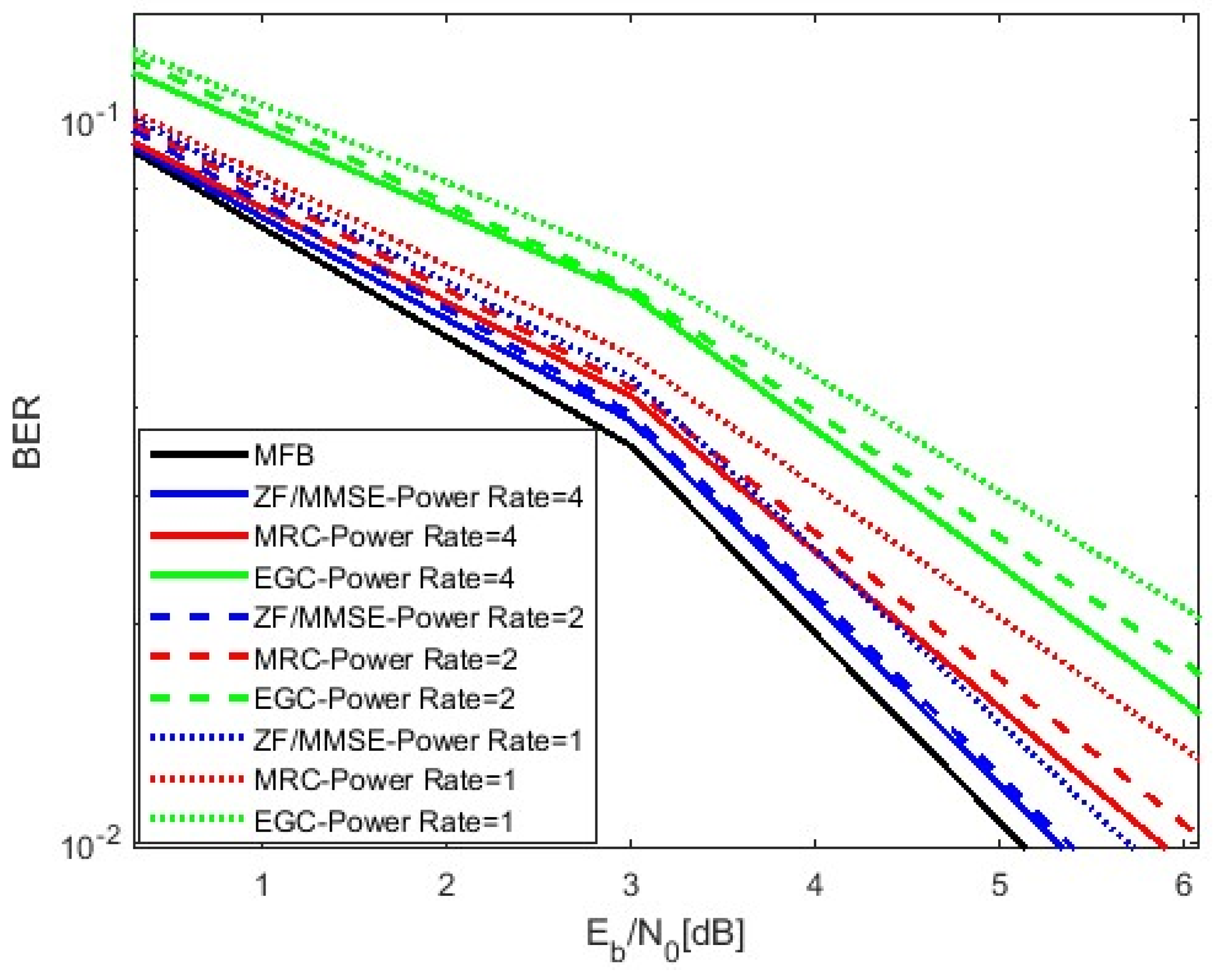
3.1.2. Pilot Power Optimization [19]
- Interpolation process: the estimated pilot-based channel matrix is interpolated across all subcarriers using a suitable interpolation function, which represents the chosen interpolation technique.
- Interpolation methods: commonly used interpolation techniques include the following:
- Linear interpolation: a simple method that connects pilot estimates with straight-line approximations;
- Spline interpolation: a more accurate approach that ensures smooth transitions between estimated points.
- Low-pass filtering: this mitigates noise effects and provides a smoother channel response by eliminating high-frequency artifacts.
- A.
- Defining the Optimization Problem
| Algorithm 2: Improved LS Channel Estimation with Increased Pilot Power |
Input:
Pilot symbol insertion:
LS estimation:
Interpolation:
Output:
|
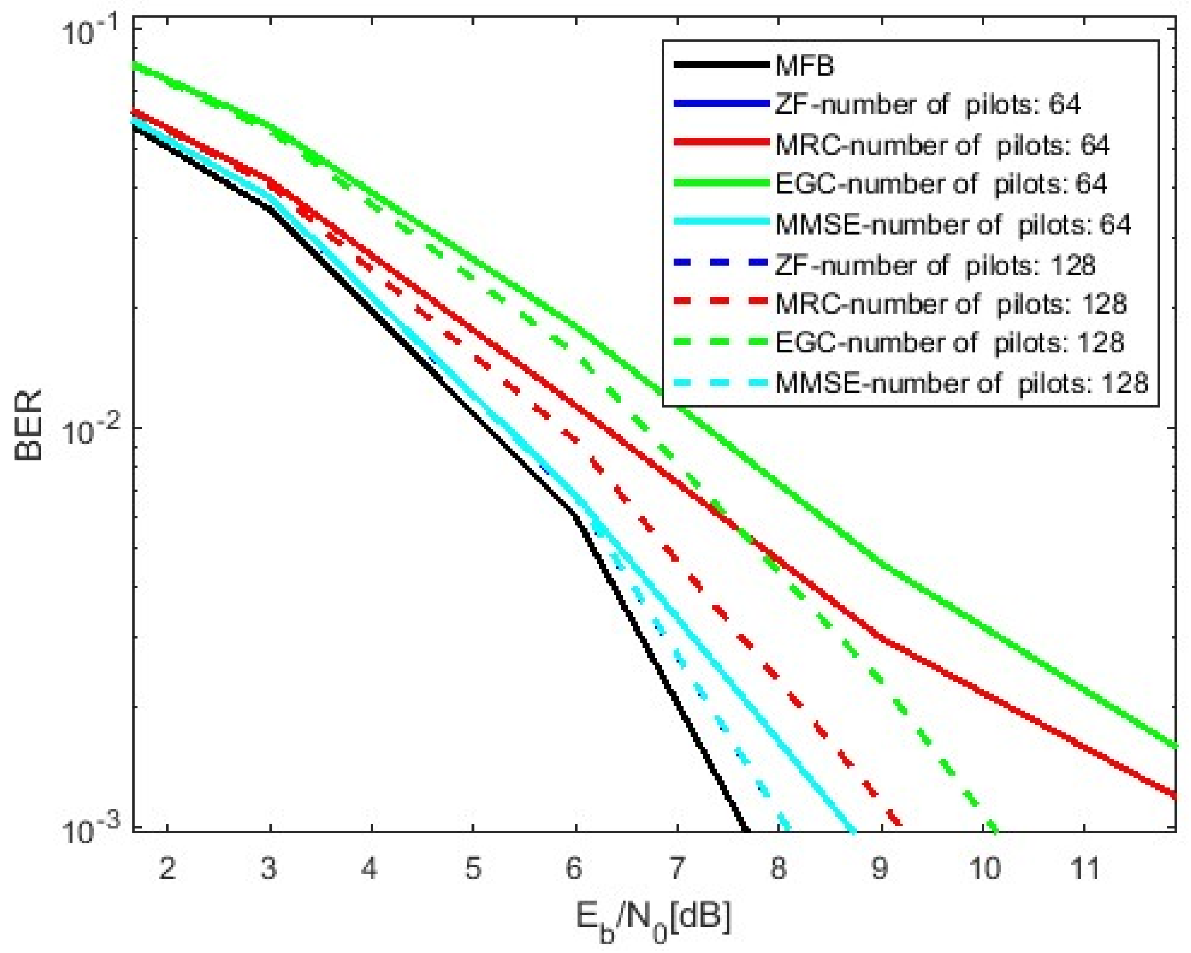
3.1.3. Increasing the Number of Pilots [19]
| Algorithm 3: Improved LS Channel Estimation with Increased Pilot Number |
Input:
Pilot symbol insertion:
LS estimation:
Improved interpolation:
Output:
|
- A.
- Optimization Problem for Number of Pilots
3.1.4. Adding Pilot Iteration to Channel Estimation [10]
- A.
- Optimization Problem for Number of Pilot Iterations
| Algorithm 4: Improved LS Channel Estimation with Increased Pilot Iteration |
Input:
Initial LS estimation:
Iterative refinement: For :
Improved interpolation:
Output:
|
3.2. Selective LIS Antenna Configurations and Increasing Channel Estimation Accuracy
Optimized Antenna Configurations and LIS Technology for Improved Channel Estimation
- Reduce computational complexity: focusing on fewer, high-impact antennas reduces the size of the matrices involved in channel estimation and subsequent signal processing, leading to faster computations [36].
- Maintain estimation accuracy: selecting the most relevant antennas ensures that the accuracy of channel estimation remains high, as only the antennas that contribute most to the signal quality are used.
- Enhance scalability: this approach is particularly beneficial for LIS systems with hundreds or thousands of antennas, where reducing the number of active antennas directly impacts the system’s computational efficiency.
- Energy efficiency: selective activation conserves power by disabling less effective antennas, improving overall efficiency.
- Interference: by focusing transmission and reception on high-quality antennas, the approach reduces multi-user interference.
3.3. LDPC Codes in Mitigating the Effects of Channel Estimation Errors
3.3.1. Reducing Sensitivity to Channel Estimation Errors
3.3.2. Improving Performance in Sparse Channels
3.3.3. Enhancing Spectral Efficiency and Energy Savings
4. Simulation Performance Results
- LIS channel modeling:
- The receiver is assumed to be in the near field of the LIS.
- The beam focuses on both angle and distance, unlike traditional far-field beamforming, which only considers direction.
- The simulation includes multipath reflections and time delays () to make it more realistic.
- Radio and environmental parameters:
- Carrier frequency: 2G Hz;
- Antenna spacing: ;
- User locations: randomly placed inside a room;
- Number of antennas: 4 × LISs (LIS antenna consist of four panels and each panel has 100 antennas; in total 4 × 100 = 400).
- Practical feasibility of LIS:
- LIS is modeled as an active antenna system, where each element has independent gain and phase control.
- Near-field beamforming is used to focus signals on users.
- Power adjustments are applied to keep the system practical.
- Real-world feasibility depends on hardware challenges, the real-time processing of many antennas, and precise phase/gain calibration.
- LDPC encoding and decoding:
- The LDPC encoder converts input bits into a longer coded sequence to improve error correction.
- The LDPC decoder uses a hard-decision method with a maximum of 20 iterations to decode the received data.
- The decoder stops early if the parity check is satisfied.
- LDPC integration with LIS:
- LDPC is applied to 4PSK modulation before transmission.
- After LIS-based transmission and reception, LDPC decoding is used to recover the original data.
- The simulation includes different equalization and interference cancellation methods (MRC, EGC, ZF, and MMSE).
- Pilot power optimization increases the strength of the pilot signals, improving the channel estimation accuracy but slightly reducing the spectral efficiency because it takes up more transmission power.
- Increasing the number of pilots helps achieve better accuracy but comes with a trade-off: higher complexity and reduced spectral efficiency due to the extra pilot overhead.
- Iterative estimation improves the accuracy over multiple iterations, but it requires more processing power, making it computationally expensive.
- Channel selection focuses only on the most useful LIS antennas, reducing the complexity while still maintaining good accuracy and efficiency.
- Hadamard orthogonal pilot sequences minimize interference between pilots, improving both the accuracy and spectral efficiency while keeping the complexity low.

| Improvement Method | Complexity | Energy Efficiency | Interference Reduction | Estimation Accuracy | Spectral Efficiency |
|---|---|---|---|---|---|
| Pilot power optimization | Moderate | Improves with careful scaling | Minimal impact on interference | Improves SNR for pilots | Moderate (trade-off with data throughput) |
| Increasing number of pilots | High (due to increased overhead) | Decreases due to higher overhead | No direct impact | Improves with increased reference data | Decreases due to increased pilot overhead |
| Iterative estimation | High (due to iterations) | Improves with better estimation accuracy | Moderate (depends on feedback accuracy) | Significantly improves after iterations | Improves by refining estimates |
| Channel selection | Low (reduces processing load) | Improves by focusing resources on high-impact antennas | High (reduces inter-user interference) | Moderate (focuses on relevant antennas) | Improves by reducing unnecessary overhead |
| Hadamard orthogonal sequences | Low (efficient generation) | Moderate (no direct impact on energy efficiency) | High (minimizes pilot contamination) | High (ensures minimal cross-correlation) | High (reduces pilot interference) |
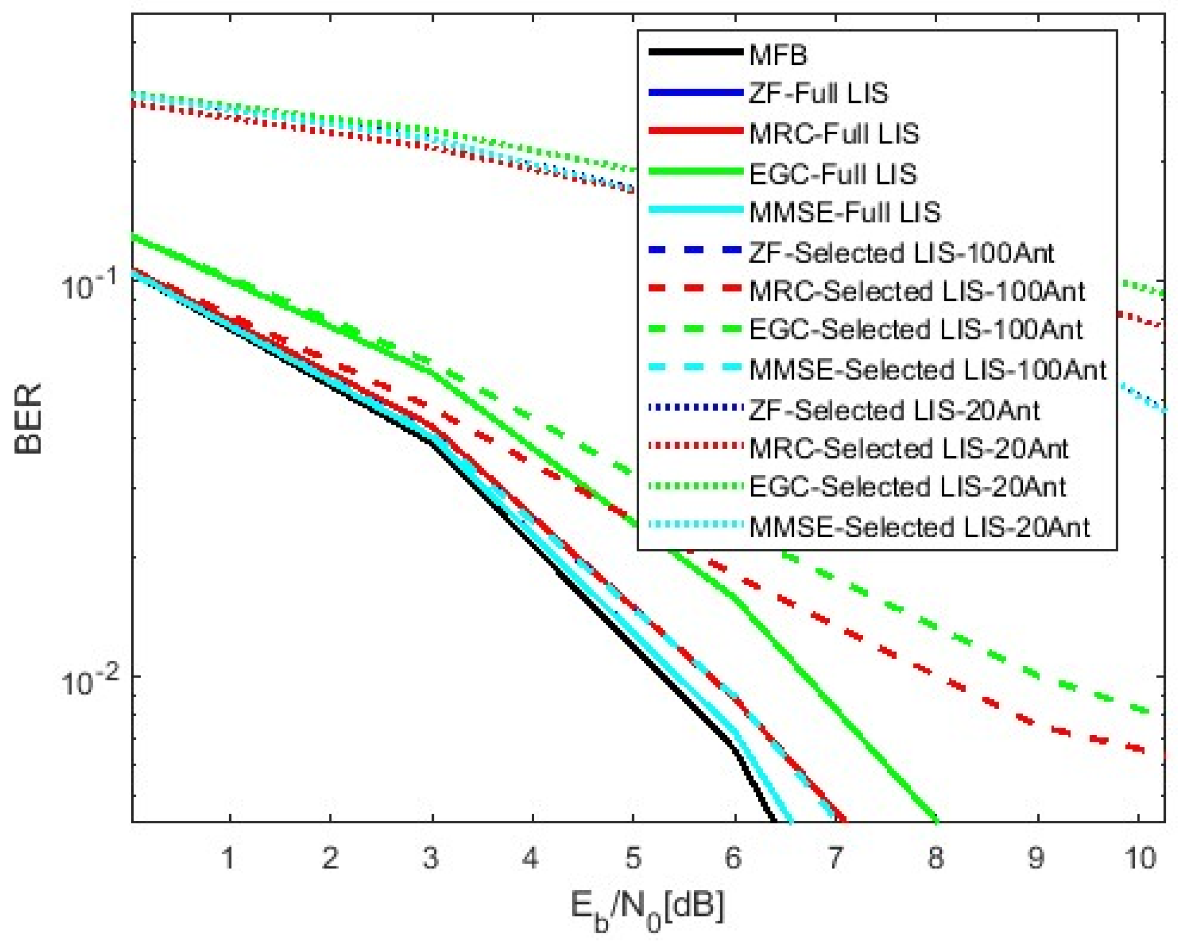
- 2.
- Computational Complexity (Figure 6)
- 3.
- Energy Efficiency (Figure 4)
- 4.
- Interference Reduction (Figure 5)
- 5.
- Spectral Efficiency (Figure 7)
5. Conclusions
6. Future Research
Author Contributions
Funding
Institutional Review Board Statement
Informed Consent Statement
Data Availability Statement
Acknowledgments
Conflicts of Interest
References
- Liang, Y.-C.; Long, R.; Zhang, Q.; Chen, J.; Cheng, H.V.; Guo, H. Large Intelligent Surface/Antennas (LISA): Making Reflective Radios Smart. J. Commun. Inf. Netw. 2019, 4, 40–50. [Google Scholar]
- Gashtasbi, A.; da Silva, M.M.; Dinis, R.; Guerreiro, J. On the Performance of LDPC-Coded Large Intelligent Antenna System. Appl. Sci. 2023, 13, 4738. [Google Scholar] [CrossRef]
- Han, Y.; Tang, W.; Jin, S.; Wen, C.-K.; Ma, X. Large Intelligent Surface-Assisted Wireless Communication Exploiting Statistical CSI. IEEE Trans. Veh. Technol. 2019, 68, 8238–8242. [Google Scholar]
- Almeida, I.; Guerreiro, J.; Dinis, R. Efficient Channel Estimation for LIS-based Systems. In Proceedings of the 2023 Photonics & Electromagnetics Research Symposium (PIERS), Prague, Czech Republic, 3–6 July 2023. [Google Scholar] [CrossRef]
- Gashtasbi, A.; da Silva, M.M.; Dinis, R. IRS, LIS, and Radio Stripes-Aided Wireless Communications: A Tutorial. Appl. Sci. 2022, 12, 12696. [Google Scholar] [CrossRef]
- Lee, S.J. Performance Enhancement of Codebook-Based Beamforming Using Least Squares Approach. IEEE Wirel. Commun. Lett. 2024, 13, 338–342. [Google Scholar]
- Liu, M.; Wang, H.; Li, Y.; Li, P. Research on Pilot-Based Channel Estimation Algorithms. In Proceedings of the 2019 International Conference on Electronic Engineering and Informatics (EEI), Nanjing, China, 8–10 November 2019. [Google Scholar] [CrossRef]
- Murad, M.; Tasadduq, I.; Otero, P. Pilots based LSE Channel Estimation for Underwater Acoustic OFDM Communication. In Proceedings of the 2020 Global Conference on Wireless and Optical Technologies (GCWOT), Malaga, Spain, 6–8 October 2020. [Google Scholar] [CrossRef]
- Bariah, L.; Muhaidat, S.; Sofotasios, P.C.; El Bouanani, F.; Dobre, O.A.; Hamouda, W. Large Intelligent Surface-Assisted Nonorthogonal Multiple Access for 6G Networks: Performance Analysis. IEEE Internet Things J. 2021, 8, 5129–5140. [Google Scholar]
- Ali, S.; Chen, Z.; Yin, F. Design of Orthogonal Uplink Pilot Sequences for TDD Massive MIMO under Pilot Contamination. J. Commun. 2017, 12, 40–48. [Google Scholar]
- Mohammadzadeh, S.; Rahmani, M.; Cumanan, K.; Burr, A.; Xiao, P. Pilot and Data Power Control for Uplink Cell-free massive MIMO. arXiv 2025. [Google Scholar] [CrossRef]
- Yu, Y.; Zhang, X.; Zhang, Z. Iterative Channel Estimation Using Superimposed Pilot for BICM-OFDM. In Proceedings of the 5th International Conference on Wireless Communications, Networking and Mobile Computing, Beijing, China, 24–26 September 2009. [Google Scholar] [CrossRef]
- Ohno, S.; Manasseh, E.; Nakamoto, M. How many known symbols are required for linear channel estimation in OFDM? In Proceedings of the IEEE International Conference on Acoustics, Speech and Signal Processing (ICASSP). Prague, Czech Republic, 22–27 May 2011. [Google Scholar] [CrossRef]
- Xu, C.; An, J.; Bai, T. Antenna Selection for Reconfigurable Intelligent Surfaces: A Transceiver-Agnostic Passive Beamforming Configuration. IEEE Trans. Wirel. Commun. 2023, 22, 7756–7774. [Google Scholar]
- Salari, S.; Ardebilipour, M.; Ahmadian, M.; Cances, J.P.; Meghdadi, V. Turbo Receiver Design with Carrier-Frequency Offset Estimation for LDPC-Coded MIMO OFDM Systems. In Proceedings of the 9th International Conference on Advanced Communication Technology, Gangwon, Republic of Korea, 12–14 February 2007. [Google Scholar]
- Alghamdi, R.; Alhadrami, R.; Lhothali, D.; Almorad, H.; Faisal, A.; Helal, S.; Shalabi, R.; Asfour, R.; Hammed, N.; Shams, A.; et al. Intelligent Surfaces for 6G Wireless Networks: A Survey of Optimization and Performance Analysis Techniques. IEEE Access 2020, 8, 202795–202818. [Google Scholar] [CrossRef]
- Zhu, Y.; Zheng, G.; Wong, K.-K. Stochastic Geometry Analysis of Large Intelligent Surface-Assisted Millimeter Wave Networks. IEEE J. Sel. Areas Commun. 2020, 38, 1749–1762. [Google Scholar]
- Almekhlafi, M.; Arfaoui, M.A.; Assi, C.; Assi, C.; Ghrayeb, A. Enabling URLLC Applications Through Reconfigurable Intelligent Surfaces: Challenges and Potential. IEEE Internet Things Mag. 2022, 5, 130–135. [Google Scholar]
- da Silva, M.M.; Dinis, R.; Guerreiro, J. A Low Complexity Channel Estimation and Detection for Massive MIMO Using SC-FDE. Telecom 2020, 1, 3–17. [Google Scholar] [CrossRef]
- Lam, C.-T.; Falconer, D.D.; Danilo-Lemoine, F.; Dinis, R. Channel Estimation for SC-FDE Systems Using Frequency Domain Multiplexed Pilots. In Proceedings of the IEEE Vehicular Technology Conference, Montreal, QC, Canada, 25–28 September 2006. [Google Scholar] [CrossRef]
- Gashtasbi, A.; da Silva, M.M.; Dinis, R. An Assessment of Receiver Algorithms for Distributed Massive MIMO Systems: Investigating Design Solutions and Performance. Electronics 2024, 13, 1560. [Google Scholar] [CrossRef]
- Pereira, A.; Bento, P.; Gomes, M.; Dinis, R.; Silva, V. Iterative MRC and EGC Receivers for MIMO-OFDM Systems. In Proceedings of the 2018 IEEE 87th Vehicular Technology Conference (VTC Spring), Porto, Portugal, 3–6 July 2018. [Google Scholar] [CrossRef]
- So, J.; Kim, D.; Lee, Y.; Sung, Y. Pilot Signal Design for Massive MIMO Systems: A Received Signal-To-Noise-Ratio-Based Approach. IEEE Signal Process. Lett. 2015, 22, 549–553. [Google Scholar]
- Do, D.-T.; Vu, D.-T. New orthogonal pilot scheme for semi-blind channel estimation in MIMO Systems. In Proceedings of the International Conference on Networking and Information Technology, Manila, Philippines, 11–12 June 2010. [Google Scholar] [CrossRef]
- Thaj, T.; Viterbo, E.; Hong, Y. Orthogonal Time Sequency Multiplexing Modulation: Analysis and Low-Complexity Receiver Design. IEEE Trans. Wirel. Commun. 2021, 20, 7842–7855. [Google Scholar]
- Siyau, M.F.; Ling, S.L.; Onalaja, O.; Onalajam, M. MIMO Channel Estimation and Tracking using a novel Pilot Expansion technique with Paley-Hadamard codes for future generation fast speed communications. In Proceedings of the Second International Conference on Future Generation Communication Technologies (FGCT), London, UK, 12–14 November 2013. [Google Scholar]
- Wu, H.-C.; Wu, Y. Efficient ICI Matrix Estimation Using Hadamard Sequences for Wireless OFDM Systems. In Proceedings of the VTC-2005-Fall. 2005 IEEE 62nd Vehicular Technology Conference, Dallas, TX, USA, 28 September 2005. [Google Scholar] [CrossRef]
- Song, Y.-K.; Kim, D.; Zander, J. Pilot power adjustment for saving transmit power in pilot channel assisted DS-CDMA mobile systems. IEEE Trans. Wirel. Commun. 2010, 9, 488–493. [Google Scholar]
- Han, W.; Wang, H. Joint Pilot Assignment and Uplink Power Allocation Scheme for Massive MIMO Systems. In Proceedings of the IEEE 20th International Conference on Communication Technology, Nanjing, China, 28–31 October 2020. [Google Scholar]
- Shen, Y.; Martinez, E. Channel Estimation in OFDM Systems; Freescale Semiconductor, Inc.: Austin, TX, USA, 2006. [Google Scholar]
- Zhanng, X.; Yuan, Z. The Application of Interpolation Algorithms in OFDM Channel Estimation. Int. J. Simul. Syst. Sci. Technol. 2016, 17, 11.1–11.5. [Google Scholar] [CrossRef]
- Liu, Y.; Deng, H.; Peng, C. Channel Estimation for RIS-Assisted MIMO Systems in Millimeter Wave Communications. Sensors 2023, 23, 5516. [Google Scholar] [CrossRef]
- Willink, T.J. Improving Power Allocation to MIMO Eigenbeams Uendr Imperfect Channel Estimation. IEEE Commun. Lett. 2005, 9, 622–624. [Google Scholar] [CrossRef]
- Zhang, Y.; Feng, W.; Ge, N. Adaptive Pilot Power Allocation for Distributed Antenna Systems with Large-scale CSI. In Proceedings of the 21st International Conference on Telecommunications (ICT), Lisbon, Portugal, 4–7 May 2014. [Google Scholar] [CrossRef]
- Coleri, S.; Ergen, M.; Puri, A.; Bahai, A. Channel Estimation Techniques Based on Pilot Arrangement in OFDM Systems. IEEE Trans. Broadcast. 2002, 48, 223–229. [Google Scholar] [CrossRef]
- Chen, X.; Shi, J.; Yang, Z.; Wu, L. Low-Complexity Channel Estimation for Intelligent Reflecting Surface-Enhanced Massive MIMO. IEEE Wirel. Commun. Lett. 2021, 10, 996–1000. [Google Scholar] [CrossRef]
- Li, Z.; Li, Y.; Ai, B.; Wang, D.; Yao, L. A Novel Channel Estimation Algorithm Based on Iterative Compensation. IEEE Trans. Broadcast. 2017, 63, 144–150. [Google Scholar] [CrossRef]
- Alghonaim, E.; Landolsi, M.A.; El-Maleh, A. Improving BER Performance of LDPC Codes Based on Intermediate Decoding Results. In Proceedings of the 2007 IEEE International Conference on Signal Processing and Communications (ICSPC), Dubai, United Arab Emirates, 24–27 November 2007. [Google Scholar]
- da Silva, M.M.; Dinis, R. On the Performance of LDPC-Coded Massive MIMO Schemes with Power-Ordered NOMA Techniques. Appl. Sci. 2021, 11, 8684. [Google Scholar] [CrossRef]
- Bala, I.; Arora, K.; Mijwil, M.M. Energy Optimized LDPC Codes for Next-Generation MIMO OFDM Systems. Iraqi J. Comput. Sci. Math. 2023, 4, 1. [Google Scholar] [CrossRef]


| Aspect | Previous Methods | Our Improvement |
|---|---|---|
| Enhanced pilot-based channel estimation | Conventional methods use fixed orthogonal pilots, leading to interference and limited spectral efficiency. | We introduce Hadamard-based dynamic pilot assignment, which significantly reduces interference and improves channel estimation accuracy under varying SNR conditions. |
| Pilot power optimization | Previous works rely on fixed pilot power allocation, which does not adapt to fluctuating channel conditions. | Our method dynamically adjusts pilot power based on real-time channel variations, ensuring an optimal SNR while maintaining spectral efficiency. |
| Adaptive pilot symbol allocation | Previous works rely on fixed pilot traditional approaches use a fixed number of pilot symbols, leading to inefficient estimation in low-SNR scenarios. | We propose adaptive pilot clustering, where the system selectively increases pilot symbols only when necessary, reducing unnecessary overhead. |
| Iterative channel estimation | Conventional LS estimation performs single-pass estimation, often leaving residual errors. | Our iterative refinement process progressively updates channel estimates over multiple iterations, leading to significantly improved accuracy, particularly in noisy environments. |
| Selective LIS antenna activation | Previous LIS systems activate all antennas, increasing complexity and computational burden. | We introduce intelligent antenna selection, where only the most effective antennas are used, reducing complexity without sacrificing accuracy. |
| LDPC-assisted LS estimation | LDPC codes have been used for error correction but were not integrated with LS estimation in LIS systems. | We develop a joint LS-LDPC decoding framework, which significantly enhances noise resilience and system stability in high-interference conditions. |
| Number of Pilots | Channel Estimation Accuracy | Spectral Efficiency | Pilot Overhead | Recommendation |
|---|---|---|---|---|
| 64 | Moderate | Medium | Medium | Best trade-off between accuracy and overhead |
| 128 | High | Low | High | Suitable for systems with limited antennas |
| Receiver Architecture | BER Performance | Complexity | Energy Efficiency | Interference | Spectral Efficiency | Accuracy |
|---|---|---|---|---|---|---|
| ZF | High | High | Moderate | Low | High | Moderate |
| MMSE | High | Moderate | Moderate | Good | Moderate | High |
| MRC | Moderate | Moderate | High | Moderate | High | High |
| EGC | Moderate | Low | High | Low | Moderate | Moderate |
Disclaimer/Publisher’s Note: The statements, opinions and data contained in all publications are solely those of the individual author(s) and contributor(s) and not of MDPI and/or the editor(s). MDPI and/or the editor(s) disclaim responsibility for any injury to people or property resulting from any ideas, methods, instructions or products referred to in the content. |
© 2025 by the authors. Licensee MDPI, Basel, Switzerland. This article is an open access article distributed under the terms and conditions of the Creative Commons Attribution (CC BY) license (https://creativecommons.org/licenses/by/4.0/).
Share and Cite
Gashtasbi, A.; Marques da Silva, M.; Dinis, R. Improved Low-Complexity, Pilot-Based Channel Estimation for Large Intelligent Surface Systems. Appl. Sci. 2025, 15, 3743. https://doi.org/10.3390/app15073743
Gashtasbi A, Marques da Silva M, Dinis R. Improved Low-Complexity, Pilot-Based Channel Estimation for Large Intelligent Surface Systems. Applied Sciences. 2025; 15(7):3743. https://doi.org/10.3390/app15073743
Chicago/Turabian StyleGashtasbi, Ali, Mário Marques da Silva, and Rui Dinis. 2025. "Improved Low-Complexity, Pilot-Based Channel Estimation for Large Intelligent Surface Systems" Applied Sciences 15, no. 7: 3743. https://doi.org/10.3390/app15073743
APA StyleGashtasbi, A., Marques da Silva, M., & Dinis, R. (2025). Improved Low-Complexity, Pilot-Based Channel Estimation for Large Intelligent Surface Systems. Applied Sciences, 15(7), 3743. https://doi.org/10.3390/app15073743