Article

Reliability Analysis of Hybrid Laser INS Under Multi-Mode Failure Conditions

1
School of Missile Engineering, Rocket Force University of Engineering, Xi’an 710025, China
2
Xi’an Aerospace Precision Electromechanical Research Institute, Xi’an 710129, China
3
School of Mechanics, Civil Engineering and Architecture, Northwestern Polytechnical University, Xi’an 710129, China
4
National Key Laboratory of Strength and Structural Integrity, Xi’an 710012, China
*
Author to whom correspondence should be addressed.
Appl. Sci. 2025, 15(7), 3724; https://doi.org/10.3390/app15073724
Submission received: 27 February 2025 / Revised: 18 March 2025 / Accepted: 24 March 2025 / Published: 28 March 2025
(This article belongs to the Section Applied Industrial Technologies)

Abstract

:
The hybrid laser inertial navigation system (INS) is increasingly vital for high precision under high-dynamic, long-duration conditions, especially in complex aircraft environments. Key components like the base, platform, and inner/outer frames significantly impact system accuracy and stability through thseir static and dynamic characteristics. This study focuses on minimizing deviations in the INS body coordinate system caused by elastic deformation under high overload by developing a mechanical simulation model of a rotational modulation structure and a structural model of the outer frame assembly. A reliability analysis model is established, considering both functional and structural strength failures. To address uncertainties from manufacturing, technical conditions, material selection, and assembly errors, a global sensitivity analysis based on Bayesian inference evaluates parameter contributions to functional failure probability, using a sample size of N1 = 5 × 10⁵. Additionally, uncertainty analysis via Sobol sequence sampling (N2 = 10,000) examines the impact of mean design parameter variations on failure probability for ZL107 and SiCp/Al aluminum matrix composite frames. Experimental verification concludes the study. The results indicate that the SiCp/Al composite material demonstrates superior mechanical performance compared to traditional materials such as the ZL107 aluminum alloy. The uncertainties in the inner frame thickness, inner frame material strength, and outer frame thickness have the most significant impact on the probability of functional failure in the hybrid INS, with sensitivity indices of δ 6 P { F } = 0.01657, δ 2 P { F } = 0.00873, and δ 4 P { F } = 0.00818, respectively. The mechanical properties of the outer frame structure made from SiCp/Al are significantly enhanced, with failure probabilities across three failure modes markedly lower than those of the ZL107 frame, indicating high reliability. In an impact test conducted on the product, the laser gyroscope worked normally, the hybrid laser system function was normal, and the platform angular velocity change corresponding to each impact direction was less than 12 ″/s. The maximum angle change of the inner and outer frames was 0.107°, indicating that the system structure can withstand large overloads and multiple levels of mechanical environments and has good environmental adaptability and reliability. This analytical approach provides a valuable method for reliability evaluation and design of new hybrid INS structures. More importantly, it provides insights into the influence of design parameter uncertainties on navigation accuracy, offering critical support for the advancement of inertial technology.

1. Introduction

The inertial navigation system (INS) is an autonomous navigation system that operates on the principles of Newtonian mechanics, measuring the acceleration of an aircraft in an inertial reference frame to calculate its velocity, displacement, attitude, and heading angle through integration [1,2,3]. During operation, INS offers several advantages such as not radiating energy externally, independence from external data, and immunity to electromagnetic interference, leading to its extensive use in aircraft and rockets. Advanced countries have consistently regarded INS as a critical technology, strongly supporting its development and optimization while maintaining strict control over related technology and products [4,5,6].
The concept of a hybrid INS was proposed by academician Feng Peide in 2015 [7], integrating a physically stabilized platform using digital servo control with a mathematically computed platform based on strapdown attitude calculations. Functionally, the hybrid INS not only isolates angular movements of the carrier, as a conventional INS does, but also achieves rotational capability, which enables inertial devices to rotate relative to the navigation frame, thereby enhancing error modulation [8].
Compared to a traditional platform-based INS [9] and “self-contained” INS [7], the hybrid laser INS introduces unique features in both principle and structure that impact its performance accuracy. This system presents numerous technical challenges such as the dual-frequency dithering characteristics of the laser gyroscope, which complicates stability control. Achieving optimal control performance requires an ideal design for the rotational mechanism and an understanding of its structural and mechanical transfer properties, providing a suitable operating environment for angular motion isolation under high-dynamic conditions. In the hybrid laser INS, the relative positioning between the inertial measurement unit (IMU), the rotational frame, and the base continuously changes, especially in high-overload and impact environments, affecting INS accuracy. This necessitates an in-depth analysis of the mechanical characteristics of the hybrid laser INS under high dynamics and overload conditions.
Components such as the base, platform, and inner and outer frames are essential to the hybrid laser INS, where their static and dynamic properties critically affect the system’s accuracy and stability [10]. Under mechanical conditions involving high overloads and severe impacts, structural elastic deformation can lead to deviations in the INS body coordinate system from the virtual coordinate system [11]. Therefore, structural elements such as the base, platform, and frames must exhibit high static and dynamic performance to ensure the accuracy and reliability of the hybrid INS [12]. During operation, the INS endures complex vibrational loads; when the frequency of these external vibrations is close to the natural frequency of structural elements, resonance can occur, severely impacting the accuracy and stability of the INS and even causing potential damage to the entire measurement system [13]. Additionally, the frames bear the weight of the platform and gyroscopes, causing deformation. Consequently, requirements for rigidity, strength, dimensions, and tolerances in components such as the base, platform, and frames are stringent. The stability of the reference coordinate system within the inertial measurement system is heavily influenced by factors such as structural deformation, angle sensor accuracy, motor control precision, and gyroscope accuracy. However, improving angle sensor accuracy, motor control precision, and gyroscope accuracy is often costly and complex. Hence, enhancing structural rigidity and strength to reduce elastic deformation under high overload and impact conditions, thereby minimizing deviation of the INS body coordinate system from the virtual coordinate system, is the most direct approach.
Scholars have conducted extensive research on improving structural rigidity in INSs. For instance, Huang Yitao et al. [14] applied finite element analysis to assess and optimize the static and vibrational modes of an INS frame to enhance rigidity and anti-vibration performance. Similarly, Zhang Su et al. [15] performed mechanical tests on aluminum–lithium alloy 8090, using the results to simulate and iteratively optimize the finite element analysis of an aluminum–lithium alloy platform in a strapdown INS.
In addition to structural optimization, material selection significantly impacts structural performance [16]. Traditional materials such as aluminum alloys are commonly used for structural components, such as the base, platform, and frames, in hybrid INSs. However, with advancements in new composite materials, inertial measurement systems have entered a phase characterized by “high precision”, “miniaturization”, and “extended service life”. In this phase, the inherent limitations of traditional materials, such as low rigidity and dimensional instability, have become prominent obstacles to achieving high-precision INSs. Therefore, the use of new materials is essential for the progress of inertial technology and military equipment. Aluminum matrix composites, which offer the benefits of being lightweight and possessing high elastic modulus and high dimensional stability, have become crucial in aerospace applications and are widely used in antennae, skins, and support structures for aircraft [17,18,19,20,21].
Traditional inertial measurement device analysis and optimization generally rely on deterministic system parameters and optimization models, using classical deterministic methods for model solutions [22,23]. However, in engineering practice, uncertainty factors are inevitably present in the parameters of the base, platform, and inner and outer frames of inertial measurement devices, such as geometric parameters, measurement errors, and material properties. Although these uncertainties are typically minor, the nonlinear nature and multi-system coupling of the inertial measurement system can cause significant fluctuations in structure or system performance, potentially preventing it from fulfilling its intended function and even leading to serious consequences. There are two main approaches to addressing these uncertainties: (1) minimizing or controlling their range by enhancing component precision and reducing tolerance bands during manufacturing, although uncontrollable factors may limit the effectiveness of this approach; (2) mitigating the impact of uncertainties on structural performance, aiming to make performance less sensitive to these variations and to ensure high reliability [24].
Conventional reliability analysis methods include approximate analytical methods, numerical simulation, and surrogate models, all applicable to hybrid inertial measurement system reliability analysis [25]. The approximate analytical method mainly refers to the first-order reliability method (FORM) [26] and the second-order reliability method (SORM) [27], which estimate failure probability by linearizing the failure boundary at the design point. However, these methods require explicit mathematical models of the inertial measurement system and perform poorly in highly nonlinear problems. The numerical simulation approach, primarily the Monte Carlo method [28], uses a set number of samples to obtain response values and calculates failure probability based on these samples. Although the accuracy of this method improves with sample size, the computational and time costs are substantial, especially for complex precision systems such as inertial measurement systems, where obtaining failure samples is costly and impractical for large datasets. Therefore, surrogate models are commonly employed in engineering to improve computational efficiency. Surrogate models use limited sample points to predict outputs in real time, reducing the need for computationally intensive finite element simulations or physical model calculations. Popular surrogate models include response surfaces [29], neural networks [30], and Kriging models [31]. Among these, the Kriging model is widely used for its strong predictive ability and limited constraints, achieving the required precision with fewer samples and enhancing computational efficiency [32].
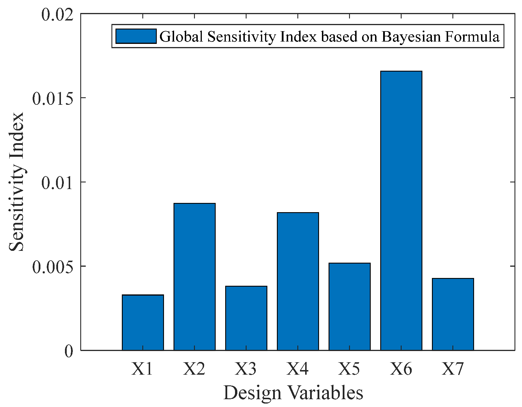
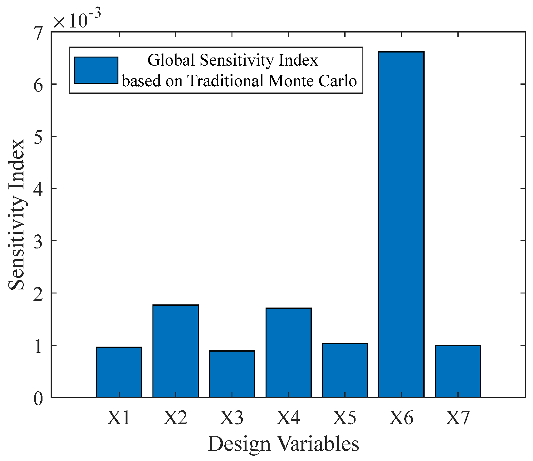
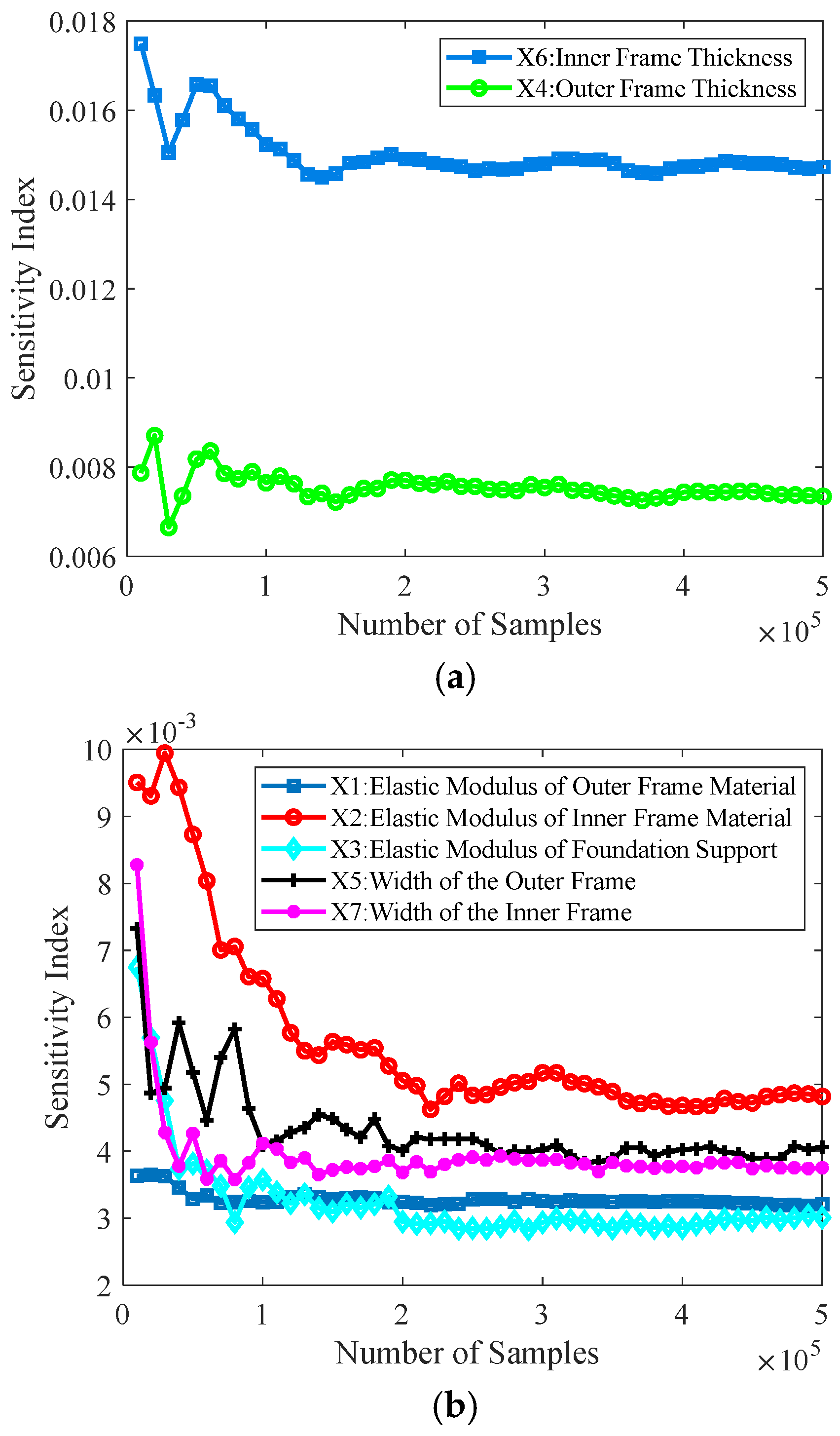
Sensitivity analysis is a widely used uncertainty analysis method that explores the contribution of input variable uncertainty to output response uncertainty and ranks the importance of input variables. Sensitivity analysis includes local sensitivity analysis (LSA) and global sensitivity analysis (GSA). Local sensitivity is limited by the selection of nominal points and cannot directly reflect the contribution of the interaction between a single input variable and multiple input variables to the statistical characteristics of output performance, lacking global and computational stability. Global sensitivity analysis, also known as importance measure analysis, aims to study the impact of input basic variables on output performance uncertainty in structural systems and rank the importance of input variables based on their degree of impact. Based on Bayes’ global sensitivity analysis, it is possible to evaluate the impact of all input variables and their interactions on the output results, not just local variations. This makes the analysis results more comprehensive and able to capture the complex nonlinear relationships and interaction effects in the system.
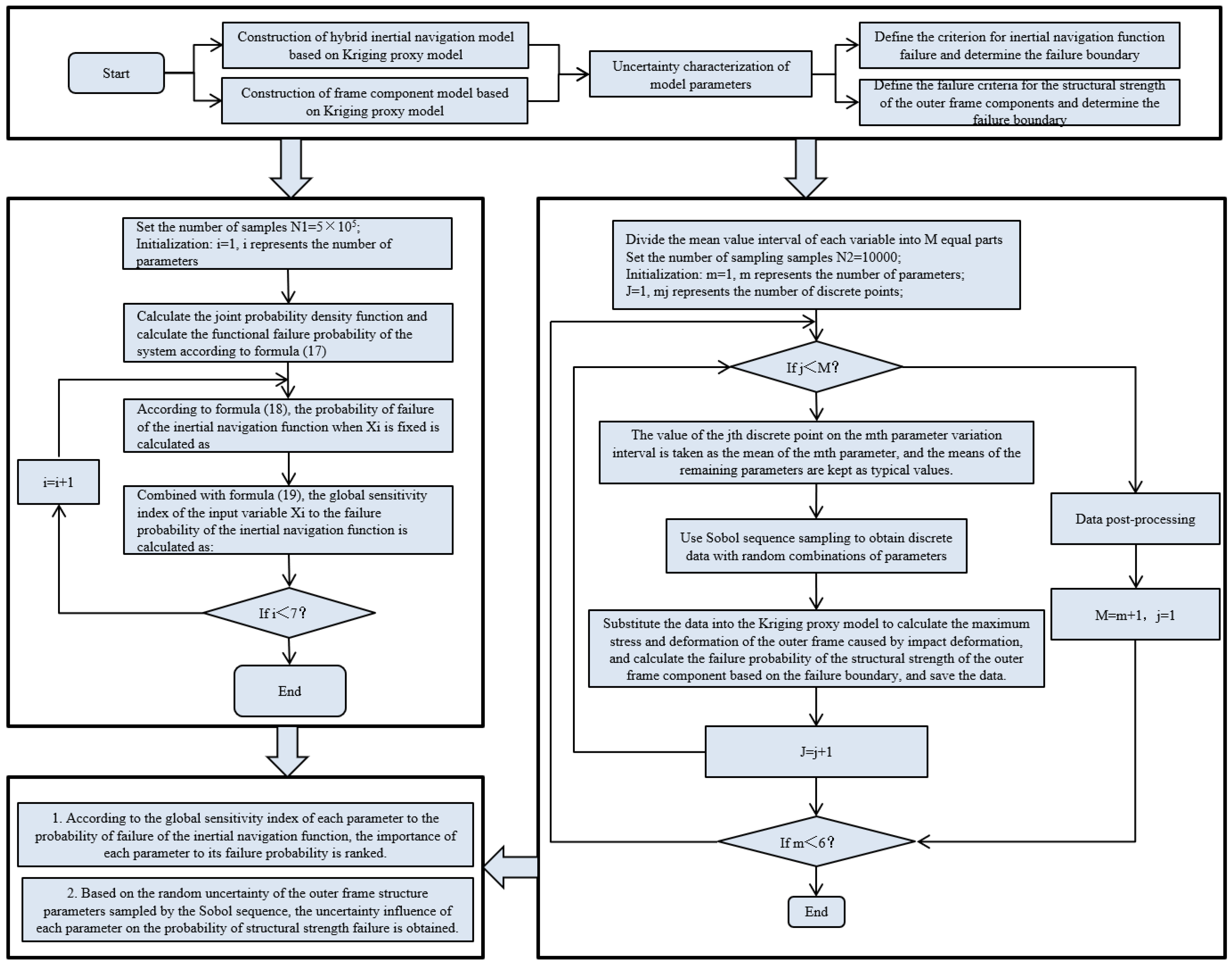
In light of this, this study develops a mechanical simulation model for a rotational modulation structure in a novel hybrid laser INS, isolating angular movements and simulating the major mechanical environments faced by high-dynamic aircraft. Key structural components are analyzed for mechanical performance under high overloads across different composite materials. Using MATLAB 2018b, an adaptive Kriging surrogate model is constructed, incorporating the unavoidable uncertainties in parameters such as geometry, measurement error, and material strength of components such as the base and frames. The model also considers structural deformation and failure in a half-sine shock environment (120 g, 11 ms), using deviations in the INS body coordinate system from the virtual coordinate system as the failure criterion. A reliability analysis model is established based on INS functional failure, applying Bayesian global sensitivity analysis to quantify the contribution of each input variable to failure probability. A dual-random uncertainty analysis model for frame component strength failure is also developed, accounting for dual-random uncertainties in parameter distributions for the outer frame structure. Using Sobol sequence sampling, the model simulates random phenomena to study the effect of changes in input mean values on structural strength failure probability. This analytical approach not only provides a reliability evaluation and design method for novel hybrid INS structures but also offers insights into how design parameter uncertainties affect INS navigation accuracy, thereby supporting advancements in inertial technology.

2. Mechanical Simulation Analysis of Hybrid Laser INS Structure

2.1. Working Principle of the Hybrid Laser INS

The hybrid laser inertial navigation system (referred to as “hybrid INS”) serves as a primary sensor device in the control system of high-performance, maneuverable missile projects. During the flight phase, the inertial assembly operates in a rotational modulation mode, isolated from angular movement. Its output, processed through the flight control computer, provides the missile’s position, velocity, and attitude while simultaneously outputting angular rate signals for attitude control.
A schematic of the working principle is shown in Figure 1.

2.2. Mechanical Simulation Analysis of the Hybrid Laser INS Structure

2.2.1. Structural Mechanical Simulation Model of the Rotational Modulation Mode for Angular Motion Isolation

The current mainstream inertial navigation systems are platform inertial navigation systems and strapdown inertial navigation systems. Strapdown systems, through the addition of a frame rotation device, effectively address self-calibration and rapid, precise self-alignment under installation conditions, achieving “three self” functions. However, during flight, the frame remains mechanically locked, meaning it essentially still functions as a strapdown system, and errors caused by missile body angular motion cannot be fully eliminated, limiting accuracy improvements.
The hybrid laser INS is a new type of INS designed to meet the demands of high-dynamic, long-duration aerospace vehicles. To improve navigation accuracy under such conditions, it utilizes frame stability control to isolate interference from carrier angular motion during navigation. This method, combined with the strapdown algorithm in rotational modulation, suppresses coupling errors between angular and linear motion, effectively separating and compensating for accelerometer drift and partial gyroscope errors. This aims to meet new accuracy requirements for high-dynamic, long-duration carriers.
This paper investigates the mechanical behavior of a hybrid INS structural mechanical simulation model in the rotational modulation mode for angular motion isolation, focusing on its performance under high dynamics and large overloads. The structural mechanics simulation model of the rotational modulation mode with angular motion isolation is shown in Figure 2. Frame stiffness directly determines load-bearing capacity, with the inner and outer frames, shaft-end modules, and rotation locking mechanism working together to achieve rotation and positioning of the shaft systems. Figure 2 shows a simplified model diagram of the hybrid INS structure, and Figure 3 shows a simplified model diagram of the outer frame assembly.

2.2.2. Finite Element Modeling of Hybrid INS Structure

(1)
Simplification of the Hybrid INS Structural Model
For CAE analysis, it is essential to reduce simulation time and improve mesh quality in the finite element model by simplifying the 3D models of various components in the hybrid INS according to simplification principles. Figure 4 and Figure 5 shows a simplified diagram of the outer frame and shaft end component model.
(2)
Contact Settings of the Hybrid INS Structure Model
The simplified Pro/E model of the laser INS structure was imported into FEA software for finite element analysis (FEA) (the finite element analysis software used in this article is the commercial software ANSYS 2017). Contact settings were applied between components, including bonded contact and frictional contact. Figure 6 shows the contact setting between the screw and the shaft end assembly
(3)
Mesh Generation of the Hybrid INS Structure Model
Grid partitioning is an important step in finite element analysis, which discretizes a continuous solution area (such as structure, field, etc.) into many small elements that are connected to each other through nodes, forming a grid composed of a finite number of elements. In reality, objects are continuous, while finite element analysis requires transforming them into discrete computational models.
During the grid generation process, certain parts are manually controlled to improve grid quality. In finite element analysis software, the Solid186 element type is used to simulate components with complex geometric shapes and large thicknesses in the system. By dividing irregularly shaped components with large volumes into regular structures, the mesh quality is improved, and the geometric characteristics of each component in the system can be well adapted. This element type can accurately reflect the mechanical behavior of materials, especially the characteristics of isotropic and anisotropic materials. To reduce computational costs, including computation time and memory usage, and ensure a certain level of computational accuracy, this article sets the grid division accuracy to medium and imposes corresponding limitations on grid size based on analysis needs and the size characteristics of components. A “medium” grid can greatly reduce computation time while meeting basic engineering accuracy requirements. Figure 7 shows the finite element mesh division of the entire inertial navigation system structure.

2.2.3. Mechanical Simulation Analysis of the Hybrid INS Structure

Throughout its development, transportation, and operation phases, the hybrid INS structure experiences various shock environments such as engine ignition and separation shocks, explosion shocks, and high-speed aerodynamic shocks during atmospheric re-entry. Shock loads critically affect the strength and stiffness of the inertial group structure. As shock is a complex physical process, assessing structural reliability under shock conditions is crucial.
Currently, hybrid INS structural components are primarily made from aluminum alloys. To achieve lightweight, high-precision, and high-overload performance, a well-balanced design of mass and stiffness is challenging. The emergence of SiCp/Al composite materials provides a feasible solution. These aluminum-based composites combine metal plasticity and toughness with ceramic properties, offering high strength, high modulus of elasticity, dimensional stability, and good thermal and wear resistance, while addressing the high cost, toxicity, and processing limitations associated with beryllium materials. Table 1 compares SiCp/Al composite materials with other commonly used materials.
To fully understand the static and dynamic characteristics of the SiCp/Al composite structure, this study used a simplified model of the inertial measurement device, as shown in Figure 2, to conduct semi-sine shock and modal mechanical simulations, comparing the performance of traditional ZL107 materials and SiCp/Al composites. The conditions and waveform of the semi-sine shock pulse are presented in Table 2 and Figure 8. The comparison results are shown in Table 3.
As shown in Table 3, the overall dynamic frequency of the SiCp/Al composite structure during modal analysis is significantly higher than that of conventional ZL107 mate-rials, with a first-order dynamic frequency for the SiCp/Al composite at 4336.7 Hz, ap-proximately 14.90% higher than that of the ZL107 material. This suggests that using mate-rials with higher specific stiffness can significantly increase dynamic frequencies. Under the conditions of the semi-sine shock pulse waveform in Table 2 and Figure 8, structural mechanical simulations were conducted on the hybrid INS, and the data are shown in Table 3.
Comparing structural deformation for the two composite materials, the ZL107 material exhibited the largest deformation, with a maximum deformation of 0.34252 mm on the platform structure, while the inner and outer frames and base experienced minor deformation. The SiCp/Al composite demonstrated a significantly reduced deformation, suggesting greater resistance to plastic deformation failure and higher overload tolerance compared to the ZL107 material. The maximum deformation rate difference for the inner and outer frames between the two materials was −14.81% and −14.76%, respectively. At the same time, the safety factor corresponding to the maximum stress of SiCp/Al composite material is significantly higher than that of ZL107 material. This indicates that using high-strength, high-modulus materials for the inner and outer frames notably improves the mechanical performance of the hybrid INS under high overload and dynamic conditions.

3. Reliability Analysis Model for the Hybrid INS Based on Kriging Surrogate Model

As critical components of an inertial navigation device, the base, platform, and inner and outer frames significantly impact the accuracy and stability of the INS system due to their static and dynamic properties. Under high-overload and large-shock mechanical conditions, elastic deformation in these structures can more easily cause the coordinate system of the inertial group body to deviate from the virtual body coordinate system. Based on the conclusions in Table 3, the base, platform, inner frame, and outer frame all experience some degree of elastic deformation under shock conditions, where δ_Platform > δ_Inner Frame > δ_Outer Frame > δ_ Foundation. The stability of the inertial measurement system’s reference coordinate system is primarily affected by deformation, angle sensor accuracy, motor control precision, and gyroscope accuracy. However, improving the angle sensor accuracy, motor control precision, and gyroscope accuracy can be costly and challenging. Thus, as the inner and outer frames are the direct structural components connecting the platform assembly, shaft end assembly, and base assembly, increasing their structural stiffness and strength to reduce elastic deformation under overload conditions is the most direct method to minimize the deviation of the inertial measurement unit’s coordinate system from the true coordinate system.
When the inertial measurement unit body is mounted on the projectile without installation errors, the virtual body coordinate system of the inertial group is parallel to the projectile coordinate system. When the frame is in its initial strapdown lock state, the inertial group body coordinate system coincides with the virtual coordinate system, as shown in Figure 9.

3.1. Kriging Surrogate Model

According to Kriging theory, the relationship between the output response G x and input variable x can be represented as Equation (1):
G x = f T x β + z x
where:
f x is the regression polynomial basis function vector;
β is the vector of regression coefficients;
z x is a Gaussian random process with zero mean, and the covariance function is Equation (2):
cov z x i , z x j = σ z 2 R x i , x j ; θ
where:
σ z 2 is the variance of the Gaussian process;
R x i , x j ; θ is the correlation function with parameter vector θ , represented as Equation (3):
R x i , x j ; θ = k = 1 m exp θ k x i k x j k 2
with x i k and x j k as the k-th elements of vectors x i and x j , respectively.
Given a training sample set of size S 0 , the unbiased estimate of G x and prediction error are defined as follows Equations (4) and (5):
μ G x = f T x β + r T x R 1 Y F β
σ G 2 x = σ 2 1 + u T x F T R 1 F 1 u x r T x R 1 r x
where:
β is the estimated value of β ;
r x is the correlation function vector between the training sample points and the prediction point;
Y is the response of the training sample;
F is the regression matrix, Refer to Equations (6) and (7) for definition.
F = f T x 1 , f T x 2 , , f T x N T
u x = F T R 1 r x f x
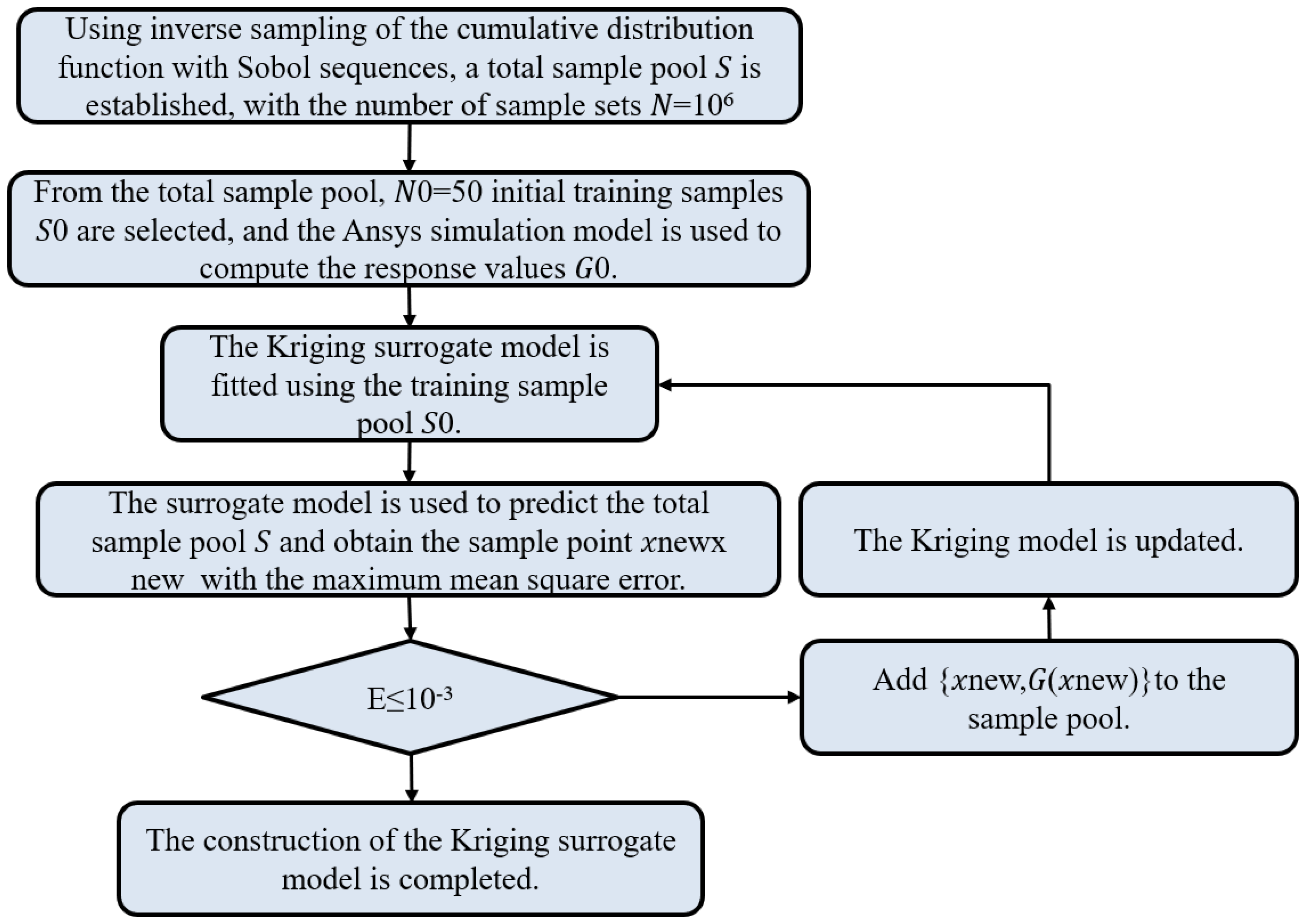
To improve the model’s prediction accuracy, this study uses the mean square error method to train the Kriging model by selecting points (Equation (8)) with the highest prediction error as new training points, updating the Kriging model:
x n e w = arg max s 2 x
where s is the standard deviation.
The convergence condition for building the Kriging model is determined as follows Equation (9):
E = T M T 1 / T 1 10 3
where T = max s , T 1 is the maximum standard deviation before adding a point. The smaller the value of E , the more accurate the Kriging model prediction becomes. Figure 10 shows the solution process of the Kriging surrogate model.

3.2. Representation of Random Uncertainty

According to the design requirements for the mixed inertial navigation system, the structural stiffness of the base, platform, and internal and external frames must be increased to reduce the deviation of the platform coordinate system from the true inertial coordinate system due to elastic deformation under overload conditions such as impacts and vibrations. The internal and external frames, serving as the direct structural components connecting the platform and the shaft-end assembly as well as the base assembly, have high requirements for part stiffness, strength, dimensions, and tolerances. However, significant uncertainties exist in the design and manufacturing processes of these parts. This uncertainty mainly arises from manufacturing process errors related to the material property parameters selected for the components. Taking aluminum alloy as an example, its forming performance is related to the alloy composition ratio, which can result in significant strength variations among different series of aluminum alloys. Additionally, during the structural processing of the components, factors such as manufacturing environment, technical conditions, and installation errors lead to uncertainties in geometric dimensions.
This paper selects key dimensional parameters and material performance parameters during the part design process as the subjects of study. Combining engineering experience with existing data, it is known that the elastic moduli of the materials for the outer frame E O u t e r   F r a m e , inner frame   E I n n e r   F r a m e , and foundation support E F o u n a t i o n   S u p p o r t , as well as the thicknesses H O u t e r   F r a m e , W O u t e r   F r a m e , H I n n e r   F r a m e , and W I n n e r   F r a m e of the outer and inner frames, follow a normal distribution. The specific distribution information is presented in Table 4. At the same time, since the outer frame assembly is a critical load-bearing component connecting the base and the platform, this paper emphasizes selecting key parameters from the outer frame design process and interface dimensions with the shaft-end and platform components. These parameters include the roundness R of the outer frame, thickness H of the outer frame, width B of the outer frame, mounting interface D of the platform, motor mounting interface 1 d 1 , and motor mounting interface 2 d 2 , as illustrated in Figure 11. The specific distribution information for these parameters is presented in Table 5.

3.3. Reliability Analysis Model for Mixed Inertial Navigation Based on Failure

In reliability theory, the performance function is a function of basic random variables. Let Y = g x be the performance function of the mixed inertial navigation structure, where x = x 1 , x 2 , x m represents an m-dimensional random variable with a joint probability density function f x . The failure domain is defined as Equation (10):
F = x : g x 0
The indicator function (Equation (11)) for the failure domain is I F x :
I F x = 1 x F 0 x F
Thus, the failure probability can be expressed as Equation (12):
P f = F f x d x = R n I F x f x d x = E I F
Using the Monte Carlo method in reliability theory, the failure probability of the mixed inertial navigation system can be computed using the mathematical expectation of the failure domain indicator function (13):
P f = 1 N j = 1 N I F x j = N f N
where N is the total number of samples, and N f is the number of samples falling into the failure domain.
This paper establishes a reliability analysis model for the mixed inertial navigation system based on failure probability, focusing on the following two aspects:

3.3.1. Considering the Failure Criterion for the Navigation Function of the Mixed Inertial Navigation System Under Overload Conditions

As shown in Figure 9, when the coordinate system of the inertial navigation system ( o x b t y b t z b t ) deviates from the virtual body coordinate system ( o x b t 0 y b t 0 z b t 0 
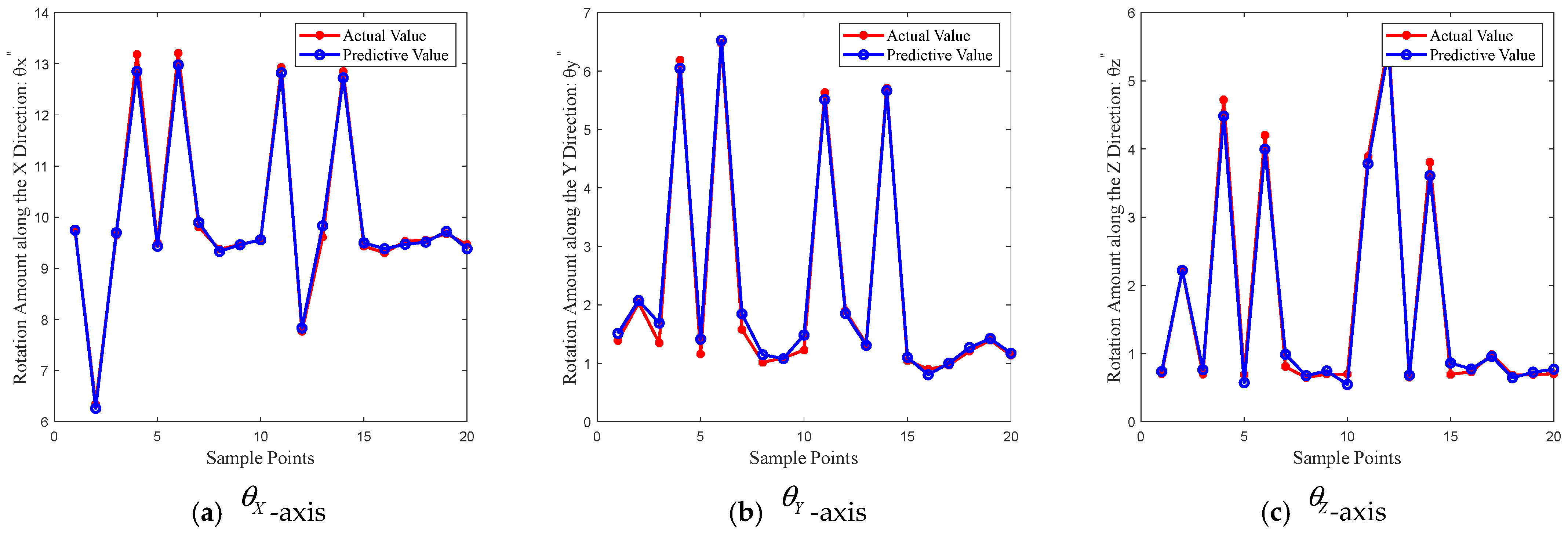
) beyond a certain range during impact overload conditions, it is determined that the navigation function of the mixed inertial navigation system has failed. By examining the X, Y, and Z axes of the mixed inertial navigation system, the degree of deviation of the coordinate systems due to elastic displacements under large overload impacts is studied. Failure functions for each of the three axes are established. According to the requirements of a certain new type of mixed laser inertial navigation system and performance enhancement task specification, the allowable fluctuation errors θ X * , θ Y * , and θ Z * in the X, Y, and Z axes due to elastic displacement are set, as detailed in Table 6. Among them, it is required that the maximum installation error of instruments in three directions installed in a mechanical environment should not exceed 8 inches, the safety factor of the outer frame in a mechanical environment should not be less than 2.0 (safety factor = ultimate stress/allowable stress), the deformation displacement should not exceed 0.052 mm, and the weight should not exceed 0.8 Kg. To ensure the normal operation of the mixed inertial navigation system, it is crucial that the fluctuation range of the three coordinate axes of the inertial navigation system under impact overload conditions meets the requirements for stable navigation functionality. The failure function g x of the mixed inertial navigation system is thus established, as detailed in Equations (14)–(16), with the corresponding functions being g 1 x ,   g 2 x ,   g 3 x , where x = x 1 , x 2 , x 3 , x 4 , x 5 , x 6 , x 7 .
The function corresponding to the failure of the X-axis inertial navigation function is Equation (14):
g 1 x = θ X * θ X b t θ X b t 0
The function corresponding to the failure of the Y-axis inertial navigation function is Equation (15):
g 2 x = θ Y * θ Y b t θ Y b t 0
The function corresponding to the failure of the Z-axis inertial navigation function is Equation (16):
g 3 x = θ Z * θ Z b t θ Z b t 0

3.3.2. Consideration of Structural Strength Failure Criteria as the Failure Criterion for the Outer Frame Assembly Under Overload Conditions

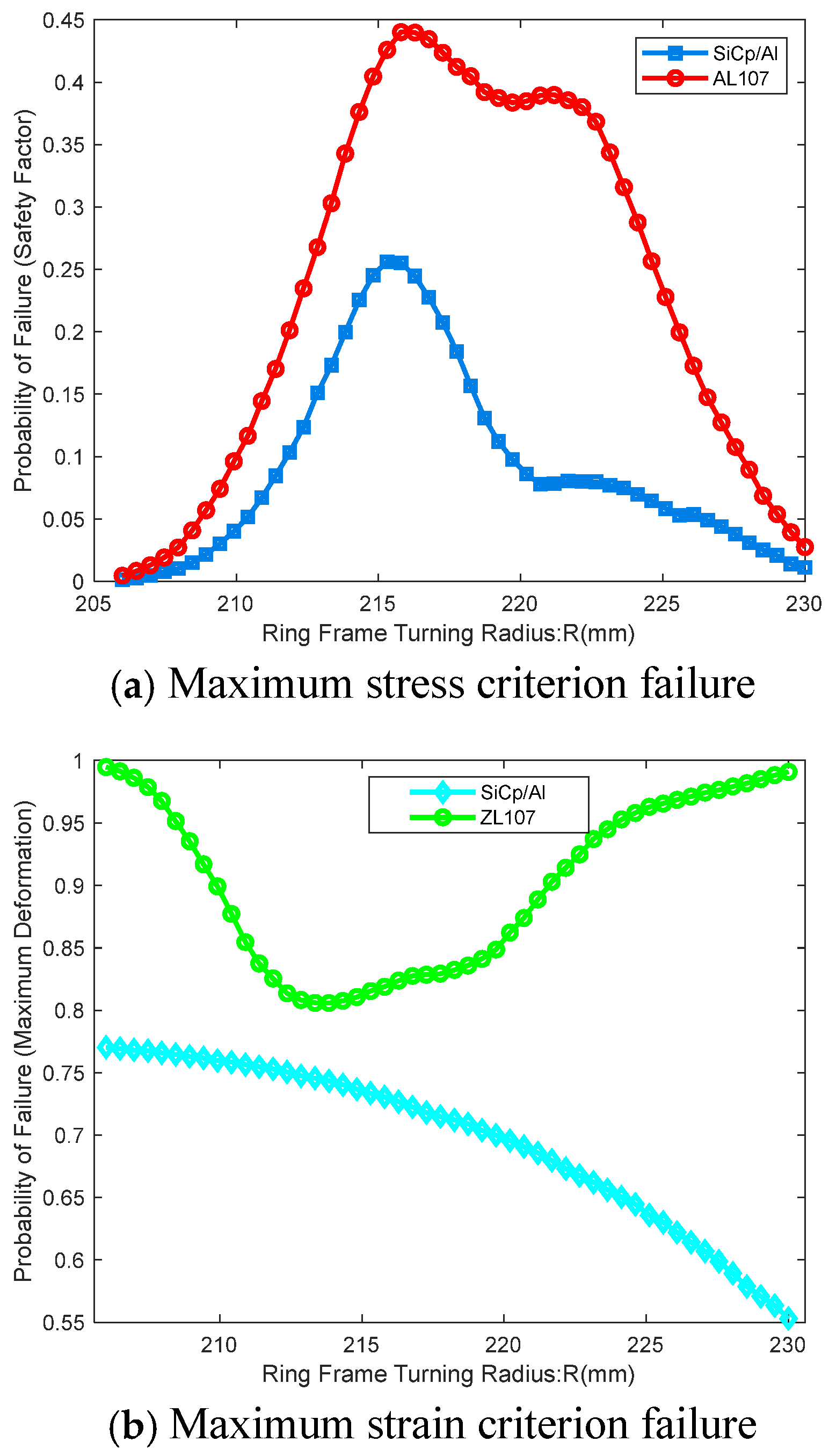
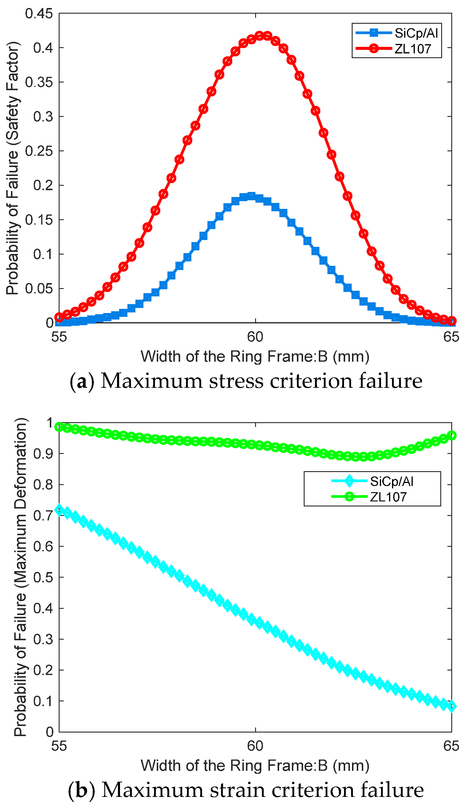
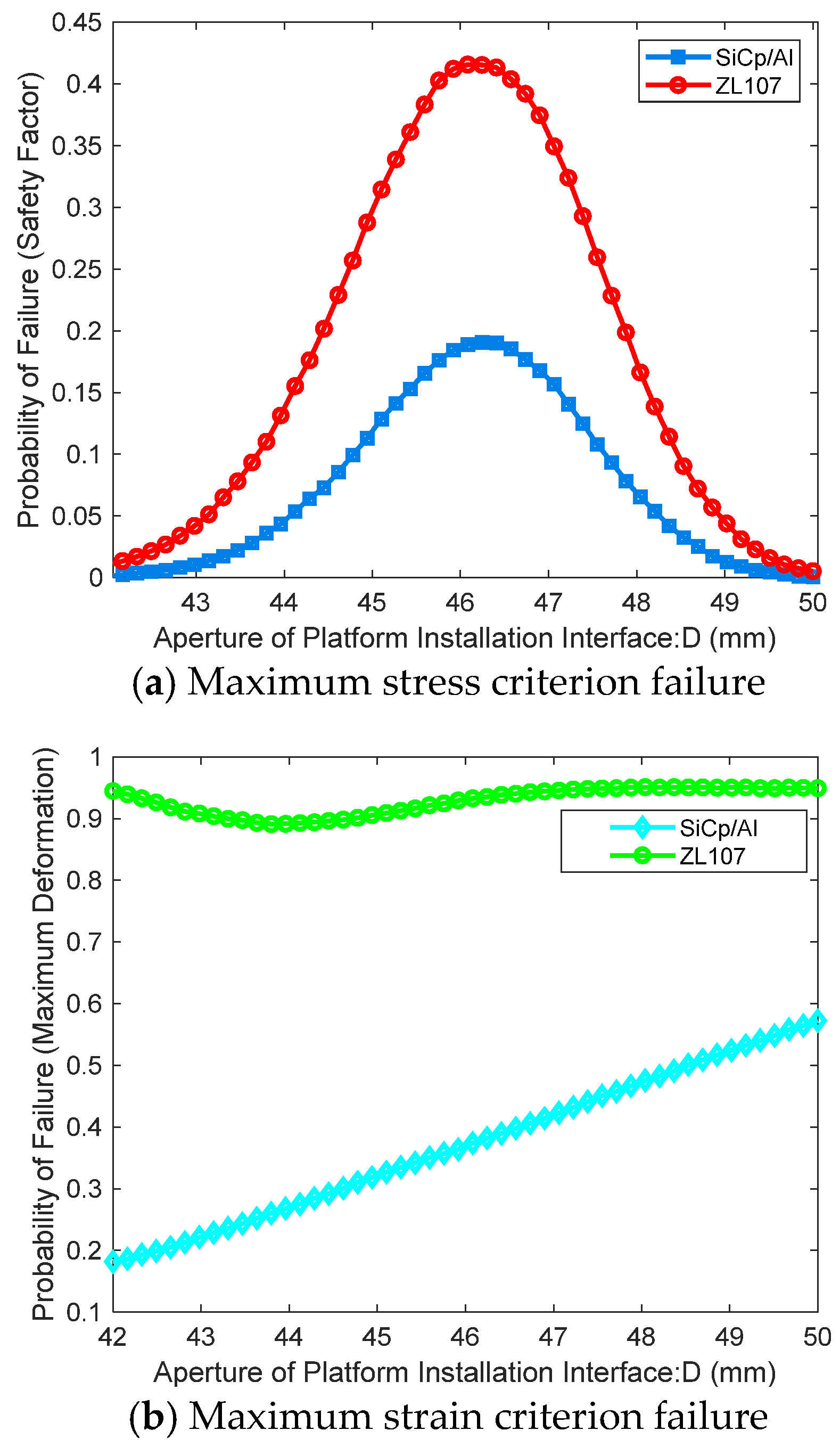
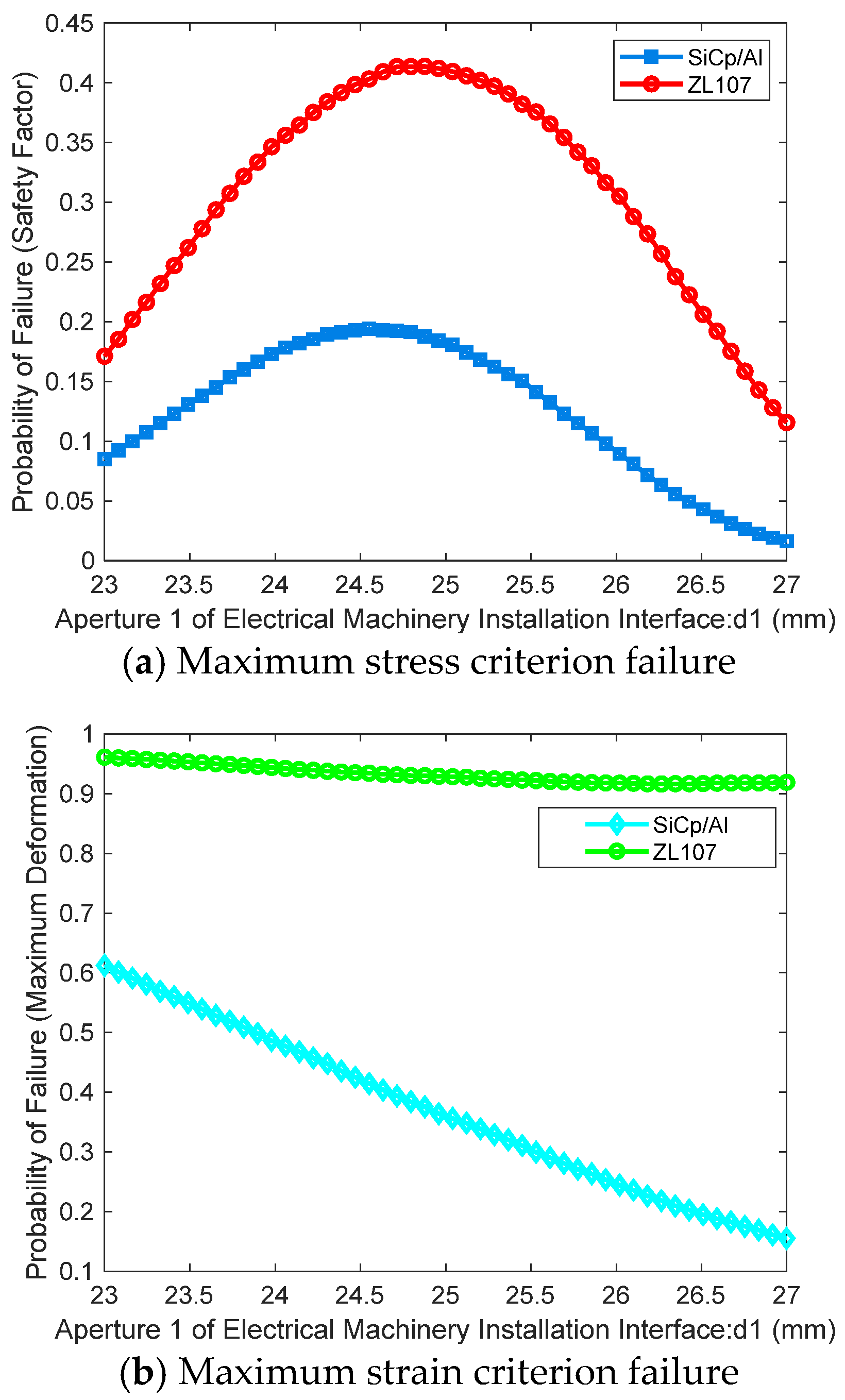
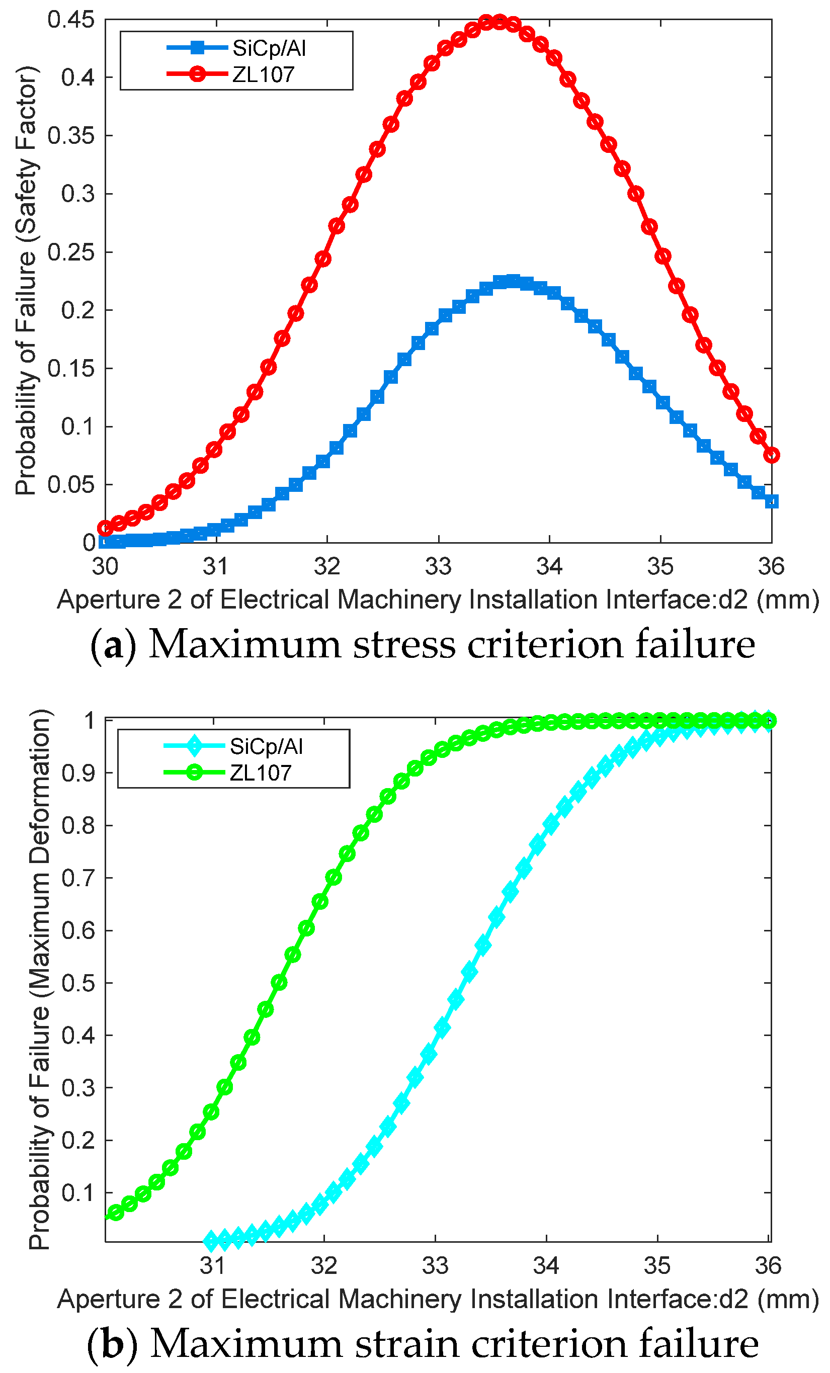
This paper considers the strength failure criterion as the failure criterion for the outer frame assembly structure under overload conditions, utilizing both the maximum stress criterion and the maximum strain criterion to determine whether the outer frame structure has failed. The maximum stress criterion states that material failure occurs when the maximum stress under the applied load reaches the material’s strength limit. The maximum strain criterion indicates that material failure occurs when the maximum strain under the applied load reaches the material’s strength limit.
In this paper, the maximum stress criterion is defined using the ratio of maximum stress to allowable stress as the safety factor (Failure Indicator 1). The maximum strain criterion uses the maximum strain of the structure under overload as Failure Indicator 2. Additionally, with the development and design of inertial measurement devices trending towards lightweight and miniaturization, mass is selected as a critical metric (Failure Indicator 3). The corresponding performance functions are denoted as g 4 x ,   g 5 x ,   g 6 x , where x = x 8 , x 9 , x 10 , x 11 , x 12 , x 13 .
The function corresponding to failure under the maximum stress criterion is Equation (17):
g 4 x = n F s t r e s s _ max n n e e d
The function corresponding to failure under the maximum strain criterion is Equation (18):
g 5 x = δ d e f o r m a t i o n _ max δ n e e d
The function corresponding to mass failure is Equation (19):
g 6 x = W q u a l i t y _ max W n e e d
Addressing the uncertainty in the parameters of the outer frame structure, this paper first separately considers the two failure modes: failure under the maximum stress criterion and failure under the maximum strain criterion. A comparative analysis of the performance of the outer frame structure using aluminum alloy and SiCp/Al composite materials is conducted, with the outer frame roundness R , thickness H , width B , platform mounting interface D , motor mounting interface 1 d 1 , and motor mounting interface 2 d 2 as inputs. As shown in 
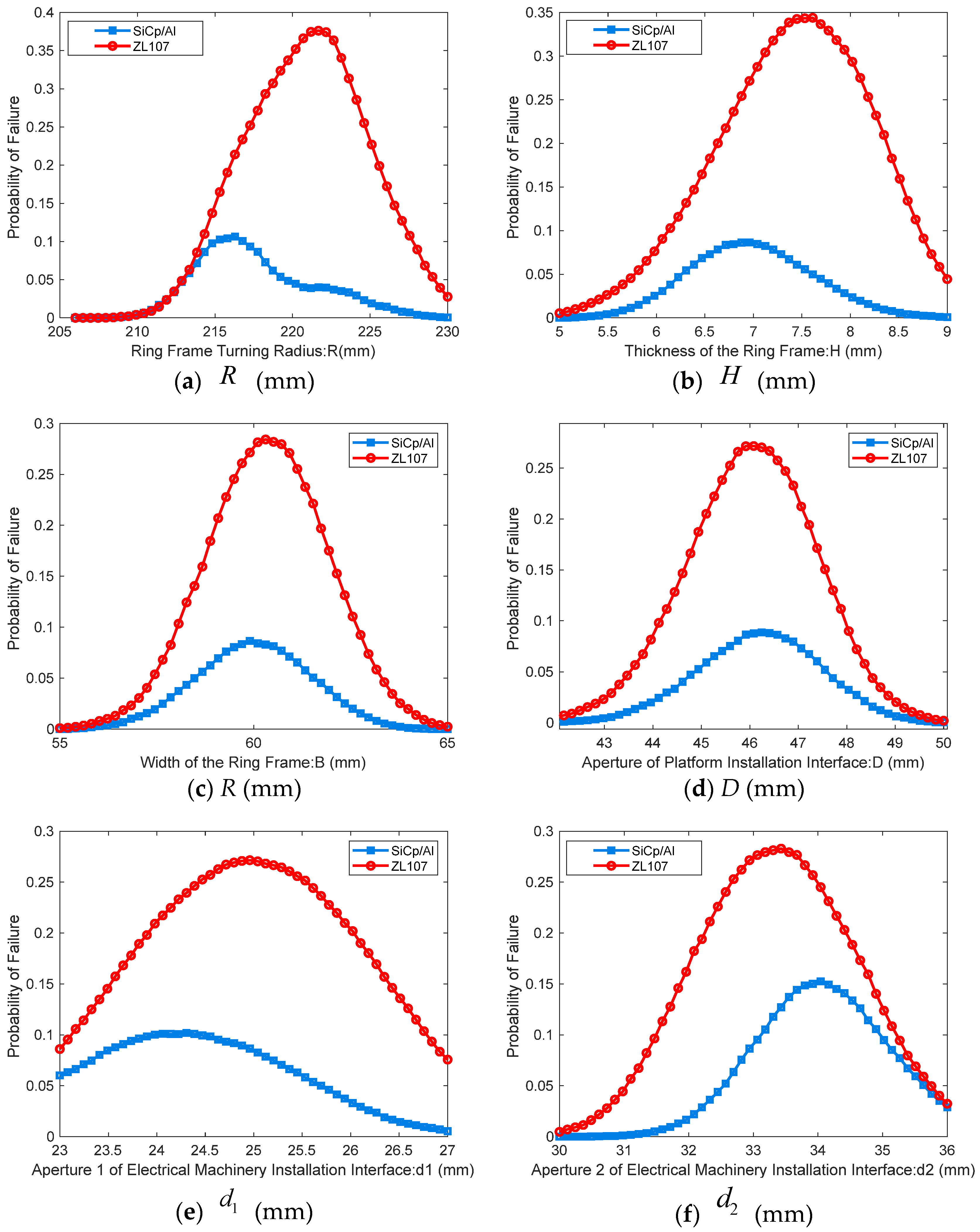
Figure 3, the outputs are the safety factor corresponding to the maximum stress and the maximum strain under mechanical overload conditions. A Kriging surrogate model is established to accurately predict these output indicators. Based on the Kriging surrogate model, the Sobol sequence sampling method is employed to simulate the random uncertainties of each design parameter and study their impact on failure probability under different failure modes.
Moreover, to comprehensively assess the performance of aluminum alloy and SiCp/Al materials, it is important to note that the occurrence of any one failure mode signifies the failure of the outer frame structure. Therefore, the three failure modes are treated as a series relationship, and the overall performance function can be expressed as Equation (20):
Z x = min g 1 x , g 2 x , g 3 x
If g x 0 , the mixed inertial navigation system experiences functional failure. The failure domain F for the mixed inertial navigation function can be expressed as Equation (21):
F = x : g x 0
The probability of failure P f representing the system output response falling within the failure probability (i.e., the failure domain F ) is provided by Equation (22):
P f = P x : x F

4. Reliability Analysis Methods

To address the uncertainty issues in the parameters of the mixed inertial navigation structure, this paper conducts an uncertainty analysis based on the failure probability reliability analysis model of the mixed inertial navigation system. First, a global sensitivity analysis method [33] based on failure probability is employed to analyze the reliability model focusing on navigation function failure. This approach yields global sensitivity indicators for each parameter concerning the system’s functional failure probability, allowing for the ranking of parameters based on their importance in influencing functional failure. Additionally, the Sobol sequence sampling method is used to simulate the dual random uncertainties in the outer frame structure parameters and investigate the uncertainty impact of these parameters on the probability of structural strength failure of the outer frame assembly. The reliability analysis workflow is illustrated in Figure 12.

4.1. Global Sensitivity Analysis Method Based on Mixed Inertial Navigation Function Failure

Assuming Y = g ( X ) is the functional equation of the system, and X = ( X 1 , X 2 , , X n ) represents the n-dimensional random design variables, its joint probability density function is denoted as f X ( x ) . For independent design variables, the joint probability density function can be expressed as f X ( x ) = i = 1 n f X i ( x i ) , where f X i ( x i ) is the marginal probability density function of the design variable X i . By definition, the system’s functional failure probability can be represented as Equation (23):
P { F } = F f X ( x ) d x = R n I F ( x ) f X ( x ) d x = E I F ( x )
where F = x : g ( x ) 0 indicates the system’s functional failure domain, and I F ( x ) represents the indicator function of the failure domain, where I F ( x ) = 1 if x F and I F ( x ) = 0 if x F , E [ ] denotes the expectation operator.
To analyze the impact of the uncertainty of design variable X i on the system’s functional failure probability, the conditional functional failure probability P { F | X i } is considered when X i is fixed. The definition of P { F | X i } is Equation (24):
P { F | X i } = P { F } f X i ( x i | F ) f X i ( x i )
where f X i ( x i | F ) indicates the conditional probability density function of the input variable X i when structural failure occurs. To obtain a standardized indicator, the global sensitivity indicator of the design variable X i with respect to the system’s functional failure probability can be defined as Equation (25):
δ i P { F } = 1 2 X i P { F } P { F | X i } f X i ( x i ) d x i = 1 2 X i P { F } P { F } f X i ( x i | F ) f X i ( x i ) f X i ( x i ) d x i = 1 2 P { F } X i f X i ( x i ) f X i ( x i | F ) d x i
From Equation (21), it is clear that to estimate δ i P { F } , one only needs to estimate the structural failure probability P { F } and the conditional probability density function f X i ( x i | F ) of the input variables under structural failure conditions. For this, a sample set can be used to estimate P { F } while employing the failure samples to estimate f X i ( x i | F ) , leading to the following estimation process for δ i P { F } .
Generate a sample set { x ( 1 ) , x ( 2 ) , , x ( N ) } from the joint probability density function f X ( x ) to estimate the structural failure probability P ( F ) , which is defined as Equation (26):
P ^ { F } = 1 N j = 1 N I F ( x ( j ) ) = N F N
where N F is the number of failure samples.
From N samples, select the failure samples { x F ( 1 ) , x F ( 2 ) , , x F ( N F ) } to estimate the conditional probability density function of all input variables X i ( i = 1 , , n ), denoting the results as f ^ X i ( x i | F ) ( i = 1 , , n ).
The estimate of δ i P { F } ( i = 1 , , n ) can then be calculated as follows Equation (27):
δ ^ i P { F } = 1 2 P ^ { F } X i f X i ( x i ) f ^ X i ( x i | F ) d x i

4.2. Dual Random Uncertainty Analysis Method for Structural Strength Failure of the Outer Frame Component

This paper introduces uncertainty analysis into the study of structural strength failure of the outer frame component, employing the Sobol sequence sampling method to simulate the dual random phenomena of each parameter in the outer frame structure during production and operation. The specific research methods are shown in Figure 12 [34].

5. Calculation Results and Analysis

5.1. Global Sensitivity Analysis Based on Mixed Inertial Navigation Function Failure

Based on Figure 10 and the Kriging surrogate model, a comparative analysis of the predicted and actual rotation angles of the hybrid inertial navigation system’s X, Y, and Z three-axis coordinate systems deviating from the virtual body coordinate system due to elastic displacement of structural components under impact overload conditions was obtained. Figure 13 shows that the error between the predicted and actual values based on the Kriging surrogate model is within the allowable range, verifying the reliability and stability of the prediction model.
Using the global sensitivity analysis based on Bayesian formulas introduced in Section 4.1, the failure probability of the mixed inertial navigation function is analyzed. This analysis yields global sensitivity indicators for various parameters affecting the system’s failure probability. To clearly compare the magnitudes of the global sensitivity indicators for each parameter, the corresponding bar chart is presented, with results shown in Table 7 and Figure 14. To verify the validity and reasonableness of the analysis results, a global sensitivity analysis of the model based on the traditional Monte Carlo simulation method, as referenced in [29], was conducted, with the computation results displayed in Table 7 and Figure 15.
The results of sensitivity analysis usually depend on the sampling process of numerical calculation methods. If the sample size is insufficient, the sensitivity index may deviate or fluctuate. By changing the sample size N, the trend of the global sensitivity index of the design variables with respect to the sample size N can be determined, thereby evaluating whether the sensitivity index values of each design variable converge and further verifying the stability and reliability of the global sensitivity index calculation. The analysis results are shown in Figure 16.
According to Table 7 and the global sensitivity indicators calculated in Figure 14 and Figure 15, the importance measures of structural design parameters and material performance parameters on the functional failure probability of the hybrid inertial navigation system are presented. The importance ranking of each parameter obtained from the global sensitivity analysis based on the Bayesian formula is: H I n n e r   F r a m e > E I n n e r   F r a m e > H O u t e r   F r a m e > W O u t e r   F r a m e > W I n n e r   F r a m e > E F o u n a t i o n   S u p p o r t > E O u t e r   F r a m e . While the ranking obtained from the Monte Carlo method is the same: H I n n e r   F r a m e > E I n n e r   F r a m e > H O u t e r   F r a m e > W O u t e r   F r a m e > W I n n e r   F r a m e > E F o u n a t i o n   S u p p o r t > E O u t e r   F r a m e . The consistency of the importance ranking results from both methods indicates that the global sensitivity analysis method based on the Bayesian formula can effectively identify the relative importance of parameters. Among these, the uncertainties of parameters H I n n e r   F r a m e , E I n n e r   F r a m e , and H O u t e r   F r a m e have the most significant impact on the functional failure probability of hybrid inertial navigation, followed by W O u t e r   F r a m e and W I n n e r   F r a m e , which have a relatively minor effect, while the uncertainties of parameters E F o u n a t i o n   S u p p o r t and E O u t e r   F r a m e have the least impact on the system’s functional failure probability.
However, it should be noted that the global sensitivity analysis method based on the Bayesian formula and the global sensitivity analysis method based on the Monte Carlo method only obtain the consistency of the sensitivity index ranking of the two design variables. Due to the differences in theoretical basis and calculation process between the two methods, this analysis is only preliminary.
From Figure 16, it can be seen that as the sample size increases, the global sensitivity indicators of design variables on the functional failure of hybrid inertial navigation tend toward a constant value, indicating that the proposed global sensitivity analysis method based on the Bayesian formula is convergent.

5.2. Dual Random Uncertainty Analysis of Outer Frame Component Based on Structural Strength Failure

5.2.1. Impact of Design Parameters on Failure Probability Under Single Failure Mode

The threshold ranges for various failure modes considered in this study are shown in Table 6. Figure 17, Figure 18, Figure 19, Figure 20, Figure 21 and Figure 22 present the failure probabilities of the SiCp/Al and ZL107 aluminum alloy outer frame structures under two failure modes, illustrating how these probabilities change with respect to the outer frame roundness R , outer frame thickness H, outer frame width B, platform installation interface D, motor installation interface 1 d1, and motor installation interface 2 d2.
As seen in Figure 17a, Figure 18a, Figure 19a, Figure 20a, Figure 21a and Figure 22a, with the gradual increase in design parameters, the failure probability under the maximum stress criterion for both composite materials initially increases and then decreases, exhibiting a maximum value. The failure probability for SiCp/Al composite material is significantly lower than that of ZL107 aluminum alloy; specifically, the failure probability for the ZL107 material is 44.77%, while for the SiCp/Al composite, it is 25.62%. In Figure 17b, Figure 18b, Figure 19b, Figure 20b, Figure 21b and Figure 22b, as the design parameters increase, the failure probabilities under the maximum strain criterion for both composite materials display different trends. Overall, the SiCp/Al composite material demonstrates a significant reduction in failure probability compared to traditional ZL107 material under the maximum strain criterion, indicating a notable enhancement in the reliability performance of the outer frame structure. It can effectively resist deformation under high overload conditions.

5.2.2. Impact of Design Parameters on Failure Probability When Considering Series of Failure Modes

When considering three failure modes in series, the failure probabilities of each design parameter for both composite materials at specified thresholds are illustrated in Figure 23a–f. The results indicate that the overall failure probability of the structure also follows a trend of “initial increase followed by decrease”, exhibiting a maximum value. Specifically, the maximum failure probability for the ZL107 traditional material is approximately 37.6%, while for the SiCp/Al composite material, it is about 15.26%. The failure probability for SiCp/Al in series with three failure modes is significantly lower than that for the ZL107 material, reflecting its excellent reliability.
It is expected that the reliability analysis results of the outer frame structure considering three failure modes in series will differ from those considering a single failure mode. Additionally, the influence of each failure mode on the reliability of the outer frame structure varies, necessitating further research.

6. Experimental Verification and Analysis

This article selects the optimal design size for each design parameter based on the actual envelope size for part processing and forming, and carries out the assembly and debugging of the inertial navigation system combination. We installed the hybrid laser inertial navigation system on the fixture and semi sine impact test bench, and conducted experimental verification according to Table 2.

Analysis of Ground Test Results

The half sine impact test bench, based on the test input conditions in Table 2 and the output response on the platform, is shown in Figure 24, Figure 25 and Figure 26.
According to the input conditions in Figure 24a, Figure 25a and Figure 26a, a half sine impulse test was conducted. Data were collected based on the output of the laser gyroscope signal from the hybrid inertial measurement system and the angle measurement sensors of the inner and outer frames. The X, Y, and Z test data are shown in Table 8 below.
According to Table 8, it can be seen that during the impact tests conducted on the product in the X, Y, and Z directions, the laser gyroscope worked normally, the hybrid laser system function was normal, and the angular velocity change of the platform corresponding to each impact direction was less than 12 ″/s. The maximum angle change of the inner and outer frames was 0.107°, indicating that the system structure has the ability to withstand large overloads and mechanical environments under a high number of levels, and has good environmental adaptability and reliability.

7. Conclusions

This study analyzed the uncertainty of a novel hybrid laser inertial navigation system that fails during high-dynamics, long-duration operations. First, mechanical simulation models (rotational modulation structure with angular motion isolation and outer frame component) were established to analyze key components’ mechanical properties under high overloads with different composites. Then, taking the deviation of the inertial navigation coordinate system from the virtual inertial group coordinate system under impact overload as the navigation failure criterion, a Kriging-based reliability analysis model for hybrid inertial navigation function failure was set up. Furthermore, considering the outer frame component’s structural strength failure criterion under overload, a Kriging-based reliability analysis model for its structural failure was developed. Global sensitivity analysis (based on the Bayesian formula) and uncertainty analysis (based on Sobol sequence sampling) were used. Finally, experimental verification was conducted, and the following conclusions were drawn:
  • Modal analysis shows that structural components made of SiCp/Al composite have significantly higher dynamic frequencies than those made of ZL107 material, highlighting the boost in dynamic frequency with stiffer materials. Under 120 g, 11 ms half-sine impacts, SiCp/Al in the hybrid inertial navigation system deforms less, being less prone to plastic failure, more overload-resistant than ZL107, and ensuring better safety.
  • Bayesian-based global sensitivity analysis (sample size N1 = 5 × 10⁵) indicates that inner frame thickness, inner frame material strength, and outer frame thickness most significantly impact the hybrid inertial navigation function’s failure probability (sensitivities: =0.01657, =0.00873, =0.00818). Kriging-model-based, dual-random uncertainty analysis of the outer frame shows that its multi-mode failure probability follows an “increase-then-decrease” trend. SiCp/Al has a much lower failure probability than ZL107, confirming its high-overload deformation resistance and reliability, useful for hybrid inertial group reliability design.
  • Within the size envelope range, the optimal design parameters were selected to design and machine form each part. After assembling and debugging the entire machine, impact tests were conducted on the product in the X, Y, and Z directions. The tests showed that the laser gyroscope worked normally, the hybrid laser system function was normal, and the platform angular velocity change corresponding to each impact direction was less than 12 ″/s. The maximum angle change of the inner and outer frames was 0.107°, indicating that the system structure can withstand large overloads and multiple levels of mechanical environments and has good environmental adaptability and reliability.
  • Within the field of the design of hybrid inertial navigation structures, this paper studies the optimization of material distribution and geometric dimensions through parametric design and analysis, significantly reducing stress concentration phenomena. Simultaneously using high-performance composite materials can improve the strength, stiffness, and fatigue life of the structure and better meet the design requirements for lightweight and compact product design. At the same time, this significantly improves the stability of the structure and reduces the impact of external large-scale mechanical environments on the navigation system. The proposed structure can provide a more stable installation reference surface for inertial navigation systems, significantly improving navigation accuracy, especially in long-term and high-dynamic environments. Therefore, high-strength and high elastic modulus materials should be prioritized to achieve better performance in high-overload and dynamic environments. At the same time, one must pay attention to the internal and external framework’s structural parameters to ensure appropriate spatial dimensions that are close to the optimal value in order to improve the high-dynamic and long-term reliability of the system in vertical navigation. The method used in this study can be applied to other inertial measurement equipment components and systems to provide reliable design support.

8. Outlook

  • Conduct a mixed subjective and objective uncertainty analysis, distinguish the uncertainty characterization methods of design variables, and fully explore the impact of design parameter uncertainty on the overall reliability indicators of the system;
  • Identify other failure modes and conduct reliability analysis of hybrid laser inertial navigation from the perspective of system reliability.

Author Contributions

Conceptualization, B.Z., C.H. and X.W.; Methodology, B.Z., X.W., J.W. and J.Z.; Software, B.Z., X.W., Q.D., X.L. and F.Z.; Validation, B.Z., C.H., J.W. and J.Z.; Formal analysis, B.Z. and X.W.; Investigation, B.Z. and C.H.; Resources, C.H., J.W. and J.Z.; Data curation, B.Z. and X.W.; Writing—original draft, B.Z., C.H., X.W., J.W. and J.Z.; Writing—review & editing, C.H., Q.D., X.L. and F.Z.; Visualization, B.Z. and X.W.; Supervision, C.H., J.W., J.Z., Q.D., X.L. and F.Z.; Project administration, C.H.; Funding acquisition, C.H., J.W. and J.Z. All authors have read and agreed to the published version of the manuscript.

Funding

National Natural Science Foundation of China for its general project on the prediction method of remaining life of highly heterogeneous inertial measurement devices under limited data (62373368) and the National Natural Science Foundation of China for its major research instrument development project on the integration of health management microsystems for key equipment of reusable launch vehicles (62227814).

Institutional Review Board Statement

Not applicable.

Informed Consent Statement

Not applicable.

Data Availability Statement

The original contributions presented in this study are included in the article. Further inquiries can be directed to the corresponding author.

Conflicts of Interest

The authors declare no conflict of interest.

References

  1. Xu, Y.; Liu, S.; He, C.; Wu, H.; Cheng, L.; Yan, G.; Huang, Q. Reliability of MEMS inertial devices in mechanical and thermal environments: A review. Heliyon 2024, 10, 27481. [Google Scholar] [CrossRef] [PubMed]
  2. Hu, P.; Yang, A.; Zhang, R.; Li, D.; Tan, W.; Wu, Q.; Xu, P. Time-variant harmonic model, modulated sliding discrete Fourier transform, and Kalman filter-based time–frequency domain fusion for fast self-calibration of the installation errors of rotational inertial navigation systems. Mech. Syst. Signal Process. 2024, 219, 111573. [Google Scholar] [CrossRef]
  3. Cheng, D.; Liu, C.; Gao, G.; Wang, J.; Yan, F. Modeling and analysis of dynamic cone error in laser strapdown inertial navigation system. Trans. Nanjing Univ. Aeronaut. Astronaut. 2023, 40, 641–652. (In English) [Google Scholar] [CrossRef]
  4. Qi, F.; Chen, G.; Zhao, X.; Wang, X. A high-precision positioning method for shield tunneling based on dual-axis hybrid inertial navigation system. Measurement 2024, 224, 113915. [Google Scholar]
  5. Zhang, C.; Zhou, Z.; Ning, P.; Ming, Z.; Zhang, C.; Fang, L. IBRNet: Interpretable Belief Rule Network modeling method for fault diagnosis of redundant inertial navigation systems. Control. Eng. Pract. 2024, 144, 105822. [Google Scholar] [CrossRef]
  6. Zhao, S.; Guo, C.; Ke, C.; Zhou, Y.; Shu, X. Temperature drift compensation of fiber strapdown inertial navigation system based on GSA-SVR. Measurement 2022, 195, 111117. [Google Scholar] [CrossRef]
  7. Feng, P.D. On hybrid inertial navigation systems. J. Chin. Inert. Technol. 2016, 24, 281–285. [Google Scholar]
  8. Liu, Z.; Wang, L.; Li, K.; Gao, J. A compensation method of lever arm effect for tri-axis hybrid inertial navigation system based on fiber opticgyro. Meas. Sci. Technol. 2017, 28, 055103. [Google Scholar] [CrossRef]
  9. Song, L.; Xue, L.; Dong, Y.; Zhao, W.; Chen, X. Review and Prospect of Inertial Technology Development Process. Navig. Control. 2021, 20, 29–36. [Google Scholar]
  10. Liu, Z.; Xu, F.; Wang, T. Structural dynamics simulation analysis of integrated small inertial navigation platform system. Navig. Control. 2013, 12, 23–28. [Google Scholar]
  11. Feng, P.D.; Li, K.; Wang, W. New initial alignment method of carrier based inertial navigation system on swinging base. Chin. J. Sci. Instrum. 2012, 33, 1–6. [Google Scholar]
  12. Ma, H.; Wu, J. Analysis of positioning errors caused by platform vibration of airborne LiDAR system. In Proceedings of the 8th IEEE International Symposium on Instrumentation and Control Technology, London, UK, 11–13 July 2012; pp. 257–261. [Google Scholar]
  13. Zhai, Y.; Feng, P. Research on the influence of platform angular vibration on inertial navigation system error under vibration conditions. J. Chin. Inert. Technol. 2000, 2, 2–7. [Google Scholar] [CrossRef]
  14. Huang, T.; Duan, H.; Hu, T.; Huang, B.; Yuan, W. Analysis of static and dynamic characteristics and structural optimization of inertial navigation external frame. Mech. Electr. Eng. Technol. 2018, 47, 135–139. [Google Scholar]
  15. Zhang, S.; Shi, X.; Yang, P.; Wang, L.; Chang, B. Research on the application of high performance aluminum-lithium alloy in three-inertial group. Aviat. Precis. Manuf. Technol. 2023, 59, 34–36. [Google Scholar]
  16. Couvertier, M.; Pacher, L.; Fradet, L. Does IMU redundancy improve multi-body optimization results to obtain lower-body kinematics? A preliminary study says no. J. Biomech. 2024, 168, 112091. [Google Scholar]
  17. Georgantzia, E.; Gkantou, M.; Kamaris, G.S. Aluminium alloys as structural material: A review of research. Eng. Struct. 2021, 227, 11372. [Google Scholar]
  18. Deepati, A.K.; Alhazmi, W.; Benjeer, I. Mechanical characterization of AA5083 aluminum alloy welded using resistance spot welding for the lightweight automobile body fabrication. Mater. Today Proc. 2021, 45, 5139–5148. [Google Scholar]
  19. Cao, L.; Chen, B.; Guo, B.S. A review of carbon nanotube is persion methods in carbon nanotube reinforced aluminium matrix composites manufacturing process. J. Netshape Form. Eng. 2021, 13, 9–24. [Google Scholar]
  20. Chak, V.; Chattopadhyay, H.; Dora, T.L. A review on fabrication methods, reinforcements and mechanical properties of aluminum matrix composites. J. Manuf. Process. 2020, 56, 1059–1074. [Google Scholar]
  21. Kumar, P.L.; Lombardi, A.; Byczynski, G.; Murty, S.N.; Murty, B.; Bichler, L. Recent advances in aluminium matrix composites reinforced with graphene-based nanomaterial: A critical review. Prog. Mater. Sci. 2022, 128, 100948. [Google Scholar]
  22. Pan, C.; Li, Z.; Zhang, Q.; Soja, B.; Gao, J. Smartphone-based Vision/MEMS-IMU/GNSS tightly coupled seamless positioning using factor graph optimization. Measurement 2024, 229, 114420. [Google Scholar]
  23. Duan, Z.; Liu, Y.; Jin, H.; Yan, J.; Zhu, J. Concurrent multi-scale design optimization of fiber-reinforced composite material based on an adaptive normal distribution fiber optimization scheme for minimum structural compliance and additive manufacturing. Comput. Methods Appl. Mech. Eng. 2025, 434, 117596. [Google Scholar]
  24. Zhang, F.; Qiao, Z.; Tian, Y.; Wu, M.; Xu, X. Reliability Analysis of Complex Structures Under Multi-Failure Mode Utilizing an Adaptive AdaBoost Algorithm. Appl. Sci. 2024, 14, 10098. [Google Scholar] [CrossRef]
  25. Hu, W.; Yan, J.; Shi, Q.; Fang, H.; Liu, Y. Reliability analysis of liquid rocket engines using adaptive kriging. Aerosp. Control. 2022, 40, 50–56. [Google Scholar] [CrossRef]
  26. Luo, C.; Zhu, S.-P.; Keshtegar, B.; Macek, W.; Branco, R.; Meng, D. Active Kriging-based conjugate first-order reliability method for highly efficient structural reliability analysis using resample strategy. Comput. Methods Appl. Mech. Eng. 2024, 423, 116863. [Google Scholar]
  27. Huang, X.; Li, Y.; Zhang, Y.; Zhang, X. A new direct second-order reliability analysis method. Appl. Math. Model. 2018, 55, 68–80. [Google Scholar]
  28. Zhang, H.; Han, L.; Zhong, B.; Cheng, L.; Xu, L.; Shen, H.; Li, J. Research on Monte Carlo simulation method for thick pinhole imaging. Fusion Eng. Des. 2023, 194, 113904. [Google Scholar]
  29. Guerra, J.; Velásquez, L.; Rubio-Clemente, A.; Jaramillo, L.; Chica, E. Design and optimization of a siphon turbine using the response surface methodology. Results Eng. 2024, 22, 102241. [Google Scholar]
  30. Yan, B.; Zhong, Z.; Bai, B. A convolutional neural network-based proxy model for field production prediction and history matching. Gas Sci. Eng. 2024, 122, 205219. [Google Scholar]
  31. Xu, C.-Z.; Han, Z.-H.; Zan, B.-W.; Zhang, K.-S.; Chen, G.; Wang, W.-Z. Expert’s experience-informed hierarchical kriging method for aerodynamic data modeling. Eng. Appl. Artif. Intell. 2024, 133, 108490. [Google Scholar]
  32. Zhou, C.; Ji, M.; Zhang, Y.; Liu, C.; Zhao, D. Research on reliability and sensitivity of landing gear mechanism under multiple failure modes. J. Northwestern Polytech. Univ. 2021, 39, 46–54. [Google Scholar] [CrossRef]
  33. Zhou, S.; Lv, Z.; Ling, C. Meta IS-AK algorithm for solving global sensitivity of reliability. Acta Aeronaut. Sin. 2020, 41, 169–178. [Google Scholar]
  34. Zhang, F.; Cheng, L.; Wu, M.; Xu, X.; Wang, P.; Liu, Z. Performance analysis of two-stage thermoelectric generator model based on Latin hypercube sampling. Energy Convers. Manag. 2020, 221, 11315. [Google Scholar] [CrossRef]
  35. Zhang, F.; Wang, X.; Wang, W.; Zhang, J.; Du, R.; Li, B.; Liu, W. Uncertainty analysis of photovoltaic cells to determine probability of functional failure. Appl. Energy 2023, 332, 120495. [Google Scholar] [CrossRef]
Figure 1. System principle diagram of hybrid INS measurement unit.
Applsci 15 03724 g001
Figure 2. Hybrid INS structural model diagram. 1: Base assembly; 2: Inner frame; 3: Rotation locking system; 4: Outer frame assembly; 5: Platform assembly; 6: Damper assembly.
Applsci 15 03724 g002
Figure 3. Outer frame assembly model diagram. 1: Shaft end encoder assembly; 2: Outer frame; 3: Platform simulation counterweight; 4: Shaft end motor assembly.
Applsci 15 03724 g003
Figure 4. Outer frame model simplification.
Applsci 15 03724 g004
Figure 5. Shaft-end component model simplification.
Applsci 15 03724 g005
Figure 6. Contact setting of screw and shaft end assembly.
Applsci 15 03724 g006
Figure 7. Internal finite element mesh of the hybrid laser INS structure.
Applsci 15 03724 g007
Figure 8. Semi-sine shock pulse waveform and tolerance.
Applsci 15 03724 g008
Figure 9. Installation of the inertial group on the missile. Note: Projectile coordinate system: o x b y b z b Inertial group virtual body coordinate system: o x b t 0 y b t 0 z b t 0 Inertial group body coordinate system: o x b t y b t z b t .
Applsci 15 03724 g009
Figure 10. Construction of hybrid inertial navigation kriging proxy model.
Applsci 15 03724 g010
Figure 11. Structural design parameters of the outer frame.
Applsci 15 03724 g011
Figure 12. Calculation process of hybrid inertial navigation reliability analysis based on failure probability.
Applsci 15 03724 g012
Figure 13. Comparison of actual values and predicted values based on the Kriging surrogate model.
Applsci 15 03724 g013
Figure 14. Bar chart of global sensitivity calculation results based on Bayesian formula.
Applsci 15 03724 g014
Figure 15. Bar chart of global sensitivity calculation results based on Monte Carlo method.
Applsci 15 03724 g015
Figure 16. Variation in sensitivity indicators with sample size. (a): Variable X4, X6 (b): Variable X1, X2, X3, X5, X7.
Applsci 15 03724 g016
Figure 17. Variation in failure probability with outer frame roundness R .
Applsci 15 03724 g017
Figure 18. Variation in failure probability with outer frame thickness H.
Applsci 15 03724 g018
Figure 19. Variation in failure probability with outer frame width B.
Applsci 15 03724 g019
Figure 20. Variation in failure probability with platform installation interface D.
Applsci 15 03724 g020
Figure 21. Variation of failure probability with motor installation interface 1 d1.
Applsci 15 03724 g021
Figure 22. Variation in failure probability with motor installation interface 2 d2.
Applsci 15 03724 g022
Figure 23. Impact of design parameters on failure probability under series failure modes.
Applsci 15 03724 g023
Figure 24. (a). X-direction impact input. (b). X-direction impact table body response output. The Chinese character “时域” in the picture means time domain.
Applsci 15 03724 g024
Figure 25. (a). Y-direction impact input. (b). Y-direction impact table body response output. The Chinese character “时域” in the picture means time domain.
Applsci 15 03724 g025aApplsci 15 03724 g025b
Figure 26. (a). Z-direction impact input. (b). Z-direction impact table body response output. The Chinese character “时域” in the picture means time domain.
Applsci 15 03724 g026
Table 1. Comparison of SiCp/Al Composites with other common materials.
Performance IndicatorsSiCp/AlZL107Mg/AlStainless Steel
Density/(g/cm3)2.92.681.87.9
Coefficient of thermal expansion11–1321.426.116.6
Elastic modulus/Gpa145–1507740–45184
Tensile strength at break/Mpa>530>220>150>520
Yield strength/Mpa>420>180140–245275
Table 2. Semi-sine shock test conditions.
ProjectPeak Acceleration ADurationLoading Direction
Half sine wave shock120 g4 msX\Y\Z
Table 3. Comparison of FEA results for aluminum alloy and SiCp/Al composites.
ProjectZL107 MaterialSiCp/Al MaterialRate of Change (%)
Free modal analysis of the platform1st natural frequency/Hz3774.44336.714.90
2nd natural frequency/Hz4719.5408.914.62
Free modal analysis of inner frame1st natural frequency/Hz614.65676.3510.04
2nd natural frequency/Hz746.78836.5312.02
Free modal analysis of outer frame1st natural frequency/Hz439.65487.8510.96
2nd natural frequency/Hz514.35587.4414.21
Free modal analysis of foundation1st natural frequency/Hz383.35424.10.60
2nd natural frequency/Hz407.67452.6111.02
Half-sine shock analysisPlatform120 g impact maximum displacement/mm0.342520.32978−3.72
Inner frame0.03910.03331−14.81
Outer frame0.038010.0324−14.76
Foundation0.026040.0233−10.52
PlatformSafety factor corresponding to the maximum stress of 120 g impact2.13.252.4
Inner frame1.62.556.3
Outer frame1.42.364.2
Foundation1.82.961.1
Table 4. Distribution of mixed inertial navigation structural size parameters and material performance parameters.
Parameter NameMarkUnitMean Value μ X i Standard Deviation σ X i Distribution Type
E O u t e r   F r a m e X 1 Pa7.8 × 101015.6 × 109Normal distribution
E I n n e r   F r a m e X 2 Pa7.8 × 101015.6 × 109Normal distribution
E F o u n a t i o n   S u p p o r t X 3 Pa5.9 × 101011.8 × 109Normal distribution
H O u t e r   F r a m e X 4 mm7.000.14Normal distribution
W O u t e r   F r a m e X 5 mm60.001.20Normal distribution
H I n n e r   F r a m e X 6 mm7.900.16Normal distribution
W I n n e r   F r a m e X 7 mm65.001.30Normal distribution
Table 5. Distribution information of random variables in the outer frame structure.
Parameter NameMarkUnitMean Value μ X i Standard Deviation σ X i Distribution Type
Outer frame roundne R X 8 mm218.004.36Normal distribution
Outer frame thicknes H X 9 mm7.000.14Normal distribution
Outer frame width B X 10 mm60.001.20Normal distribution
Platform installation interface D X 11 mm46.000.92Normal distribution
Motor mounting interface 1 d 1 X 12 mm25.000.50Normal distribution
Motor mounting interface 2 d 2 X 13 mm33.000.66Normal distribution
Table 6. Related data for mixed inertial navigation function failure.
Failure IndicatorsFailure Boundary
θ X * ≤12″
θ Y * ≤12″
θ Z * ≤12″
n n e e d ≥2.0
δ n e e d ≥0.052 mm
W n e e d ≥0.8 kg
Table 7. Global sensitivity indicators of each parameter on system functional failure probability.
Method δ 1 P { F } δ 2 P { F } δ 3 P { F } δ 4 P { F } δ 5 P { F } δ 6 P { F } δ 7 P { F } Sample Size
Bayesian0.00329 0.00873 0.00381 0.00818 0.00518 0.01657 0.004265 × 10⁴
Monte Carlo [35]0.00096 0.00177 0.00089 0.00171 0.00104 0.00662 0.000995 × 10⁴
Table 8. Data output of inertial measurement system for three-way impact test.
Gyroscope Output (°/s)Angular Velocity of the Platform (°/s)Inner Frame Variation (°)Outer Frame Variation (°)
XYZXYZBefore and After ImpactBefore and After Impact
X impact4.843.864.25.522.8400.0110.035
Y impact21.318.444.910.510.6270.0060.03
Z impact42445.936.632.15.90.1070.027
Disclaimer/Publisher’s Note: The statements, opinions and data contained in all publications are solely those of the individual author(s) and contributor(s) and not of MDPI and/or the editor(s). MDPI and/or the editor(s) disclaim responsibility for any injury to people or property resulting from any ideas, methods, instructions or products referred to in the content.

