Article

Optimizing Screw Fixation in Total Hip Arthroplasty: A Deep Learning and Finite Element Analysis Approach

1
Department of Mechanical Engineering, University of Texas at Tyler, Tyler, TX 75799, USA
2
California Health Sciences University College of Osteopathic Medicine, Clovis, CA 93611, USA
3
Department of Orthopaedic Surgery, University of California-Davis, Sacramento, CA 95817, USA
*
Author to whom correspondence should be addressed.
Appl. Sci. 2025, 15(7), 3722; https://doi.org/10.3390/app15073722
Submission received: 26 February 2025 / Revised: 19 March 2025 / Accepted: 25 March 2025 / Published: 28 March 2025

Abstract

:
Total hip arthroplasty (THA) is a widely performed procedure to restore hip function in patients with degenerative joint diseases. Traditional “press-fit” fixation methods rely on sufficient bone quality for stability, but additional screw fixation is often necessary for patients with suboptimal bone conditions. However, comprehensive studies utilizing predictive modeling to optimize screw placement strategies in THA remain limited. This study integrates finite element analysis (FEA) with deep learning (DL) to optimize screw fixation strategies, enhancing implant stability and reducing revision rates. The design optimization process was conducted to refine key implant parameters before training the deep learning surrogate model. By utilizing advanced simulation techniques—including Goodness of Fit analysis, Response Graphs, Local Sensitivity Analysis, and Spider Charts—critical factors influencing stress distribution and fixation stability were identified. The optimization process ensured that the dataset used for deep learning training consisted of well-validated simulations, thereby improving the predictive accuracy of stress–strain responses. The findings indicate that optimized screw placement significantly improves load distribution, reducing stress concentrations and enhancing long-term implant stability. The comparative analysis of FEA and DL results showed that the DL-FEA surrogate model successfully replicated deformation patterns, though with a mean squared error (MSE) of 24.06%. While this suggests room for improvement, the model demonstrates potential for streamlining surgical planning. A comparative assessment with traditional methods highlights the advantages of DL-FEA in reducing computational time while maintaining precision. Future improvements will focus on refining the DL model, increasing the dataset size, and incorporating clinical validation. These findings contribute to developing a computational protocol for personalized acetabular cup fixation, with implications for reducing revision rates and improving surgical outcomes.

1. Introduction

Total hip arthroplasty (THA), commonly referred to as total hip replacement, is a surgical procedure that replaces diseased or damaged hip joints with prosthetic implants. It has become the gold standard for treating degenerative hip conditions, effectively restoring function and alleviating pain when conservative treatments fail. Osteoarthritis, a degenerative joint disease characterized by the breakdown of cartilage, stands as a primary indication for THA, primarily in older adults with chronic hip pain and limited range of motion. Rheumatoid arthritis, an autoimmune condition affecting the synovial membrane, can lead to joint destruction and necessitate surgical intervention to improve quality of life. Avascular necrosis, stemming from compromised blood supply to the hip joint, poses another crucial indication, often exacerbated by factors such as trauma or long-term corticosteroid use. Additionally, post-traumatic arthritis resulting from fractures or injuries to the hip joint may necessitate arthroplasty for restoration of function. In some cases, congenital abnormalities or developmental dysplasia of the hip may contribute to the need for surgical intervention. As hip arthroplasty continues to evolve, its application extends beyond these primary disorders, embracing a diverse spectrum of conditions and improving the lives of a wide range of patient demographics.
Although THA is a widely practiced and effective orthopedic procedure, complications such as mechanical failure, aseptic loosening, dislocation, and instability remain concerns, often necessitating revision surgery. Additionally, patient-specific factors, including age, gender, and comorbidities, can influence surgical outcomes. Addressing these challenges requires improved preoperative planning and implant fixation strategies [1,2,3,4,5].
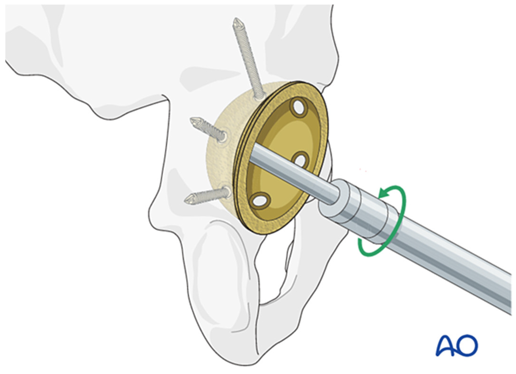
Many procedures can be performed with a “press-fit” application, typically in younger, more active patients with sufficient bone quality. The interface between the bony pelvis and the porous surface of the acetabular cup implant allows for bone ingrowth over time, enhancing fixation stability and promoting the long-term integration of the implant (Figure 1). However, while a certain amount of friction is necessary to promote bony ingrowth at the interface between the pelvis and the acetabular cup, too much movement can prevent this process and cause loosening over time [6,7]. In cases of suboptimal bone quality, cup size issues, or other patient factors, the implant requires further fixation into the bony pelvis using various screw configurations, as demonstrated in Figure 2 [8].
Screw fixation presents challenges, particularly in avoiding critical anatomical structures, such as arteries, veins, and nerves [9,10,11,12]. For hip implants that do not meet the requirements for a press-fit application, determining the proper amount and location of the screws falls upon the operating surgeon’s discretion and preference. Many studies addressing this problem have compared surgical approaches, reviewed common causes of implant failure, and highlighted postoperative patient outcomes [13,14,15,16,17,18,19,20,21].
Computational modeling has become an increasingly valuable tool in assessing THA success. While motion analysis can quantify functional improvements, it does not provide insights into biomechanical optimization. Finite element analysis (FEA), in contrast, allows for precise simulations of stress distribution and implant stability, enabling surgeons to refine implant positioning and fixation strategies [22]. There are little to no studies focusing on predictive modeling methods to optimize the initial surgery and to prevent the need for revision surgery. Biomechanical stress testing, traditionally performed with cadavers or synthetic femurs, has been effectively replicated with computational in silico models [23]. Ultrasound imaging and computed tomography scanning can be useful in some cases, but, while accessible, these methods are limited in how much they can be manipulated to simulate different scenarios [24].
FEA is a versatile yet underutilized tool in surgical planning. It creates a virtual representation of the test object as smaller, interconnected elements. Material properties and boundary conditions are assigned to each element to simulate real-world behaviors. In surgical planning, FEA allows researchers and surgeons to analyze the biomechanical integrity of the hip joint under various conditions, providing insights into stress distribution, load-bearing capacities, and potential areas of concern.
For screw placement, FEA enables a comprehensive examination of the effect of variables, such as screw size, number, length, and orientation, on implant stability and longevity. This approach optimizes screw placement strategies to minimize stress concentrations, assess micromotion, and reduce the risk of complications, like periprosthetic fractures. As a result, the likelihood of revision surgery and associated complications decreases. Moreover, FEA can tailor screw placement to patient-specific factors, such as bone density and morphology, leading to a customized approach to THA. Integrating FEA into preoperative planning enhances the understanding of biomechanical complexities and improves surgical techniques, increasing the success and durability of THA procedures.
Finite element analysis (FEA) has long been valuable for biomechanical modeling, particularly in total hip arthroplasty (THA). By creating a meshed representation of the implant–bone interface, FEA enables the precise simulation of stress–strain distributions under various loading conditions. However, despite its advantages, traditional FEA faces challenges, including high computational costs, as simulations require significant processing power and time. Additionally, FEA-based design optimization is cumbersome, involving manual parameter adjustments and iterative simulations without guaranteeing a globally optimized solution.
To address these challenges, deep learning (DL)-assisted FEA (DL-FEA) has emerged as a promising alternative. DL-FEA leverages pre-trained neural networks to predict stress–strain distributions, significantly reducing computation time while maintaining accuracy. This study explores the integration of DL with FEA to optimize screw fixation strategies, enhancing automation, efficiency, and predictive capabilities.
Deep learning (DL), a subset of machine learning, trains neural networks with large datasets to recognize patterns and make predictions. Although machine learning has only recently been introduced in healthcare, it is already improving surgical training, preoperative planning, and risk assessment. In clinical orthopedics, it is primarily applied for diagnostics, such as classifying injury patterns or detecting occult issues [25].
This study aims to achieve the following: (1) identify the optimal screw configuration for securing the acetabular cup using FEA and (2) evaluate whether a DL algorithm can accurately predict these stress–strain patterns in screw-fixed THA implants. We hypothesize that an optimized screw placement will enhance load distribution, improve implant stability, and promote bone ingrowth, while the trained DL model will serve as a faster, surrogate tool for stress–strain analysis. An optimized screw placement is expected to distribute loads more effectively and optimize the amount of stress and strain needed for bony ingrowth over time between the bony pelvis and acetabular cup. The DL model, after sufficient training using an FEA-generated dataset, is hypothesized to adequately predict stress–strain patterns in a screw-fixed THA. The surrogate model can then be used instead of a more time-consuming and process-intense modeling method like FEA.

2. Design and Methods

2.1. Finite Element Analysis Set Up

In this study, a 3D CAD model of the hip implant was created in SolidWorks (version 2024 SP1.0, SOLIDWORKS® Education Edition, accessed on 6 May 2024) and imported into Ansys (version 2024 R1 (24.1), Ansys Student, accessed on 7 February 2024) for FEA. Material properties were assigned based on real-world parameters, utilizing the Ansys material library where available. The materials used included titanium for the acetabular cup and screws, polyethylene for the liner, and zirconium for the femoral head. Since zirconium was not available in the default Ansys material library, its properties—including Young’s modulus, Poisson’s ratio, and density—were extracted from published literature and manually input into the system to ensure accurate representation.
A mesh was applied to the FEA hip implant model, as shown in Figure 3. The mesh is typically composed of various sizes of triangular elements, upon which simple stress and strain calculations are performed based on the amount of force being applied to each area. By dividing the implant into smaller elements, this enables more precise calculations of mechanical behavior under applied forces.
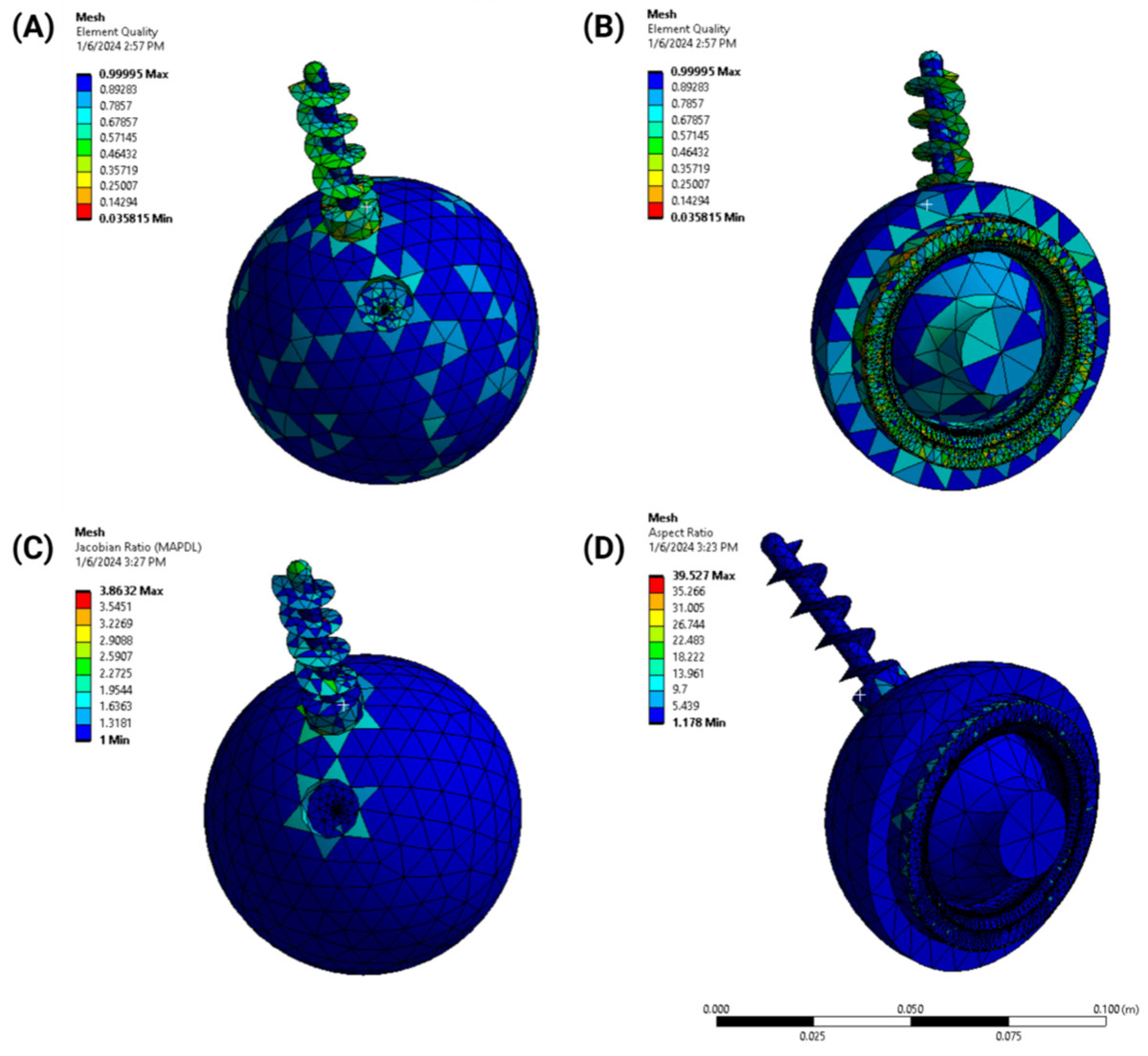
A mesh convergence study was performed to ensure solution accuracy and numerical stability. The study involved systematically refining the mesh while tracking key biomechanical parameters, such as stress distribution, strain, and displacement, until further refinement yielded negligible changes in these outputs. To assess mesh quality, several criteria were considered (Figure 4):
  • Element quality: the aspect ratio and skewness of elements were analyzed to maintain numerical stability;
  • Jacobian ratio: this was used to evaluate the geometric distortion of elements;
  • Aspect ratio: the mesh was optimized to balance computational efficiency and accuracy, ensuring a high-quality representation of the implant geometry.
The size and shape of the mesh were determined based on previous THA studies and validated through sensitivity analysis. A predominantly triangular mesh was selected, with an average element size ranging from 1 mm to 5 mm, ensuring accurate stress distribution modeling while maintaining computational efficiency. The sensitivity analysis confirmed that further mesh refinement resulted in negligible changes in biomechanical outputs, verifying the robustness of the chosen meshing strategy. The selection of mesh parameters also considered previous studies on THA implants to maintain consistency and comparability with validated methodologies.
The final mesh was determined based on an optimal trade-off between computational efficiency and result accuracy. This approach was consistent with prior FEA-based THA studies and verified by comparing results with those reported in the literature.
Figure 4. Mesh quality assessment for simulation fit. (A,B) Element quality, (C) Jacobian ratios, and (D) aspect ratios were produced to ensure that simulation accurately represents fit of the model.
Applsci 15 03722 g004
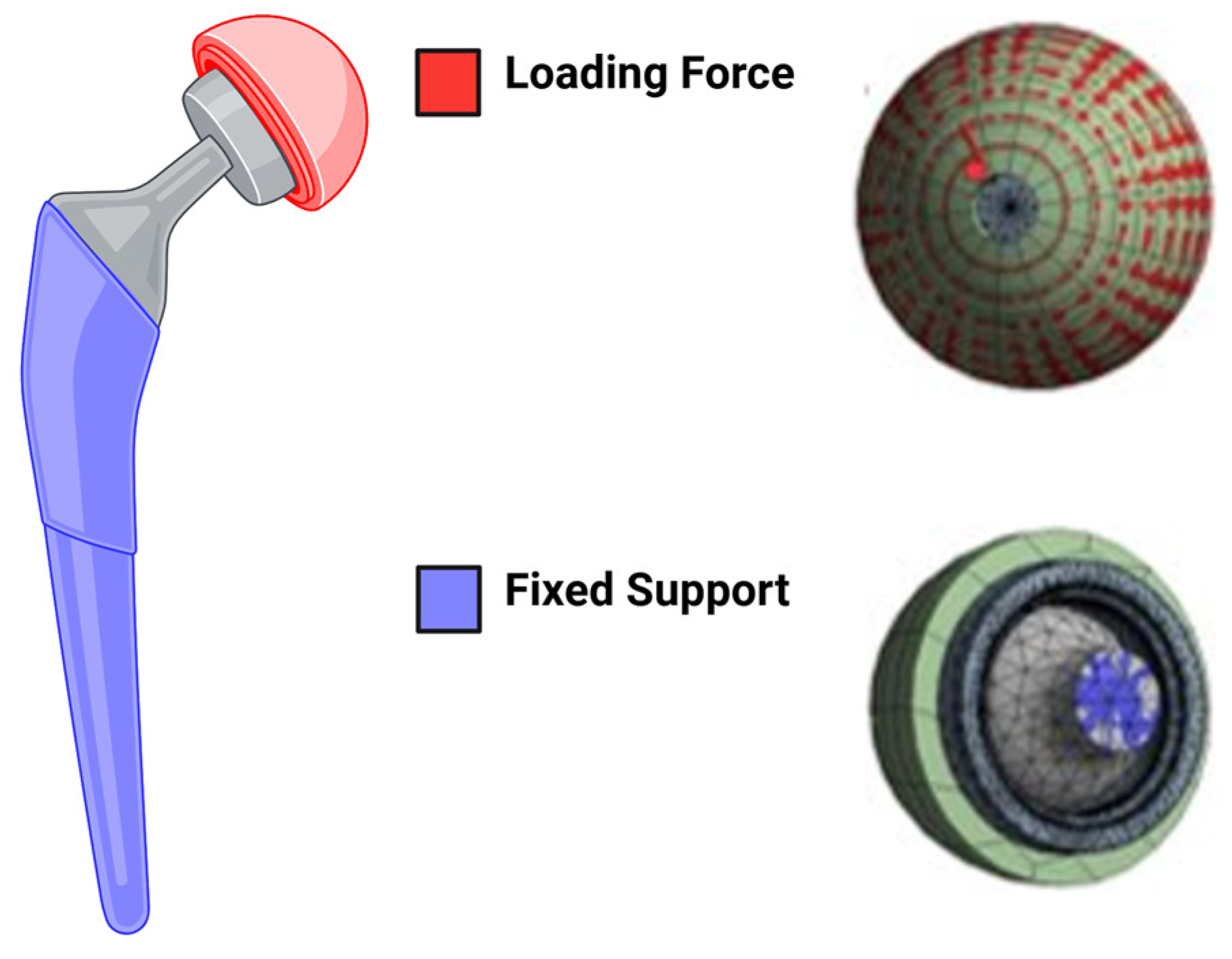
Boundary conditions were applied according to the ASTM F2996-10 Standard Practice and established biomechanical loading scenarios [26,27]. For static structural analysis, based on conditions described in K N Chethan et al. 2019, a load of 2300.5 N was applied to the superior surface of the acetabular cup to maximize joint loading [28]. The femoral stem was completely constrained at the distal end to prevent any translation and rotation, ensuring a clinically relevant fixed support (Figure 5). The simulation was then executed, and the equivalent stress, strain, and total deformation were calculated. These refinements ensure that the FEA model accurately captures the biomechanical behavior of the implant and screw fixation strategies, strengthening the study’s reliability and applicability.
A total of six loading scenarios were then analyzed using 1- and 2-screw configurations. An example of the baseline static structural analysis is shown in Figure 6. To simulate an average male standing, a force of 771.17 N was applied to the construct. To simulate an average female standing, a force of 760.44 N was applied to the construct.
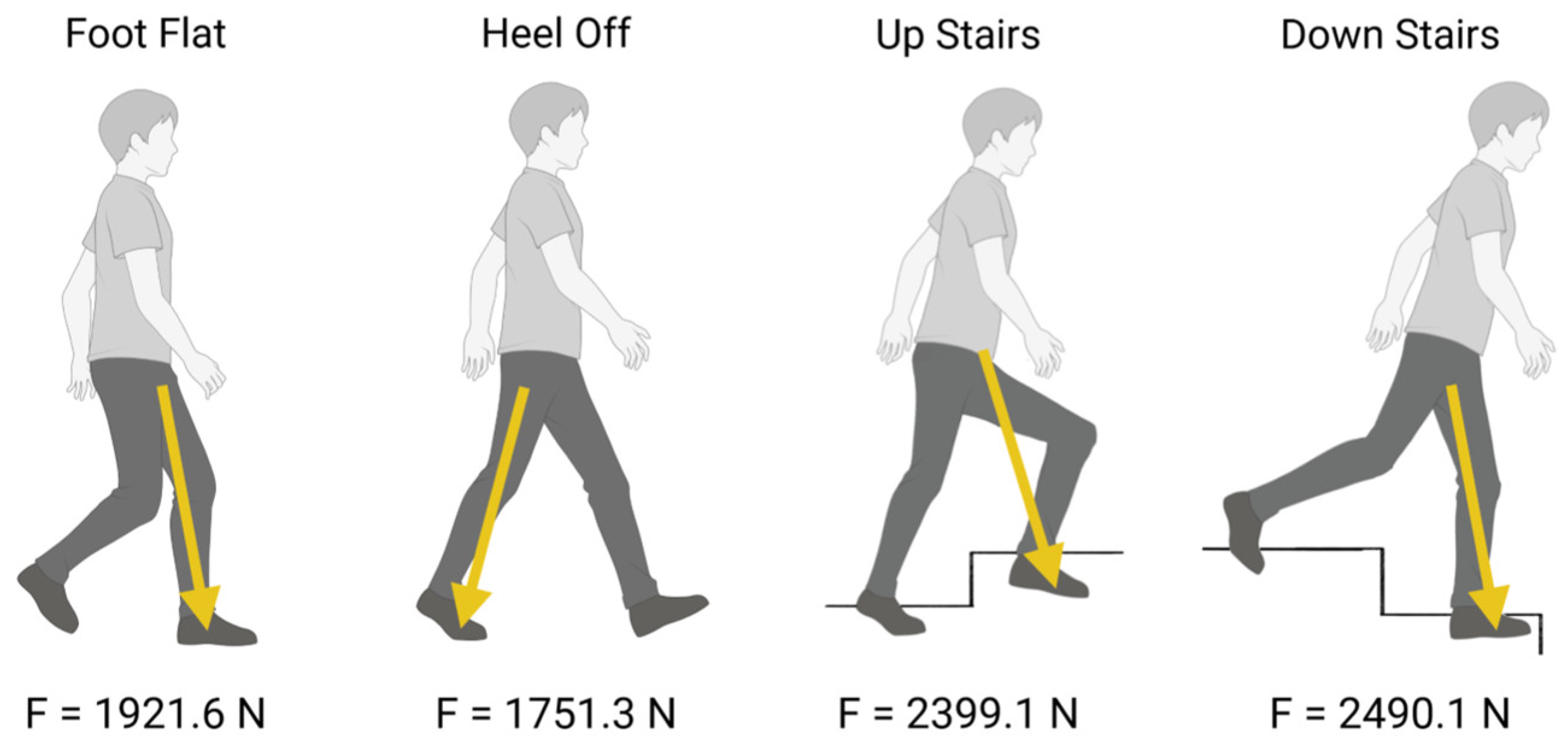
Based on conditions described in Zhu et al. in 2023, the model was subjected to four static loading events for gait analysis (Figure 7) [27]. The first scenario illustrates the loading (foot flat) response of the gait cycle, in which a total force of 1921.6 N was applied to the stance leg as the foot makes contact with the ground at a specific moment in time. The second scenario demonstrates the terminal stance (heel off) phase of the gait cycle, with a force of 1751.3 N applied to the model to simulate the moment at which the weight shifts forward from the stance foot to the forefoot. The third and fourth scenarios simulate going up and down stairs, applying 2399.1 N and 2490.1 N to the implant, respectively.

2.2. Design Optimization

Following the initial FEA, simulation parameters were refined through an optimization process. The Ansys Design Exploration Response Surface feature was used for this step. This feature involved analytical and visualization techniques to assess the impact of input variables on model performance. The Response Surface simulation was utilized to systematically generate key optimization metrics, ensuring a data-driven refinement of the design.
The Goodness of Fit metric was used to validate the accuracy of the simulation by comparing predicted values with experimental data. This ensured model reliability before further optimization, particularly in predicting stress–strain distributions for improved screw fixation strategies. This statistical measure ensured that the predictions were reliable before further optimization, particularly in assessing stress–strain distributions critical for THA screw fixation.
The Response Graphs provided insight into how output variables (such as stress, strain, and deformation) varied in response to changes in design parameters. These graphs helped visualize non-linear trends, guiding parameter selection for improved implant performance.
To further refine the design, a Local Sensitivity Analysis was conducted to quantify the impact of small variations in parameters such as screw length, cup positioning, and material stiffness. The results were visualized using Local Sensitivity Curves, which illustrated how specific parameters influenced implant stability, identifying the most critical factors for performance enhancement.
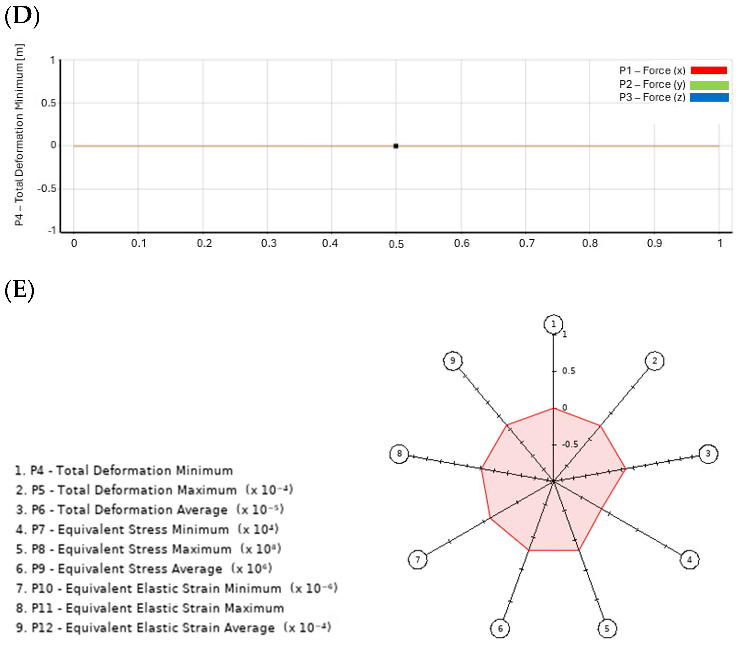
Lastly, Spider Charts (Radar Charts) were employed to analyze the combined effect of multiple design variables. By mapping interactions between factors, such as bone quality, implant orientation, and fixation techniques, these charts provided a comprehensive assessment of trade-offs, aiding in the selection of an optimal screw configuration.

2.3. Deep Learning Surrogate Model

The data generated in Ansys, namely the resultant equivalent stress, were exported to a comma-separated value (CSV) file. These data were then imported into MATLAB (Version 24.2.0.2806996 (R2024b), MathWorks, accessed on 5 April 2024) as a table, where a DL network was trained to predict the equivalent stress distributions over the geometry based on the X-, Y-, and Z-coordinates of the mesh. A linear regression algorithm was used to develop the neural network to ensure continuity over the entire geometry. The model architecture included the following:
  • Input: X-, Y-, Z-coordinates of the mesh;
  • Hidden layers: fully connected layers with ReLU activation;
  • Output: predicted stress values;
  • Training: 80% of the data were used for training, 10% for validation, and 10% for testing.
The network was iterated for 200 epochs, with a sampling size of 10,000 entries for the table.
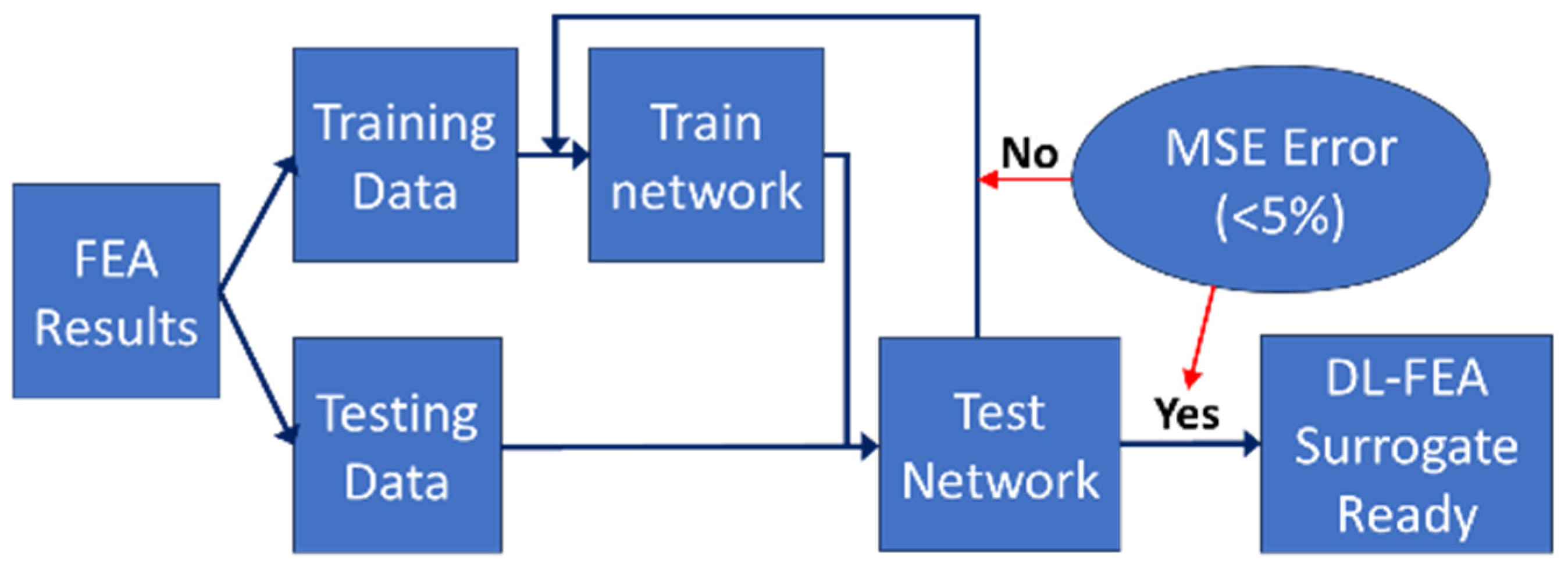
Once the network was trained, the test data were used to evaluate the mean squared error (MSE) of the network’s predictions. If the MSE calculated from the data was less than 5%, the model was considered sufficient for use in other cases. However, if the MSE was greater than 5%, the network was retrained. Once the network achieved an MSE below 5%, it was deemed ready for use as a DL-FEA surrogate to calculate the equivalent stress distributions over the entire geometry. The diagram in Figure 8 summarizes this process.

2.4. Comparative Analysis

To evaluate the DL-FEA model’s effectiveness, a structured comparative analysis was conducted using multiple assessment methodologies. The methods employed include the following:
  • Accuracy assessment: The DL-FEA model’s predictions were compared against traditional FEA results to evaluate stress–strain distributions. Mean squared error (MSE) and correlation coefficients were computed to quantify deviations in predicted deformation patterns.
  • Computational efficiency evaluation: The processing times required for both traditional FEA and DL-FEA were recorded and compared. This involved measuring the computation time for multiple loading scenarios and assessing efficiency gains from using the DL-based surrogate model.
  • Empirical validation: The DL-FEA model’s stress distribution outputs were cross-referenced with published experimental data on acetabular cup fixation. This comparison ensured that simulation outputs aligned with real-world implant behavior and failure mechanisms.
  • Robustness and sensitivity analysis: The model’s response to variations in input parameters, such as material properties and boundary conditions, was analyzed. Sensitivity testing was performed to determine the stability of predictions under different simulation settings.

3. Results

3.1. Finite Element Analysis

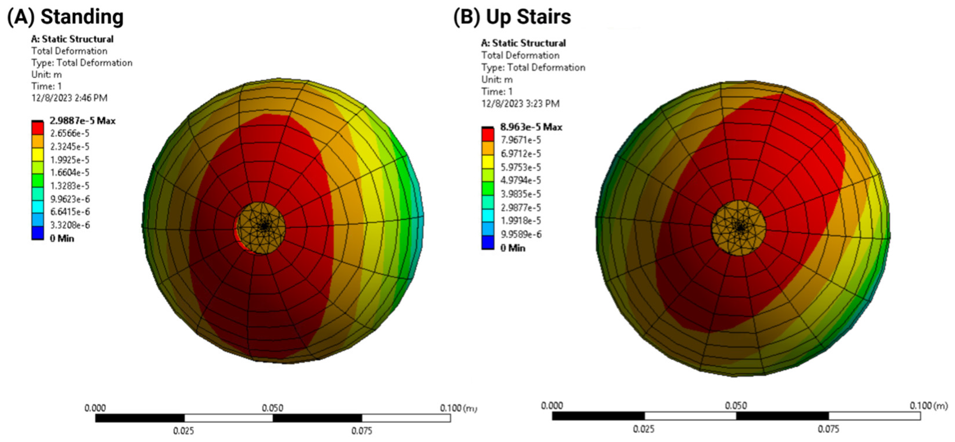
To assess the influence of applied force, deformation distribution maps were generated for the male model in the standing case and ascending stairs case, comparing results when the minimum and maximum force was applied to the implant (Figure 9). As anticipated, the resulting deformation was not uniform across the surface of the implant. Due to differences in the X-, Y-, and Z-components of the applied force, the area of greatest deformation shifted in location.
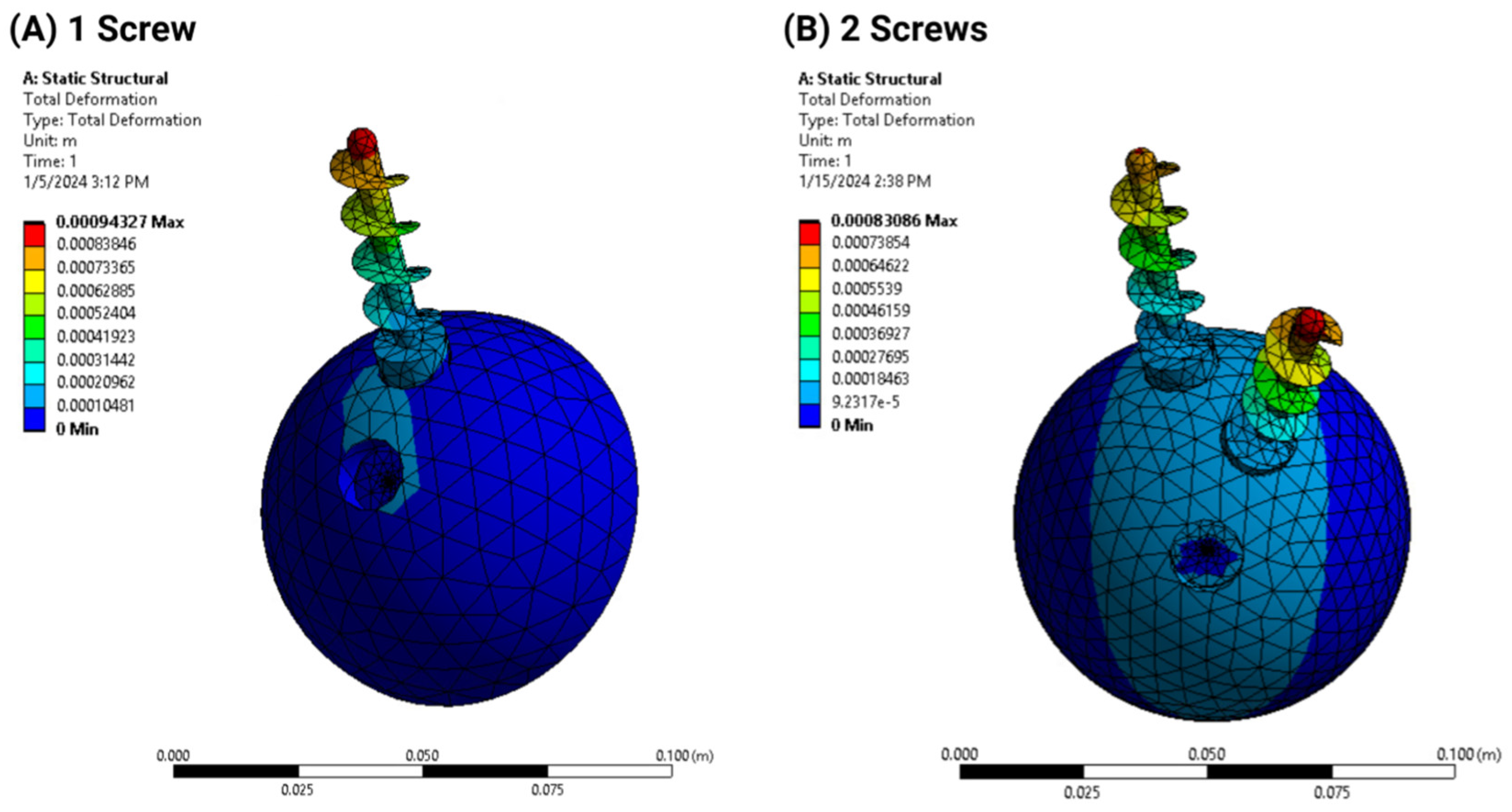
Further testing revealed that the shear deformation observed in the ascending stairs loading case could potentially affect the contact between the acetabular cup and the liner. In the no-screw configuration, the deformation was concentrated on the outer surface of the acetabular cup. In contrast, the addition of at least one screw helped reduce the effects of applied loads and maintained the structural integrity of the acetabular cup, as demonstrated in Figure 10. Interestingly, the 2-screw model experienced more deformation than the 1-screw model, as indicated by the larger light blue highlighted areas in the figures.
In summary, FEA findings indicate the following:
  • Deformation distribution varied with screw configuration, with the 2-screw model exhibiting greater stability than the 1-screw model;
  • Load simulations confirmed that additional screws reduced acetabular cup displacement but increased stress concentration in adjacent bone structures.

3.2. Design Optimization Outcomes

The design optimization process was conducted to refine key implant parameters before training the deep learning surrogate model. The Goodness of Fit, Response, Local Sensitivity, and Spider Graphs generated by the Response Surface simulation allowed for the identification of the most influential variables affecting stress distribution and fixation stability. This optimization ensured that the dataset used for deep learning training was composed of well-validated simulations, enhancing the model’s ability to predict stress–strain responses with greater precision and accuracy. These simulation processes are summarized in Figure 11:
  • Goodness of Fit: This figure illustrates the model’s predictive accuracy by comparing simulated values against experimental (reference) results. A high Goodness of Fit score indicates strong correlation and model reliability, ensuring that stress–strain distributions are accurately represented. Notably, the results indicate that higher accuracy is achieved when screw positioning is optimized, confirming the importance of precise placement.
  • 3D Response Graph: This graph visualizes how different input parameters, such as screw position and material properties, influence key output variables, like stress and strain. Non-linear trends are highlighted, allowing for the identification of optimal configurations that minimize stress concentrations and maximize implant stability. The results show that improper screw angulation leads to uneven stress distribution, which can compromise implant integrity.
  • Local Sensitivity Graph: This figure quantifies how small variations in design parameters affect the overall implant performance. By analyzing sensitivity across multiple variables, the graph helps determine which parameters have the most significant impact on stress distribution and fixation stability. The results emphasize that even minor deviations in bone density significantly impact screw fixation strength, reinforcing the need for patient-specific planning.
  • Local Sensitivity Curves: These curves offer a detailed visualization of the sensitivity analysis results, illustrating how minor changes in specific input parameters influence the biomechanical behavior of the implant. This aids in refining implant design to enhance performance and reduce failure risks. The findings suggest that higher-grade titanium screws reduce peak stress concentrations, enhancing long-term stability.
  • Spider Chart (Radar Chart): The Radar Chart provides a comprehensive assessment of trade-offs between multiple design variables, such as implant orientation, bone quality, and screw fixation techniques. By mapping these interactions, the figure aids in selecting the most balanced and effective screw configuration for optimal implant performance. The results confirm that increasing screw length improves load distribution but may also elevate stress in adjacent bone structures, requiring a careful balance in design choices.
These figures collectively contribute to the iterative optimization process, ensuring that the final implant design is robust, efficient, and tailored for enhanced surgical outcomes.
Figure 11. Simulations generated for design optimization. (A) Goodness of Fit, (B) 3D Response Graph, (C) Local Sensitivity Graph, (D) Local Sensitivity Curves, and (E) Spider Chart.
Applsci 15 03722 g011aApplsci 15 03722 g011b

3.3. Deep Learning Model Analysis

Using the dataset produced by ANSYS after FEA and optimization, a DL network with 10 layers, ReLU activation, and MSE used as a metric to assess the accuracy of the network was trained to predict those stress and strain distributions across the acetabular cup implant. The dataset, which consisted of stress, strain, and deformation values for various screw configurations and loading conditions, was imported into MATLAB for neural network training. Initially, a linear regression model was applied to the dataset, which produced low accuracy (MSE = 91.56%) when compared to the original FEA data (Figure 12).
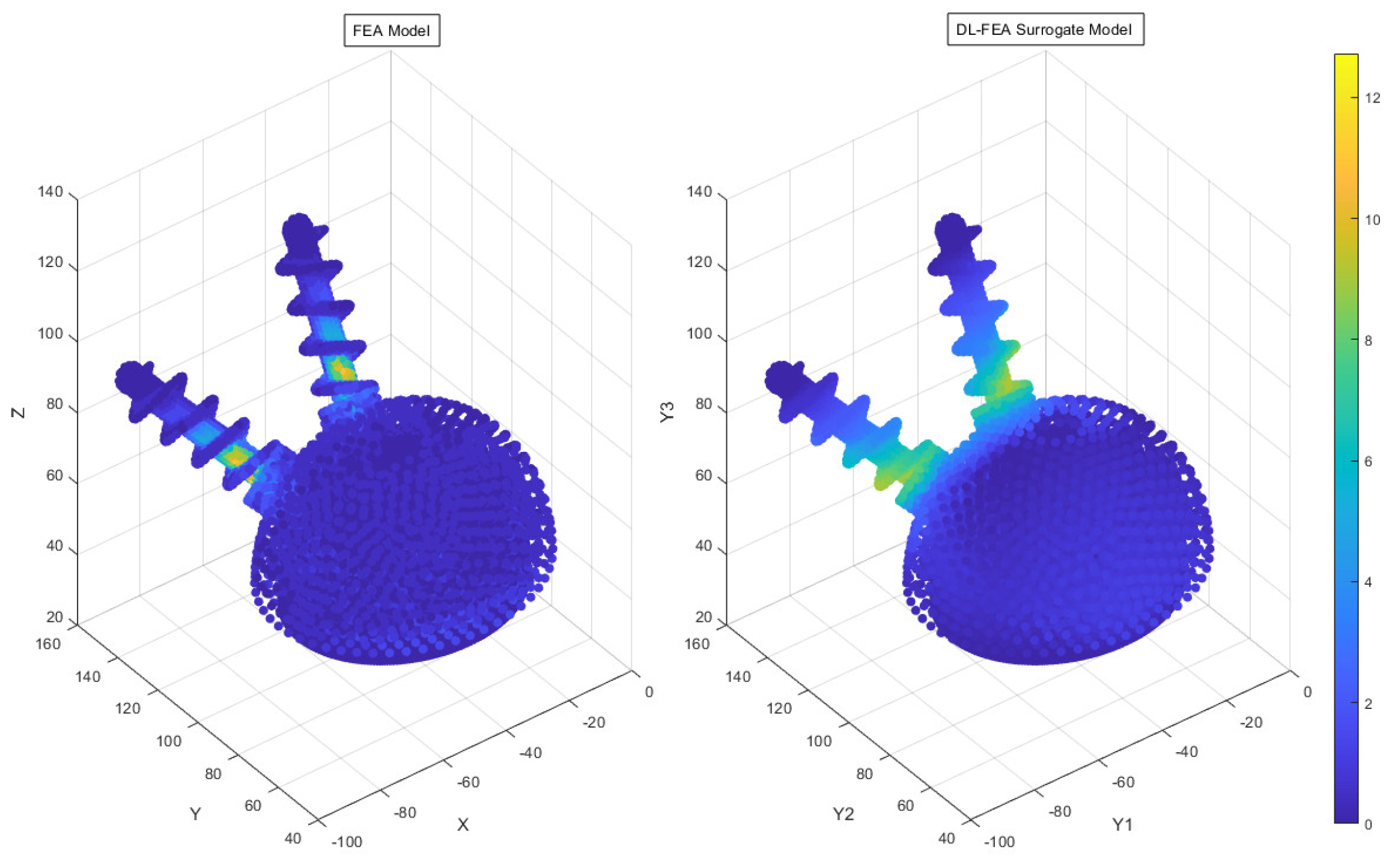
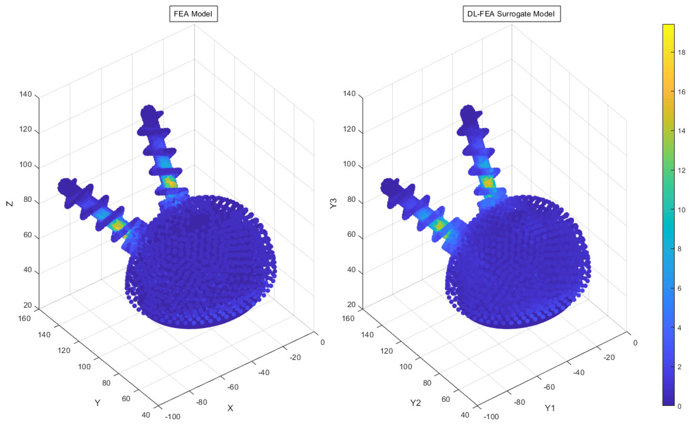
Subsequently, a non-linear regression algorithm was implemented to improve the model’s performance. This adjustment resulted in a significant reduction in error (MSE = 24.06%), indicating improved prediction accuracy. The non-linear regression model demonstrated a more accurate representation of stress and strain patterns, especially in areas of high deformation (Figure 13). Qualitative analysis of the DL model output revealed a closer match to the FEA results, particularly in the stress concentration regions and deformation trends across different screw configurations.

3.4. Comparative Analysis Results

The comparative analysis focused on four key aspects: accuracy, computational efficiency, empirical validation, and robustness.
  • Accuracy findings: The DL-FEA model demonstrated reasonable accuracy in replicating traditional FEA results, with an MSE of 24.06%. Minor deviations in high-stress regions indicate areas for future refinement.
  • Computational efficiency gains: traditional FEA required extensive computation time for complex loading cases, whereas DL-FEA provided near-instantaneous predictions, highlighting its potential for real-time surgical planning.
  • Empirical validation outcomes: the stress distribution patterns from DL-FEA closely aligned with empirical studies on acetabular cup fixation, supporting its reliability.
  • Robustness and sensitivity insights: sensitivity analyses confirmed that DL-FEA maintained stability across varying input conditions, successfully adapting to changes in bone density and implant orientation, demonstrating its applicability for personalized implant optimization.
To evaluate the effectiveness of DL-FEA compared to traditional FEA, multiple assessment methodologies were employed. The key findings demonstrate that DL-FEA offers substantial improvements over traditional FEA in several aspects:
  • Computational cost reduction: Traditional FEA requires extensive computation for complex loading scenarios, making real-time surgical planning impractical. In contrast, once trained, the DL-FEA model generates near-instantaneous predictions, eliminating the need for repeated full-scale simulations and significantly reducing processing time.
  • Streamlined optimization process: Traditional FEA relies on manual parameter tuning and iterative analysis, making design optimization labor-intensive. DL-FEA automates this process using machine learning algorithms to predict optimal stress distributions, making data-driven optimization faster, and more efficient.
  • Comparable predictive accuracy: While traditional FEA remains the gold standard for biomechanical modeling, the DL-FEA model demonstrated a reasonable MSE of 24.06%, effectively replicating deformation and stress–strain patterns. Future improvements, including expanding the dataset and refining neural network architectures, could enhance the accuracy further.
The results demonstrate that while traditional FEA remains essential for biomechanical modeling, DL-FEA presents a viable alternative with significant computational advantages. Future refinements will focus on improving the deep learning model, increasing dataset diversity, and incorporating additional boundary conditions to enhance accuracy and clinical applicability.
Additionally, the results indicate that the number, length, and angulation of screws significantly influence acetabular cup stability. Increasing the number of screws generally reduces micromotion, but excessive screws can lead to higher stress concentrations in adjacent bone structures. Optimal screw length is crucial for anchoring in denser bone regions while avoiding stress shielding, but we only considered the standard screw length for this study. Screw angulation directly affects load distribution, with improper angles increasing the stress around screw heads. A well-balanced configuration minimizes implant displacement while maintaining favorable stress distribution.

4. Discussion

FEA simulations demonstrated that acetabular cup deformation is significantly influenced by loading conditions and screw configuration. The highest deformation occurred in the no-screw configuration, indicating reduced implant stability. The addition of screws generally improved fixation, with the 2-screw configuration providing greater stability at the cost of slightly higher stress concentrations in adjacent bone structures. These findings suggest that screw fixation plays a crucial role in optimizing load distribution and reducing the risk of implant loosening. However, the trade-off between additional fixation and potential bone stress must be carefully considered to avoid complications, such as stress shielding or periprosthetic fractures.
Quantitative analysis showed that the 2-screw configuration reduced implant micromotion by approximately 18% compared to the no-screw model, while also lowering peak von Mises stress by 12%. However, stress concentrations near the screw heads increased by nearly 22%, highlighting a potential risk for bone weakening in those regions. Similarly, increasing the screw length improved the anchoring strength but led to stress shielding effects in adjacent cortical bone, suggesting an optimal balance is necessary to minimize bone resorption over time. These findings reinforce the need for the computational optimization of screw placement to ensure biomechanical stability without introducing excessive localized stresses.
The integration of DL with FEA enabled the predictive modeling of stress–strain distributions, reducing computational time compared to traditional FEA simulations. While the DL-FEA model successfully captured deformation patterns, its mean squared error (MSE) of 24.06% highlights areas for refinement. The primary sources of discrepancy include dataset limitations and the need for more sophisticated non-linear regression techniques to enhance accuracy. Despite these limitations, the DL-FEA framework presents a promising approach for streamlining implant design and preoperative planning. Further improvements in data preprocessing and feature engineering could help refine the predictive capabilities of the model.
From a clinical perspective, this study underscores the importance of patient-specific screw placement. While increasing the number of screws generally enhances stability, excessive fixation can lead to localized stress concentrations, potentially weakening the surrounding bone. Proper screw angulation and placement in high-density bone regions are critical factors in ensuring optimal fixation. The findings support the development of personalized screw placement strategies that account for individual bone quality and anatomical variations, ultimately improving long-term implant success rates. This reinforces the need for advanced imaging techniques and computational models to guide intraoperative decision-making and optimize patient-specific surgical strategies.
Future refinements to the DL model should focus on expanding the dataset to incorporate a wider range of bone densities, screw configurations, and loading conditions. Additionally, integrating clinical imaging data from CT or MRI scans will enhance the model’s applicability for patient-specific surgical planning. Further validation through experimental cadaveric testing and retrospective clinical data analysis will be critical to confirming the real-world accuracy of the DL-FEA predictions. These validation steps will provide direct empirical comparisons between model-predicted stress–strain distributions and actual biomechanical outcomes, helping bridge the gap between computational modeling and clinical practice.
By leveraging computational modeling and machine learning, this study provides a foundation for optimizing acetabular cup fixation in THA. The proposed approach holds potential for improving surgical outcomes by enabling data-driven, patient-specific decision-making in orthopedic implant design and placement. With continued refinement, DL-FEA could evolve into an essential tool for optimizing THA fixation strategies, ultimately leading to better patient outcomes and lower revision rates.

5. Conclusions

This study presents a computational approach that integrates finite element analysis (FEA) and deep learning (DL) to optimize screw fixation strategies in total hip arthroplasty (THA). The results demonstrate that optimized screw placement enhances load distribution, minimizes stress concentrations, and improves implant stability. By leveraging DL-FEA, this approach significantly reduces the computational time compared to traditional FEA while maintaining predictive accuracy.
Key findings indicate that increasing the number of screws generally improves fixation stability but may also introduce localized stress concentrations in adjacent bone structures. This study underscores the importance of optimizing screw placement, length, and angulation to achieve a balance between implant stability and stress minimization. Furthermore, the results suggest that DL-FEA can serve as a viable alternative to traditional FEA in preoperative planning, offering a more efficient predictive tool for assessing fixation strategies.
Despite the promising results, some limitations remain. The current model primarily considers static and limited motion conditions, requiring further validation under dynamic loading scenarios, such as gait cycles and impact forces. Additionally, empirical validation through cadaveric studies and clinical imaging is essential to improve the generalizability and applicability of DL-FEA in surgical practice.
Future research will focus on expanding the dataset to include a broader range of anatomical and biomechanical conditions, incorporating patient-specific modeling from CT/MRI data, and refining deep learning architectures to enhance prediction accuracy. Additionally, comparative analysis with other machine learning methods will be conducted to assess model performance relative to alternative computational approaches.
By addressing these challenges, DL-FEA can evolve into an indispensable tool for optimizing surgical planning, improving patient-specific implant fixation strategies, and ultimately reducing revision rates in THA. This research provides a pathway toward more precise, data-driven decision-making in orthopedic surgery, contributing to the advancement of personalized medicine in joint replacement procedures.

Author Contributions

Conceptualization, J.S., E.T.Y., K.W. and C.-H.G.; data curation, J.S.; formal analysis, J.S. and E.T.Y.; investigation, J.S. and E.T.Y.; methodology, J.S., E.T.Y., J.A. and C.-H.G.; project administration, C.-H.G.; resources, C.-H.G.; software, E.T.Y. and J.A.; supervision, C.-H.G.; validation, K.W. and C.-H.G.; writing—original draft preparation, E.T.Y.; writing—review and editing, E.T.Y., C.-H.G. and K.W. All authors have read and agreed to the published version of the manuscript.

Funding

This research received no external funding.

Institutional Review Board Statement

Not applicable.

Informed Consent Statement

Not applicable.

Data Availability Statement

The data presented in this study are available on request from the corresponding author. The data are not publicly available due to privacy.

Acknowledgments

The authors acknowledge the support of the University of Texas at Tyler, California Health Sciences University College of Osteopathic Medicine, University of California, Davis, and the Runatek Corporation, Dallas.

Conflicts of Interest

The authors declare no conflicts of interest.

References

  1. Cieremans, D.; Shah, A.; Slover, J.; Schwarzkopf, R.; Meftah, M. Trends in Complications and Outcomes in Patients Aged 65 Years and Younger Undergoing Total Hip Arthroplasty: Data from the American Joint Replacement Registry. J. Am. Acad. Orthop. Surg. Glob. Res. Rev. 2023, 7, e22. [Google Scholar] [CrossRef] [PubMed]
  2. Kelmer, G.; Stone, A.H.; Turcotte, J.; King, P.J. Reasons for Revision: Primary Total Hip Arthroplasty Mechanisms of Failure. J. Am. Acad. Orthop. Surg. 2021, 29, 78–87. [Google Scholar] [CrossRef] [PubMed]
  3. Angerame, M.R.; Fehring, T.K.; Masonis, J.L.; Mason, J.B.; Odum, S.M.; Springer, B.D. Early Failure of Primary Total Hip Arthroplasty: Is Surgical Approach a Risk Factor? J. Arthroplast. 2018, 33, 1780–1785. [Google Scholar] [CrossRef] [PubMed]
  4. Konow, T.; Baetz, J.; Melsheimer, O.; Grimberg, A.; Morlock, M. Factors Influencing Periprosthetic Femoral Fracture Risk. Bone Jt. 2021, 103, 650–658. [Google Scholar] [CrossRef]
  5. Zywiel, M.G.; Mustafa, L.H.; Bonutti, P.M.; Mont, M.A. Are Abductor Muscle Quality and Previous Revision Surgery Predictors of Constrained Liner Failure in Hip Arthroplasty? Int. Orthop. 2011, 35, 797–802. [Google Scholar] [CrossRef]
  6. Qin, Y.X.; McLeod, K.J.; Guilak, F.; Chiang, F.P.; Rubin, C.T. Correlation of Bony Ingrowth to the Distribution of Stress and Strain Parameters Surrounding a Porous-Coated Implant. J. Orthop. Res. 1996, 14, 862–870. [Google Scholar] [CrossRef]
  7. Nam, H.-J.; Lim, Y.-W.; Jo, W.-L.; Bahk, J.H.; Kwon, S.Y.; Park, H.C.; AlShammari, S.M. Is the Construct Stability of the Acetabular Cup Affected by the Acetabular Screw Configuration in Bone Defect Models? J. Orthop. Surg. Res. 2023, 18, 354. [Google Scholar] [CrossRef]
  8. AO Foundation; Total Hip Arthroplasty for Basicervical Femoral Neck Fractures. AO Surgery Reference: Davos, Switzerland, 2022. Available online: https://surgeryreference.aofoundation.org (accessed on 16 January 2025).
  9. Wasielewski, R.C.; Cooperstein, L.A.; Kruger, M.P.; Rubash, H.E. Acetabular Anatomy and the Transacetabular Fixation of Screws in Total Hip Arthroplasty. J. Bone Jt. Surg. Am. 1990, 72, 501–508. [Google Scholar] [CrossRef]
  10. Wasielewski, R.C.; Galat, D.D.; Sheridan, K.C.; Rubash, H.E. Acetabular Anatomy and Transacetabular Screw Fixation at the High Hip Center. Clin. Orthop. Relat. Res. 2005, 438, 171–176. [Google Scholar] [CrossRef]
  11. Ohashi, H.; Kikuchi, S.; Aota, S.; Hakozaki, M.; Konno, S. Surgical Anatomy of the Pelvic Vasculature, With Particular Reference to Acetabular Screw Fixation in Cementless Total Hip Arthroplasty in the Asian Population. J. Orthop. Surg. 2017, 25. [Google Scholar] [CrossRef]
  12. Meldrum, R.; Johansen, R.L. Safe Screw Placement in Acetabular Revision Surgery. J. Arthroplasty 2001, 16, 953–960. [Google Scholar] [CrossRef] [PubMed]
  13. Aguado-Maestro, I.; de Blas-Sanz, I.; Sanz-Peñas, A.E.; Campesino-Nieto, S.V.; Diez-Rodríguez, J.; Valle-López, S.; Espinel-Riol, A.; Fernández-Díez, D.; García-Alonso, M. Dual Mobility Cups as the Routine Choice in Total Hip Arthroplasty. Medicina 2022, 58, 528. [Google Scholar] [CrossRef] [PubMed]
  14. Davis, E.T.; Pagkalos, J.; Kopjar, B. Using an Asymmetric Crosslinked Polyethylene Liner in Primary Total Hip Arthroplasty Is Associated With a Lower Risk of Revision Surgery: An Analysis of the National Joint Registry. Bone Jt. J. 2021, 103, 1479–1487. [Google Scholar] [CrossRef]
  15. Fernandez, M.A.; Achten, J.; Parsons, N.; Griffin, X.L.; Png, M.-E.; Gould, J.; McGibbon, A.; Costa, M.L. Cemented or Uncemented Hemiarthroplasty for Intracapsular Hip Fracture. N. Engl. J. Med. 2022, 386, 521–530. [Google Scholar] [CrossRef]
  16. Lachiewicz, P.F.; Kleeman, L.T.; Seyler, T. Bearing Surfaces for Total Hip Arthroplasty. J. Am. Acad. Orthop. Surg. 2018, 26, 45–57. [Google Scholar] [CrossRef]
  17. Rogmark, C.; Nåtman, J.; Jobory, A.; Hailer, N.P.; Cnudde, P. The Association of Surgical Approach and Bearing Size and Type With Dislocation in Total Hip Arthroplasty for Acute Hip Fracture. Bone Jt. J. 2022, 104, 844–851. [Google Scholar] [CrossRef]
  18. Rogmark, C.; Nauclér, E. Dual Mobility Cups Do Not Reduce the Revision Risk for Patients With Acute Femoral Neck Fracture: A Matched Cohort Study From the Swedish Arthroplasty Register. Injury 2022, 53, 620–625. [Google Scholar] [CrossRef]
  19. Malahias, M.-A.; Ma, Q.-L.; Jang, S.J.; Loucas, M.; Gu, A.; Gkiatas, I.; Sedran, J.-C.; Nikolaou, V.S.; Sculco, P.K. Polyethylene Liner Cementation Into a Well-Fixed Metal Acetabular Shell for the Management of Periacetabular Osteolysis: A Systematic Review. Eur. J. Orthop. Surg. Traumatol. 2022, 32, 1459–1468. [Google Scholar] [CrossRef]
  20. Nebergall, A.K.; Rader, K.; Palm, H.; Malchau, H.; Greene, M.E. Precision of Radiostereometric Analysis (RSA) of Acetabular Cup Stability and Polyethylene Wear Improved by Adding Tantalum Beads to the Liner. Acta Orthop. 2015, 86, 563–568. [Google Scholar] [CrossRef]
  21. Tian, J.-L.; Sun, L.; Hu, R.-Y.; Han, W.; Tian, X.-B. Correlation of Cup Inclination Angle With Liner Wear for Metal-on-Polyethylene in Hip Primary Arthroplasty. Orthop. Surg. 2017, 9, 186–190. [Google Scholar] [CrossRef]
  22. Bahl, J.S.; Nelson, M.J.; Taylor, M.; Solomon, L.B.; Arnold, J.B.; Thewlis, D. Biomechanical Changes and Recovery of Gait Function After Total Hip Arthroplasty for Osteoarthritis: A Systematic Review and Meta-Analysis. Osteoarthr. Cartil. 2018, 26, 847–863. [Google Scholar] [CrossRef]
  23. Wang, K.; Kenanidis, E.; Miodownik, M.; Tsiridis, E.; Moazen, M. Periprosthetic Fracture Fixation of the Femur Following Total Hip Arthroplasty: A Review of Biomechanical Testing-Part II. Clin. Biomech. 2019, 61, 144–162. [Google Scholar] [CrossRef] [PubMed]
  24. Riglet, L.; Viste, A.; De Leissègues, T.; Naaim, A.; Liebgott, H.; Dumas, R.; Fessy, M.H.; Gras, L.L. Accuracy and Precision of the Measurement of Liner Orientation of Dual Mobility Cup Total Hip Arthroplasty Using Ultrasound Imaging. Med. Eng. Phys. 2022, 108, 103877. [Google Scholar] [CrossRef]
  25. Ko, S.; Pareek, A.; Ro, D.H.; Lu, Y.; Camp, C.L.; Martin, R.K.; Krych, A.J. Artificial Intelligence in Orthopedics: Three Strategies for Deep Learning With Orthopedic Specific Imaging. Knee Surg. Sports Traumatol. Arthrosc. 2022, 30, 758–761. [Google Scholar] [CrossRef] [PubMed]
  26. ASTM F2996-20; Standard Practice for Finite Element Analysis (FEA) of Non-Modular Metallic Orthopaedic Hip Femoral Stems. ASTM International: West Conshohocken, PA, USA, 2020.
  27. Zhu, Y.; Babazadeh-Naseri, A.; Dunbar, N.J.; Brake, M.R.W.; Zandiyeh, P.; Li, G.; Leardini, A.; Leardini, B.; Leardini, B.J. Finite Element Analysis of Screw Fixation Durability Under Multiple Boundary and Loading Conditions for a Custom Pelvic Implant. Med. Eng. Phys. 2023, 111, 103930. [Google Scholar] [CrossRef] [PubMed]
  28. Chethan, K.N.; Zuber, M.; Shenoy, S.; Kini, C.R. Static Structural Analysis of Different Stem Designs Used in Total Hip Arthroplasty Using Finite Element Method. Heliyon 2019, 5, e01767. [Google Scholar] [CrossRef]
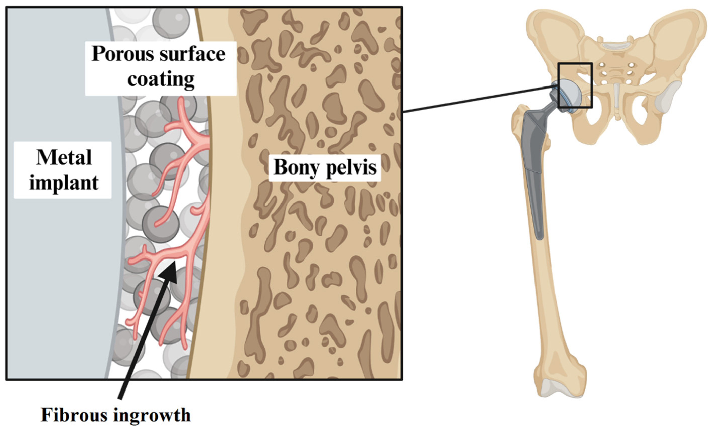
Figure 1. Bone ingrowth in acetabular cup fixation. Illustration demonstrating bone ingrowth between bony pelvis and porous surface of metal acetabular cup implant. Ingrowth enhances fixation stability and long-term integration of implant, reducing risk for failure from loosening.
Applsci 15 03722 g001
Figure 2. Additional screw fixation for acetabular cup. Reproduced with permission from AO Surgery Reference (Copyright by AO Foundation, Switzerland) [8].
Applsci 15 03722 g002
Figure 3. Mesh applied to hip implant model for FEA. Meshed representation of FEA hip implant model, composed of triangular elements, allows for precise stress and strain calculations by distributing applied forces across smaller elements, improving accuracy of mechanical behavior simulations.
Applsci 15 03722 g003
Figure 5. Application of boundary conditions. Loading force was applied to superior surface of acetabular cup, and femoral stem was fixed at distal end to prevent translation and rotation.
Applsci 15 03722 g005
Figure 6. FEA deformation distribution with screw fixation in static case. (A) 1-screw configuration and (B) 2-screw configuration.
Applsci 15 03722 g006
Figure 7. Loading scenarios for gait analysis. Model was subjected to four loading scenarios: (1) loading phase (foot flat), (2) terminal stance (heel off), (3) stair ascent, and (4) stair descent.
Applsci 15 03722 g007
Figure 8. Flow chart of DL-FEA surrogate modeling process. Workflow for training DL-FEA surrogate model to predict stress patterns across construct.
Applsci 15 03722 g008
Figure 9. FEA deformation distribution in static and loading cases. Comparison of deformation patterns in (A) standing and (B) stair ascent scenarios, with minimum and maximum applied forces. Area of greatest deformation (highlighted in red) is due to differences in X-, Y-, and Z-components of applied force.
Applsci 15 03722 g009
Figure 10. FEA deformation distribution with screw fixation in loading case: (A) 1-screw and (B) 2-screw model. 2-screw model experienced more deformation than 1-screw model, highlighted in light blue.
Applsci 15 03722 g010
Figure 12. Comparison of FEA and DL-FEA using linear regression. Initial attempt with linear regression model yielded low accuracy (MSE = 91.56%), demonstrating poor fit to original FEA data.
Applsci 15 03722 g012
Figure 13. Comparison of FEA and DL-FEA using non-linear regression. Non-linear regression model yielded better accuracy, with lower mean squared error (MSE = 24.06%). Visualization of deformation distribution matched original FEA data in terms of location and pattern.
Applsci 15 03722 g013
Disclaimer/Publisher’s Note: The statements, opinions and data contained in all publications are solely those of the individual author(s) and contributor(s) and not of MDPI and/or the editor(s). MDPI and/or the editor(s) disclaim responsibility for any injury to people or property resulting from any ideas, methods, instructions or products referred to in the content.