

High-Frequency Passive Acoustic Recognition in Underwater Environments: Echo-Based Coding for Layered Elastic Shells


Abstract
1. Introduction
- (1)
- First theoretical framework linking layered cylindrical shell geometry to acoustic coding mechanisms.
- (2)
- Development of a hybrid NMS-FEM validation framework for systematic design optimization.
- (3)
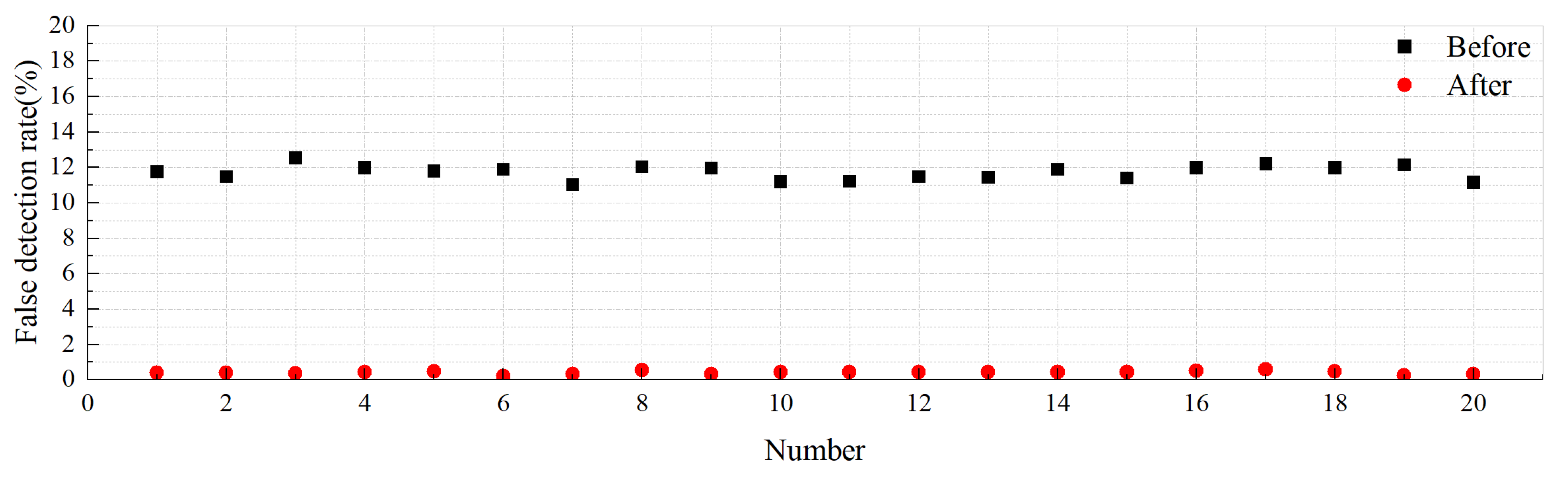
- 99% detection success rate at 3 dB SNR via impedance contrast optimization.
- (4)
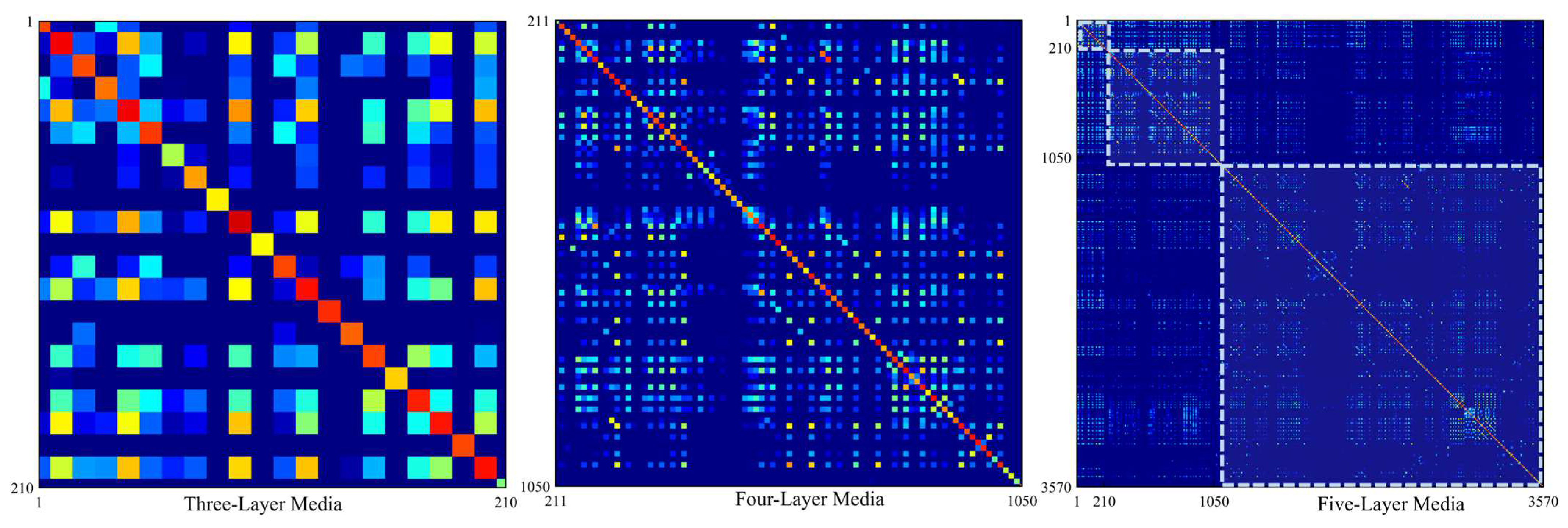
- Combinatorial encoding capacity scaling (210 codes for three layers, 2520 codes for five layers).
2. Materials and Methods
2.1. Theoretical Foundation
- = Dilatational potential function.
- = Shear potential function.
- = Dilatational wavenumber.
- = Shear wavenumber.
- = Lamé constants of the material.
- = Angular frequency.
- = Mode coefficients for layer .
- = Bessel and Neumann functions of order [21].
- = Cylindrical coordinates.
- = Scattering coefficients.
- = Hankel function of first kind.
- = Acoustic wavenumber in water.
- = Speed of sound in water.
- = Scattered sound pressure.
- = Incident sound pressure.
- = Scattered pressure is projected to 1 m (the standard reference).
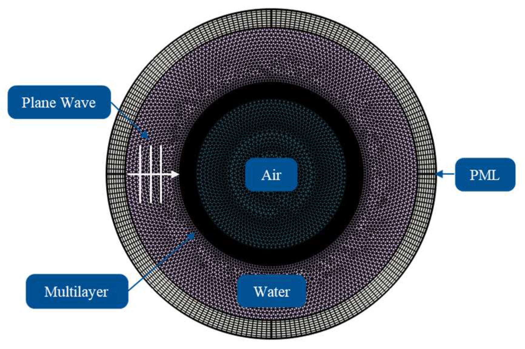
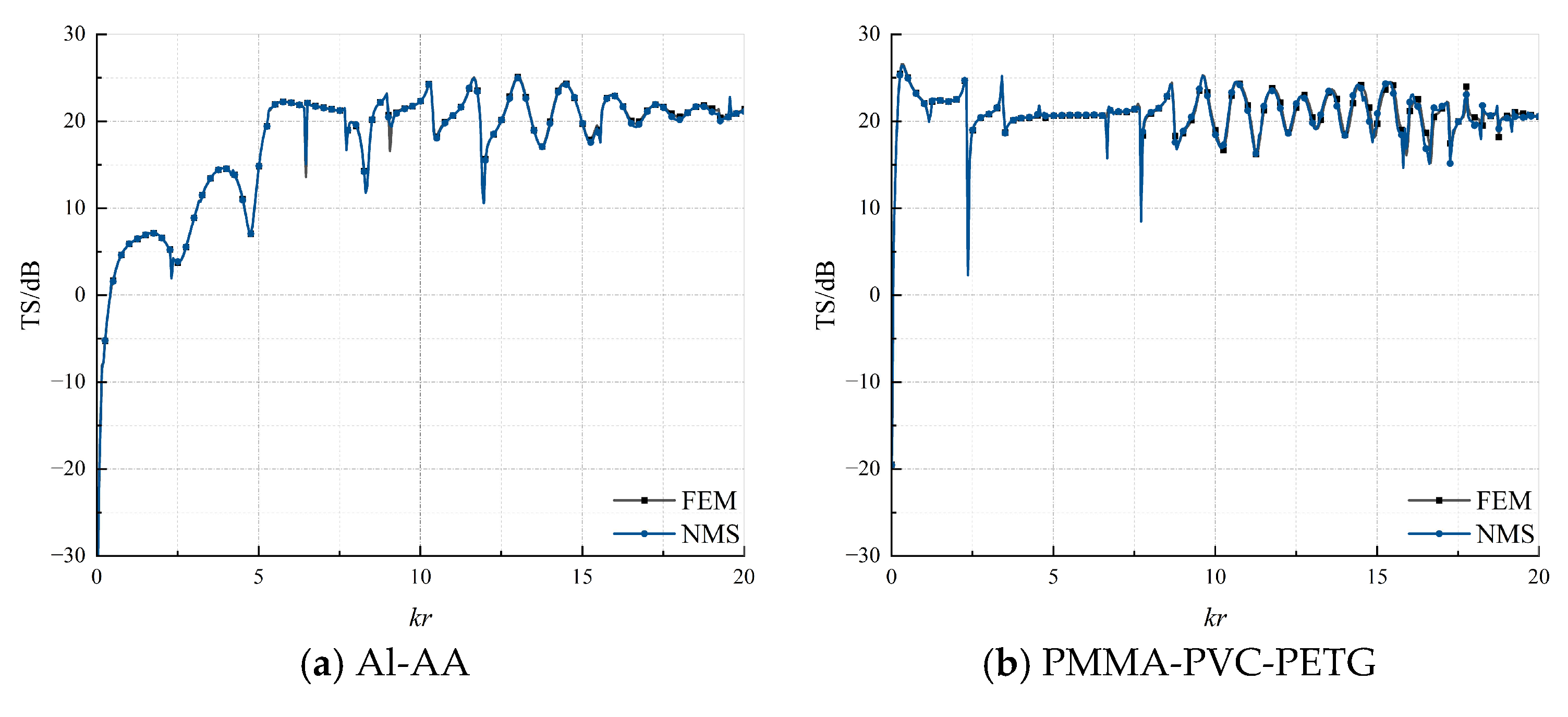
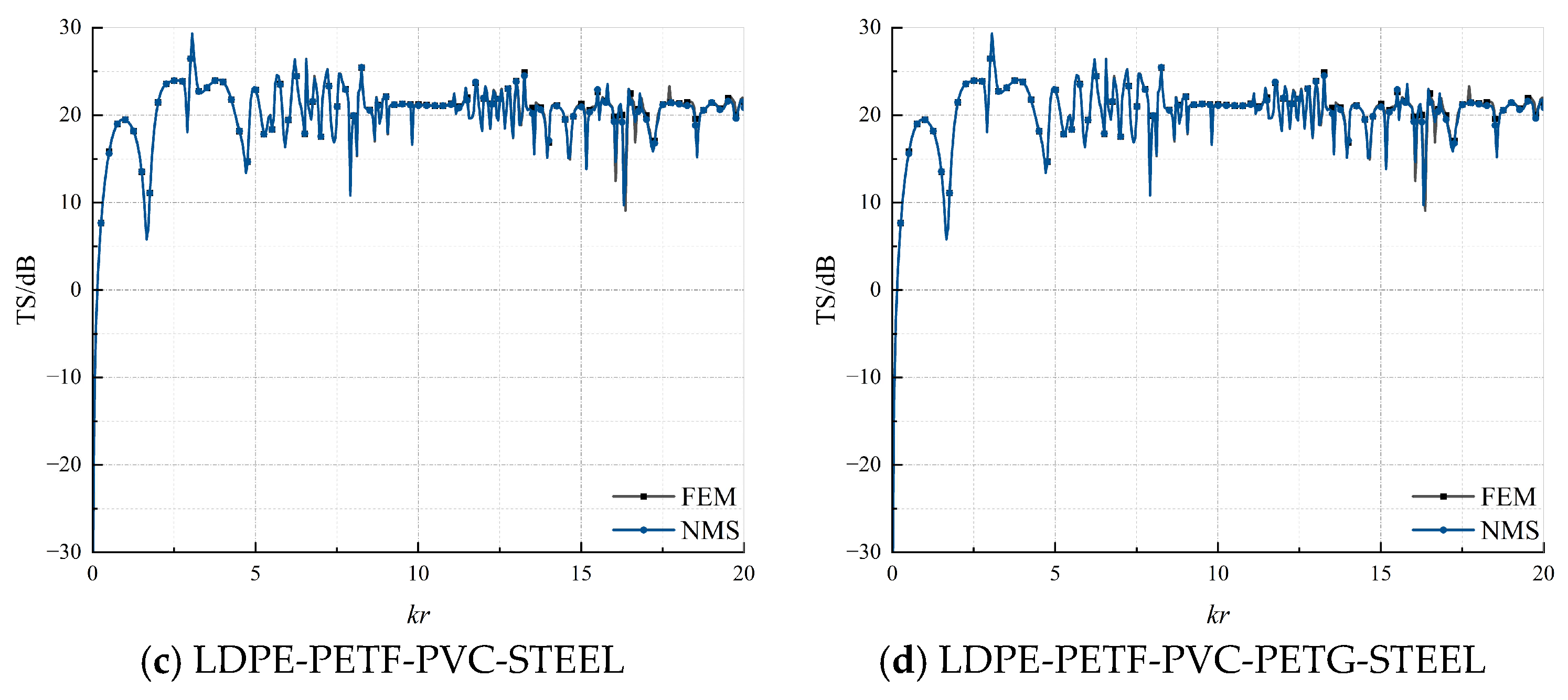
2.2. Numerical Verification
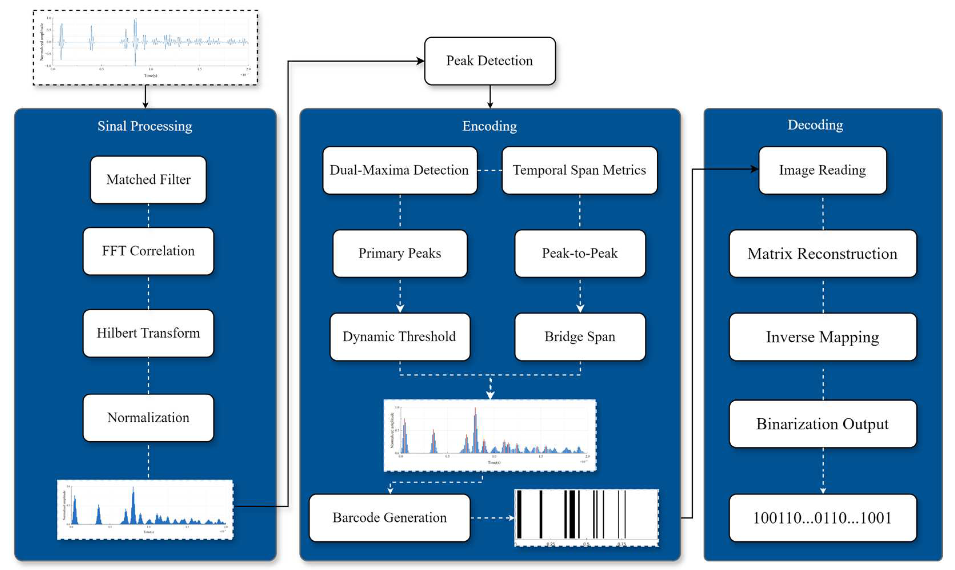
2.3. AlD Tag Generation Workflow
- = Bandwidth control parameter.
- = Time center of pulse.
- = Center frequency.
3. Verifications and Results
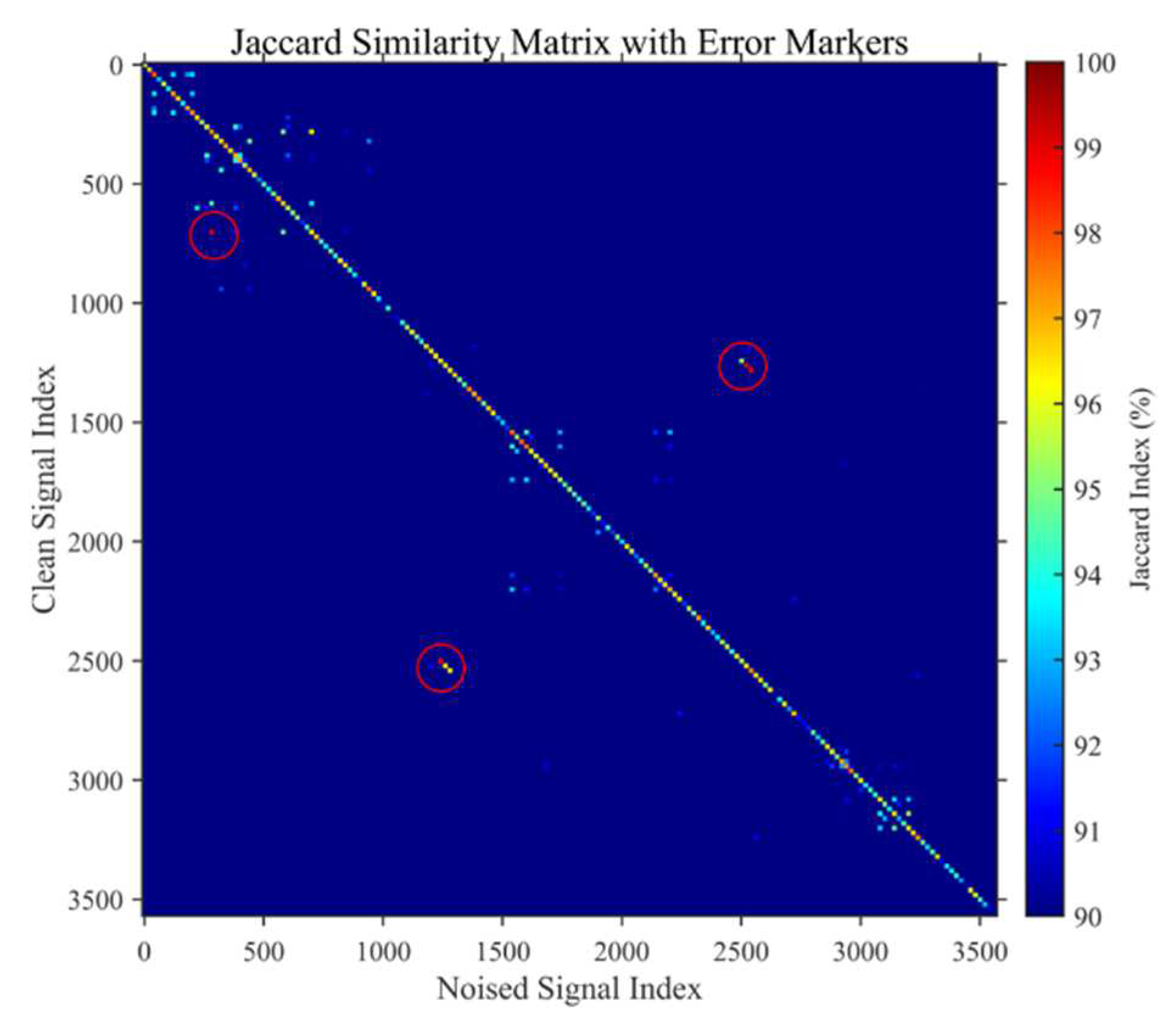
3.1. Effectiveness of AID Tags
- = Binary code sets from clean/noisy signals.
- = Cardinality of set.
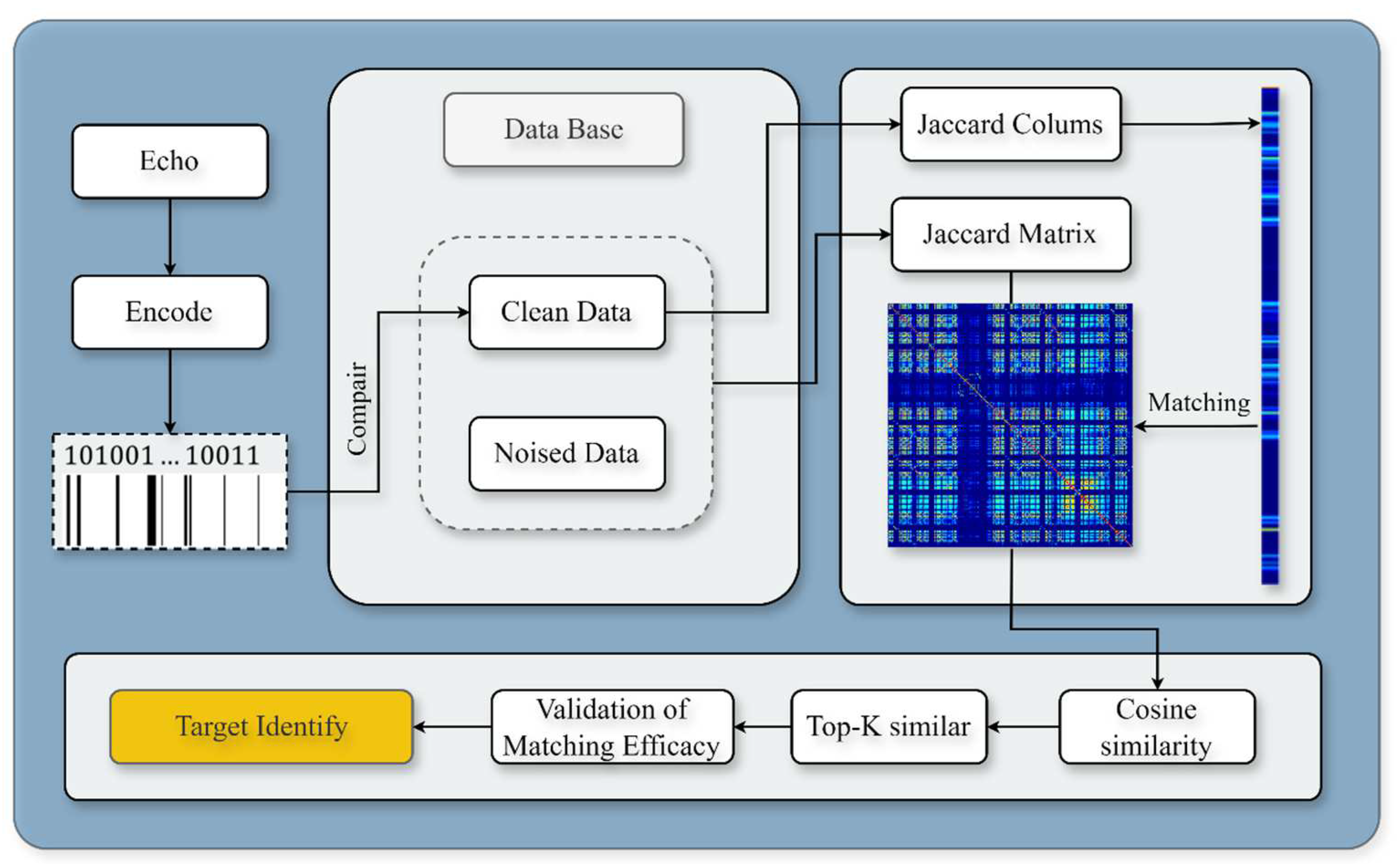
3.2. Target Recognition Methodology
4. Conclusions
Author Contributions
Funding
Institutional Review Board Statement
Informed Consent Statement
Data Availability Statement
Conflicts of Interest
Appendix A
References
- Wernli, R.L. AUV commercialization-who’s leading the pack? In Proceedings of the OCEANS 2000 MTS/IEEE Conference and Exhibition, Conference Proceedings (Cat. No.00CH37158), Providence, RI, USA, 11–14 September 2000; Volume 1, pp. 391–395. [Google Scholar]
- Yang, Y.; Xiao, Y.; Li, T. A survey of autonomous underwater vehicle formation: Performance, formation control, and communication capability. IEEE Commun. Surv. Tutor. 2021, 23, 815–841. [Google Scholar] [CrossRef]
- Gussen, C.M.; Diniz, P.S.; Campos, M.L.; Martins, W.A.; Costa, F.M.; Gois, J.N. A survey of underwater wireless communication technologies. J. Commun. Inf. Sys. 2016, 31, 242–255. [Google Scholar] [CrossRef]
- Maurelli, F.; Krupiński, S.; Xiang, X.; Petillot, Y. AUV localisation: A review of passive and active techniques. Int. J. Intell. Robot. Appl. 2022, 6, 246–269. [Google Scholar] [CrossRef]
- González-García, J.; Gómez-Espinosa, A.; Cuan-Urquizo, E.; García-Valdovinos, L.G.; Salgado-Jiménez, T.; Escobedo Cabello, J.A. Autonomous underwater vehicles: Localization, navigation, and communication for collaborative missions. Appl. Sci. 2020, 10, 1256. [Google Scholar] [CrossRef]
- Qin, J.; Li, M.; Li, D.; Zhong, J.; Yang, K. A survey on visual navigation and positioning for autonomous UUVs. Remote Sens. 2022, 14, 3794. [Google Scholar] [CrossRef]
- Aulinas, J.; Petillot, Y.; Salvi, J.; Lladó, X. The SLAM problem: A survey. In Artificial Intelligence Research and Development, Proceedings of the 11th International Conference of the Catalan Association for Artificial Intelligence, CCIA 2008, Sant Martí d’Empúries, Spain, 22–24 October 2008; IOS Press: Amsterdam, The Netherlands, 2008; pp. 363–371. [Google Scholar]
- Jung, J.; Li, J.H.; Choi, H.T.; Myung, H. Localization of AUVs using visual information of underwater structures and artificial landmarks. Intell. Serv. Robot. 2017, 10, 67–76. [Google Scholar] [CrossRef]
- Satish, A.; Nichols, B.; Trivett, D.; Sabra, K.G. Passive underwater acoustic tags using layered media. J. Acoust. Soc. Am. 2019, 145, EL84–EL89. [Google Scholar] [CrossRef]
- Satish, A.; Trivett, D.; Sabra, K.G. Omnidirectional passive acoustic identification tags for underwater navigation. J. Acoust. Soc. Am. 2020, 147, EL517–EL522. [Google Scholar] [CrossRef]
- Jalal, A.S.A. Passive RFID Tags. Wulfenia J. 2015, 22, 415–435. [Google Scholar]
- Bhardwaj, A.; Allam, A.; Erturk, A.; Sabra, K.G. Ultrasound-Powered Wireless Underwater Acoustic Identification Tags for Backscatter Communication. IEEE Trans. Ultrason. Ferroelectr. Freq. Control 2023, 71, 304–313. [Google Scholar] [CrossRef]
- Islas-Cital, A.; Atkins, P.; Gardner, S.; Tiltman, C. Performance of an enhanced passive sonar reflector SonarBell: A practical technology for underwater positioning. Underw. Technol. 2013, 31, 113–122. [Google Scholar] [CrossRef]
- Zhou, Y.; Fan, J.; Huang, J.; Wang, B. Passive underwater acoustic barcodes using Rayleigh wave resonance. J. Appl. Phys. 2022, 131, 124901. [Google Scholar] [CrossRef]
- Satish, A.; Sabra, K.G. Passive underwater acoustic identification tags using multi-layered shells. J. Acoust. Soc. Am. 2021, 149, 3387–3405. [Google Scholar] [PubMed]
- Kepros, E.; Chahal, P. Ultra Low Power Wireless Ultrasonic Sensor Tag with ID. IEEE Sens. J. 2025, 25, 8823–8827. [Google Scholar]
- Somaan, N.; Bhardwaj, A.; Sabra, K.G. Passive underwater Acoustic IDentification (AID) tags for enhancing Autonomous Underwater Vehicle (AUV) navigation during docking or homing operations. J. Acoust. Soc. Am. 2023, 153 (Suppl. S3), A345. [Google Scholar]
- Somaan, N.; Bhardwaj, A.; Sabra, K.G. Passive acoustic identification tags for marking underwater docking stations. JASA Express Lett. 2024, 4, 126001. [Google Scholar] [CrossRef]
- Ding, D.; Chen, C.X.; Kong, H.M.; Fan, J.; Peng, Z.L. Acoustic encoding of high-frequency time-domain echoes from layered elastic spherical shells in water. Appl. Acoust. 2023, 42, 781–791. [Google Scholar]
- Zhou, F.; Fan, J.; Wang, B.; Zhou, Y.; Huang, J. Acoustic barcode based on the acoustic scattering characteristics of underwater targets. Appl. Acoust. 2022, 189, 108607. [Google Scholar]
- Gaunaurd, G.C. Sonar cross section of a coated hollow cylinder in water. J. Acoust. Soc. Am. 1977, 61, 360–368. [Google Scholar] [CrossRef]
- Martins, N. A Time Frequency Approach to Blind Deconvolution in Multipath Underwater Channels. Master’s Thesis, Universidade do Algarve Faro, Portugal, 2001. [Google Scholar]
- Wenz, G.M. Acoustic ambient noise in the ocean: Spectra and sources. J. Acoust. Soc. Am. 1962, 34, 1936–1956. [Google Scholar]
- Royston, P. Approximating the Shapiro-Wilk W-test for non-normality. Stat. Comput. 1992, 2, 117–119. [Google Scholar] [CrossRef]
- Lucas, E.; Wang, Z. Performance prediction of underwater acoustic communications based on channel impulse responses. Appl. Sci. 2022, 12, 1086. [Google Scholar] [CrossRef]
- Bag, S.; Kumar, S.K.; Tiwari, M.K. An efficient recommendation generation using relevant Jaccard similarity. Inf. Sci. 2019, 483, 53–64. [Google Scholar] [CrossRef]
- Zhu, D.; Li, Q.; He, X.; Wang, R.; Liu, Q. Preparation of highly dewetted porous steel for shallow water AUV based on laser ablation method. Appl. Surf. Sci. 2024, 652, 159261. [Google Scholar] [CrossRef]
- Efron, B.; Tibshirani, R.J. An Introduction to the Bootstrap; Chapman and Hall/CRC: Boca Raton, FL, USA, 1994. [Google Scholar]
- Huang, M.; Chen, D.; Feng, D. The Fruit Recognition and Evaluation Method Based on Multi-Model Collaboration. Appl. Sci. 2025, 15, 994. [Google Scholar] [CrossRef]
- Adomavicius, G.; Zhang, J. Classification, ranking, and top-K stability of recommendation algorithms. INFORMS J. Comput. 2016, 28, 129–147. [Google Scholar] [CrossRef]


| Material Names | Density | Young’s Modulus | Poisson’s Ratio | Longitudinal Velocity | Characteristic Impedance (Megarayleighs) |
|---|---|---|---|---|---|
| Water | 1000 | / | / | 1480 | 1.48 |
| Air | 1.2 | / | / | 344 | 0.41 × 10⁻³ |
| Polymethyl Methacrylate (PMMA) | 1180 | 2.8 | 0.38 | 2108 | 2.49 |
| Polyvinyl Chloride (PVC) | 1400 | 3 | 0.38 | 2003 | 2.80 |
| Polytetrafluoroethylene (PTFE) | 2200 | 0.4 | 0.37 | 567 | 1.25 |
| Polyethylene Terephthalate Glycol-modified (PETG) | 1270 | 2 | 0.37 | 1669 | 2.12 |
| High-Density Polyethylene (HDPE) | 970 | 1.5 | 0.4 | 1820 | 1.77 |
| Low-Density Polyethylene (LDPE) | 910 | 0.1 | 0.45 | 646 | 0.59 |
| Acrylic Acid (AA) | 1190 | 3.2 | 0.35 | 2078 | 2.47 |
| Aluminum (Al) | 2700 | 70 | 0.33 | 4032 | 10.89 |
| Structural steel | 7850 | 200 | 0.3 | 5856 | 45.97 |
| Configuration Name | Environmental Parameter |
|---|---|
| CPU | AMD Ryzen 7 5800H (AMD, Santa Clara, CA, USA) |
| GPU | NVIDIA GeForce RTX 3070 Laptop (NVIDIA Corporation, Santa Clara, CA, USA) |
| RAM | 32 GB DDR4 (3200 MHz) |
| COMSOL Multiphysics | 6.2 |
| MATLAB | R2024b |
| PMMA-PTFE-LDPE |  |  | 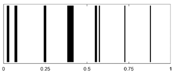 |
| PMMA-LDPE-PTFE | 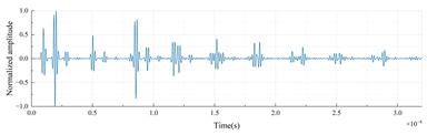 | 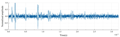 | 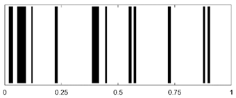 |
| PTFE-PMMA-LDPE |  |  |  |
| PTFE-LDPE-PMMA |  |  |  |
| LDPE-PMMA-PTFE |  | 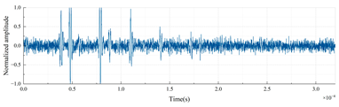 | 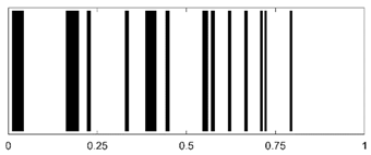 |
| LDPE-PTFE-PMMA |  |  |  |
| Comparison Data | MJI (%) |
|---|---|
| PMMA-PTFE-LDPE | 99.02 |
| PMMA-LDPE-PTFE | 98.24 |
| PTFE-LDPE-PMMA | 98.71 |
| PTFE-PMMA-LDPE | 98.27 |
| LDPE-PMMA-PTFE | 97.58 |
| LDPE-PTFE-PMMA | 97.40 |
| Mean | 98.20 |
| Structural Steel MJI (%) | Aluminum MJI (%) |
|---|---|
| 98.54 | 98.76 |
| 98.31 | 98.24 |
| 98.97 | 98.60 |
| 98.64 | 98.73 |
| 97.17 | 96.98 |
| 97.61 | 97.92 |
| 98.21 (mean) | 98.21 (mean) |
| Number of Material Layers | Cylinder Radius | Quantity |
|---|---|---|
| 3 | 0.25 | 210 |
| 4 | 0.26 | 840 |
| 5 | 0.27 | 2520 |
| Number of Material Layers | Lower Bound | Upper Bound |
|---|---|---|
| 3 | 95.67 | 96.11 |
| 4 | 95.03 | 95.28 |
| 5 | 94.46 | 94.60 |
| All | 94.70 | 94.82 |
Disclaimer/Publisher’s Note: The statements, opinions and data contained in all publications are solely those of the individual author(s) and contributor(s) and not of MDPI and/or the editor(s). MDPI and/or the editor(s) disclaim responsibility for any injury to people or property resulting from any ideas, methods, instructions or products referred to in the content. |
© 2025 by the authors. Licensee MDPI, Basel, Switzerland. This article is an open access article distributed under the terms and conditions of the Creative Commons Attribution (CC BY) license (https://creativecommons.org/licenses/by/4.0/).
Share and Cite
Dai, Z.; Peng, Z.; Xu, S. High-Frequency Passive Acoustic Recognition in Underwater Environments: Echo-Based Coding for Layered Elastic Shells. Appl. Sci. 2025, 15, 3698. https://doi.org/10.3390/app15073698
Dai Z, Peng Z, Xu S. High-Frequency Passive Acoustic Recognition in Underwater Environments: Echo-Based Coding for Layered Elastic Shells. Applied Sciences. 2025; 15(7):3698. https://doi.org/10.3390/app15073698
Chicago/Turabian StyleDai, Zixuan, Zilong Peng, and Suchen Xu. 2025. "High-Frequency Passive Acoustic Recognition in Underwater Environments: Echo-Based Coding for Layered Elastic Shells" Applied Sciences 15, no. 7: 3698. https://doi.org/10.3390/app15073698
APA StyleDai, Z., Peng, Z., & Xu, S. (2025). High-Frequency Passive Acoustic Recognition in Underwater Environments: Echo-Based Coding for Layered Elastic Shells. Applied Sciences, 15(7), 3698. https://doi.org/10.3390/app15073698