Article

A Layered Software Architecture for the Development of Smart Mobile Distributed Systems Oriented to the Management of Emergency Cases

by
Lizbeth Yesenia Contreras Rivas
1,
Eduardo López Domínguez
2,*,
Yesenia Hernández Velázquez
1,
Saúl Domínguez Isidro
3,
María Auxilio Medina Nieto
4 and
Jorge De La Calleja
4
1
Laboratorio Nacional de Informática Avanzada, Veracruz 91100, Mexico
2
Departamento de Computación, Centro de Investigación y de Estudios Avanzados del Instituto Politécnico Nacional, Ciudad de México 07360, Mexico
3
Faculty of Statistics and Informatics, Universidad Veracruzana, Veracruz 91020, Mexico
4
Postgraduate Department, Universidad Politécnica de Puebla, Puebla 72640, Mexico
*
Author to whom correspondence should be addressed.
Appl. Sci. 2025, 15(7), 3664; https://doi.org/10.3390/app15073664
Submission received: 18 December 2024 / Revised: 26 February 2025 / Accepted: 24 March 2025 / Published: 27 March 2025

Abstract

:
Smart mobile distributed systems (SMDSs) oriented to managing emergency cases (ECs) have become a helpful support tool in case of earthquakes at government and higher education institutions (GHEIs). This fact has motivated various works to propose SMDSs that are focused on managing ECs; however, many fail to address all essential requirements for effective managing and streamlining of the activities that must be carried out before, during, and after an earthquake occurs at GHEIs, resulting in suboptimal design decisions. In addition, none of these works proposes a reference software architecture that guides the development of these systems. That has given rise to issues, such as lack of standardization and low quality of the developed systems. This work presents a software architecture to develop SMDSs focused on managing the activities of people and members of the brigades in case of earthquakes at GHEIs. The proposed software architecture was evaluated based on four main aspects: correctness and coverage of desirable requirements, functional suitability, usability assessment, and validation and verification of the reference architecture elements. The results show that our software architecture provides suitable architectural support for developing SMDSs oriented to managing ECs, which meets the needed requirements.

1. Introduction

Due to its geographical location, Mexico is vulnerable to different natural phenomena that can cause catastrophes. The Mexican territory is on five tectonic plates: the Caribbean, Pacific, North America, Rivera, and Cocos. The mobility of these plates causes friction forces that prevent the displacement of one concerning the other, sometimes causing a violent rupture and releasing accumulated energy; this phenomenon is known as an earthquake [1,2,3]. More than 100,000 seismic movements have occurred in recent years, of which 19 are classified at a magnitude between six and nine degrees on the Richter scale [4]. Given these facts, government actions have focused on informing and training the population through civil protection programs. The Mexican government and higher education institutions (GHEIs) have a civil protection program [5,6], which details the actions that must be carried out before, during, and after a disaster. The Mexican civil protection program includes brigades, which are comprised of people responsible for activating the actions within the prevention, aid, and rescue subprograms [5,6]. At least two institution elements compose the brigades, and there are four brigades: (1) evacuation, (2) search and rescue, (3) first aid and prevention, and (4) firefighting [5,6]. During the earthquake, the relief subprogram is activated where the following actions are carried out by people and brigades [7,8]: Stay away from windows and objects that could fall, locate the personnel of the evacuation brigade, lead the staff along the established route to the security zones, check that the institution is fully evacuated, and organize and control the personnel in the security zones.
On the other hand, the recovery subprogram is activated after an earthquake, involving the following activities [7,8]: conducting a census of evacuees in security zones, identifying missing individuals, and locating and rescuing potential victims. These activities are generally performed manually, leading to the following drawbacks:
  • Regarding the census of evacuees and missing individuals, this activity involves conducting a roll call of people in security zones using a printed format and compiling a census. Additionally, a report on absent academic staff and students is generated. This process requires an up-to-date list of students and faculty present on the premises at the time of the event. Since it must be carried out in each security zone within the institution, the time required is proportional to the number of academic staff.
  • The procedure for locating and rescuing potential victims begins by determining the absent person’s designated work area and searching for them there. If they are not found, the responsible brigade proceeds to check common areas. A major challenge in this process is the delay in locating individuals, particularly in institutions with multiple buildings, which can even result in loss of life due to a late response. The total time for these activities should not exceed 20 min.
This research aims to support the management and coordination of activities carried out by individuals and members of evacuation, search, and rescue brigades before, during, and after an earthquake at GHEIs. The use of Information and Communication Technology (ICT) in emergency situations enhances the response times, improves the effectiveness and efficiency of action protocols, and optimizes the coordination of the involved personnel [9]. Most individuals have access to ICT through mobile devices, with smartphones being the most prevalent [10].
Several studies [11,12,13,14,15,16,17,18,19,20,21,22,23,24,25] have proposed smart mobile distributed systems (SMDSs) for managing emergency cases (EC) such as earthquakes, each offering different characteristics and functionalities. However, these works fail to comprehensively address the essential requirements for effectively managing and streamlining activities before, during, and after an earthquake at a GHEI, leading to suboptimal architectural design decisions. Suboptimal architectural design decisions in software systems result in SMDS solutions that only partially fulfill the objectives required by victims and evacuation, search, and rescue brigades.
Another significant limitation of the existing studies [11,12,13,14,15,16,17,18,19,20,21,22,23,24,25] is the absence of a reference software architecture to guide the development of these systems. This lack of standardization has led to issues such as low system quality in terms of requirement correctness and coverage, ultimately limiting the implementation and adoption of the proposed systems in different contexts [26].
This paper proposes a layered and tiered software architecture for developing smart mobile distributed systems aimed at managing the activities of individuals and brigade members during earthquakes at GHEIs. Our software architecture was designed and developed based on the requirements established in the Mexican National Civil Protection Program, the school emergency programs of higher education institutions, and an analysis of the services described in related works [11,12,13,14,15,16,17,18,19,20,21,22,23,24,25].
Our architecture was evaluated using four approaches. The first approach assesses the correctness and coverage of the requirements to ensure that the proposed software architecture addresses the necessary specifications. The second approach evaluates the quality of the resulting product in terms of functional suitability. In this case, an intelligent mobile distributed system was developed to manage the activities of evacuation, search, and rescue brigades, as well as victims, before, during, and after an earthquake, following the design of the proposed software architecture. Functional suitability tests were conducted using simulated scenarios. The third approach assesses the usability of the developed prototype through a controlled laboratory study. Finally, the fourth approach validates and verifies that the proposed software architecture includes all key infrastructure, domains, applications, and cross-cutting components of a reference architecture based on the RAModel model [26].
Based on the results, our software architecture provides robust architectural support for the development of smart mobile distributed systems designed to manage emergency cases at GHEIs while meeting the required specifications and quality attributes.
The remainder of this paper is structured as follows: Section 2 describes the desirable requirements, design, instantiation, and evaluation of the proposed software architecture. Section 3 reviews related work. Section 4 presents the verification and comparison of the desirable requirements considered in related studies and our work. Finally, Section 5 concludes with a discussion of conclusions and future research directions.

2. Proposed Software Architecture

The research approach used in this work follows the design science paradigm. The design science paradigm involves proposing an artifact-based solution to a practical problem of general interest [27]. Therefore, the methodology followed in this work was divided into four stages: (1) Software architecture requirements, (2) design of the software architecture, (3) instantiation of the software architecture, and (4) evaluation of the proposed software architecture. In the first stage, the main requirements were obtained through the review and analysis of the following elements: official civil protection documentation, school emergency response programs, interviews with users who are members of the internal civil protection unit at higher education institutions, and the services described in the related work section. The second stage focused on creating the conceptual design and component view of the proposed software architecture. The instantiation stage demonstrated the application of the proposed software architecture by developing a system designed to manage evacuation, search, and rescue brigades, as well as victim activities, before, during, and after an earthquake. Finally, in the fourth stage, the proposed software architecture was evaluated based on functional suitability, usability, correctness, and coverage of desirable requirements. The following sections describe the artifacts produced at each stage of our methodology.

2.1. Software Architecture Requirements

In this section, we present the requirements identified and considered for the design and development of our software architecture based on the analysis of official civil protection documentation, the review of the school emergency response program, interviews with users who are members of the internal civil protection unit at higher education institutions, and an analysis of the services described in the state-of-the-art [28]. We classify the identified requirements according to the type of user. The main requirements for individuals or victims are described first:
  • REQ1—Authenticate in the system: The user must authenticate with his username/email and a password.
  • REQ2—Recover password: The user must recover his password by entering his email.
  • REQ3—Logout: The user must log out of the system.
  • REQ4—Register: The user must register in the system with their full name, username/email, telephone, full address, emergency contact, registration or employee ID, RFC, profession, position held, affiliation area, floor, telephone office, diseases, treatment, blood type, and allergies. Regarding data privacy, in our case, a privacy notice is provided to users. This document informs the user of the specific processing of their personal data within the exclusive framework of the services of the proposed system.
  • REQ5—Modify information: Users must modify their information in the system with their email, telephone, full address, emergency contact, RFC, profession, position performed, affiliation area, floor, office telephone, diseases, treatment, blood type, and allergies.
  • REQ6—Visualize the safe zones: The user must visualize the safe zones of the building.
  • REQ7—View glossary of signs: The user must see a glossary of the signs that the building has.
  • REQ8—View the directory of external support institutions: The user must view the directory of external support institutions, such as the institution’s name and telephone number.
  • REQ9—View user manual of security equipment: The user is required to see the user manuals of the different security equipment.
  • REQ10—Send location to search and rescue brigades: Users must send a location notification to search and rescue brigades with their location.
  • REQ11—Send a message to the search and rescue brigades: The user must send a message to the search and rescue brigades.
  • REQ12—Answer health questionnaire: The user answers with Yes or No on a questionnaire about their state of health.
  • REQ13—Report a problem: The user can report a problem, such as a fire, gas leak, or breakdown, through their respective buttons. The report can be canceled within 10 s. Otherwise, the system will send a notification to the brigades of the problem’s location.
  • REQ14—Visualize the location of the support material: The user must visualize the location of the support materials such as fire extinguishers, first aid kits, etc.
  • Regarding the evacuation brigade, the following requirements were defined:
  • REQ15—Show the list of routes to the closest exits: The rescuer must see the closest route to the exit. Simple indications on the direction to follow.
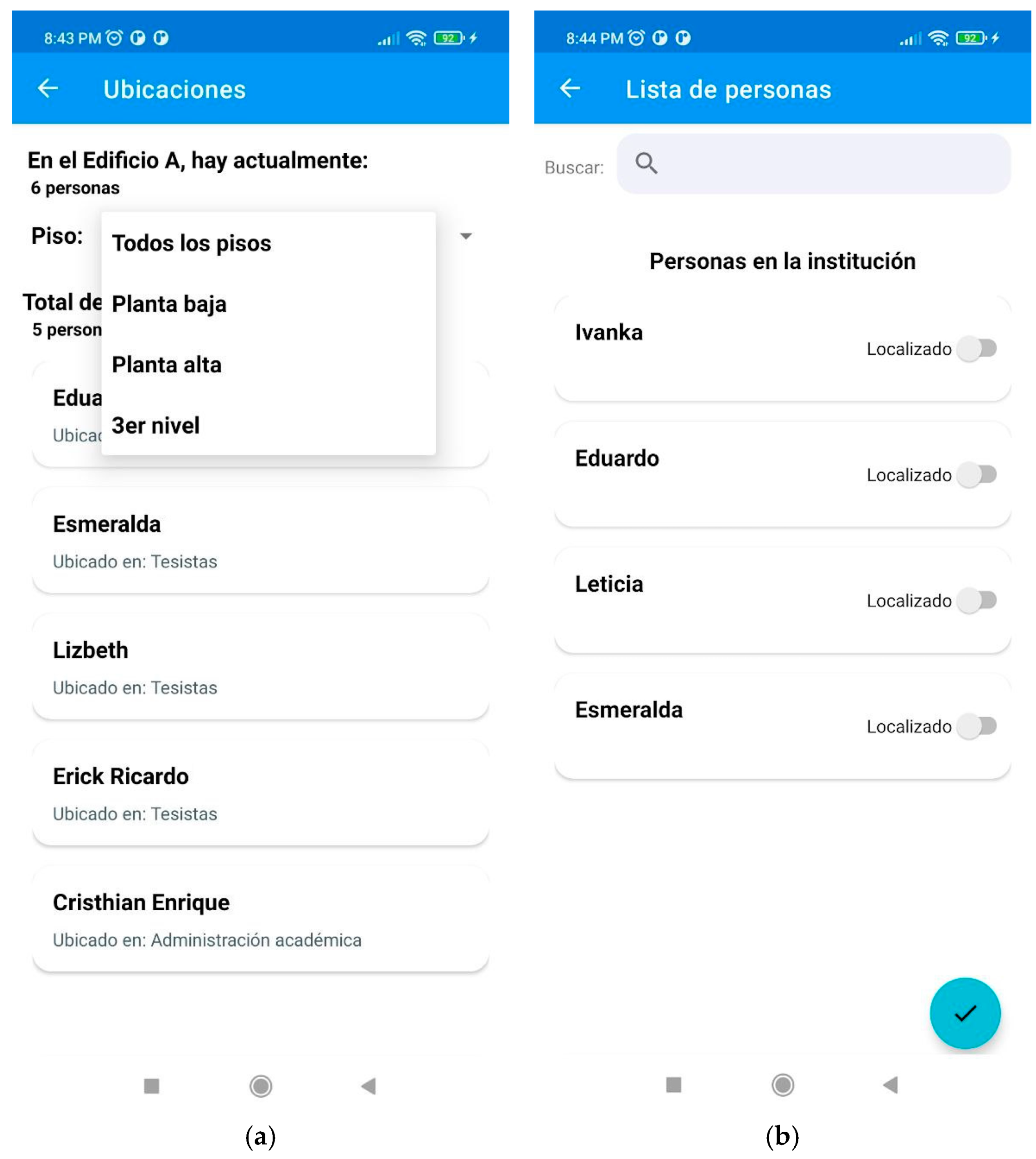
  • REQ16—View users inside the building: The rescuer must see if there are users in the building; they can be viewed by building and floor, through a map or a list by building, floor, and department.
  • REQ17—See a list of academic staff, students, and outsiders: The rescuer must see the list of academic staff and students inside the building at the time of the earthquake. The list should have relevant information such as a full name, phone number, department, or room, and if you have a chronic illness.
  • REQ18—See details of the selected person: The rescuer requires additional information such as an emergency contact, address, and a photograph.
  • REQ19—Identify academic staff, students, and external people as located or absent: The rescuer must identify academic staff, students, and external people as located if they are within a safe zone; otherwise, they can be marked absent.
  • REQ20—Classify building departments: The rescuer must identify each building department as safe for entry. In this case, you can see the building and the department’s name and classify it as safe or not.
  • REQ21—View the report on the building: The rescuer must see the report on the state of the building.
In the case of the search and rescue brigade, the following requirements were defined:
  • REQ22—Closing off evacuated areas: The rescuer must determine if each apartment in the building has already been evacuated and can be registered as closed. The building name, department name, and status will be displayed.
  • REQ23—View the report on closed areas: The rescuer must see the report on the areas that have already been closed because they were evacuated.
  • REQ24—View the first aid manual: The rescuer must consult the first aid manuals if it is necessary to apply them. It is displayed through a series of questions such as the gender of the person, age, the situation of the person (conscious or unconscious), select everything that applies from a list of the most common symptoms to various emergency cases so that the system can diagnose the type of emergency and show the series of steps to follow.
  • REQ25—View the report of absent people: The rescuer must consult the list of people out of the security zones. The list must have information such as a full name, telephone number, department, or room.
  • REQ26—Visualize the people inside the building through a plan of the building: The rescuer must consult the people inside the building. You can choose the building you want to view.
  • REQ27—See a specific user: The rescuer must see a specific user inside the building. The username and location (department or area) will be visible.
  • REQ28—Send a message to a specific user: The rescuer should interact through messages with a specific user.
  • REQ29—View the emergency list: The rescuer must see the emergency list that users report, for example, fires or that the user requires help.
  • REQ30—Generate annex 14 of civil protection: The rescuer must fill out the format of annex 14 that requests civil protection after an earthquake.
Finally, due to the development approach of emergency case management systems on mobile distributed systems, the following requirements were considered [29,30,31]:
  • REQ31—Heterogeneity.
  • REQ32—Robustness against disconnections.
  • REQ33—Lightness.
  • REQ34—Extensibility.
  • REQ35—Modularity.
  • REQ36—Usability.
  • REQ37—Security.
  • REQ38—Ease of verification and maintenance.

2.2. Software Architecture Design

In this section, we describe the conceptual, component, and deployment views of the proposed software architecture in this study.

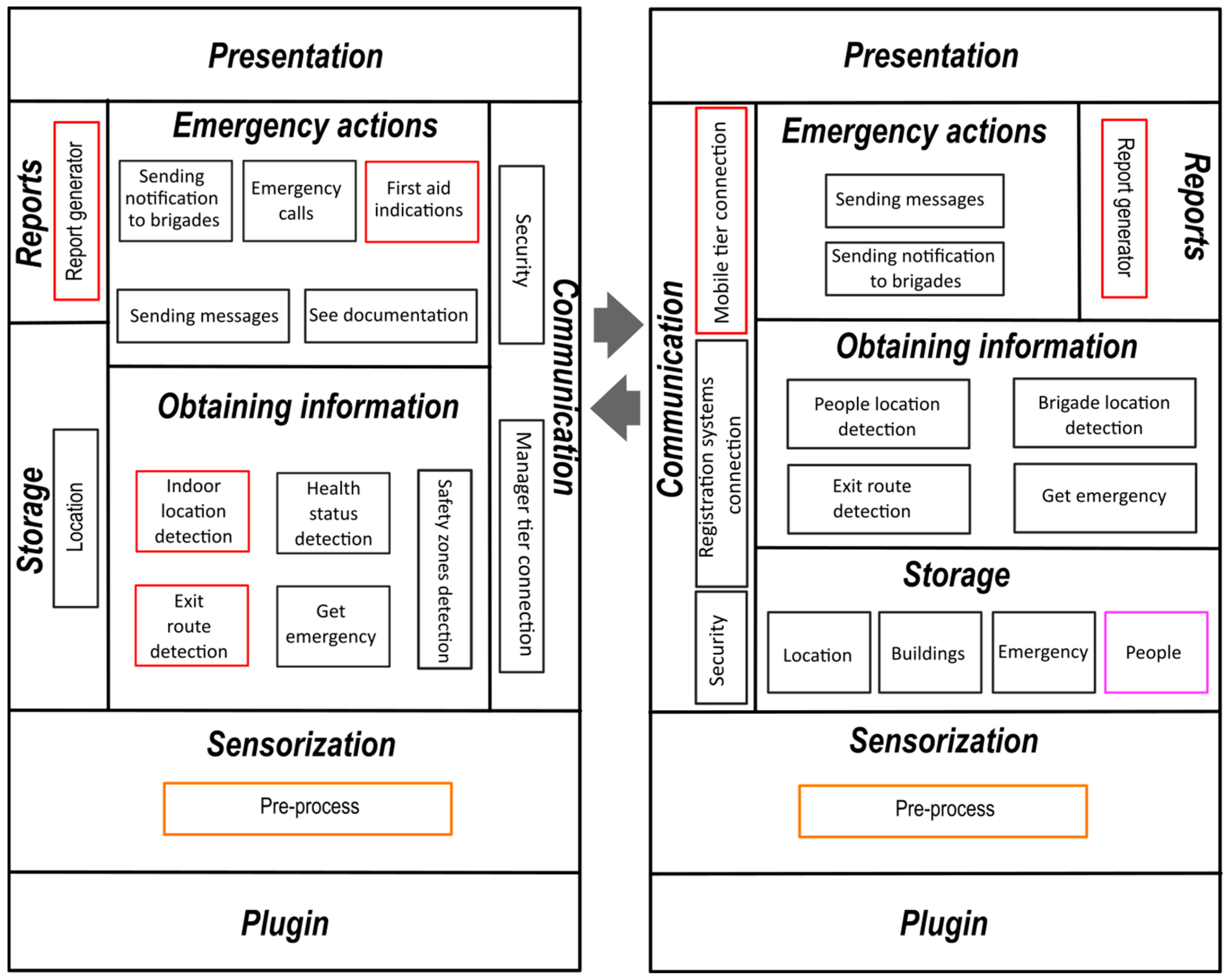
2.2.1. Conceptual View

Based on the identified requirements, we designed a layered and tiered software architecture to develop smart mobile distributed systems for managing and streamlining the activities of individuals and members of evacuation, search, and rescue brigades in emergency cases such as earthquakes or fires (see Figure 1). The proposed software architecture is based on the general approach presented in [30] for two-tier software architectures for context-aware distributed mobile systems, and we also incorporated key ideas from our conceptual design that are related to information gathering and processing, as described in [31]. In our software architecture, tiers complement layers; services are modeled in vertical abstract layers, while tiers handle the functionality of a specific layer within nodes. Each layer is independent since it performs a specific service. The mobile tier is intended to work on devices with limited storage and processing capabilities (for instance, mobile devices). On the other hand, the manager/administrator tier is designed to work on devices with greater storage and processing capacity, such as servers. Therefore, the workload is higher in the administrator tier than in the mobile tier. Although layers exist in both tiers and have the same name, their services depend on the device’s hardware.
The layers and components of the mobile tier are described below:
Plugin layer: This layer refers to plugins, which are independent components that are responsible for collecting sensor data from various hardware components, such as retrieving information from available Wi-Fi networks that the mobile device can detect.
Sensorization layer: It is responsible for managing the different plugins involved in the administration and control system of the activities of the brigades. This layer contains a component whose function is as follows:
  • Pre-process layer: It is responsible for eliminating out-of-range values and converting the format for the upper layers.
Storage layer: It saves helpful information such as the last location and authentication credentials.
Information gathering layer: It is responsible for extracting the information that the user needs. This layer is made up of the following components:
  • Indoor location detection module: This module is responsible for identifying the person’s location inside a building.
  • Exit route detection module: This module identifies the route to the closest exit.
  • Health status detection module. This module is responsible for determining the health status of the person.
  • Emergency obtaining module: This module is responsible for obtaining the emergency that the person is indicating.
  • Security zone detection module: This module is responsible for obtaining the location of security zones.
Report layer: This layer can capture the information required to generate the reports that the brigades must pass on to the civil protection internal unit (CPIU) coordinator or civil protection.
Emergency actions layer: It controls functionalities such as sending notifications to the brigades, emergency calls, etc. The modules that this layer contains are:
  • Module for sending notifications to the brigades: This module oversees notifying the brigades about a possible problem indicated by the person.
  • Emergency call module: This module generates an emergency call if the user requires it.
  • First aid instructions module: It is responsible for generating first aid indications if it is required.
  • Module for sending messages: This module is responsible for sending messages between a person and the brigade.
Communication layer: This layer maintains security and communication with the administrator tier. The modules that this layer contains are:
  • Security module: This module oversees the security of access to the system.
  • Connection module between the tiers: This module maintains a connection between the administrator and mobile tiers.
Presentation layer: This layer provides a system interface for viewing information or performing tasks.
On the other hand, the layers and components of the manager tier of our architecture are described below:
Plugin layer: It obtains the sensorization of different data from the plugins. Plugins can be physical, logical, or virtual.
Sensorization layer: It is responsible for managing the different plugins involved in the administration and control systems of the activities of the brigades. This layer contains a component whose function is as follows:
  • Pre-process layer: It is responsible for eliminating out-of-range values and converting the format for the upper layers.
Storage layer: It is responsible for saving information such as the location of all people, emergency reports, and information on buildings and people. This layer is made up of four main components:
  • Location module: It is responsible for saving information on the location of people and brigades.
  • Emergency module: It oversees keeping the list of emergencies that people indicate.
  • Buildings module: It saves all the information related to buildings, such as the name, departments, floor, support material, etc.
  • People module: This module is responsible for keeping a list of people inside the building during an emergency.
Information gathering layer: It is responsible for extracting the information that the user needs. In this layer, the components perform the following functions:
  • Indoor location detection module of people: This module is responsible for extracting the indoor location of the people currently in the building.
  • Module for detecting the location of the interiors of the brigades: This module is responsible for extracting the location indoors of the brigades that are currently in the building.
  • Exit route detection module: This module extracts the route to the nearest exit.
  • Emergency obtaining module: This module is responsible for obtaining the emergency that the person is indicating.
Report layer: It is responsible for generating the reports that the brigades need to pass on to the CPIU coordinator or civil protection.
Emergency actions layer: It controls functionalities such as sending notifications to the brigades, messages, etc. The modules that this layer contains are:
  • Module for sending notifications to the brigades: It oversees notifying the brigades about a possible problem indicated by the person.
  • Message-sending module: This module is responsible for sending messages between a person and the brigade.
Communication layer: This layer maintains communication and security with the mobile tier. The modules that this layer contains are:
  • Security module: This module oversees the security of access to the system.
  • Connection module between tiers: This module maintains a connection between the manager and mobile tiers.
Presentation layer: It provides a system interface for viewing information or performing tasks.

2.2.2. Component View

This section presents the component diagrams of both tiers. The component diagrams for each tier illustrate the conceptual design elements of our architecture. These diagrams are based on software architectural patterns and recommended technologies based on specialized literature.

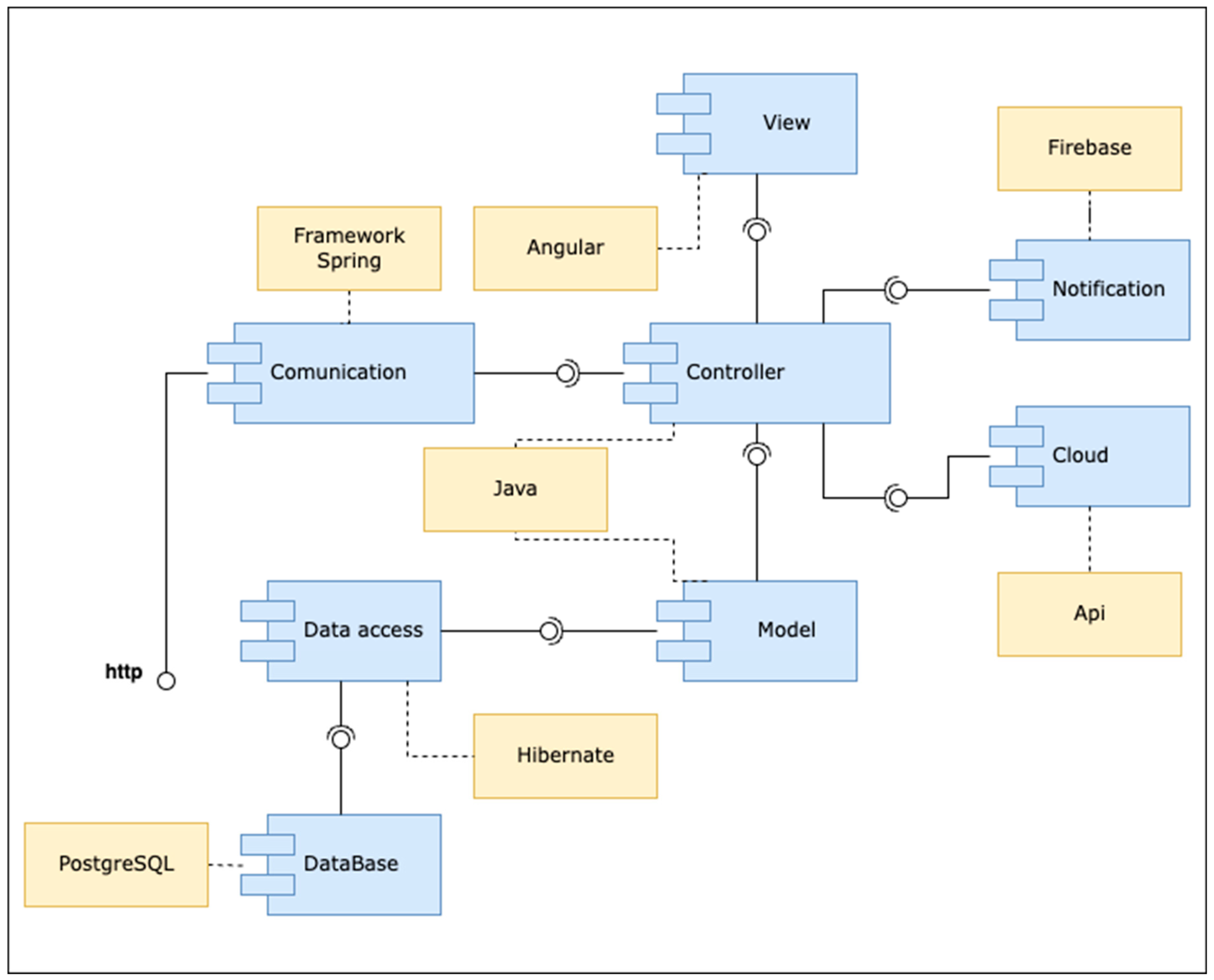
Component Diagram for the Manager/Administrator Tier

Figure 2 shows the component diagram for the manager/administrator tier. This diagram follows the Model View Controller (MVC) architectural pattern, which separates the data and business logic from the user interface and the module responsible for managing events.
Within the component diagram shown in Figure 2, the following components were defined:
  • View: This component manages the graphical interface with which the user will interact.
  • Model: This component maps the information stored or extracted from the server database.
  • Controller: This controls the application’s logic and responds to requests from the graphical interface or some other process.
  • Cloud: This is a component that allows the management of the information found in a server in the cloud.
  • Notification: This provides the necessary mechanisms to generate notifications that reach users to inform them of a message or an emergency.
  • Data Access: This provides access and control of the information in the database.
  • Database: This controls the database information that is in the manager tier.
The advantages of the MVC are the following: It is the architectural pattern that best suits web applications, the support is more straightforward, it is aimed at a new type of customer, and it allows for grouping related action logic in a controller, making it easier to read and reuse. In our case, the technologies used in the manager tier are the following:
  • Angular [32] is an application design framework and development platform for creating single-page applications; it can also work with different patterns.
  • PostgreSQL [33] is an open-source relational database system.
  • Firebase [34] is a Google development platform that helps build and develop apps and games.
  • Spring Framework [35] is an open-source framework that works for the Java platform.

Component Diagram for the Mobile Tier

On the other hand, Figure 3 shows the component diagram for the mobile tier. This diagram follows the Model–View–ViewModel (MVVM) architectural pattern recommended by Google for Android applications [36], which suggests separating the data presentation logic (views or user interface) from the core logic of the application.
Therefore, within the component diagram of the mobile application, the following elements were defined:
  • View: This element manages the graphic interface with which the user will interact when using the mobile application.
  • ViewModel: It avoids losing information when changes are made to the application’s configuration.
  • Repository: This element sends the information to the local storage of the device that is operating as a mobile tier.
  • RemoteRepository: This manages the storage of information in a place external to the mobile device.
  • Information Abstraction: This component transforms the information into a format that allows manipulation and transmission between the mobile and administrator tiers.
  • Dependency Injection: This component oversees dependency injection to minimize the impact on the use of mobile device resources and mitigate possible errors in creating the different objects necessary for the system’s execution.
  • Data Access: This is responsible for granting access to the other components or processes of the database.
  • DataBase: This manages the database on the mobile device.
  • Model: This allows you to map the information that should be stored or extracted from the mobile device’s database.
  • Communication: This provides communication between the mobile tier and the manager tier.
MVVM has the following advantages: The business logic is separate from the user interface, it is easier to maintain and test; unit testing for the model can be done separately from testing the ViewModel; components can be reused, and the maintenance of the systems is usually simplified. In this case, the technologies used in the mobile tier are the following:
  • SQLite [37] is a C language library that implements a small, fast, self-contained, highly reliable SQL database engine in all mobile phones.
  • Room [38] is a persistence library that provides an abstraction layer for SQLite.
  • Dagger2 [39] is a fully static compile-time dependency injection framework for Java, Kotlin, and Android.

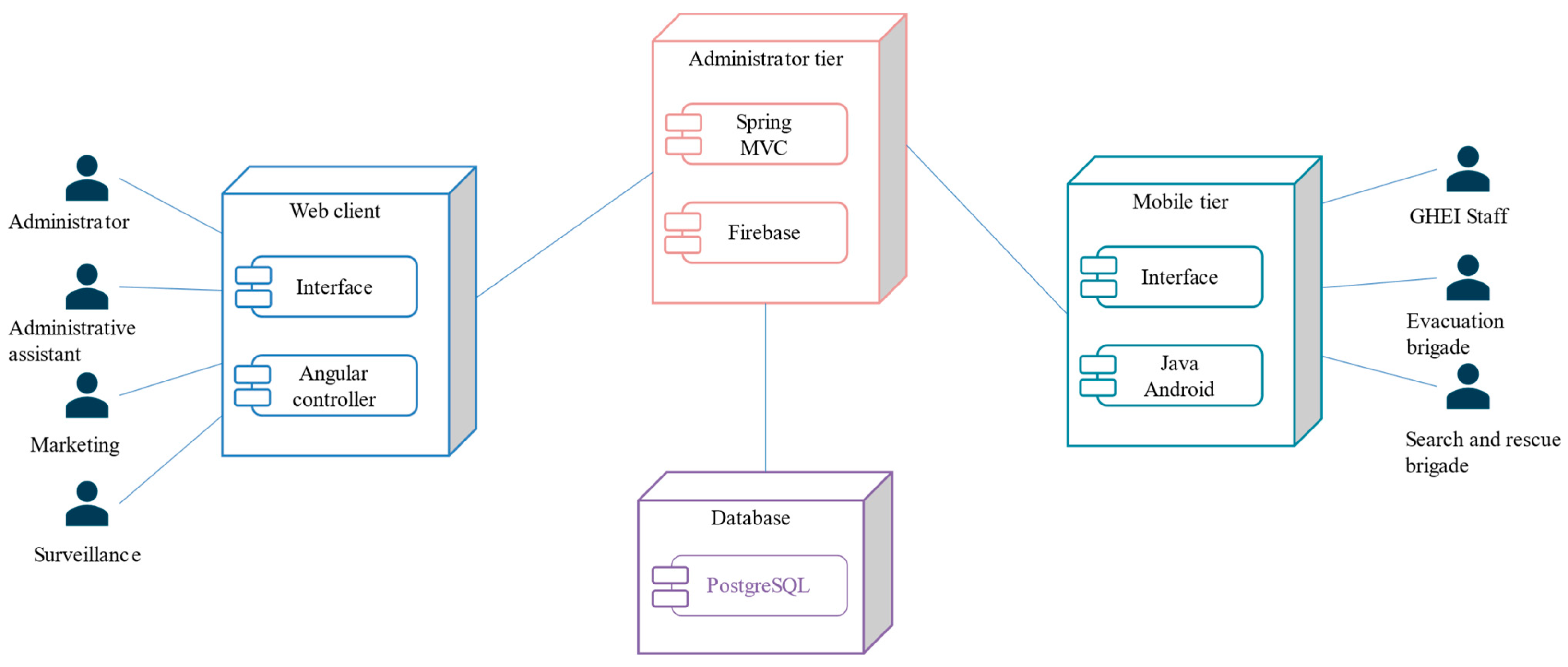
2.2.3. Deployment View

Figure 4 shows the deployment diagram of the proposed software architecture in this work. The nodes that integrate the deployment diagram are described below:
  • Web client: This node contains components to manage the information of people, buildings, institutions, networks, and reports. It communicates with the administrator tier to save or consult such information.
  • Administrator tier: This node manages the information requested or sent through REST requests from the web client and the mobile tier.
  • Mobile tier: This node contains the components to execute the mobile application. This node displays the location information of the people, as well as personal information, a directory, and manuals, among others. The mobile tier communicates directly with the administrator tier through REST requests.
  • Database: Its main function is to manage the information sent from the administrator tier.

2.3. Software Architecture Instantiation

In this work, a system oriented to managing evacuation, search, and rescue brigade and victim activities before, during, and after an earthquake was developed based on the proposed architecture. This system includes the two tiers proposed in the software architecture. The implemented services in the manager tier are aimed at four types of users:
  • Administrator: This manages the people registered in the system, internal, external, and visitors; information on the institution’s buildings; general data on the institution; information on Wi-Fi networks; and generates reports.
  • Administrative assistant: This user manages the information of internal and external people in the system.
  • Marketing: This manages the information of the visitors on the system.
  • Surveillance: This user disposes of the list of people in the system and can check the attendance per day; besides, this user can also mark the entry or intermittent exit time and capture the final departure time. This user has the option of generating a report of the people who are in the GHEIs.
On the other hand, the services that were implemented in the mobile tier are aimed at three types of users:
  • GHEI Staff (Victims): GHEI students, administrative staff, and academic staff.
  • Evacuation Brigade Leader: Refers to the person assigned as the evacuation brigade leader.
  • Search and Rescue Brigade Leader: The person assigned as the head of the search and rescue brigade.
  • The main services for the mobile tier called AlertGHEI are described below.

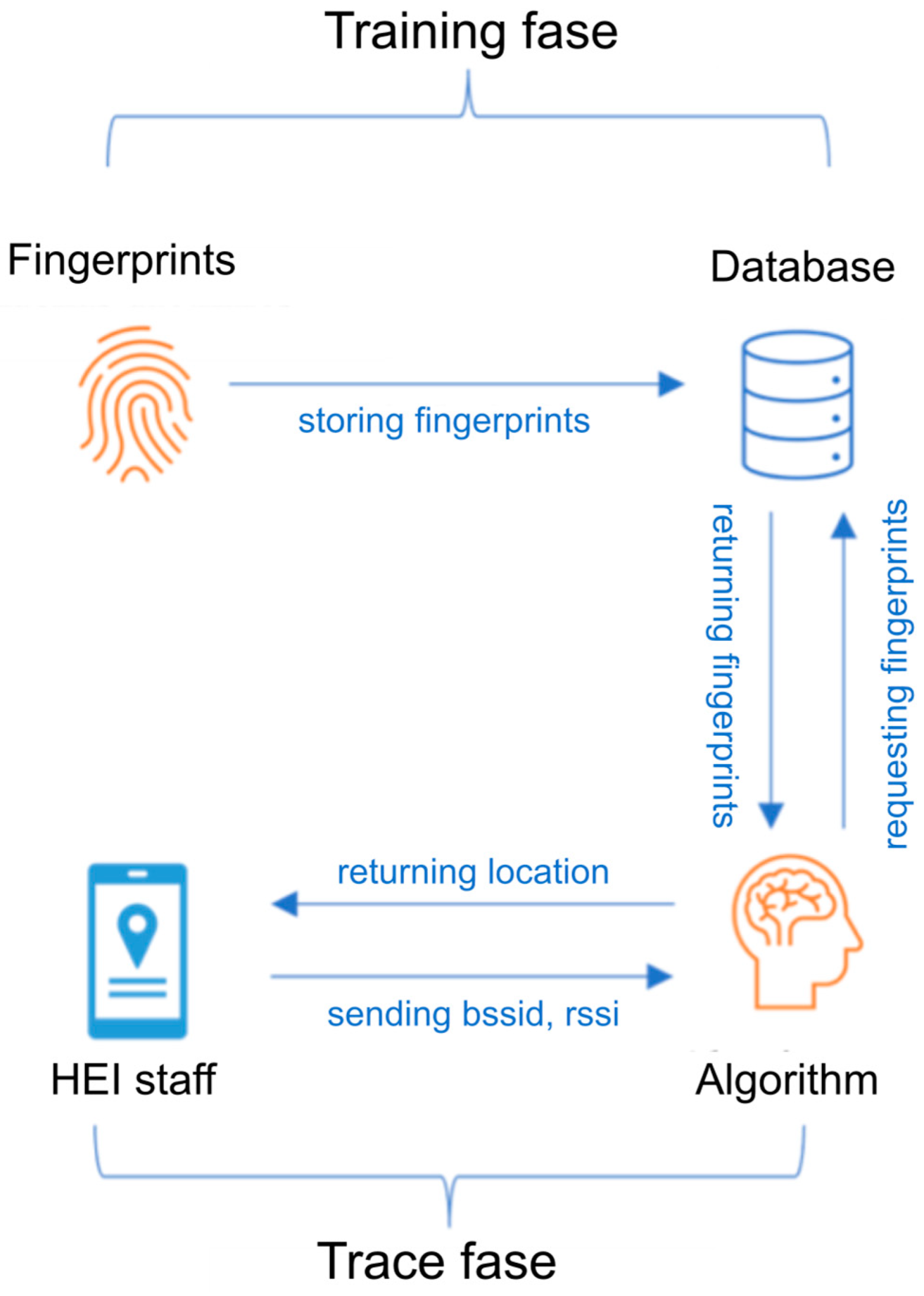
2.3.1. Indoor People Location Service

One of the main problems faced by the search and rescue brigade is determining whether people are inside the campus facilities and buildings after an earthquake. Therefore, the indoor people location service was proposed to support this activity. This service receives as input the signal intensity of the access points detected by the person’s mobile device and returns the person’s location within a specific building and floor. Because users’ mobile devices can receive multiple RSSIs, this problem can be addressed as a classification problem. The development of the indoor location service involved implementing the fingerprint method (see Figure 5).
The aim of the fingerprinting method is to obtain the RSSI of WLAN access points (APs) or reference points (RPs) at each point of interest and map it to a fingerprint database. The fingerprinting procedure is divided into two phases: The training phase (offline) and the trace phase (online).
  • Training phase: During this phase, the RSSI of each place of interest is taken as a fingerprint and stored in a database.
  • Trace phase: This phase uses a classification algorithm to match the data that the application user is sending with what is found in the database, such as fingerprints.
The database of this project has a table called Network, where all the Wi-Fi networks that the GHEIs have are registered—the important information that is saved is the network identifier (SSID) and the primary identifier of the service set (BSSID). This information is consulted by the user and saved in its database in order only to select those networks that belong to the GHEI. During the training phase, the fingerprints of each AP that arrives at an RP are mapped and stored in the database through the web application that has the fingerprint module. When a fingerprint is added, modified, or deleted, an ARFF (Attribute-Relation File Format) file is created since it is the default format for the WEKA library (Waikato Environment for Knowledge Analysis) [40], which is a software platform for machine learning and data mining developed in Java and licensed under the GNU-GPL license.
WEKA was selected because it provides a comprehensive set of machine learning algorithms that represent the state-of-the-art in the field. Additionally, it allows the fine-tuning of hyperparameters and facilitates experimentation, which is not commonly explored in similar studies. Although WEKA can work with several types of files, the ARFF is specific to the library, and therefore, WEKA works better with this type of file. These files are plain text and can be edited in any text editor, but they must follow a particular structure, and there are two parts: the header and the data. The ARFF is created with the information from the fingerprints. On the other hand, during the trace phase, the users through the mobile application send the id of the network table that they detect with the greatest intensity and its RSSI to the REST API; for this procedure, there exists, within the application, the pre-processing class in charge to filter the list of networks that only belong to the GHEIs, and that the signal strength is greater than −95 db. That class returns an ordered list of networks, and the application selects the network with the highest intensity. When the information reaches the REST API, the ARFF created with the fingerprints is used to train the classification algorithms. To select an appropriate machine learning algorithm, we considered the nature and size of the dataset. Since our dataset consisted of 7050 fingerprint instances, it was not large enough to justify the use of more complex models such as deep learning. Instead, we opted for the K-nearest neighbor (KNN) and J48 decision tree, as both are well-suited for moderate-sized datasets and provide interpretable results. The characteristics of the data were: (i) ssid: This is a string value and defines the SSID of the networks in the database; (ii) bssid: this is an integer value corresponding to the network’s ID in the database table; (iii) rssi: this is an integer value and is the received signal strength mapped as a fingerprint. Consequently, the target was the departments’ identifiers (IDs), where the fingerprints were mapped, with 36 in total. The results were compared using the accuracy metric of the models generated with J48 and KNN using 10-fold cross-validation. However, no significant differences were found on average, with 86% and 85% accuracy, respectively. Given the computational complexity of KNN, which scales linearly with the dataset size O(nd), where n is the number of instances and d is the number of dimensions, its performance could degrade with larger datasets due to increased resource consumption and response time. In contrast, J48, which generates a rule-based model during training, has an inference complexity of O(h), where h is the tree height, making it more scalable and efficient for real-time applications. Therefore, we selected the model generated with J48 as the classifier of the fingerprint method, not only because its classification accuracy was slightly higher but also due to its superior scalability and efficiency in handling larger datasets. Furthermore, a tree model is an if-then type structure where the criteria do not involve operations with the data, so it is not sensitive to aspects such as the distribution or data types. Regarding the trace phase, when the algorithm identifies the location, it is returned to the user and shown in the application’s main graphical user interface (see Figure 6). The process of requesting the user’s location is carried out every 15 min and is saved in the database.

2.3.2. Emergency Reports

This service was developed for GHEI personnel users. When a user logs into the application, they can select the type of emergency they want to report and have 10 s to cancel the report. The emergency report takes the user’s location and the selected emergency type (medical, gas leak, water leak, fire) (see Figure 7), and this information is sent to the database.

2.3.3. People’s Location Inside the Building

Brigade leaders can see the people located inside a specific building and floor. This function helps brigades ensure that no one remains inside the buildings once the evacuation is completed (see Figure 8a). In cases where people lose connection to WLAN access points or reference points (RPs) due to damage to the building’s network infrastructure caused by the earthquake, the system reports to the brigade leaders the last location of the people inside the building stored in the DB, along with the timestamp when it was recorded. We note that the system automatically configures the indoor location of people service for every specific time range (for example, every 5, 10, or 15 min). On the other hand, we are working on extending the system to activate the location retrieval service automatically for all individuals in a building when a seismic alert is triggered or received.

2.3.4. Roll Call Service of People Who Are Inside a GHEI

This service provides a list of people present within an entire GHEI. This list is used to conduct a roll call within the security zones; it can classify people as located and save that information (see Figure 8b). It also provides detailed information when the user clicks on a specific person’s name. We present the Spanish user interfaces of the developed system for two reasons: the Mexican context in which this work is framed, and the preliminary usability evaluation of the system was conducted with the Spanish user interfaces. However, depending on the language settings of the Android device, the interfaces are presented in Spanish or English to the user. To achieve this, we have included a file called strings.xml in the res/values-en folder of our Android Studio project. This file automatically provides English text strings to the user when the Android device’s language is set to English.

2.4. Software Architecture Evaluation

Our architecture was evaluated using four approaches. The first approach assesses the critical design of the proposed software architecture. In this approach, we verify the correctness and coverage of the requirements to verify that the proposed software architectural design addresses the desired requirements. The second approach assesses the product quality resulting from our software architecture in terms of functional suitability [41]. The third approach assesses the usability of the prototype developed following the proposed software architecture. Finally, the fourth approach assesses the proposed software architecture using the RAModel model.

2.4.1. Critical Evaluation of Proposed Software Architecture Design

The verification of the desirable requirements (described in Section 2.1) for the design of the proposed software architecture is described in this section. The requirements considered in the design of the proposed software architecture in this work are described below according to the proposed layers. The storage, communication, and presentation layers were designed to consider requirements REQ1-REQ9. In the plugin, sensorization, storage, information gathering, emergency actions, communication, and presentation layers, requirements REQ10, REQ13, and REQ28 were mapped. The storage, information gathering, emergency actions, reports, communication, and presentation layers were created to address REQ11, REQ12, REQ14, REQ18, REQ20, REQ21, REQ22, REQ23, REQ24, REQ29, REQ30, and REQ36. Requirements REQ15, REQ16, REQ17, REQ19, REQ25, REQ26, and REQ27 were mapped in the plugin, sensorization, storage, information gathering, communication, and presentation layers. The plugin, sensorization, storage, and communication layers were designed to consider REQ31, REQ32, REQ34, and REQ37. The proposed software architecture is based on tiers, layers, and architectural patterns such as MVC and MVVM to meet the requirements REQ33, REQ34, REQ35, REQ36, REQ37, and REQ38. In our software architecture, tiers complement layers; services are modeled in vertical abstract layers, while the tiers handle the functionality of a specific layer within the nodes. Each layer is independent since it performs a specific service. The mobile tier is designed to operate on devices with limited storage and processing capabilities (for example, mobile devices). On the other hand, the manager/administrator tier is designed to work on devices with greater storage and processing capacity, such as servers. Therefore, the workload is higher in the administrator tier than in the mobile tier. Although both tiers contain layers with the same names, their services depend on the device’s resources. Based on the obtained results, it is concluded that the proposed software architecture in this work addresses all the desirable requirements for the development of smart mobile distributed systems that are focused on managing the activities of people and members during earthquakes at GHEIs. In this work, we also show that it is possible to develop an SMDS focused on managing the activities of people and members of the brigades during earthquakes based on the proposed software architecture design with different architectural views (conceptual, component, and deployment views). Developers and research groups building upon our software architecture will be able to develop SMDS solutions focused on managing emergency cases while ensuring the required quality attributes and specifications.

2.4.2. Functional Suitability

In this approach, functional suitability tests were performed using simulated scenarios. To evaluate the developed system for functional suitability, unit and integration tests were carried out to develop system services considering simulated earthquake scenarios. The simulated earthquake scenarios used in the unit and integration tests were based on the earthquake drills description outlined in the Mexican Civil Protection Program and school civil protection programs [5,6,7,8], which detail the actions to be carried out before, during, and after an earthquake. In general, the scenarios included three two-floor buildings, two safety zones, two alarms, and the four brigades proposed in the civil protection program (evacuation, search and rescue, first aid and prevention, and fire extinguishing). Each brigade included two members: the brigade leader and an alternate. Each building was simulated to have 10 to 15 occupants. During scenario development, it was assumed that two to three individuals would remain inside the buildings, and the other participants would move to the safety zones. In the security zones, the brigade leaders conducted a roll call of people, marking individuals as located or absent from their applications. Subsequently, the head of the search and rescue brigade, using the developed system’s services, identified the location of the people who remained inside the buildings to assist with the corresponding evacuation. Additionally, in one building, a participant simulated reporting a fire emergency. As a result, the brigade leader received an emergency report containing the name of the individual reporting, the type of emergency, and the location where the emergency was occurring. Finally, brigade leaders were instructed to compile a comprehensive report on the simulated earthquake drill for submission to the civil protection authorities.
In the case of the mobile tier, it was deployed on three mobile devices. Concerning the manager tier, it was executed on a laptop. Table 1 describes the characteristics of these devices.
The execution of the tests followed the standard format composed of the following elements:
  • Module: Name of the module to test.
  • Test: Test identifier.
  • Goal: Indicates the purpose of performing the test.
  • Requirements: Conditions that must be listed to execute the module.
  • Sequence: Indicates the steps that must be performed to achieve operation.
  • Achieved: Indicates if the correct operation is achieved or not.
  • Result: Indicates the results obtained.
The purpose of applying unit tests is to ensure that the services or modules produce the expected results. Table 2 shows the general report of the unit tests conducted on the services of the manager tier modules, considering the administrator and assistant administrator users. Errors detected in the executed unit tests were fixed.
On the other hand, Table 3 shows the final report of the unit tests conducted on the services of mobile tier modules for the GHEI personnel, evacuation brigade leader, and search and rescue brigade leader users. Errors detected in the executed unit tests were fixed.
The integration tests performed on both tiers validate the system’s behavior as a whole and ensure that its functionality and generated results are correct. The results of the integration tests are summarized in Table 4.
As a result of the unit and integration tests, a fully functional system was developed, designed to manage evacuation and search and rescue brigade activities before, during, and after an earthquake.

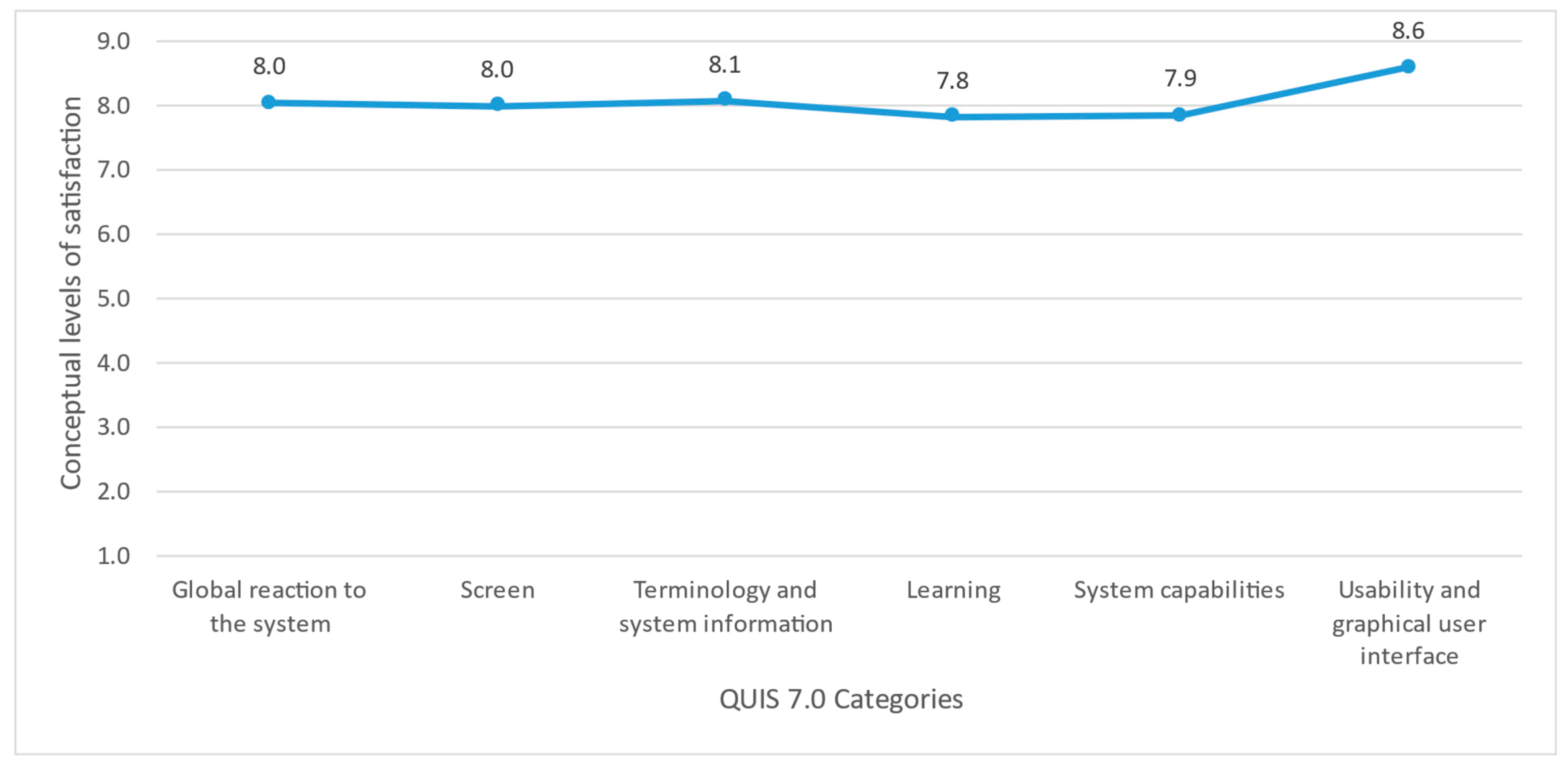
2.4.3. Usability Assessment of the Prototype Developed Based on the Proposed Software Architecture

We conducted a usability assessment of an SMDS prototype developed based on the proposed software architecture in this work, applying a laboratory study [42] with four users: one GHEI student, one academic staff member, one evacuation brigade leader, and one search and rescue brigade leader, to validate the considered requirements in our proposed software architecture. Table 5 describes the characteristics of the usability assessment participants. Notably, the users participating in this usability evaluation had received continuous training in civil protection programs that detail the actions that must be carried out before, during, and after an earthquake.
Following the guidelines of the ISO/IEC 25019:2023 usability standard [43], user satisfaction was assessed using the QUIS 7.0 questionnaire [44,45]. This questionnaire consists of a set of questions grouped into aspects such as a (a) general reaction to the software, (b) system user interface (screens), (c) terminology and system information, (d) learning, (e) system capabilities, and (f) usability and graphical user interface. In this instrument, the Likert scale, selected for each question, consists of nine conceptual satisfaction levels, where 1 point is the lowest rating, and 9 points represent the highest rating. Once the user’s answers are compiled, the average of each category is estimated, as well as the total average. Based on [44,45,46], the acceptability ranges are as follows:
  • 1 ≤ satisfaction ≤ 3: unsatisfactory
  • 4 ≤ satisfaction ≤ 6: acceptable
  • 7 ≤ satisfaction ≤ 9: satisfactory
The average results of each category, based on the responses of the QUIS 7.0 satisfaction questionnaire of the users, are presented in Table 6.
Based on these results, the final average was computed to measure the user’s satisfaction levels. The averages of each category were added and then divided by six, which is the total number of categories. The final average satisfaction score was 8.1. Therefore, the satisfaction aspect since the users’ point of view is satisfactory in terms of a global reaction to the system (utility, flexibility, ease of use, among other features), screen, terminology, information system (user support to reach his/her goal, consistency in the location and content of messages), learning (user facility to learn how to use the system), system capacities, and usability and graphical user interface (design of the software interface); see Figure 9.

2.4.4. Evaluation of the Proposed Software Architecture Based on the RAModel

The elements and their relationships that a reference software architecture must meet are described in the RAModel model proposed by Nakagawa [26]. RAModel defines four categories of elements: domain, application, infrastructure, and cross-cutting elements. The domain category refers to related aspects of legislation, standards, quality attributes, and system compliance. The application category refers to compliance with functional requirements, objectives, needs, limitations, scopes, and risks of the software architecture. The infrastructure category addresses the elements related to the development of software systems based on the instantiation of the reference software architecture. Finally, the cross-cutting element category considers aspects related to the domain, applications, and infrastructure categories in terms of domain terminology and external and internal communication. In this work, we used the element groups proposed in [26] to evaluate the proposed software architecture based on the RAModel model. The evaluation results are presented below. Regarding the domain category elements, the proposed software architecture is based on the official documentation of the Mexican civil protection program and standards to ensure the security of the personal data of the system users, and the quality attributes considered are defined. Therefore, all the elements of the domain group are considered in the design of the reference software architecture proposed in this work. As for the elements of the application category, the identified requirements have been considered in the design of the software architecture proposed in this work. The objectives, limitations, and scopes for the proposed software architecture were defined in detail. The potential risk identified is the location accuracy provided by the methods used in the indoor person location service. Regarding the elements of the infrastructure category, the proposed software architecture was designed and developed based on best practices. The conceptual, component, and deployment architectural views of the proposed software architecture are described in detail. In the component and instantiation diagrams of the software architecture, the software and hardware elements are described in detail. Finally, in the cross-cutting elements category, the domain terminology has been included, and the communication between the different layers, tiers, modules, and components of the proposed software architecture is described. Based on the evaluation results, the proposed software architecture meets the necessary elements of a reference software architecture according to the RAModel reference model.

3. Related Work

Several studies [11,12,13,14,15,16,17,18,19,20,21,22,23,24,25] propose smart mobile distributed systems for emergency management, focusing on supporting activities for victims and rescue brigades before, during, and after earthquakes. We analyzed these systems in terms of their services, indoor location methods, and architectural styles to assess their requirements, correctness, and coverage in the emergency management domain. A critical priority for rescue brigades is locating individuals in unsafe areas after an earthquake, making indoor people’s location a key service. In this regard, we identified the strengths and limitations of the methods used in these systems. Software architecture aims to reduce complexity through abstraction and best practices, offering benefits like standardization, reusability, and quality improvement. Further below, we present these systems’ architectural styles, views, and patterns, with some comprehensive findings.

3.1. Main Services of the Proposed Systems

The analyzed systems primarily target three user groups: victims, rescuers (or first responders), and administrators, who are typically assumed to have basic to intermediate digital skills. The core functionality of these systems is indoor location tracking. Works such as [11,12,13,14,15,16,17,18,19,20,21,23,24,25] determine victim locations via mobile applications and display them on building plans accessible to rescuers. Additionally, systems in [13,15,16,18,25] provide victims with routes to the nearest exits. In [13,18], victims can request assistance from rescuers during emergencies. The system in [18] also offers illustrated or audio-based guides to address personal emergencies or assist others, covering scenarios like heart attacks, bleeding, difficulty breathing, and fractures. The work in [11] introduces a context-aware victim assessment system using mobile sensors, questionnaires, and passive monitoring. From the analysis of these systems [11,12,13,14,15,16,17,18,19,20,21,22,23,24,25], the main services identified include recording RSSI data for Wi-Fi and Bluetooth networks (for fingerprinting), indoor location tracking, guiding victims to exits, assessing health statuses, generating emergency reports, and enabling help requests. However, none of these systems comprehensively address the full spectrum of the requirements outlined by civil protection programs for earthquake scenarios [5,6,7,8].

3.2. Methods Used in the Indoor People Location Service

The analyzed systems leverage the received signal strength indicator (RSSI) from Wi-Fi networks or Bluetooth beacons, which transmit low-energy signals to nearby mobile devices without prior synchronization. Studies [11,12,16,18,22,24] store Wi-Fi RSSI data in a database along with the basic service set identifier (BSSID) and the point of interest where the signal was captured, a technique known as fingerprinting. For location determination, [11,18,21,24] apply classification algorithms such as K-nearest neighbors (KNN) or naïve Bayes. Systems using beacon-based RSSI include [13,14,15,17,19,25]. Notably, ref. [21] combines Wi-Fi and beacon signals to ensure location tracking even when one signal type is unavailable. The hybrid approach in [17] integrates PDR navigation with real-time beacon RSSI analysis. These systems rely on RSSI fingerprinting for user localization through Wi-Fi access points or Bluetooth beacons. However, while some studies measure only three fingerprints per meter, tests suggest capturing approximately ten RSSI readings per point of interest to enhance location accuracy for victims within a building.

3.3. Architectural Views and Patterns of the Proposed Systems

The analyzed works [11,12,13,14,15,16,17,18,19,20,21,22,23,24,25] outline system architectures for emergencies using (1) physical views such as N-Tier, client-server, and cloud computing styles; (2) implementation views like component-based and layered architectures; and (3) communication/process views based on service-oriented architectures, including REST. Specifically, 60% adopt a client-server architecture [11,12,13,16,18,21,22,23,24], 14% use SOA [14,19], 13% implement N-Tier [15,17], and 13% employ layered architectures [20,25]. However, none provide a comprehensive architecture to standardize development, leading to issues such as a lack of consistency and limited quality in addressing requirements for victims and rescue brigades before, during, and after earthquakes, as outlined in civil protection programs [5,6,7,8].

4. Verification and Comparison of Desirable Requirements Considered in Related Work and Our Work

This section verifies and compares the desirable requirements considered in software architectures aimed at developing SMDS focused on managing ECs reported in related work [11,12,13,14,15,16,17,18,19,20,21,22,23,24,25] and our work. The requirement verification is based on identifying desirable requirements that the systems oriented to managing the activities of the victims and evacuation, search, and rescue brigades must carry out before, during, and after an earthquake (see Section 2.1). Based on the requirement verification results obtained, one related work can be classified within the prevention subprogram of civil protection since it included a functional requirement to show the protocols when personal emergencies occur, i.e., it shows a first aid manual according to the situation [18]. Regarding the aid subprogram, five works consider functional requirements that are oriented toward the activities of this subprogram, such as showing the route to the nearest exit depending on the user’s location, real-time consultation of risk areas, and modifying the indications of the nearest exits [13,15,16,18,25]. Concerning the recovery subprogram, after the emergency, it is notable that all the systems consider the functional requirements that are focused on the activities of this subprogram [11,12,13,14,15,16,17,18,19,20,21,22,23,24,25]. We note that none of the related works [11,12,13,14,15,16,17,18,19,20,21,22,23,24,25] propose a reference software architecture that includes all the desirable requirements that a system must consider for emergencies such as earthquakes. In particular, the requirements that are not considered in the software architectures proposed are the following: RF17—See list of academic staff, students, and outsiders, RF18—See details of the selected person, RF20—Classify building departments, RF22—Closing off evacuated areas and RF23—View report on closed areas.
The lack of attention to the desirable requirements in the proposed works has led to suboptimal design decisions. Suboptimal design decisions in software architectures generate SMDSs focused on managing emergency cases that are not standardized in terms of the services provided to users, types and formats of data, and the use of incompatible protocols for exchanging, processing, and storing the information obtained. This implies a fragmentation of the developed systems and affects the functional suitability, usability, and interoperability of the proposed systems, as well as other types of systems needed in case of earthquakes in health and security. Specifically, imprecise architectural design has led to a lack of standardization and low quality of SMDSs focused on managing ECs regarding requirement coverage and correctness. Therefore, these works [11,12,13,14,15,16,17,18,19,20,21,22,23,24,25] do not adequately implement the activities that victims and evacuation, search, and rescue brigades must carry out in case of earthquakes in the proposed systems. Our work is characterized by modeling all the desirable requirements that a software architecture focused on developing systems oriented to managing the activities of the victims and evacuation, search, and rescue brigades must carry out before, during, and after an earthquake at GHEI. Based on the results obtained, our software architecture provides adequate architectural support for developing smart mobile distributed systems oriented to manage emergency cases at GHEIs with the required requirements and quality attributes.

5. Conclusions and Future Work

This work presented a layered reference software architecture for developing smart mobile distributed systems (SMDSs) to manage emergency cases such as earthquakes at GHEIs. Our software architecture was designed based on the functional and non-functional requirements derived from each prevention, relief, and recovery subprogram defined in the Mexican National Civil Protection Program, as well as the analysis of the services described in the related works. The layers that integrate our software architecture are plugin, sensorization, storage, information gathering, communication, reports, emergency actions, and presentation. In our case, we considered two tiers: mobile and administrator. The tiers complement layers; services are modeled in vertical abstract layers, while the tiers deal with the functionality of a specific layer in the nodes. Each layer is independent since it performs specific services. The mobile tier was developed on devices with limited processing and storage features. On the other hand, the manager tier was designed to run on devices with higher processing and storage capacity. Therefore, the workload is higher in the admin than in the mobile tier. The evaluation of our architecture was carried out based on four approaches. The first approach assesses the requirements for correctness and coverage. Based on the results obtained, it is concluded that the proposed software architecture in this work addresses all the desirable requirements for the development of SMDSs, which is focused on managing the activities of people and members of the brigades in case of earthquakes at GHEIs. The second evaluation approach assessed the product quality resulting from our software architecture regarding functional suitability. The results of the tests that were carried out considering simulated scenarios show that the developed system based on our architecture meets the quality attributes of functional suitability. The third approach assesses the usability of a developed prototype based on the proposed reference software architecture in this work applying a laboratory study. The usability results from the users’ perspective showed satisfactory usability. The fourth approach assessed our software architecture by applying the RAModel model. In this case, the results show that our software architecture proposal considers all the main elements described by the RAModel for reference architectures. Additionally, we compared and verified the desirable requirements addressed in related works with those covered by our software architecture. The results show that our work is characterized by modeling all the desirable requirements for managing and streamlining the activities of the victims and evacuation, search, and rescue brigades before, during, and after an earthquake. Therefore, our reference software architecture is characterized by providing suitable architectural support for developing SMDSs oriented to managing ECs at GHEIs with the required requirements and quality attributes. From our point of view, the most important advantages of our reference software architecture are as follows: (a) defining the basic technical guidelines that an SMDS oriented to managing an EC at a GHEI must possess, (b) streamlining the overall development by providing a solid and standardized framework to developers, and (c) contributing to meeting the required requirements arising from the specific domain of SMDSs oriented to managing ECs at GHEIs. As future work, we will consider implementing other classification algorithms within the indoor location service to evaluate and improve the accuracy of the location of people and the conduct of a usability evaluation of the system developed based on the proposed architecture with the participation of at least 20 users (five participants for each type of user) in official earthquake drills.

Author Contributions

Conceptualization, L.Y.C.R., E.L.D. and Y.H.V.; methodology, L.Y.C.R., E.L.D., Y.H.V. and S.D.I.; software, L.Y.C.R., E.L.D., Y.H.V. and S.D.I.; validation, L.Y.C.R., E.L.D., Y.H.V., S.D.I., M.A.M.N. and J.D.L.C.; formal analysis, L.Y.C.R., E.L.D., Y.H.V., S.D.I., M.A.M.N. and J.D.L.C.; investigation, L.Y.C.R., E.L.D., Y.H.V., S.D.I., M.A.M.N. and J.D.L.C.; resources, L.Y.C.R., E.L.D. and Y.H.V.; data curation, L.Y.C.R., E.L.D., Y.H.V., S.D.I., J.D.L.C. and M.A.M.N.; writing—original draft preparation, L.Y.C.R., E.L.D., Y.H.V., S.D.I., M.A.M.N. and J.D.L.C.; writing—review and editing, L.Y.C.R., E.L.D., Y.H.V., S.D.I., M.A.M.N. and J.D.L.C.; visualization, L.Y.C.R., E.L.D., Y.H.V., S.D.I., M.A.M.N. and J.D.L.C.; supervision, L.Y.C.R., E.L.D., Y.H.V. and S.D.I.; project administration, L.Y.C.R., E.L.D. and Y.H.V.; funding acquisition, L.Y.C.R., E.L.D., Y.H.V., S.D.I., M.A.M.N. and J.D.L.C. All authors have read and agreed to the published version of the manuscript.

Funding

This research received no external funding, and The APC was funded by Centro de Investigación y de Estudios Avanzados del Instituto Politécnico Nacional.

Institutional Review Board Statement

Not applicable.

Informed Consent Statement

Not applicable.

Data Availability Statement

Data are contained within the article. Further inquiries can be directed to the corresponding author.

Conflicts of Interest

The authors declare no conflicts of interest.

References

  1. Servicio Sismológico Nacional. Zona de Subducción Mexicana y su Potencial Para un Sismo Mayor. Available online: http://www.ssn.unam.mx/jsp/reportesEspeciales/sismoMayor.pdf (accessed on 27 October 2023).
  2. Earthquake Hazards. The Science of Earthquakes. Available online: https://www.usgs.gov/natural-hazards/earthquake-hazards/science/science-earthquakes?qt-science_center_objects=0#qt-science_center_objects (accessed on 12 October 2023).
  3. Servicio Geológico Mexicano. SISMOS: Causas, Características e Impactos. 2017. Available online: https://www.gob.mx/sgm/es/articulos/sismos-causas-caracteristicas-e-impactos?idiom=es (accessed on 12 October 2023).
  4. Servicio Sismológico Nacional. Estadísticas de los Sismos Reportados por el SSN. Available online: http://www2.ssn.unam.mx:8080/estadisticas/ (accessed on 12 October 2023).
  5. Secretaría de Educación Pública. Guía Para Elaborar o Actualizar el Programa Escolar de Protección Civil. 2018. Available online: https://educacionbasica.sep.gob.mx/multimedia/RSC/BASICA/Documento/201808/201808-RSC-cYNgcsRRbr-proteccionC2018.pdf (accessed on 12 October 2023).
  6. Secretaría de Educación Veracruzana. Programa Interno de Protección Civil. 2019. Available online: https://www.sev.gob.mx/proteccion-civil/files/2019/04/PROGRAMA_INTERNO-PC.pdf (accessed on 12 October 2023).
  7. Gobierno del Estado de Colima. Plan de Protección Civil y Emergencia Escolar. 2020. Available online: http://descargas.secolima.gob.mx/secolima/seguridadyemergencia/2020/1A-%20Plan%20por%20escuela.pdf (accessed on 12 October 2023).
  8. De Diputados, D.; Congreso, D.; Unión, L. Ley General De Protección Civil. 2014. Available online: https://www.ucol.mx/content/cms/13/file/federal/LEY_GRAL_DE_PROT_CIVIL.pdf (accessed on 12 October 2023).
  9. Martínez, B. Las TIC como Herramienta en las Situaciones de Emergencia. 2007. Available online: https://upcommons.upc.edu/bitstream/handle/2099/4479/06_TIC_y_Emergencias_cast.pdf?sequence=1&isAllowed=y (accessed on 14 October 2023).
  10. Instituto Federal de Telecomunicaciones. En México hay 80.6 Millones de Usuarios de Internet y 86.5 Millones de Usuarios de Teléfonos Celulares: ENDUTIH. 2019. Available online: https://www.inegi.org.mx/contenidos/saladeprensa/boletines/2019/OtrTemEcon/ENDUTIH_2018.pdf (accessed on 14 October 2023).
  11. Yoon, H.; Shiftehfar, R.; Cho, S.; Spencer, B.F.; Nelson, M.E.; Agha, G. Victim Localization and Assessment System for Emergency Responders. J. Comput. Civ. Eng. 2016, 30, 04015011. [Google Scholar] [CrossRef]
  12. Mutiawani, V.; Nazila, C.T.; Saputra, K.; Mabrina, A. Design of an Indoor Localization System based on WLAN for Assisting Victim’s Evacuation Process. In Proceedings of the 2nd International Conference on Applied Information Technology and Innovation, Denpasar, Indonesia, 21–22 September 2019; pp. 6–10. [Google Scholar] [CrossRef]
  13. Depari, A.; Flammini, A.; Fogli, D.; Magrino, P. Indoor Localization for Evacuation Management in Emergency Scenarios. In Proceedings of the Workshop on Metrology for Industry 4.0 and IoT, Brescia, Italy, 16–18 April 2018; pp. 146–150. [Google Scholar] [CrossRef]
  14. Li, C.C.; Su, J.; Chu, E.T.H.; Liu, J.W.S. Building/Environment Data/Information Enabled Location Specificity and Indoor Positioning. IEEE Internet Things J. 2017, 4, 2116–2128. [Google Scholar] [CrossRef]
  15. Rodriguez-Sanchez, M.C.; Fernández-Jiménez, L.; Jiménez, A.R.; Vaquero, J.; Borromeo, S.; Lázaro-Galilea, J.L. “HelpResponder—System for the Security of First Responder Interventions. Sensors 2021, 21, 2614. [Google Scholar] [CrossRef] [PubMed]
  16. Facchinetti, D.; Psaila, G.; Scandurra, P. Mobile cloud computing for indoor emergency response: The IPSOS assistant case study. J. Reliab. Intell. Environ. 2019, 5, 173–191. [Google Scholar] [CrossRef]
  17. Ciabattoni, L.; Foresi, G.; Monteriù, A.; Pepa, L.; Pagnotta, D.P.; Spalazzi, L.; Verdini, F. Real time indoor localization integrating a model based pedestrian dead reckoning on smartphone and BLE beacons. J. Ambient. Intell. Humaniz. Comput. 2019, 10, 1–12. [Google Scholar] [CrossRef]
  18. Ghazal, M.; Ali, S.; Al-Halabi, M.; Ali, N.; Khalil, Y.A. Smart Mobile-Based Emergency Management and Notification System. In Proceedings of the IEEE 4th International Conference on Future Internet of Things and Cloud Workshops, Vienna, Austria, 22–24 August 2016; pp. 282–287. [Google Scholar] [CrossRef]
  19. Liu, J.W.S.; Lin, F.T.; Chu, E.T.H.; Zhong, J.L. Intelligent indoor emergency evacuation systems: Reference architecture and data requirements. In Proceedings of the Future Technologies Conference, San Francisco, CA, USA, 6–7 December 2016; pp. 600–609. [Google Scholar] [CrossRef]
  20. Poy, M.; Duffy, B.A. Cloud-Enabled Building and Fire Emergency Evacuation Application. IEEE Cloud Comput. 2014, 1, 40–49. [Google Scholar] [CrossRef]
  21. Biehl, J.T.; Cooper, M.; Filby, G.; Kratz, S. LoCo: A Ready-to-Deploy Framework for Efficient Room Localization Using Wi-Fi. In Proceedings of the ACM International Joint Conference on Pervasive and Ubiquitous Computing, Seattle, WA, USA, 13–17 September 2014; pp. 183–187. [Google Scholar] [CrossRef]
  22. Son, D.; Cho, E.; Choi, M.; Khine, K.; Kwon, T. Effects of Partial Infrastructure on Indoor Positioning for Emergency Rescue Evacuation Support System. In Proceedings of the First CoNEXT Workshop on ICT Tools for Emergency Networks and DisastEr Relief, Incheon, Republic of Korea, 11–12 December 2017; pp. 13–17. [Google Scholar] [CrossRef]
  23. Atiq, F.F.M.; Bandung, Y. Viloc: An Android Mobile App Used for Indoor-Trapped Victim Location Visualization. In Proceedings of the International Conference on ICT for Smart Society, Bandung, Indonesia, 2–4 August 2021; pp. 1–7. [Google Scholar] [CrossRef]
  24. Mutiawani, V.; Nazila, C.T.; Saputra, K. WLAN Based Indoor Localization System for Evacuation of Victims in a Building. In Proceedings of the International Conference on Electrical Engineering and Informatics, Aceh, Indonesia, 27–28 October 2020; pp. 1–6. [Google Scholar] [CrossRef]
  25. Zualkernan, A.; Aloul, F.A.; Sakkia, V.; Noman, H.A.; Sowdagar, S.; Hammadi, O.A. An IoT-based Emergency Evacuation System. In Proceedings of the IEEE International Conference on Internet of Things and Intelligence System, Bali, Indonesia, 5–7 November 2019; pp. 62–66. [Google Scholar] [CrossRef]
  26. Nakagawa, E.; Oquendo, F.; Becker, M. RAModel: A Reference Model for Reference Architectures. In Proceedings of the 2012 Joint Working IEEE/IFIP Conference on Software Architecture and European Conference on Software Architecture, Helsinki, Finland, 20–24 August 2012; IEEE Press: New York, NY, USA, 2012; pp. 297–301. [Google Scholar] [CrossRef]
  27. Johannesson, P.; Perjons, E. An Introduction to Design Science; Springer: Cham, Switzerland, 2014. [Google Scholar]
  28. Rivas, L.Y.C.; Domínguez, E.L.; Velázquez, Y.H.; Isidro, S.D.; Nieto, M.A.M.; De La Calleja, J. Intelligent Mobile Distributed Management Systems for Emergencies Such as Earthquakes or Fires: A Systematic Literature Review. In New Perspectives in Software Engineering. Studies in Computational Intelligence; Mejía, J., Muñoz, M., Rocha, A., Hernández Pérez, Y., Avila-George, H., Eds.; Springer: Cham, Switzerland, 2024; Volume 1135. [Google Scholar] [CrossRef]
  29. Nepomuceno, A.R.; Domínguez, E.L.; Isidro, S.D.; Nieto, M.A.M.; Meneses-Viveros, A.; de la Calleja, J. Software Architectures for Adaptive Mobile Learning Systems: A Systematic Literature Review. Appl. Sci. 2024, 14, 4540. [Google Scholar] [CrossRef]
  30. Acosta, M.A.M.; Dominguez, E.L.; Castro, G.G.; Hernandez, S.E.P.; Nieto, M.A.M. Two-level software architecture for context-aware mobile distributed systems. IEEE Lat. Am. Trans. 2015, 13, 1205–1209. [Google Scholar] [CrossRef]
  31. Martínez, Y.V.; Domínguez, E.L.; Velázquez, Y.H.; Isidro, S.D.; Nieto, M.A.M.; De-La-Calleja, J. Layered software architecture for the development of third-generation video surveillance systems. IEEE Access 2019, 7, 98507–98521. [Google Scholar] [CrossRef]
  32. Angular. Angular.io. Available online: https://angular.io/docs (accessed on 27 September 2023).
  33. D. Group. PostgreSQL. Available online: https://www.postgresql.org/ (accessed on 10 October 2023).
  34. Firebase. Available online: https://firebase.google.com (accessed on 12 October 2023).
  35. Spring Makes Java Simple. Spring. Available online: https://spring.io/ (accessed on 12 October 2023).
  36. Android Developers. Available online: https://developer.android.com/ (accessed on 12 October 2023).
  37. SQLite Home Page. Available online: https://www.sqlite.org/index.html (accessed on 12 October 2023).
  38. Android Developers. Room. Available online: https://developer.android.com/jetpack/androidx/releases/room (accessed on 12 October 2023).
  39. Dagger. Dagger.dev. Available online: https://dagger.dev/ (accessed on 21 October 2023).
  40. Weka Wiki. Github.io. Available online: https://waikato.github.io/weka-wiki/ (accessed on 12 October 2023).
  41. Bass, L.; Clements, P.; Kazman, R. Software Architecture in Practice; Addison-Wesley: Boston, MA, USA, 2004. [Google Scholar]
  42. Kumar, A.B.; Mohite, P. Usability of mobile learning applications: A systematic literature review. J. Comput. Educ. 2017, 5, 1–17. [Google Scholar] [CrossRef]
  43. ISO/IEC 25019:2023; Systems and Software Engineering—Systems and Software Quality Requirements and Evaluation (SQuaRE)—Quality-in-Use Model. International Organization for Standardization: Geneva, Switzerland, 2023. Available online: https://www.iso.org/obp/ui/en/#iso:std:iso-iec:25019:ed-1:v1:en (accessed on 15 December 2023).
  44. Chin, J.P.; Diehl, V.A.; Norman, K.L. Development of an instrument measuring user satisfaction of the human–computer interface. In Proceedings of the SIGCHI Conference on Human Factors in Computing Systems, Washington, DC, USA, 15–19 May 1988; pp. 213–218. [Google Scholar] [CrossRef]
  45. University of Maryland. Human-Computer Interaction Lab. Available online: http://www.cs.umd.edu/hcil/quis/ (accessed on 15 November 2023).
  46. Jaspers, M.W.M.; Steen, T.; Van-Den-Bos, C.; Geenen, M. The think aloud method: A guide to user interface design. Int. J. Med. Inform. 2004, 73, 781–795. [Google Scholar] [CrossRef] [PubMed]
Figure 1. Proposed layered software architectural design: mobile tier (left) and manager tier (right).
Applsci 15 03664 g001
Figure 2. Component diagram of the administrator tier architecture.
Applsci 15 03664 g002
Figure 3. Component diagram of the mobile tier architecture.
Applsci 15 03664 g003
Figure 4. Deployment diagram of the proposed software architecture.
Applsci 15 03664 g004
Figure 5. Fingerprint method.
Applsci 15 03664 g005
Figure 6. The location of people indoors is shown on the main GUI of the GHEI personal user.
Applsci 15 03664 g006
Figure 7. Service for reporting emergencies.
Applsci 15 03664 g007
Figure 8. Locations of people in building A (a) and a list of people within the GHEIs (b).
Applsci 15 03664 g008
Figure 9. User satisfaction average results by category.
Applsci 15 03664 g009
Table 1. Device description.
DevicesOperative SystemProcessorProcessor SpeedProcessor CoresGraphic Processor UnitRAM
Motorola Moto G4 (Sourced by Motorola Mobility in Gurgaon, India.)Android 6.0.1Snapdragon 6171.5 GHz8× CortexA53Qualcomm Adreno 4052 GB
Samsung Galaxy A51 (Sourced by Samsung Electronics SA de CV in Bac Ninh, Vietnam.) Android 12Octa-core Cortex2.30 GHz8Mali-G72 MP34 GB
Xiaomi POCO X3 Pro (Sourced by Xiaomi Communications Co., Ltd. in Beijing, China.)Android 12Qualcomm Snapdragon 8602.96 GHz8Qualcomm Adreno 6406 GB
MacBook Air (Sourced by Apple in Beijing, China.)MacOs Monterey 12.3.1M13.2 GHz16Apple GPU 7 Cores8 GB
Table 2. General report of the unit tests performed on the services of the manager tier modules.
ModuleSubmoduleSub-SubmoduleSub-SubmoduleDetected ErrorsFixed ErrorsPending ErrorsExecuted Tests
Authentication-- 00070
Recover password--55080
People-- 33 80
Buildings-- 00070
Floors- 22080
FloorsDepartments 00080
FloorsDepartmentsFingerprint44080
Attendance-- 22070
Networks-- 00070
Institution-- 55080
Log out-- 00070
Table 3. General report of the unit tests performed on the services of the mobile tier modules.
ModuleSubmoduleSub-SubmoduleDetected ErrorsFixed ErrorsPending ErrorsExecuted Tests
Authentication--00060
Recover password-33080
RegisterVerify email-22080
Record-44080
Personal informationModify information-22080
Location--44080
Buildings-11080
BuildingsPeople list-00060
People listPerson details44080
People listLocated and absent people list11080
Classify building departmentEvacuated areas00070
Safe areas00070
EmergenciesEmergency reports-33080
Emergency report list-22080
Log out--00060
Table 4. Integration test summary.
ModuleActionSuccess
People
  • The data of the new person are saved in the system.
  • The person can register in the mobile app.
  • The person enters their email.
  • The application allows capturing a password.
  • The person saves the password.
  • The person can log into the mobile app.
YES
Location
  • The GHEI personnel are authenticated in the mobile application.
  • The application tracks the user’s location and sends it to the database.
  • The GHEI personnel can see their location in real time.
  • Brigades can view the people inside a specified building.
YES
Attendance
  • The brigades can see the list of people in the GHEI by date.
  • Brigades register people as located or absent.
YES
Emergencies
  • The GHEI personnel user selects the type of emergency report.
  • The information of the emergency report, the location, and the user who is making the report are saved.
  • The brigades consult the information on the list of emergency reports.
YES
Table 5. Characteristics of the usability assessment participants.
CharacteristicsGHEI StudentAcademic Staff
Member
Evacuation Brigade LeaderSearch and Rescue
Brigade Leader
Age (years)40565141
Gender ManWomanManWoman
Digital skill levelIntermediateHighBasic High
Study levelBachelor’s degreeDoctorateBachelor’s degreeMaster’s degree
Table 6. QUIS 7.0 satisfaction questionnaire results.
CategoryGHEI StudentAcademic Staff
Member
Evacuation Brigade LeaderSearch and Rescue
Brigade Leader
Global reaction to the system7.28.77.58.8
Screen8.38.37.38.0
Terminology and systems information8.58.27.78.0
Learning6.58.37.59.0
System capacities7.68.27.68.0
Usability and graphical user interface8.48.88.29.0
Satisfaction average7.88.47.68.5
Disclaimer/Publisher’s Note: The statements, opinions and data contained in all publications are solely those of the individual author(s) and contributor(s) and not of MDPI and/or the editor(s). MDPI and/or the editor(s) disclaim responsibility for any injury to people or property resulting from any ideas, methods, instructions or products referred to in the content.

