Article

Analysis of Temporal and Spatial Characteristics and Influencing Factors of Construction Deformation of Super-Large Deep Foundation Pit in Thick Sand Stratum

1
School of Civil and Resource Engineering, University of Science and Technology Beijing, Beijing 100083, China
2
Beijing Key Laboratory of Urban Underground Space Engineering, University of Science and Technology Beijing, Beijing 100083, China
3
Beijing Urban Construction Group Co., Ltd., Beijing 100083, China
*
Authors to whom correspondence should be addressed.
Appl. Sci. 2025, 15(7), 3553; https://doi.org/10.3390/app15073553
Submission received: 25 August 2024 / Revised: 12 January 2025 / Accepted: 17 March 2025 / Published: 25 March 2025

Abstract

:
To the aim of this paper is to study the structural and environmental deformation characteristics caused by the excavation of a very large deep foundation pit in the sandy soil area of Beijing. This paper is based on numerical simulation and field monitoring results and these results are compared with the deformation data of a soft soil foundation pit in the Shanghai area. The results show that the influence of the environment surrounding the super-large deep foundation pit project studied in this paper is obviously too great. With the progress of construction, the deformation rate and deformation amount of the column at the side of the foundation pit are obviously higher than that of the column in the middle area. Due to the “hysteresis” of stress transfer in the sand, the settlement of the roof of the north wall is delayed and the deformation range is smaller than that of the south wall. Compared with the conventional foundation pit, the influence area of the surrounding surface is larger, reaching 4 He (He is the depth of the foundation pit). Δvmax (the maximum surface settlement) is between 0.2~2.3% He, and the relationship between δvmax = 1.43% Vwm. Through orthogonal experiments and numerical simulation, it is concluded that the deformation of foundation pit structure and its surrounding environment is more sensitive to excavation unloading, precipitation amplitude, and column spacing. It is also concluded that the strong, medium, and weak influence areas of the bottom uplift after foundation pit construction are (0~0.07) × L, (0.07~0.14) × L, and (0.14~0.5) × L, respectively (L is the width of foundation pit). When the embedment ratio is between 1.8~2.4, the displacement mode of the parapet structure is T mode; when the embedment ratio is between 2.4~3.4, the displacement mode of the parapet structure is RB mode.

1. Introduction

In deep foundation pit engineering, part of the internal structure of the foundation pit will be implemented before the earthwork excavation, such as engineering piles [1] and underground continuous walls [2]. The unloading effect produced during earthwork excavation presents a “space-time effect” with the progress of the construction time sequence [3]. On the one hand, with the different construction processes, the amount of earthwork affects the soil properties in and around the foundation pit as well as the deformation of the pile foundation and the internal envelope structure inside the foundation pit [4,5], thus showing a “time effect”. On the other hand, due to the deformation of the internal structure of the foundation pit caused by earthwork excavation, the surrounding strata move, resulting in different degrees of settlement of the ground surface around the foundation pit as well as deformation and damage of existing facilities in the vicinity [6]. In an urban center area with high building density, the relationship between the position of foundation pit and adjacent structures is complicated and diverse. At the same time, due to different design schemes, the spatial distribution of the internal structure of the foundation pit is also relatively complicated, thus showing significant spatial effects [7]. Therefore, most scholars pay more attention to the “space-time effect” caused by foundation pit construction on the deformation of foundation pit structure and the surrounding surface settlement. Zheng Gang [8] proposed a whole-process control method for the corresponding possible deformation mode of a foundation pit by summarizing the deformation characteristics at each stage of excavation under different hydrogeological conditions and foundation pit scales and their impact on the surrounding environment. Wang Dengqun et al. [9] combined the site monitoring data of a foundation pit project and concluded that the composite support structure of an underground continuous wall is suitable for deep water cut foundation pit projects. Marco Valerio Nicotera et al. [10] obtained the influence of construction sequence on the above monitored values by monitoring the displacement of supporting structure and the settlement of surrounding buildings in the shaft and platform tunnel in a complex construction environment in loose strata and tuff strata during the whole construction process. Mohamed Nabil Houhou et al. [4] established a finite element model for excavation calculations for deep foundation pits and compared the calculated results with the actual monitoring values to further analyze the impact of foundation pit excavation on adjacent structures. Yanru Zhao et al. [11] proposed an automatic monitoring system through real-time monitoring of structural responses in tunnels and foundation pits and used it to automatically control the tunnel construction sequence. This method can help better control the surrounding environment and structural deformation. Yue Dong et al. [12] proposed Adjusted-Logistic time function model, which can predict the deformation of supporting piles under different geological engineering conditions. Qi Zhang et al. [13] proposed an improved clustering method based on GMM and combined it with long- and short-term memory neural networks to analyze and predict the deformation caused by the next construction step. Based on a large number of monitoring data, Hanzhi Liu et al. [14] concluded that structural deformation is closely related to the change of land surface settlement over time, showing strong spatial coordination, and established a deformation control evaluation method for large deep circular foundation pits in soft soil foundations. Based on empirical mode decomposition and recurrent neural networks, Zaobao Liu et al. [15] developed a method for predicting lateral deformation analysis of support structures. Xiaojing Zhou et al. [16] proposed a hybrid deep learning model based on the graph gated network of causality, which can embed time series into the model to improve the accuracy of the predicted value of the monitoring points of the internal structure of the foundation pit. Zhang Dongmei et al. [17] and Zhang Wengang et al. [18] studied the influence of different construction conditions, soil mass, and structural strength on the internal structural deformation of a foundation pit through numerical simulation and established a deformation prediction model based on this. Zhang Xiang et al. [19] pointed out that pile length and pile diameter have a significant influence on the resilience deformation of foundation pits within a certain range. Leng Wuming et al. [20] found that engineering piles can effectively restrain foundation pit deformation, but there is an obvious marginal effect. By establishing a numerical model, Li Haitao et al. [21] pointed out that pile-anchor supports have an obvious anti-settlement effect, and reducing the application angle of the anchor cable can effectively offset the ground settlement of foundation pit and the lateral displacement of enclosure structures caused by spatial effect.
Based on the background of a deep foundation pit project in a very large thick sand stratum in Beijing, this paper analyzes the characteristics of temporal and spatial deformation of the foundation pit by combining field monitoring and numerical simulation. Through orthogonal tests, the influence of construction methods and hydrogeological conditions on the surface settlement around the internal structure of the foundation pit is studied, which effectively fills the gap in engineering practice experience in the field of ultra-deep foundation pit engineering, and has certain reference value for the optimization design of ultra-deep foundation pit supports.

2. Project Overview

2.1. Project Background and Construction Method

The project is located in the urban area of Beijing. The plane dimension of the foundation pit is 350 m long, the width 120–190 m, and the depth of the foundation pit is 32.6–36.9 m. The excavation scale is far beyond an ordinary foundation pit. The construction scheme of the foundation pit is mainly divided into two kinds: the construction of the range of elevation from 0 m to 20.5 m is adopted in the straight way, and the construction of the range of elevation from 0 m to the bottom of the foundation pit is adopted in the reverse way. On the north side of the foundation pit, the two underground layers are supported by reverse soil compression and side span inversion, and the three underground layers are supported by full inversion. On the south side of the foundation pit, a three-axis cement mixing pile water stop wall is added outside the 30 m area of the foundation pit, and the interior adopts the ground connecting wall, the underground three-layer reverse work, and the anchor cable enclosure system. On the north side of the foundation pit, the plan of the first underground layer is adopted, the slope is 8 m, and the engineering piles, ground connecting walls, and bored piles are installed on the platform. The rest of the enclosure is in the form of an underground continuous wall, two layers of reverse slab, and two concrete supports. The internal structure of foundation pit, including the underground diaphragm wall, engineering pile, reverse pile, steel pipe column, slope protection pile, etc., are all operated at the absolute elevation of 13.0 m. The 3-3 profile of the foundation pit is shown in Figure 1. The thickness of the underground continuous wall inside the foundation pit is between 0.8 m and 1.2 m, and the depth is about 52 m, of which the stressed section is 45 m, and the section below 7 m is the extended section. In addition, distributed fixed-point optical cable is used to monitor soil settlement.

2.2. Hydrogeological Conditions

Table 1 shows the basic mechanical parameters of the soil within the site, and Figure 2 shows the distribution of soil within the foundation pit and the construction of some structures within the foundation pit. The base of the foundation pit is located in the recently deposited fine sand layer. According to the geological survey report of the project, the depth of the foundation pit project is within the depth range of 80.0 m, which mainly includes plain filled soil, clay silt, sandy silt, silty clay, clay, and a sand soil layer. The groundwater directly affected by foundation pit construction is mainly deposited in the fine sand and medium sand (partially containing gravel) layers within the depth of about 40 m. The groundwater type is diving, and the water level buried depth is 6.43~15.51 m. The groundwater type is confined water in the fine sand and medium sand layer within the depth of 45~50 m. The water level buried depth is 11.62~17.40 m. The vacuum dewatering pipe well is used to dewater the foundation pit before excavation to ensure that the soil at the bottom of the pit meets the stability requirements of bearing water resistance.

3. Comparative Analysis of Monitoring Data and Numerical Simulation

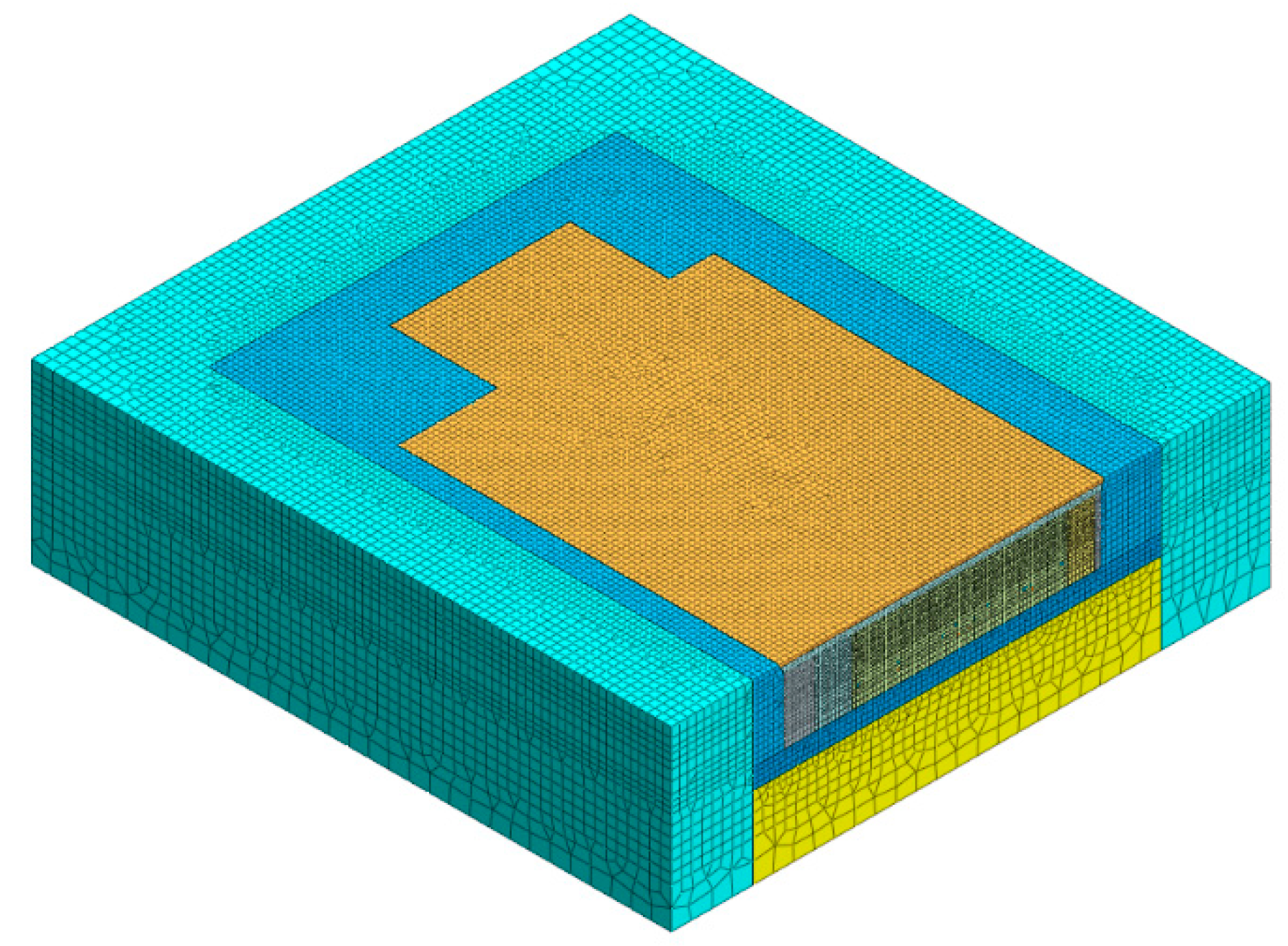
3.1. Geometric Dimensions and Boundary Conditions of the Model

In this paper, a three-dimensional numerical simulation model is established based on the foundation pit construction drawing, as shown in Figure 3. Considering the influence zone of the foundation pit, the size from the foundation pit boundary to the model boundary should not be less than three times the excavation elevation. The depth range is three times the depth of the foundation pit and two times the depth of the column [22]. Combined with the foundation pit construction drawing, a three-dimensional numerical simulation model was established, as shown in Figure 3. The model is 470 m long, 440 m wide, and 130 m high. The top of the model is a free boundary, the normal displacement constraints are set around the model, and the bottom is a fixed boundary.

3.2. Soil and Structure Model

The modified Mohr–Coulomb constitutive model is used in the above numerical model to simulate the soft soil layer. The soil in this range adopts the modified Mohr–Coulomb constitutive model as the solid unit. The internal structure of foundation pit, such as the column and underground diaphragm wall, adopts the elastic constitutive model. The stiffness parameters of the modified Mohr–Coulomb constitutive model suitable for the sandy region were obtained through parameter analysis, and the results are shown in Table 1. The shell element of numerical software is used to simulate the structure of the underground diaphragm wall.
The ground wall is used, that is, the internal lining unit is the shell unit, and the bending rigidity per meter is EI = 2.1 × 10⁶ kN·m2. Since it is difficult for structural elements to directly reflect the forces between piles and soil, and because their limiting side friction resistance needs to be manually calculated and input, in order to better reflect the influence of engineering piles on the deformation of foundation pit, solid elements are used to simulate the pile structure in foundation pit, and its elastic modulus is 24 GPa. Considering the effects of cracking of concrete and repeated use of steel supports, the stiffness parameters of all structures are reduced by 20% from the standard values [23]. The internal structure of the foundation pit, the foundation reinforcement, and the dewatering in the pit are completed before the excavation of the foundation pit, and the excavation sequence is carried out in the order of first supporting and then digging. The corresponding relationship between site construction time and simulated construction conditions is shown in Table 2.

3.3. Space-Time Deformation Analysis of Foundation Pit Structure

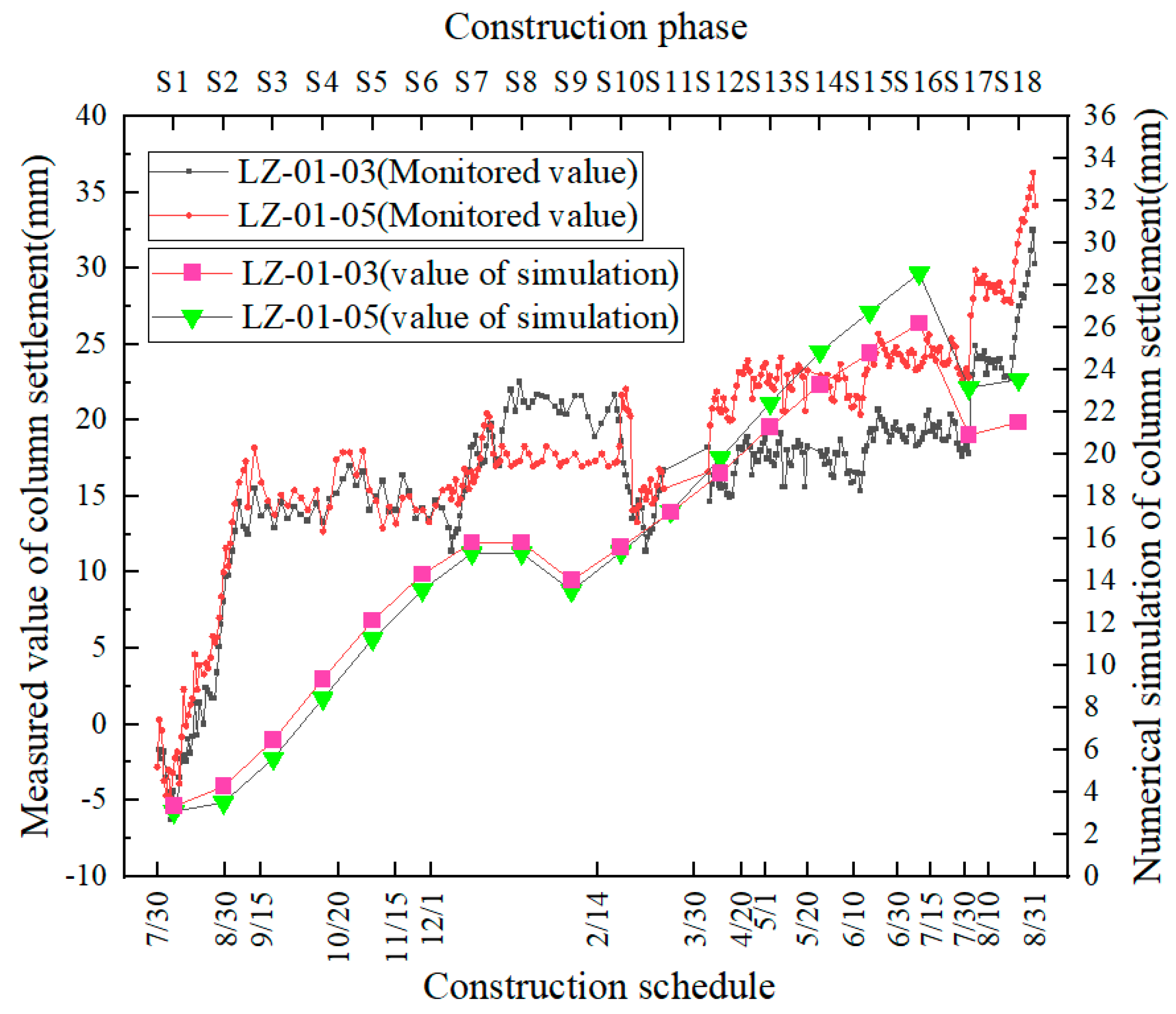
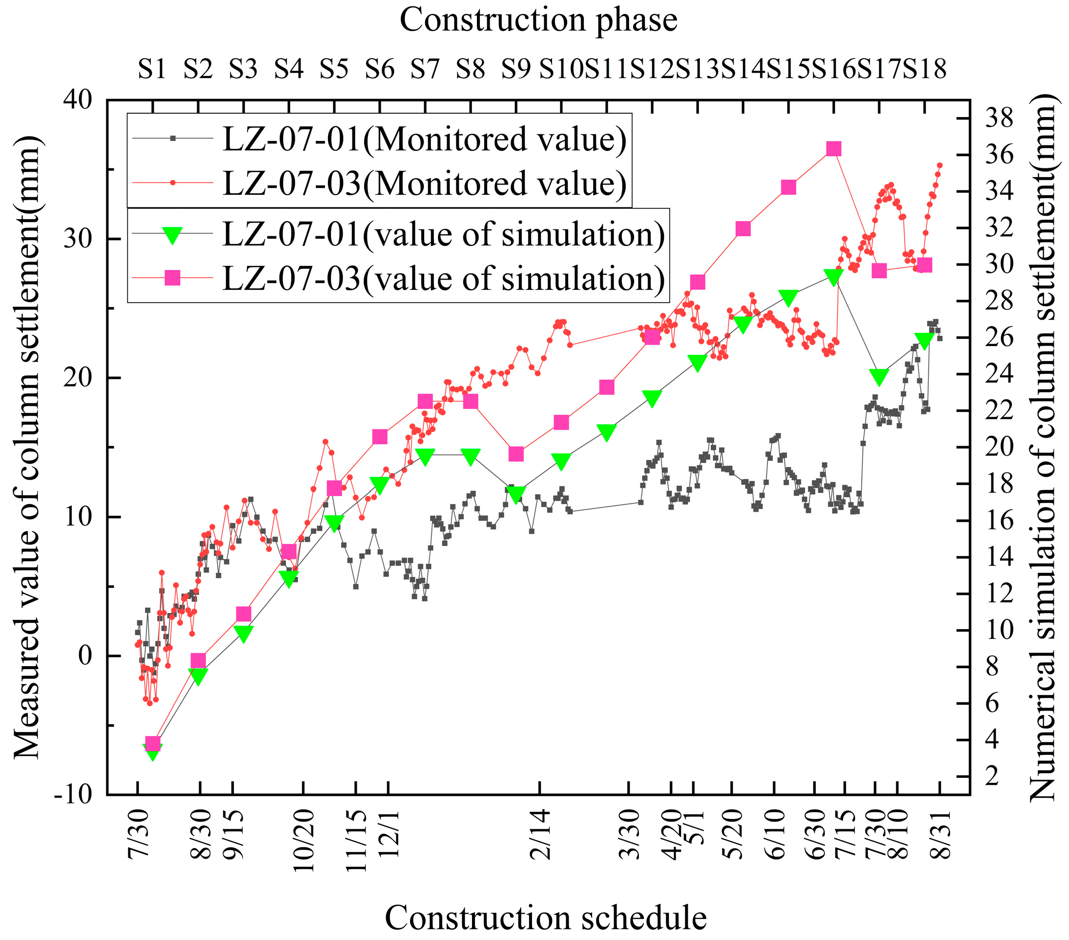
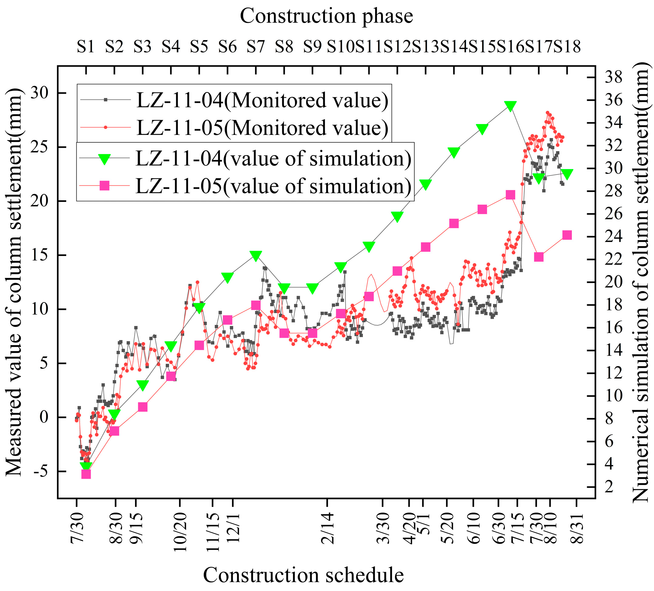
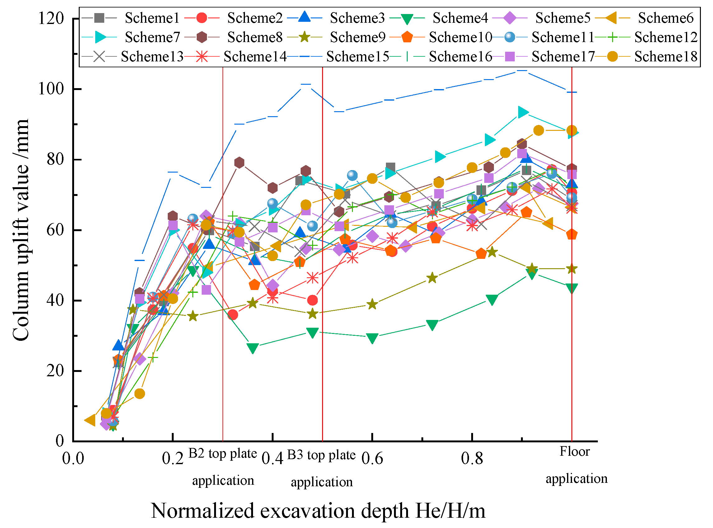
3.3.1. Foundation Pit Column

The omnidirectional displacement meter is used to monitor the structural deformation inside the foundation pit and the surrounding surface settlement. The actual deformation monitoring values and numerical simulation values of columns and ground walls at different positions in the foundation pit during construction are shown in Figure 4, Figure 5 and Figure 6. It can be seen that the numerical simulation results and monitoring data have a high agreement, indicating that the established finite element simulation model can better reflect the deformation characteristics of the structure in the ultra-large deep foundation pit.
From the elevation of 13 m to the top plate of B3, the construction sequence is spatially expressed as earth excavation from top to bottom and from east to west. In the early stage of construction, the excavation of the eastern part of the foundation pit was carried out first. As a result, the vertical deformation amplitude of the No. 3 and No. 5 columns in section 1-1 was larger than that of the columns in the other two sections, and the total uplift deformation reached 20 mm and 23 mm, respectively. The total deformation of the column in sections 7-7 and 11-11 is between 9 mm and 12 mm.
With the earth excavation in the middle and west of the foundation pit, the total deformation of the column at the position of section 1-1 is 3 mm and 6.7 mm, respectively, and the total deformation of the column in sections 7-7 and 11-11 is between 5.2 mm and 8 mm. The amount of deformation is smaller than that of the previous construction stage, and the deformation rate is 3–4 times lower than that of the previous stage. The main reason is that when earthwork excavation is carried out, B3 roof pouring construction and B2 roof forward construction are carried out in the foundation pit. Deformation constraints are imposed on the bottom of the foundation pit. At the same time, the B2 forward slab and the B3 reverse slab are combined with the column to form the overall structure of the foundation pit, which can effectively restrain the unloading and rebound phenomenon of the foundation pit bottom caused by the surrounding earthwork excavation. It can effectively inhibit the uplift and deformation of the column, and the construction time at this stage is twice the construction time of the eastern excavation of the foundation pit; as the construction time is longer, the soil at the bottom of the pit has enough time to release the stress, and the deformation rate of the overall column monitoring point is controlled at about 0.1 mm/d.
The excavation was carried out under the roof of layer B3 (elevation 0 m) to 2 m above the foundation plate (elevation −11 m), and the deformation of the columns of the three monitoring profiles decreased from east to west. By observing the foundation pit plan, it can be seen that the excavation length-width ratio of the foundation pit section gradually decreases from east to west, and the load of earthwork also decreases correspondingly, resulting in low uplift deformation at the bottom of the pit.
The actual deformation monitoring values and numerical simulation values of the columns and ground walls at different positions in the foundation pit along with construction are given in Figure 4, Figure 5 and Figure 6. It can be seen that the numerical simulation results and monitoring data have a high agreement, indicating that the established finite element simulation model can better reflect the deformation characteristics of the structure in the ultra-large deep foundation pit.
To better reflect the rule between column deformation and construction, the statistical data of the maximum uplift value Vlz of each column in different construction stages along with the excavation depth He are given, as shown in Figure 7. The comparison with relevant research results shows that the maximum value of column uplift caused by excavation in the foundation pit is roughly distributed between 0.54‰ and 0.65‰ He, which is greater than the value of column uplift range in the Shanghai hard clay area calculated elsewhere in the literature [7,24,25]. The reason for this phenomenon is that the foundation pit is located in the sandy soil layer, and the unloading modulus of sand is smaller than that of clay. At the same time, the mass of the foundation pit is large, and the unloading load of earth excavation is much larger than that of the foundation pit mentioned in the above references. At the same time, the project area has more rain during the construction stage, the sand moisture content increases, the pore water pressure increases, the effective stress decreases, and the friction resistance of pile end and pile side decreases. To sum up, the uplift deformation of the foundation pit column is large.

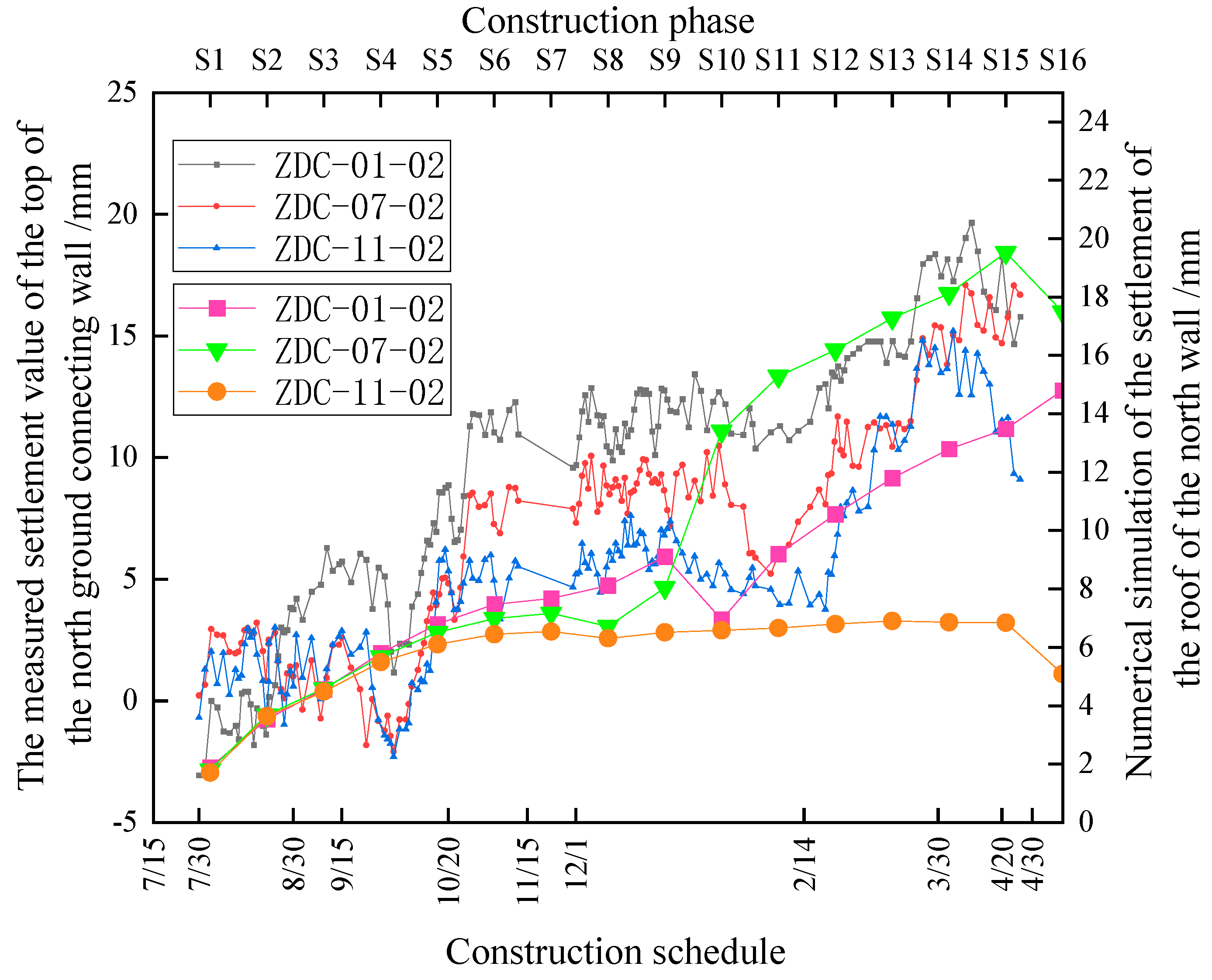
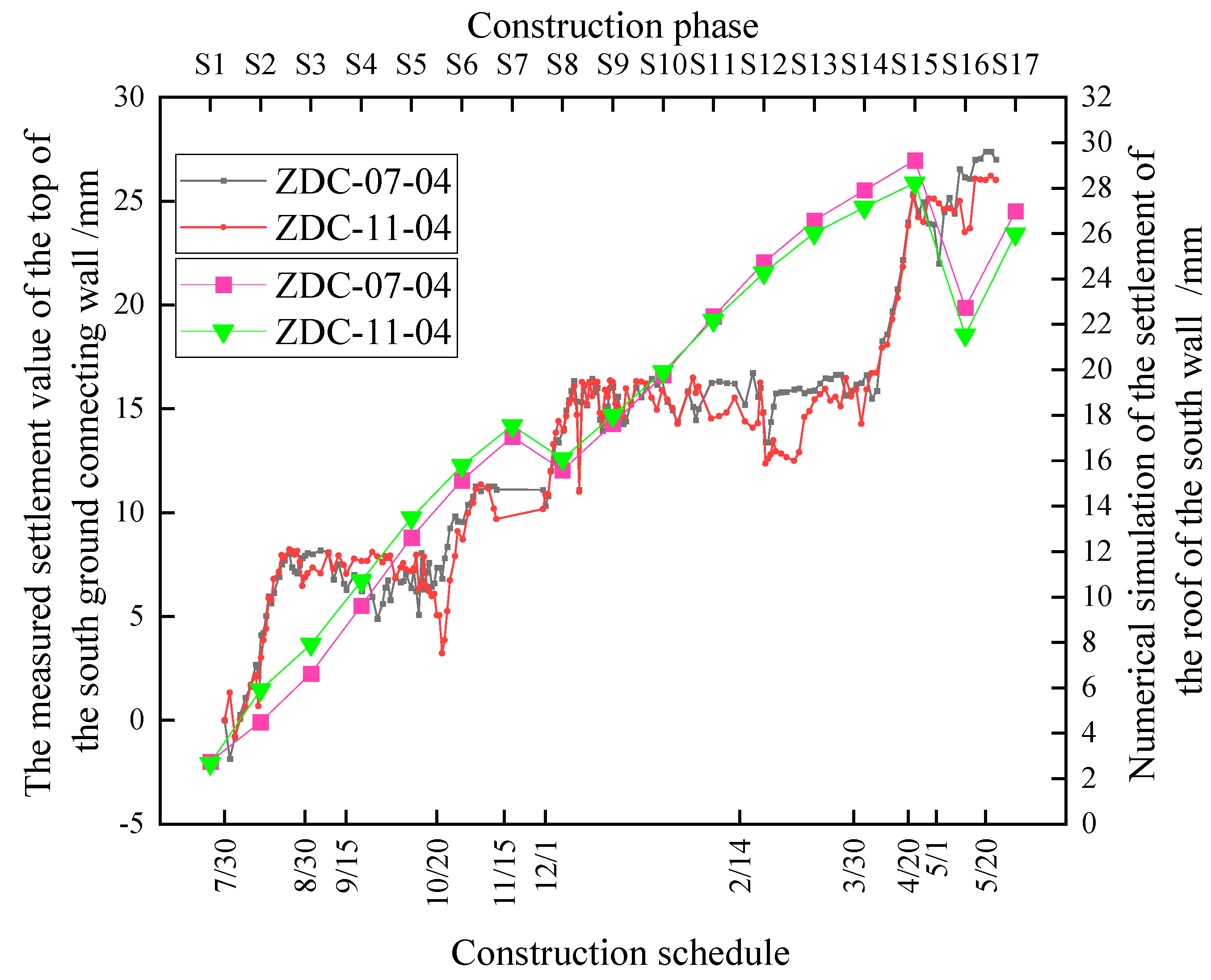
3.3.2. Foundation Pit Is Connected to the Wall

In the early earthwork excavation process, the deformation of the top of the northern wall is more stable than that of the southern wall, and it shows obvious “lag”. The final settlement value of the top of the northern wall is half that of the final settlement value of the southern wall, and the displacement modes of the northern and southern wall are, respectively, translational mode (T) and rotation mode around the bottom (RB) [25,26] (Figure 8 and Figure 9). The main reason is that the uplift and subsidence deformation of the ground connecting wall is caused by the potential sliding body at the foundation pit bottom, while the earth unloading operations are carried out on both sides of the northern ground connecting wall, and the deformation amplitude of the sliding body at the bottom of the foundation pit is smaller than that of the southern ground connecting wall with only one excavation side, and the northern foundation pit has stronger anti-uplift and deformation ability. It can be seen that controlling the displacement and deformation mode of the wall can control the deformation of the envelope structure. In the construction stage of roof and floor pouring, the integrity of the structure is enhanced because of the large roof and floor pouring, and the settlement deformation of the wall is caused by the self-weight of the wall.
As can be seen from Figure 10, the vertical displacement of the ground connecting wall ranges from 0.3‰ to 0.9‰. By comparing the deep foundation pit project in Hangzhou soft clay area [24], Shanghai Metro station project [7,27], and Shanghai ultra-deep shaft excavation [28], the vertical deformation of the wall top caused by foundation pit construction is significantly greater than that of the existing foundation pit project. The main reasons for this phenomenon are as follows: (1) the excavation load of the super-deep foundation pit is large, the unloading modulus of soil in the foundation pit is low, and the soil outside the wall will slide and deform. On the other hand, the supporting structure of the foundation pit converges and deforms from the middle to the corner of the pit, resulting in an obvious corner effect. At the same time, because the embedment of the ground connecting wall is relatively small, the supporting structure produces translation mode (T), and the ascending settlement value of the ground connecting wall is small.

3.3.3. Spatio-Temporal Deformation Analysis of Land Surface Subsidence

In Figure 11 and Figure 12, the deformation monitoring values and numerical simulation values of the surface settlement and displacement monitoring points at different profile positions of the foundation pit during the whole construction process are given, in which the positive is the settlement and the negative is the uplift. As can be seen from the figure, the deformation monitoring values and numerical simulation values of the north and south surfaces both show several shape deformation characteristics, indicating that the established finite element simulation model can better reflect the deformation characteristics of the structure in the super-deep foundation pit. With the excavation and the construction of the foundation pit, the settlement deformation value increases first, then decreases and then increases, and the settlement rate increases when the settlement deformation decreases. On the one hand, due to the reduction of earthwork excavation rate, sand has the “lag” of stress transfer [29,30], and the surrounding soil has sufficient time to release the stress. In addition, due to the application of each floor, the flexural deformation of foundation pit envelope can reduce the settlement deformation of surface soil.
To better show the deformation law of surrounding surface settlement with excavation construction, Figure 13 shows the maximum δvmax of surface settlement at each excavation depth and its relationship. Compared with relevant research results, it can be seen that the surface settlement caused by the excavation of this super-large deep foundation pit ranges from 0.2% to 2.3% He. The upper limit is much larger than Clough [31] and Tan [32] Tan Statistical range of surface subsidence in hard clay strata and Xu Zhonghua [27]. The statistical surface settlement range is similar to the deep underground foundation pit engineering in the soft soil area of Shanghai, but the lower limit meets the distribution of foundation pit specifications [33] The recommended surface settlement control value when the environment level is 1, where the upper limit of surface settlement is located on the north side of the foundation pit, and the lower limit is located on the south side of the foundation pit [29].
Figure 14 shows the distribution of the post-pit surface settlement perpendicular to the envelope structure, where δv/δvmax is the ratio between the surface measuring points outside the pit at each construction stage and the maximum settlement deformation during the total construction process, and S/He is the ratio between the surface measuring points outside the pit and the final construction depth. Through comparison with other existing engineering experience curves [27,31,32,33], it can be found that the main influence range of surface settlement and deformation in this project is within four times the excavation depth (He), and the reasons for this are analyzed as follows: (1) The maximum excavation depth of the foundation pit is 35 m. Compared with the conventional deep foundation pit, the dewatering depth of the foundation pit before excavation is nearly doubled, and the dewatering results in the early deformation of the foundation pit envelope and the significant influence of the ground settlement around the foundation pit; (2) The foundation pit is 350 m long and 120~190 m wide. Compared with other foundation pits, which are generally less than 100 m × 100 m in size, the transverse flexural span of the retaining wall structure of the super-deep foundation pit in this paper is obvious, and the soil outside the pit has a relatively large tendency to slip into the pit. Meanwhile, due to the large embedment of the retaining wall, the retaining wall structure of foundation pit still produces a large lateral displacement, which represents the RB displacement pattern; (3) Most of the foundation pit is located in the sandy or silty soil layer, which has small shear strength and large saturation, resulting in a large range of shear slip planes. Therefore, in the design and construction of this kind of super deep foundation pit, it is recommended to strengthen the preliminary dewatering planning, and reasonable planning dewatering should be carried out in combination with on-site monitoring and theoretical analysis. Second, the lateral constraint and longitudinal support should be strengthened as much as possible in the design of the parapet structure to reduce the transverse deflection span ratio of the parapet structure. Finally, the embedment ratio of the retaining wall should be properly reduced, and the influence of the shear strength and saturation of the soil on the surrounding surface settlement should be considered in the design.
Figure 15 shows the relationship between the maximum surface settlement and the wall top settlement. The maximum surface settlement δvmax on the north side lies between 1.43% and 3.02V%wm, and the maximum surface settlement δvmax on the south side lies between 0.1% and 1.43%Vwm.

4. Influence of Construction Method on Foundation Pit Deformation

4.1. Orthogonal Design

In this paper, orthogonal experiments [34] are used to study the influence of different construction engineering and hydrogeological conditions on the internal structure deformation and the surrounding surface settlement value during the construction of foundation pit. Six excavation design parameters, namely foundation pit depth, precipitation amplitude, length-width ratio, vertical and horizontal spacing of the column, column length, and column diameter, are selected as influencing factors to design the orthogonal test of L18, as shown in Table 3.
The deformation at the corresponding structure and position in the last stage of extracting the numerical model is shown in Table 4.
Range analysis is the difference between the maximum value and the minimum value of each level factor, which indicates the influence of each factor on the performance at different levels. The calculation formula is as follows:
B ij = m = 1 n K i j , m n
where: K i j , m is the first calculation result of factor j under level i ; n is the level number. R i represents the difference between B i j maximum and minimum values at each level:
R i = max B i j min B i j

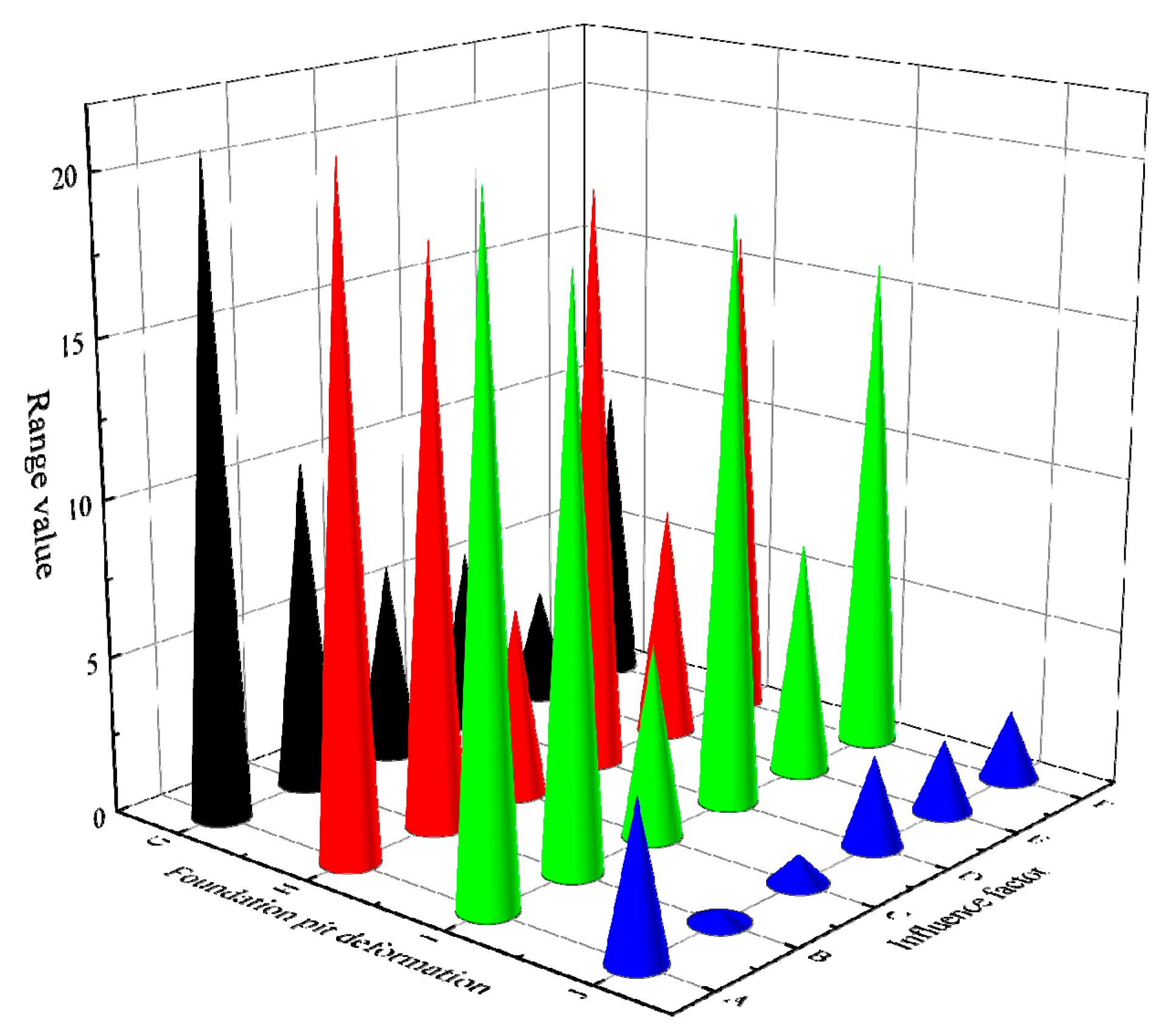
4.2. Analysis of Deformation Sensitive Factors of Foundation Pit Column

From the observation of Figure 16 and Figure 17, it can be seen that the order of factors affecting the uplift deformation of the column inside the foundation pit is depth > groundwater level > column diameter > length-to-width ratio > column spacing > column length. At the same time, the excavation depth of the foundation pit is positively correlated with the uplift deformation of the column, while the other five factors are all negatively correlated, and the impact of reducing the groundwater level is the most obvious. The decrease of the groundwater level reduces the side friction resistance between pile and soil, and reduces the ability of the column to resist the uplift deformation caused by the unloading rebound of soil. With the increase of pile diameter ratio, the area replacement rate between pile and soil increases, and the stress ratio of pile and soil decreases, which is more conducive to the coordinated displacement and deformation of pile and soil and can control the uplift and deformation of the column [35]. At the same time, the application of the vertical plate, the reverse plate, and the bottom plate can enhance the integrity of the inner enclosure structure of the foundation pit and can use the self-weight of the structure to restrain the uplift and deformation of the column (Figure 18).

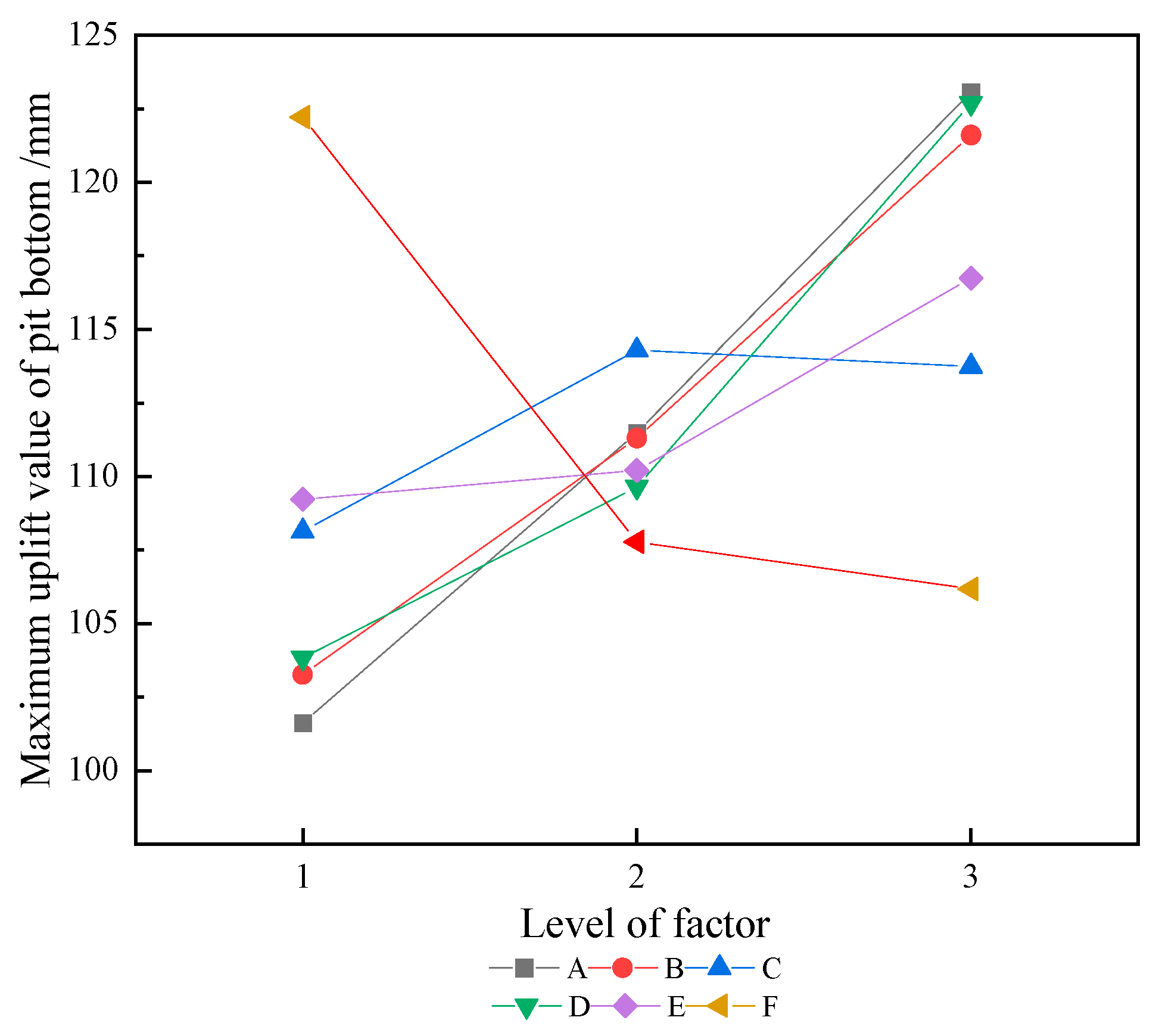
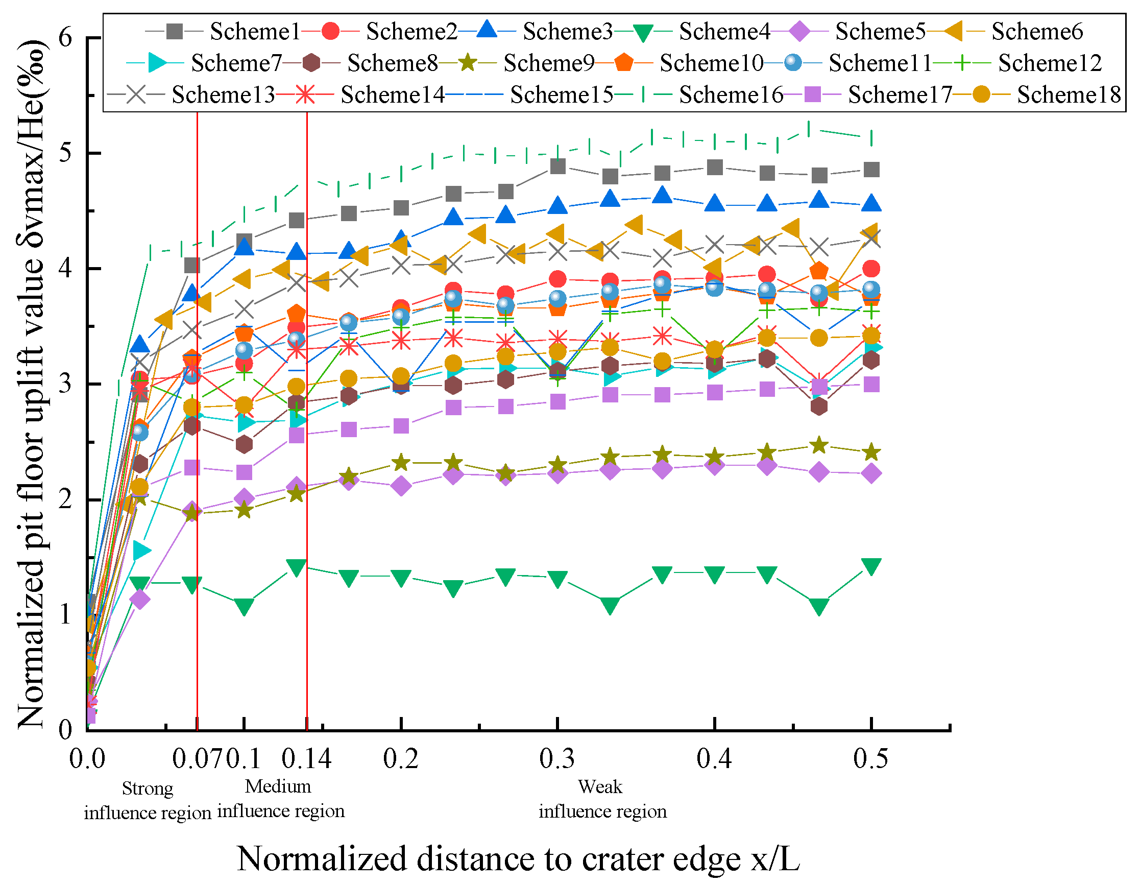
4.3. Analysis of Sensitive Factors of Soil Heave at Pit Bottom

From the observation of Figure 16 and Figure 19, it can be seen that the order of influencing factors of soil uplift deformation at the bottom of the pit is depth of foundation pit > column spacing > groundwater level > column diameter > column length > length-to-width ratio. The relationship between column diameter and soil uplift deformation at the bottom of the pit is negatively correlated, while the other five influencing factors are all positively correlated. With the decrease of column spacing and the increase of column diameter, the interaction between pile and soil is enhanced, and the stiffness of pile and soil is increased, which can reduce the rebound of soil at the bottom of pit caused by soil excavation and unloading. In addition, through timely precipitation treatment, on the one hand, the saturation in the soil body can be reduced to improve the shear strength of the sand and enhance the stiffness of the bottom soil. On the other hand, the seepage and consolidation of the soil in the impervious layer can reduce the uplift and deformation of the soil at the bottom of the pit. At the same time, the soil heave at the bottom of the pit has a “corner effect”. The deformation of the soil heave at the corner of the ground wall is more serious, and the change of soil heave at the bottom of the pit is not obvious with the gradual distance from the ground wall. According to Figure 20, the areas of strong, medium, and weak influence of bottom uplift after foundation pit excavation are (0~0.07) × L, (0.07~0.14) × L, and (0.14~0.5) × L, respectively.

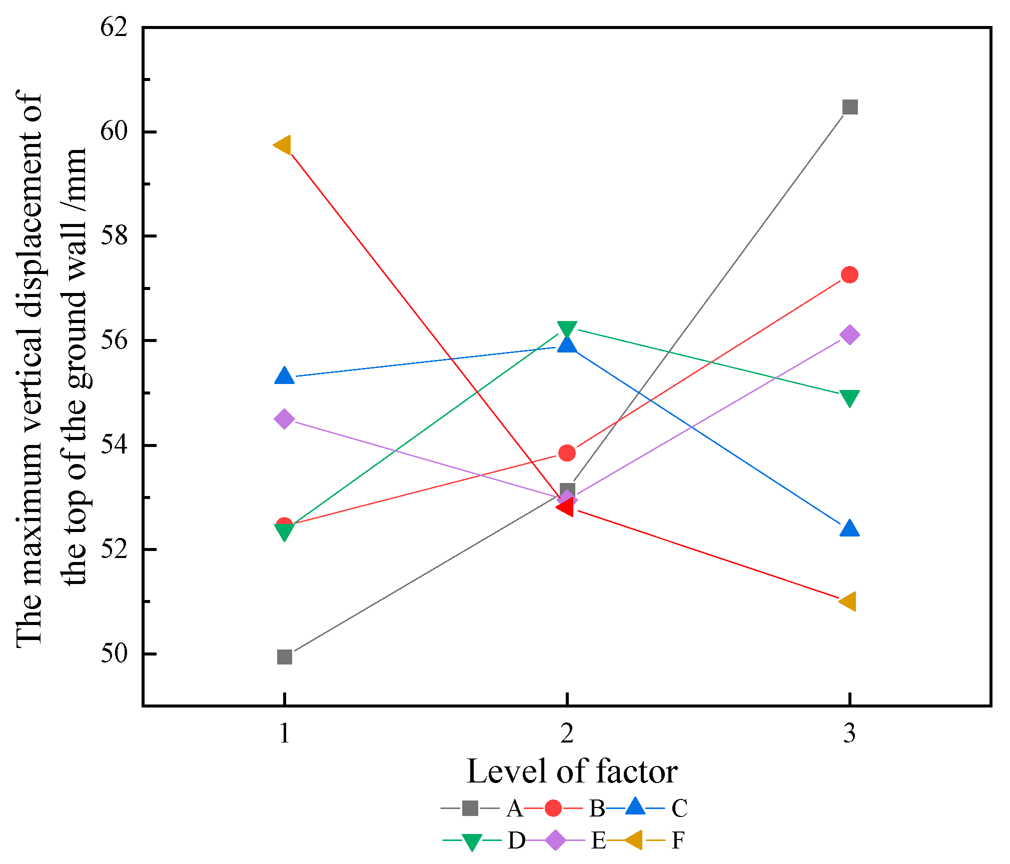
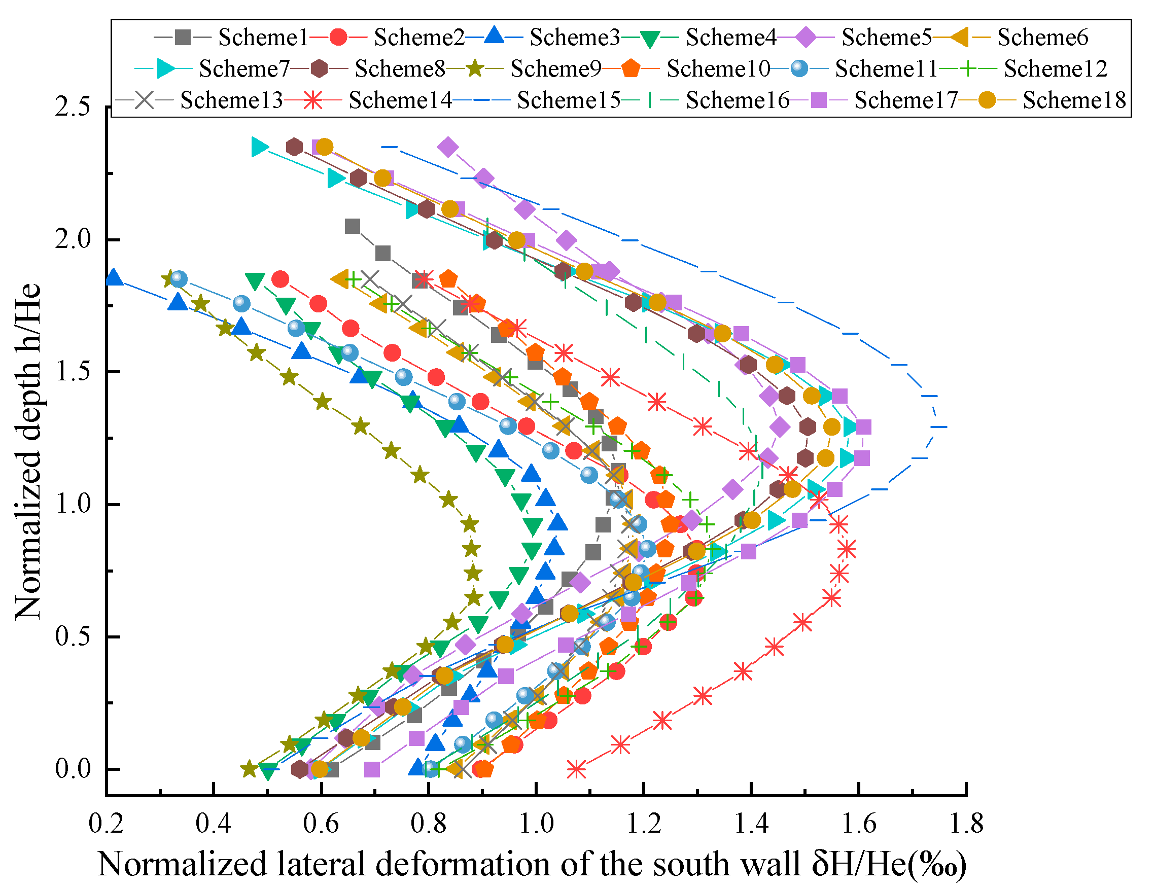
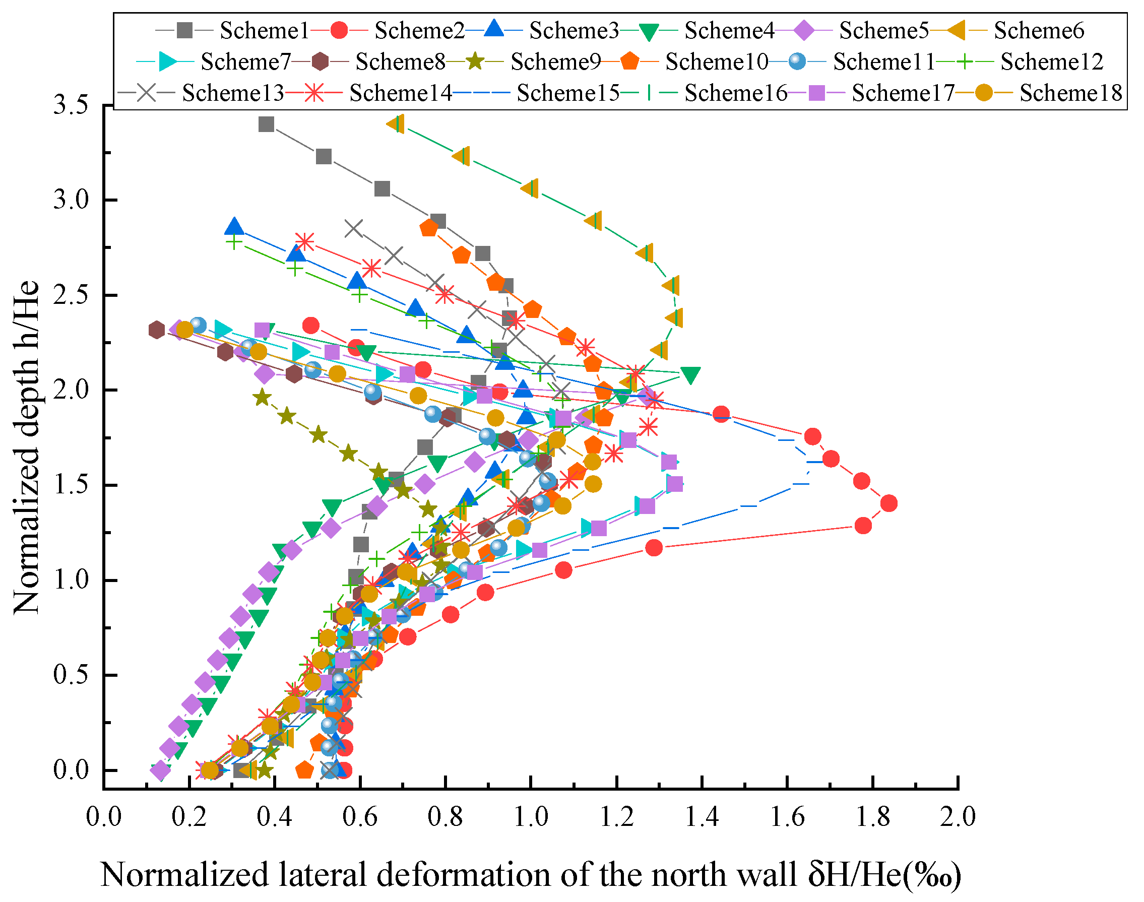
4.4. Analysis of Deformation Sensitive Factors of Foundation Pit Connecting Wall

According to Figure 16 and Figure 21, it can be seen that the influencing factors of foundation pit wall settlement deformation are in the order of foundation pit depth > column diameter > groundwater level > column spacing > length-to-width ratio > column length. The excavation depth of the foundation pit is positively correlated with the settlement deformation of the foundation pit wall, while the other five influencing factors are all negatively correlated. The main reason for the settlement and deformation of the ground joint wall is that the earth pressure behind the wall is acted on by excavation and unloading, which causes the ground joint wall to bend and the sliding body in the foundation of the ground joint wall, thus driving the whole deformation of the wall.
In addition, the lateral displacement diagram of the north-south ground connecting wall shows that with excavation (Figure 22 and Figure 23), when the embedment ratio is between 1.8–2.4, the retaining wall structure will undergo translational mode (T) displacement, and when the embedment ratio is between 2.4–3.4, the retaining wall structure will undergo rotation mode (RB) displacement around the bottom. With the increase of the embedment ratio, the displacement mode of the retaining wall changes, resulting in the upward movement of the active earth pressure and the maximum lateral displacement position of the retaining wall structure.

4.5. Analysis of Sensitive Factors of Ground Settlement Around Foundation Pit

From the observation of Figure 16 and Figure 24, it can be seen that the order of influencing factors of ground surface settlement around foundation pit is depth of foundation pit > column spacing > column length > column diameter > length-width ratio > groundwater level. The excavation depth of foundation pit is positively correlated with the relationship between pit bottom between column spacing and ground surface settlement around foundation pit, while the other four influencing factors are all negatively correlated. Part of the surface settlement is caused by the flexural deformation of the ground connecting wall caused by the unloading action of foundation pit excavation and the displacement of the soil at the edge of the pit. In addition, because the soil in the area is affected by the foundation pit bottom, when the length of the column pile is small, the pile will produce a large horizontal rigid displacement with the pile soil. The increase of the proportion of column piles in the weak influence zone can effectively inhibit the displacement of the upper pile, and the inhibition effect of engineering piles on the horizontal displacement of the ground connecting wall is enhanced. With the increase of column spacing, the “pile group effect” between the column pile and the soil is weakened, the stiffness of the soil at the bottom of the pit decreases, the bending ability decreases, the flexural degree of the ground wall increases, and the surrounding surface settlement increases.

5. Discussion

(1)
Although the temporal and spatial deformation characteristics of ultra-deep foundation pits in sandy areas are obtained through comparative analysis of some existing foundation pit cases, more engineering examples are needed for analysis and verification. In addition, the mechanisms affecting the temporal and spatial deformation of the super deep foundation pit have not been explained, and further research needs to be carried out through laboratory experiments and field monitoring.
(2)
The orthogonal experiment only considers the influence of the excavation process and hydrogeological conditions on the deformation characteristics of foundation pit and does not consider the influence of different internal supporting structures and construction methods on the deformation characteristics of foundation pit.
(3)
Because of the complex groundwater conditions, sand is more sensitive to water. In a subsequent study, the author will consider the influence of fluid-structure coupling effect on the numerical simulation results.

6. Conclusions

Based on field monitoring data and numerical simulation analysis, this paper studies the temporal and spatial deformation characteristics of the super-deep foundation pit in the thick sandy soil area of Beijing, and, combined with the orthogonal experiment, analyzes the influence degree of different construction conditions and hydrogeological conditions on the internal structure deformation of the foundation pit and the surrounding surface settlement:
(1)
Because most of the foundation pit project is located in the sandy soil, and because the compressibility of the sand itself is relatively large, under the condition of water, the rebound deformation of the foundation and the uplift of the column caused by the soil excavation are significantly larger than that under the condition of no water. The maximum deformation value of the column is between 0.54‰ and 0.65‰ He. For the construction of the super deep foundation pit, the construction method of partition excavation, digging first and then supporting, can effectively alleviate the large deformation of the internal structure of the foundation pit due to excessive unloading.
(2)
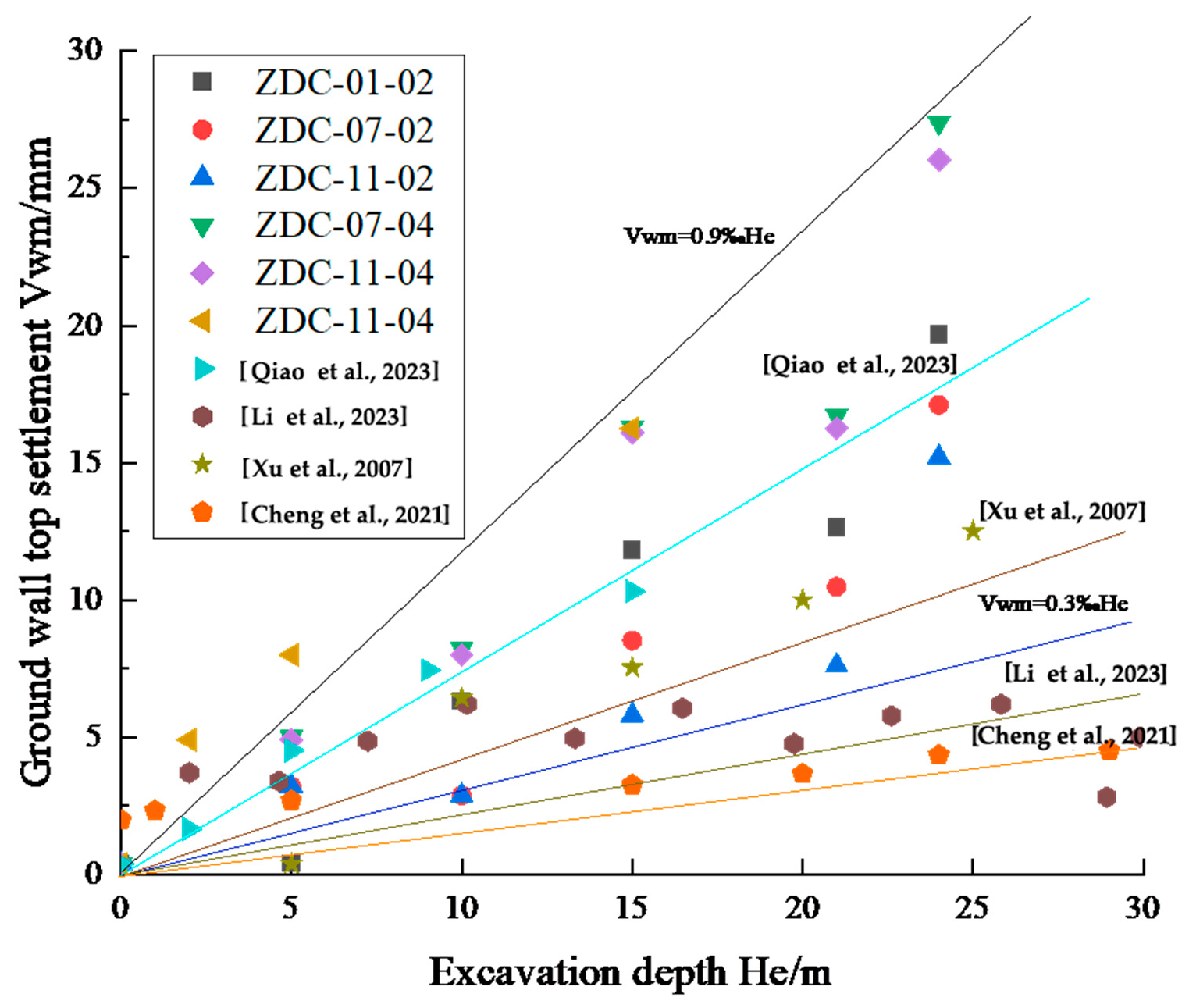
Due to the different embedment ratio, the displacement modes of the ground connecting wall on the north and south sides of the foundation pit are, respectively, translational mode (T) and rotation mode around the bottom (RB). The deformation generated by rotation mode around the bottom is twice that of the translational mode, and the vertical displacement Vwm of the ground connecting wall ranges from 0.3‰ to 0.9‰ He.
(3)
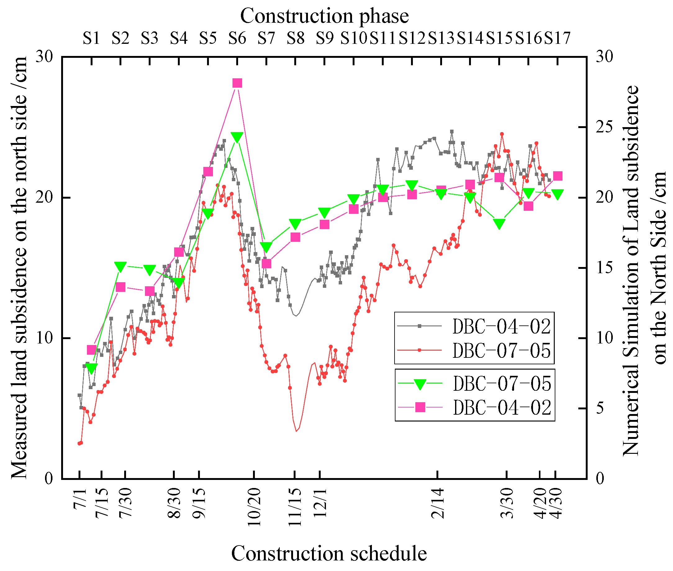
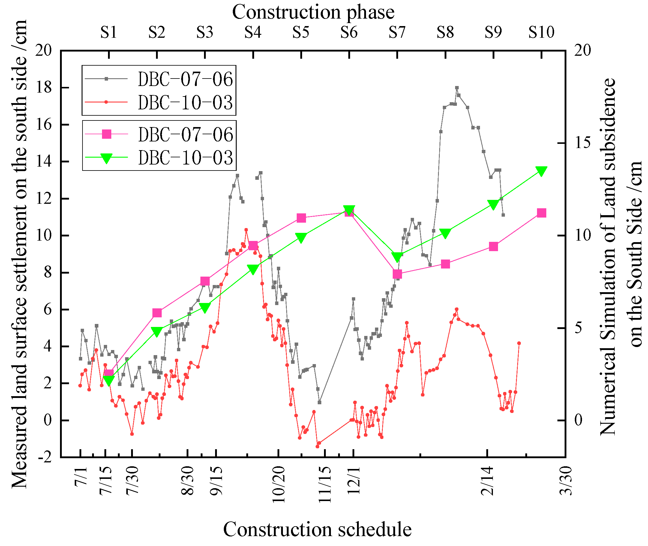
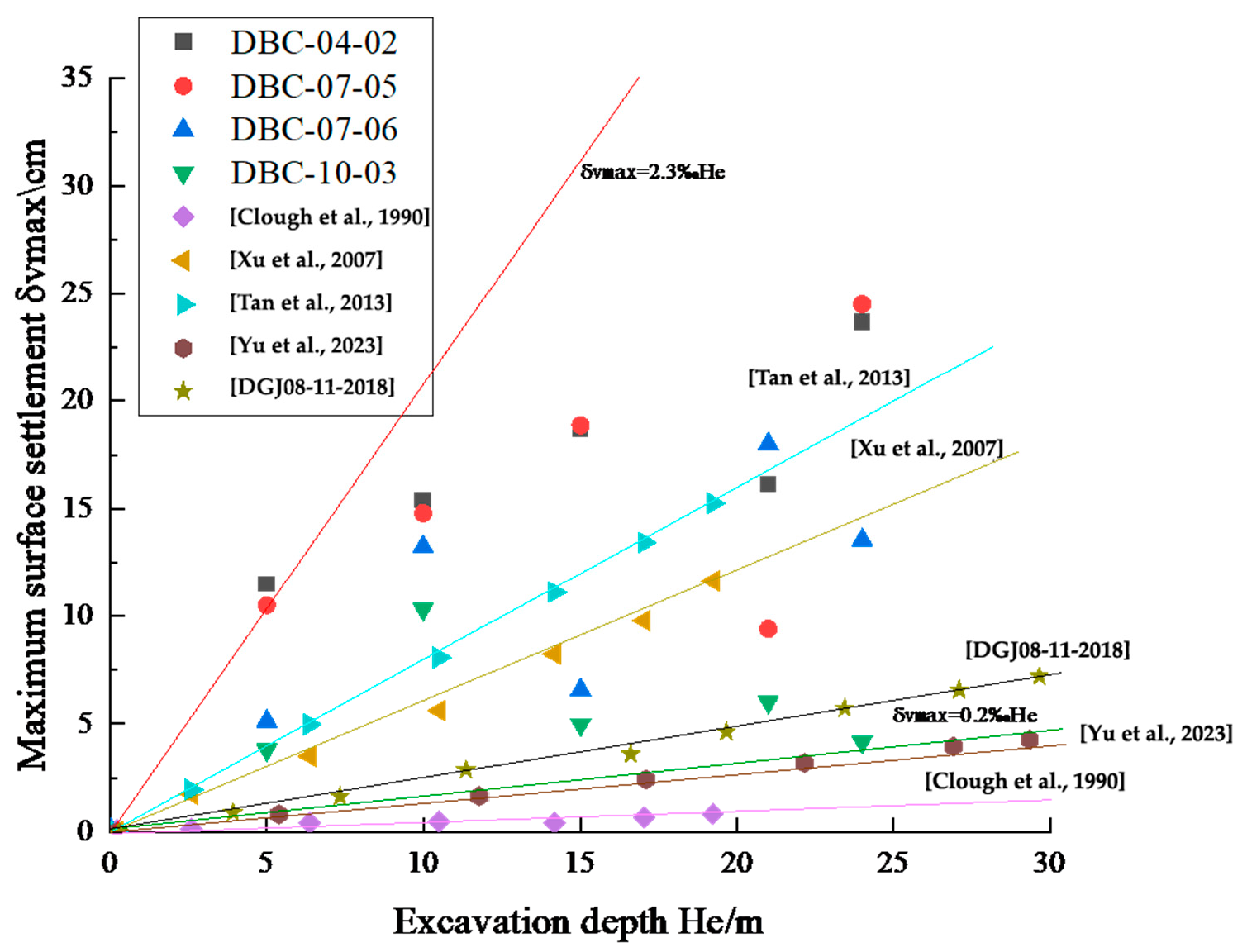
Due to the “hysteresis” of stress transfer in sand, the settlement deformation value first increases, then decreases, and then increases, and the settlement rate increases after the settlement deformation decreases. The surface settlement deformation in the north and south ranges from 0.2% to 2.3% He, and the influence range of excavation is four times the excavation depth. The transverse constraint and longitudinal support should be strengthened as much as possible in the design of the parapet structure, and the dispersing force can reduce the transverse deflection span ratio of the parapet structure. The embedment ratio of the retaining wall should be reduced appropriately, the displacement mode of the retaining wall should be changed, and the influence of the shear strength and saturation of the soil on the surrounding surface settlement should be considered in the design.
(4)
The sensitivity of six factors to the deformation of foundation pit structure and its surrounding environment is studied through orthogonal experiments. The deformation of the foundation pit structure and its surrounding environment is more sensitive to the factors of excavation unloading, precipitation amplitude, and column spacing. The main mechanism of foundation pit structure and surrounding surface deformation is soil rebound caused by excavation unloading. Increasing the spacing of columns can increase the force between piles and soils and inhibit the unloading rebound of soils. Timely and orderly dewatering can not only make the soil in the foundation pit produce the unloading compression phenomenon but also make the soil in the impervious layer produce seepage consolidation, which can effectively restrain the deformation trend of the foundation pit.
(5)
Based on the experimental results of 18 groups in this paper, it is concluded that the areas of strong, medium, and weak influence in the pit bottom uplift after foundation pit construction are (0~0.07) × L, (0.07~0.14) × L, and (0.14~0.5) × L, respectively. In addition, when the embedment ratio is between 1.8 and 2.4, the parapet structure is in translational mode (T), and when the embedment ratio is between 2.4 and 3.4, the parapet structure is in rotation mode around the bottom (RB). Reasonable planning and application of the vertical and the reverse slab and bottom plate in foundation pit can effectively restrain the uplift deformation of the column in foundation pit and the deflection deformation of the envelope structure, and reduce the deformation impact on the surrounding environment of foundation pit.

Author Contributions

H.-X.S.: Formal analysis, Investigation, Methodology, Writing—review and editing. P.X.: Writing—review and editing, Supervision, Project administration, Methodology, Funding acquisition, Formal analysis, Conceptualization. Y.-H.Y.: Conceptualization, Data curation. H.-G.J.: Resources, Supervision, Writing—review and editing. W.-D.L.: Conceptualization, Data curation. H.-J.G.: Conceptualization, Data curation. All authors have read and agreed to the published version of the manuscript.

Funding

This research has been selected by the People’s Republic of China “14th Five-Year” national key research and development plan “Strategic mineral resources development and utilization” key special “Underground metal mine broken ore body safe and efficient mining technology and intelligent equipment” project topic 3: Supported by intelligent monitoring technology and equipment of integrated optical and thermal wave for roof deformation of broken ore body in metal mine (2023YFC2907403).

Institutional Review Board Statement

Not applicable.

Informed Consent Statement

Not applicable.

Data Availability Statement

The original contributions presented in this study are included in the article. Further inquiries can be directed to the corresponding authors.

Conflicts of Interest

Authors Ying-Hui Yang, Wei-Dong Liu and Hong-Jun Guo were employed by the company Beijing Urban Construction Group Co., Ltd. The remaining authors declare that the research was conducted in the absence of any commercial or financial relationships that could be construed as a potential conflict of interest.

References

  1. Aljanabi, H.; Imam, R.; Khorand, M. Behavior of model pile in unsaturated soil subjected to cyclic loading. Acta Geotech. 2024, 20, 583–605. [Google Scholar] [CrossRef]
  2. Castaldo, P.; Jalayer, F.; Palazzo, B. Probabilistic assessment of groundwater leakage in diaphragm wall joints for deep excavations. Tunn. Undergr. Space Technol. 2018, 71, 531–543. [Google Scholar] [CrossRef]
  3. Zhang, W.S.; Yuan, Y.; Long, M.; Yao, R.H.; Jia, L.; Liu, M. Prediction of surface settlement around subway foundation pits based on spatiotemporal characteristics and deep learning models. Comput. Geotech. 2024, 168, 106149. [Google Scholar] [CrossRef]
  4. Houhou, M.N.; Emeriault, F.; Belounar, A. Three-dimensional numerical back-analysis of a monitored deep excavation retained by strutted diaphragm walls. Tunn. Undergr. Space Technol. 2019, 83, 153–164. [Google Scholar] [CrossRef]
  5. Sun, Y.Y.; Xiao, H.J. Wall displacement and ground-surface settlement caused by pit-in-pit foundation pit in soft clays. KSCE J. Civ. Eng. 2021, 25, 1262–1275. [Google Scholar] [CrossRef]
  6. Boscardin, M.; Cording, E. Building response to excavation-induced settlement. J. Geotech. Eng. 1989, 115, 1–21. [Google Scholar] [CrossRef]
  7. Li, H.; Li, Z.; Liao, S.; Li, Z.; Zhong, H. Temporal and spatial distribution characteristics of environmental deformation in ultra-deep foundation pit in Shanghai. Chin. J. Geotech. Eng. 2023, 45, 1595–1604. [Google Scholar]
  8. Zheng, G. Deformation control method and engineering application of foundation pit engineering in soft soil area. J. Rock Soil Eng. 2022, 44, 1–36+201. [Google Scholar]
  9. Wang, D.; Ye, S.; Zhang, J. Risk Reduction Measures and Monitoring Analysis of Deep Foundation Pit with Water in a Metro Station in Hefei. Water 2023, 15, 3007. [Google Scholar] [CrossRef]
  10. Nicotera, M.V.; Russo, G. Monitoring a deep excavation in pyroclastic soil and soft rock. Tunn. Undergr. Space Technol. 2021, 117, 104130. [Google Scholar] [CrossRef]
  11. Zhao, Y.; Chen, X.; Hu, B.; Huang, L.; Lu, G.; Yao, H. Automatic monitoring and control of excavation disturbance of an ultra-deep foundation pit extremely adjacent to metro tunnels. Tunn. Undergr. Space Technol. 2023, 142, 105445. [Google Scholar]
  12. Dong, Y.; Luan, Y.; Wang, F.; Yang, H.; Jia, Z.; Luan, H. Monitoring and prediction of horizontal displacement of underground enclosure piles in subway foundation pits. ACS Omega 2023, 8, 23389–23400. [Google Scholar] [PubMed]
  13. Zhang, Q.; Ma, Y.; Zhang, B.; Tian, L.; Zhang, G. Time Series Prediction on Settlement of Metro Tunnels Adjacent to Deep Foundation Pit by Clustering Monitoring Data. KSCE J. Civ. Eng. 2023, 27, 2180–2190. [Google Scholar]
  14. Liu, H.; Liu, X.; Zhou, X.; Wang, L.; Wang, K.; Zhang, J.; Guo, X. Study on Spatiotemporal Evolution Laws and Deformation Characteristics of Circular Deep and Large Foundation Pits in Soft Soils. Arab. J. Sci. Eng. 2024, 49, 1–25. [Google Scholar]
  15. Liu, Z.; Liu, F.; Wang, Y.; Zhang, Y.; Sun, Z.; Zhang, M. Prediction of retaining structure deformation of ultra-deep foundation pit by empirical mode decomposition with recurrent neural networks. Environ. Earth Sci. 2023, 82, 553. [Google Scholar]
  16. Zhou, X.; Pan, Y.; Qin, J.; Chen, J.-J.; Gardoni, P. Spatio-temporal prediction of deep excavation-induced ground settlement: A hybrid graphical network approach considering causality. Tunn. Undergr. Space Technol. 2024, 146, 105605. [Google Scholar]
  17. Zhang, D.M.; Xie, X.C.; Li, Z.L.; Zhang, J. Simplified analysis method for predicting the influence of deep excavation on existing tunnels. Comput. Geotech. 2020, 121, 103477. [Google Scholar] [CrossRef]
  18. Zhang, W.; Zhang, R.; Wang, W.; Zhang, F.; Goh, A.T.C. A multivariate adaptive regression splines model for determining horizontal wall deflection envelope for braced excavations in clays. Tunn. Undergr. Space Technol. 2019, 84, 461–471. [Google Scholar] [CrossRef]
  19. Zhang, X.; Liu, S.Y.; Wu, K.; Cai, G.J.; Lu, T.S. Numerical analysis of influences of engineering piles on rebound deformation of foundation pit. Chin. J. Geotech. Eng. 2021, 43, 11–14. [Google Scholar]
  20. Leng, W.; Yao, K.; Men, X.; Xu, F.; Su, H.; Chan, J.; Ye, X. Analysis of deformation characteristics of deep foundation pit considering engineering pile effect. J. Railw. Sci. Eng. 2023, 20, 1347–1358. [Google Scholar]
  21. Li, H.; Ren, G.; Shen, G.; Fan, R.; Zeng, W.; Dong, B. Research on deformation control and response of deep foundation pit under complex environment. J. Chengdu Univ. Technol. (Nat. Sci. Ed.) 2023, 50, 744–755. [Google Scholar]
  22. Liu, G.; Wang, W. Foundation Pit Engineering Manual; China Building and Construction Press: Beijing, Beijing, 2009. [Google Scholar]
  23. Lim, A.; Ou, C.Y.; Hsieh, P.G. Evaluation of clay constitutive models for analysis of deep excavation under undrained conditions. J. Geo Eng. 2010, 5, 9–20. [Google Scholar]
  24. Cheng, K.; Xu, R.; Ying, H.; Li, B.; Gan, X.; Qiu, Z.; Zhan, X.; Qin, J. Experimental analysis of excavation behavior of a 30.2-m deep foundation pit in Hangzhou soft clay area. Chin. J. Rock Mech. Eng. 2021, 40, 851–863. [Google Scholar]
  25. Ying, H.; Zhu, W.; Zheng, B.; Wang, G. Calculation and distribution of active earth pressure on flexible retaining wall. Chin. J. Geotech. Eng. 2014, 36, 1–6. [Google Scholar]
  26. Rui, R.; Jiang, W.; Xu, Y.; Xia, R.; Edo, E.E.; Ding, R. Rigid retaining wall displacement model experimental study on the influence of soil pressure. J. Rock Mech. Eng. 2023, 42, 1534–1545. [Google Scholar] [CrossRef]
  27. Xu, Z. Study on Deformation Behavior of Deep Foundation Pit Combined with Supporting Structure and Main Underground Structure in Shanghai Area. Ph.D. Thesis, Shanghai Jiao Tong University, Shanghai, China, 2007. [Google Scholar]
  28. Qiao, Y.; Yan, K.; Zhao, T.; Ding, W. Soft soil area uplifts of characteristics and mechanism of super deep circular shaft. Rock Soil Mech. 2023, 44, 2707–2716. [Google Scholar] [CrossRef]
  29. Yu, H.; Li, S.; Wan, Y.; Guo, L.; Chen, Z. After add uninstall circular retaining wall under the sand, the three-dimensional stress state test study. J. Civ. Eng. 2023, 56, 35–42. [Google Scholar]
  30. Liang, L.; Xu, C.; Fan, X.; Chen, Q. Hyperbolic stress-strain behaviour of sandy soil under plane strain unloading condition and its application on predicting displacement-dependent active earth pressure. Comput. Geotech. 2023, 155, 105219. [Google Scholar]
  31. Clough, G.W. Construction Induced Movements of Insitu Wall, Design and Performance of Earth Retaining Structure; ASCE: Reston, VA, USA, 1990. [Google Scholar]
  32. Tan, Y.; Wang, D. Characteristics of a large-scale deep foundation pit excavated by the central-island technique in Shanghai soft clay. I: Bottom-up construction of the central cylindrical shaft. J. Geotech. Geoenvironmental Eng. 2013, 139, 1875–1893. [Google Scholar] [CrossRef]
  33. DGJ08-11-2018; Foundation Designcode. Tongji University Press: Shanghai, China, 2019.
  34. Shen, H.; Kong, Y.; Pang, J. Orthogonal test on strength of ceramide hybrid fiber concrete. J. Yangtze River Sci. Res. Inst. 2021, 38, 144–148. [Google Scholar]
  35. Chen, L.; Chai, Z.; Shen, Z.; Chen, Y.; Xie, C.; Li, D. In situ solidification soil combined pile composite foundation pile soil stress ratio analysis. J. Rock Mech. Eng. 2023, 42, 2578–2587. [Google Scholar] [CrossRef]
Figure 1. Foundation pit plan and monitoring point layout.
Applsci 15 03553 g001
Figure 2. Typical profile of foundation pit (Section 3.3).
Applsci 15 03553 g002
Figure 3. Three-dimensional finite element model.
Applsci 15 03553 g003
Figure 4. 01-01 Profile column monitoring deformation value and numerical simulation value.
Applsci 15 03553 g004
Figure 5. 07-07 Profile column monitoring deformation value and numerical simulation value.
Applsci 15 03553 g005
Figure 6. 11-11 Profile column monitoring deformation value and numerical simulation value.
Applsci 15 03553 g006
Figure 7. Relationship between column deformation and excavation depth [7,24,25].
Applsci 15 03553 g007
Figure 8. The monitoring deformation value and numerical simulation value of the north ground connecting wall.
Applsci 15 03553 g008
Figure 9. The monitoring deformation value and numerical simulation value of the south ground connecting wall.
Applsci 15 03553 g009
Figure 10. The relationship between the settlement of the roof of the ground wall and the depth of excavation [7,24,27,28].
Applsci 15 03553 g010
Figure 11. Surface deformation monitoring and numerical simulation values on the north side.
Applsci 15 03553 g011
Figure 12. Surface deformation monitoring and numerical simulation values on the south side.
Applsci 15 03553 g012
Figure 13. The relationship between the settlement of the roof of the ground wall and the depth of excavation [27,29,31,32,33].
Applsci 15 03553 g013
Figure 14. Surface settlement distribution perpendicular to the direction of the envelope, Xu et al., [27,31,32,33].
Applsci 15 03553 g014
Figure 15. The relationship between the maximum settlement value of the surface and the settlement of the wall top.
Applsci 15 03553 g015
Figure 16. Results of range analysis.
Applsci 15 03553 g016
Figure 17. Analysis of sensitive factors of deformation value of foundation pit column.
Applsci 15 03553 g017
Figure 18. Relation between uplift value of column and normalized excavation depth.
Applsci 15 03553 g018
Figure 19. Analysis of sensitive factors of uplift value of pit bottom.
Applsci 15 03553 g019
Figure 20. Analysis of uplift deformation law of foundation pit bottom.
Applsci 15 03553 g020
Figure 21. Analysis of sensitive factors of uplift deformation of the roof of ground wall.
Applsci 15 03553 g021
Figure 22. Lateral deformation of the south ground wall.
Applsci 15 03553 g022
Figure 23. Lateral deformation of the north ground wall.
Applsci 15 03553 g023
Figure 24. Analysis of sensitive factors of surface deformation.
Applsci 15 03553 g024
Table 1. Basic physical and mechanical parameters of soil layer.
IDAssiseElasticity
Modulus (MPa)
Natural Weight (KN/m3)Saturated Unit Weight (KN/m3)Cohesionc
(KPa)
Frictional Angle
Φ (°)
Modulus of Unloading Rebound (MPa)
Miscellaneous fill4.1418.118.7401012.42
clay6.3118.619.08252518.93
Fine sand4018.622.16028120
Silty clay11.719.923.40103035.1
Fine sand451920.122825135
clay14.61920.00252243.8
Sandy soil26.219.419.8403078.6
Fine sand752020.782725225
Heavy silt clay25.619.920.81232776.8
Sandy silt45.72020.53036137.1
Fine sand35.319.924.25032105.9
Table 2. Foundation pit construction conditions and simulation.
Construction PhaseConstruction StateConstruction Schedule
S1Excavation to elevation 11 m
S2Excavation to elevation 9 m2021/7–2021/11
S3Excavation to 7 m elevation
S4Excavation to 5 m elevation
S5Excavation to elevation 3 m
S6Excavation to elevation 1 m
S7B3 roof pouring2021/8–2021/11
S8Excavation to elevation 0 m2021/11–2022/2
S9Excavation to elevation −2 m
S10Excavation to elevation −5 m
S11Excavation to elevation −7 m
S12Excavation to elevation −9 m
S13Excavation to elevation −11 m
S14Spring Festival shutdown2022/2–2022/3
S15Excavation to elevation −13 m2022/4–2022/9
S16Excavation to elevation −14.5 m
S17B3 Baseplate construction
S18Excavation with reversed soil pressure
Table 3. Orthogonal experiment table.
LevelFactor
Depth of Foundation Pit
(A)/m
Precipitation Level
(B)/m
Length-Width Ratio
(C)
Column Spacing
(D)/m
Column Length
(E)/m
Column Diameter
(F)/m
1208110351
22510414402
33012818453
Table 4. Orthogonal experiment results.
SchemeABCDEFGHIJ
1201211435168.7755.0011.73130.17
2251641435370.6352.0514.98113.76
3201681040172.9752.009.77104.78
4251281040343.7839.4412.0793.78
530811045367.5353.6217.4683.65
6201241045268.8055.0011.70103.00
7301641035287.6357.2716.13111.21
830841840177.3659.9616.59108.79
925881445249.0440.4412.4398.86
1020841440371.7052.9811.73103.02
11251241845169.2058.1313.48101.84
12251611840266.2152.7515.91100.03
1320881835266.9450.8614.7896.66
1425811035171.9656.8614.64101.47
15301681445199.1576.5214.73143.28
16201611845371.6552.9814.54113.60
17301281835375.8554.9523.48102.09
18301211440288.2860.5615.79119.93
Note: G is the maximum uplift value of the column/mm; H is the maximum uplift value of the wall top/mm; I is the maximum surface settlement value/mm; J is the maximum uplift value of pit bottom/mm.
Disclaimer/Publisher’s Note: The statements, opinions and data contained in all publications are solely those of the individual author(s) and contributor(s) and not of MDPI and/or the editor(s). MDPI and/or the editor(s) disclaim responsibility for any injury to people or property resulting from any ideas, methods, instructions or products referred to in the content.

