Article

Development of Surrogate Model for Patient-Specific Lattice-Structured Hip Implant Design via Finite Element Analysis

by
Rashwan Alkentar
1,2,* and
Tamás Mankovits
2
1
Department of Mechanical Engineering, Faculty of Engineering, University of Debrecen, Ótemető u. 2-4., H-4028 Debrecen, Hungary
2
Doctoral School of Informatics, Faculty of Informatics, University of Debrecen, Kassai u. 26., H-4028 Debrecen, Hungary
*
Author to whom correspondence should be addressed.
Appl. Sci. 2025, 15(7), 3522; https://doi.org/10.3390/app15073522
Submission received: 3 March 2025 / Revised: 21 March 2025 / Accepted: 22 March 2025 / Published: 24 March 2025

Abstract

:
Patient-tailored hip implants are a major area of development in orthopedic surgery. Thanks to the recent developments in titanium printing, the medical industry now places special demands on implants. The lattice design enhances osseointegration and brings the stiffness of the implant closer to that of the bone, so this is an important direction in the development of hip implant design processes. In our previous research, several lattice structures were compared from a strength perspective, considering surgical specifications regarding cell size. The so-called 3D lattice infill type built into ANSYS with a predefined size has proven to be suitable for medical practice and can be easily manufactured with additive manufacturing techniques. A major step in the implant design process is numerical strength analysis, which elucidates implant material response. Due to the complex geometry of the lattice structure, finite element calculations are extremely time-consuming and require high computation capacity; therefore, the focus of our current research was to develop a surrogate numerical model that provides sufficiently fast and accurate information about the behavior of the designed structure. The developed surrogate model reduces the simulation time by more than one hundred times, and the accuracy of the calculation is more than satisfactory for engineering practice. The deviation from the original model is, on average, below 5%, taking deformation into account. This makes the design phase much more manageable and competitive.

1. Introduction

Metallic biomaterials have proven their importance in the biomedical field, where they have been used in orthopedic implants like hip implants. They have helped increase the longevity of traditional hip implants since they strengthen the fixation of the implant into the human bone [1]. The necessary properties for these biomaterials comprise ease of manufacturing, mechanical and chemical stability, and biocompatibility. Researchers have found many candidates for these biomaterials, such as titanium–aluminum–vanadium alloy Ti6Al4V, cobalt–chromium alloy CoCr, and stainless steel, due to their suitable properties like corrosion resistance and superior strength, especially when applied to hip implant stems [2,3].
With the help of additive manufacturing (AM) methods, the use of latticed metallic biomaterials has increased over the past few years. Two 3D-printing methods that are famous for their use in the fabrication of metallic biomaterials are selective laser melting (SLM) and direct metal laser sintering (DMLS). These methods have given the freedom to manufacture any complex latticed design since they can easily 3D-print them with good precision once the 3D CAD model is created [4,5,6]. DMLS was used in [7] to 3D-print various types of lattice structures to help assess the elastic module by using an axial compression strength test.
The main reason for applying lattice structures is to reduce implant stiffness and get as close as possible to human bone stiffness, which helps avoid the stress shielding phenomenon that happens when most of the load exerted on the human body goes to the stronger joint, the implant in this case, causing the bone around the implant to degrade over time due to decreasing usage [8,9,10,11]. On the other hand, lattice structures provide another important feature by making the implant’s structure porous, which creates a bone-like structure, allowing the increment in the ingrowth of the bone into the implant body, thus supporting the implant fixation [12,13,14]. Fabio et al. [15] provided a comprehensive review of the mechanical requirements needed for the osseointegration process.
The finite element method FEM has been used as a method of verification to build a valid preconception about implant design and preliminarily measure mechanical properties in pursuit of saving the time and cost of having to manufacture a certain design and then test it to find out how suitable it will be. Nikolaos et al. [16] used FEM to apply topology optimization using bioinspired lattice structures to a hip implant. The study optimized the weight and shape of the implant without compromising the mechanical properties needed in an implant. Pedro et al. [17] utilized FEM as a validation method to analyze the compressive behavior of various lattice structures. The research helped evaluate the mechanical properties of unit cells and their effects on medical implants. Zatul et al. [18] performed simulation on Gyroid and Voronoi lattice structures to reduce a hip implant’s weight and increase the porosity. The study successfully achieved a topologically optimized design while preserving the necessary mechanical properties. Wenjiong et al. [19] demonstrated the effectiveness of a new method for optimizing lattice structures and enhancing mechanical properties. The study used FEM and experimental testing to validate the improvement.
All the above-mentioned studies utilized FEM simulation software in their research to validate, optimize, and predict the mechanical properties of a certain design for an implant. Yet, since the main goal of the research was to give a valid preview of how the resulting implant design would be in terms of its reactions against real-life loads, a simulation process that was not time-consuming was needed. Wahyudin et al. [20] used ANSYS software to simulate and estimate the stiffness and natural frequency of various lattice structures. The research executed a convergence test to set the best mesh size that could generate the best quality of calculations, yet this increased the time and cost required for calculation. Cantoboni et al. [21] carried out modeling and FE simulations to obtain an overview of unit cells while reducing the time and experimental tests needed to validate the same outcome. Other researchers tried using COMSOL Multiphysics simulation programs for finite element analysis to validate numerical models [22].
Recent studies have shown that the more accurate FEM results are, the greater the computational effort will be. As a result, surrogate model use is increasing as an approach to overcome this problem. Johannes et al. [23] compared mesh-free surrogate models with the help of machine learning (ML) and deep learning (DL) to see how to find a suitable surrogate model for a specific case. Pana et al. [24] showed that FE simulations are applicable in all cases of lattices, yet they might be time-consuming when working with complicated geometry. Consequently, the study presented a surrogate model to address such problems. Many researchers followed suit in building surrogate models to either help with lattice structure design [25], predict mechanical properties using artificial neural networks (ANNs) [26], or predict the performance of lattice structures with transfer learning TL [27].
However, developing a computational model using machine learning or deep learning techniques brings extra time and costs due to all the data gathering, processing, and model development. Thus, the question arises as to what a helpful solution might be when the experimented data are not sufficient to build a surrogate model, yet an easier-to-handle substitute model for lattice structures is still needed.
In response to this, Thongchai et al. [28] simplified the FE simulation by allowing the lattice structure to be modeled as a solid body but using the lattice-structured body’s equivalent elastic properties, rather than modeling it with its actual complex geometry. Kamranfard et al. used simplified FE analysis to investigate the mechanical properties of lattice structures under compressive loading and showed the effect of lattice structure orientation on the stiffness–weight ratio [29]. Patrik et al. [30] used finite element models that only worked with a simple representation of the structural geometry of bone and the inserted prosthesis. The research stated that optimizing lattice structures generated reliable results. Researchers have tried various techniques and developed many formulas to facilitate the prediction of the mechanical properties of lattice structures using FEM but with more simple-to-model geometry under many loading conditions [31,32,33,34].
According to the medical guidance and professional literature, correctly chosen lattice-shaped implants promote bone ingrowth. Based on our previous research [35,36,37], the 3D lattice infill type built into ANSYS has proven to be a suitable and usable lattice structure for hip implants and can also be printed with sufficient accuracy using additive manufacturing from Ti6Al4V material. DMLS technology was used to produce specimens according to the ISO 13314:2011 standard [38]. The effective Young’s modulus of the structure built from 3D lattice infill was determined at the level of the test specimens. Using these results, a numerical model surrogating the lattice structure was developed. The time-consuming finite element calculations could therefore be replaced with this surrogate model. In addition to reducing computational time by a factor of 100, the accuracy of the numerical model also satisfied the engineering practice. The novel method can significantly optimize the design process of patient-tailored hip implants that aim to approximate the stiffness of bone.

2. Materials and Methods

2.1. Defining Materials

A frequently used biomaterial in orthopedic applications is Ti6Al4V titanium alloy. Since we aimed to 3D-print the designs, the material’s effective Young’s modulus was measured during our research [35] and for the purpose of inserting the appropriate material properties into the material library in the ANSYS finite element software. Titanium alloy Ti64 of grade 23 is the most common name of the material that was used in this research. Table 1 shows the material composition of the Ti64 powder. The Ti64 powder used in this study was imported from EOS GmbH, Germany, for manufacturing and was under the classification of titanium alloy according to standard ASTM B348 [39].
As mentioned, the mechanical properties were measured using finite element methods and validated using lab compression tests in our previous research, the results of which were used in the current research’s numerical simulations and are shown in Table 2.
Table 2 shows the elastic modulus calculated for the full solid model of the titanium alloy to be used. In our previous research, various lattice structure types were investigated numerically and validated with experimental compression tests, where the reduction of the Young’s modulus was achieved through lattice optimization. It was concluded that each lattice structure type was suitable for a certain implant type in the human body and that the 2D lattice infill was suitable for hip implant optimization [37]. However, since the hip implant was to be latticed with the 3D lattice infill type, the effective Young’s modulus was also calculated for this type of lattice, considering a lattice length of 0.6 mm and thickness of 0.4 mm. These parameters generate an implant porosity of 61% and are perfect for bone ingrowth into implants, as proven by Sajad [41].
To calculate the Young’s modulus for the 3D lattice infill with the mentioned parameters, a 20 × 20 × 30 mm rectangular block specimen was generated with SpaceClaim from ANSYS Software 2020 R2, the middle region (20 × 20 × 20 mm) of the specimen was filled with 3D lattice infill type, and a numerical static compression test was performed with a force of 2300 N (conforming to the force to be applied to the implant, which followed the compressive hip implant testing standard ISO 7206-04:2010 [42], where the lower part is considered as fixed. A linear element order mesh type was applied to the two 5 mm lower and upper blocks, and a patch-independent method was used with the latticed middle part with a minimum size of 0.4 mm. There were 248,687 element nodes and 774,817 elements. The test conditions are shown in Figure 1.
Since a numerical simulation of the hip implant was required in the setup, the result for the Young’s modulus calculation of the 3D lattice infill type is shown in this section in Figure 2. As can be seen in Figure 2, the effective Young’s modulus was calculated based on the stress–strain graph. The stress–strain graph shows a value of 23,022 MPa for the 3D lattice infill type of the lattice structure.
Figure 3 introduces the settings of the numerical compression test for calculating the Poisson’s ratio of the 3D lattice infill type, where the same cell size was used as in the implant to be latticed. A specimen with dimensions of 10 × 6 × 6 mm was proposed. A patch-independent mesh method was incorporated for the latticed part and linear mesh was integrated into the bulk part of the specimen. The mesh converged with 45,329 elements.
The calculation was performed using Equation (1):
Poisson’s ratio = longitudinal strain/lateral strain
where a numerical compression test was performed to measure both the longitudinal and lateral strains. During the test, a displacement was applied on the vertical axis Y, and both strains were calculated as shown in Table 3.

2.2. Numerical Simulation Setup

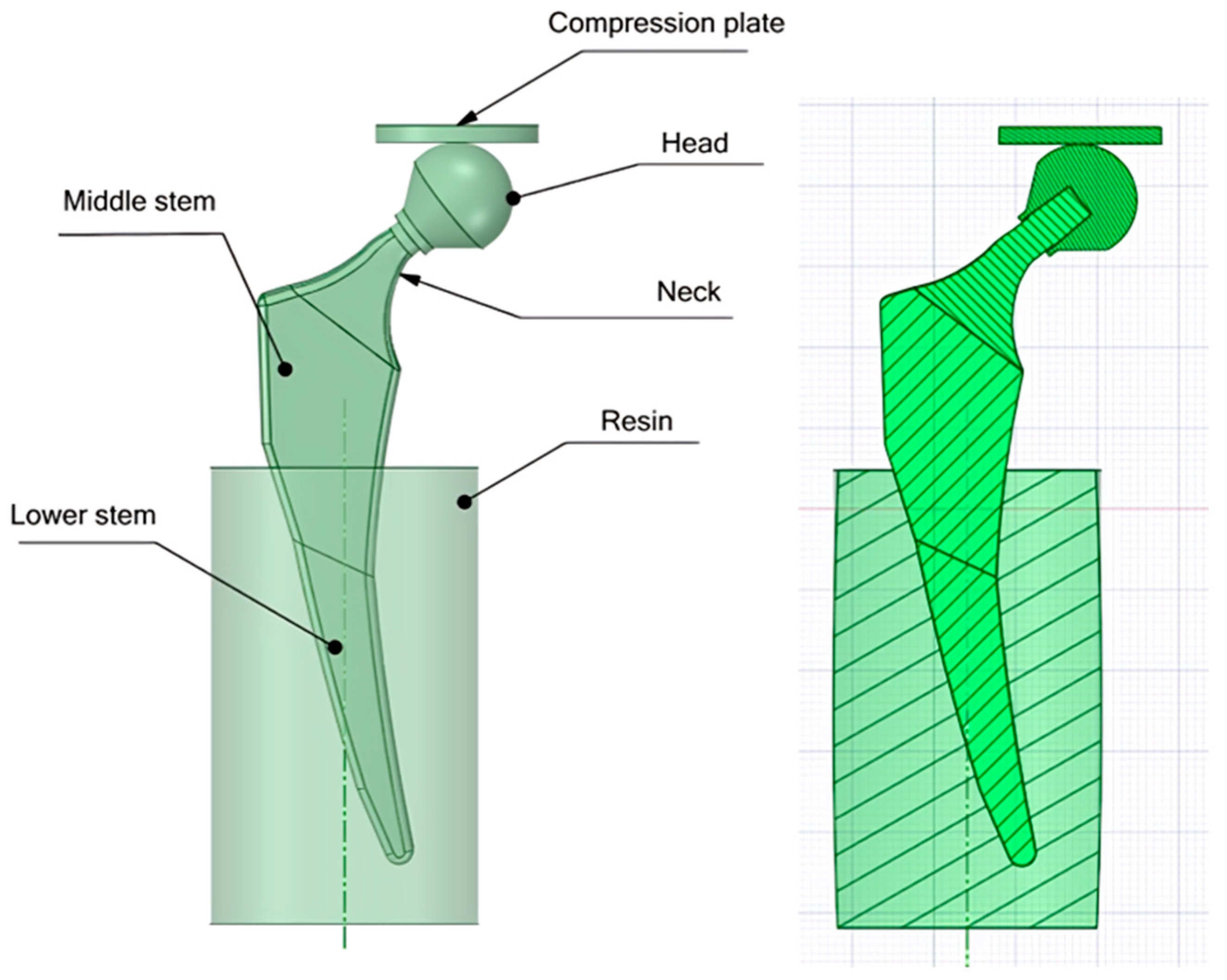
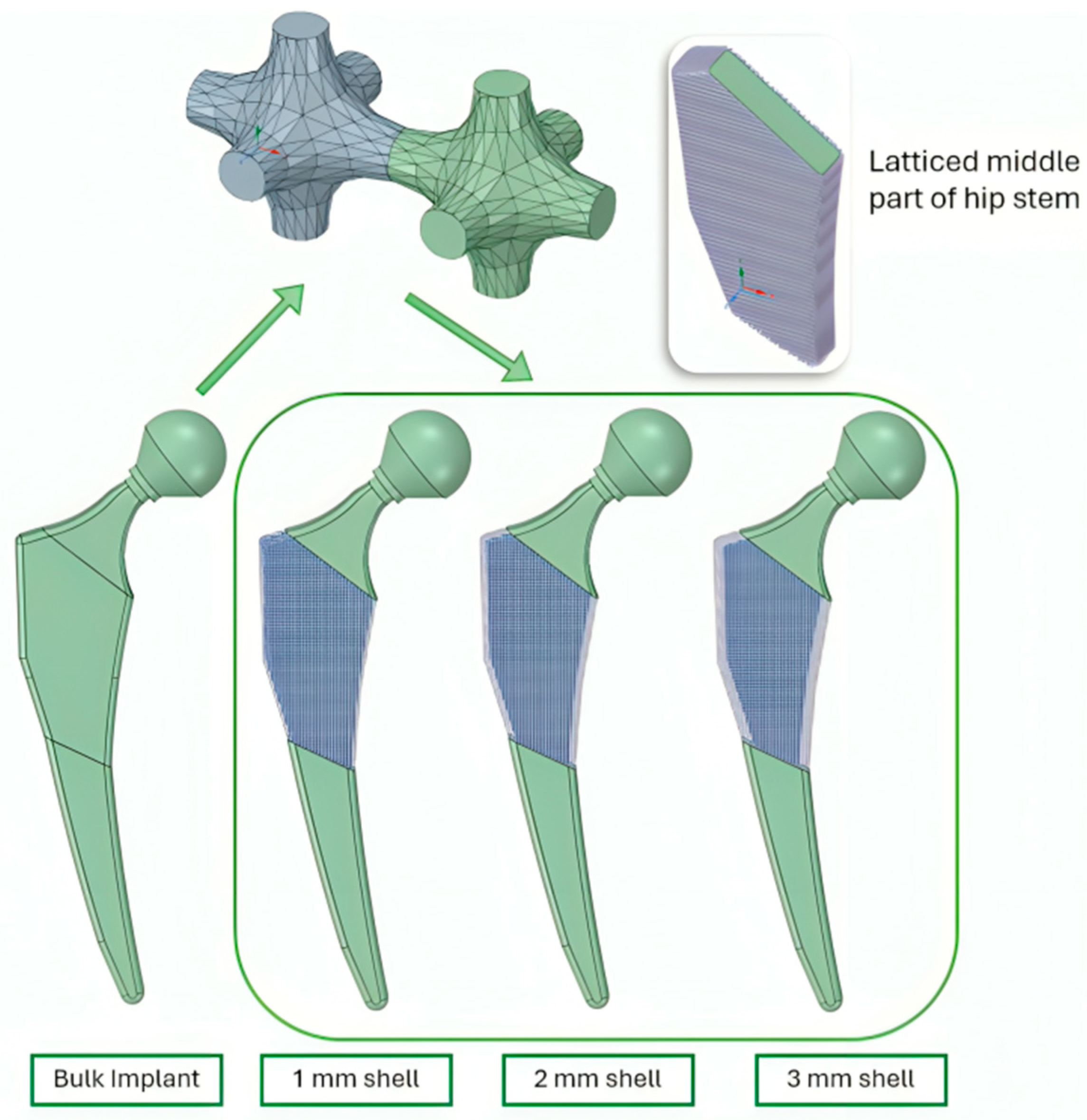
2.2.1. Designing CAD Files

Based on the international standard ASTM F2033-12 [43] of hip implant design, a hip implant was designed using SpaceClaim, ANSYS software version 2020 R2. The traditional standard hip implant comprises three parts: the head, the neck, and the stem. The dimensions of the implant are defined when the head diameter, the neck’s length and diameter, and the length of the intramedullary implant (the stem) are all known [16]. In this study, as shown in Figure 3, the stem was divided into two bodies: the middle stem and the lower stem. This was so we could apply a lattice structure to the middle stem to optimize the design and enhance the bone ingrowth into the holes of the latticed part, thus increasing the fixture of the implant and prolonging the life span of the implant without loosening.
Figure 4 also shows the setup for the compression test following the hip implant testing standard ISO 7206-4:2010 [43], where the compression template compressed the implant and a resin base played the role of the fixed support in the numerical simulation.
Table 4 shows a list of properties of all parts contributing to the numerical simulation of the material.

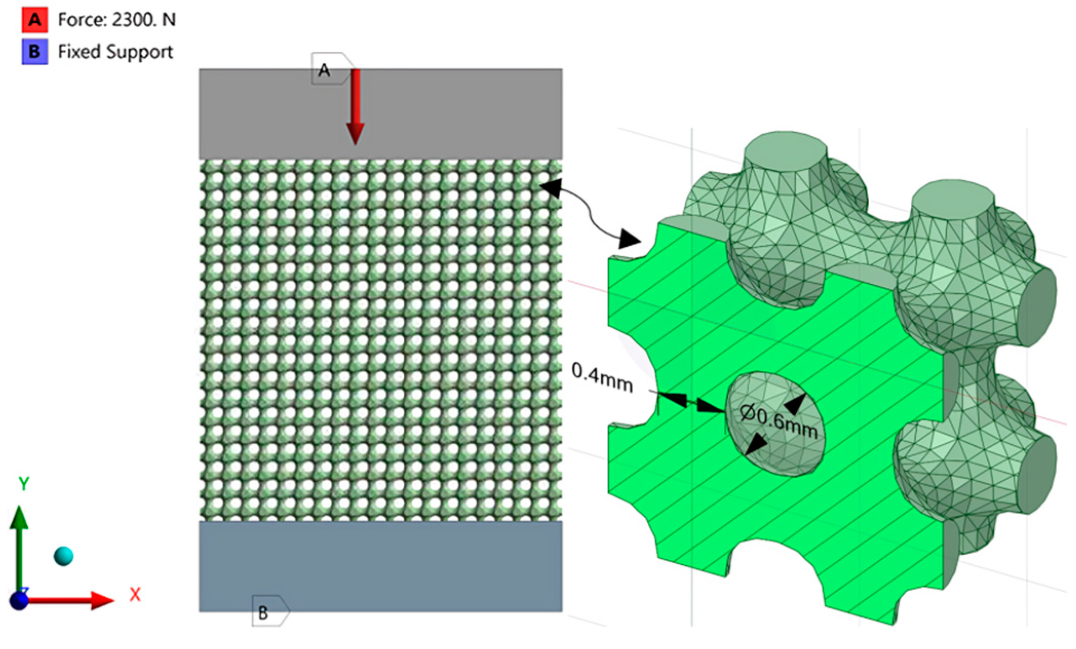
2.2.2. Applying Lattice Structures

Using the SpaceClaim program, the lattice structure of the 3D lattice infill was applied to the middle part of the implant stem. Three variations were used, where a shell of 1, 2, and 3 mm thickness of lattice was applied to the middle stem of the bulk implant. Figure 5 shows the total number of implants to be numerically tested.

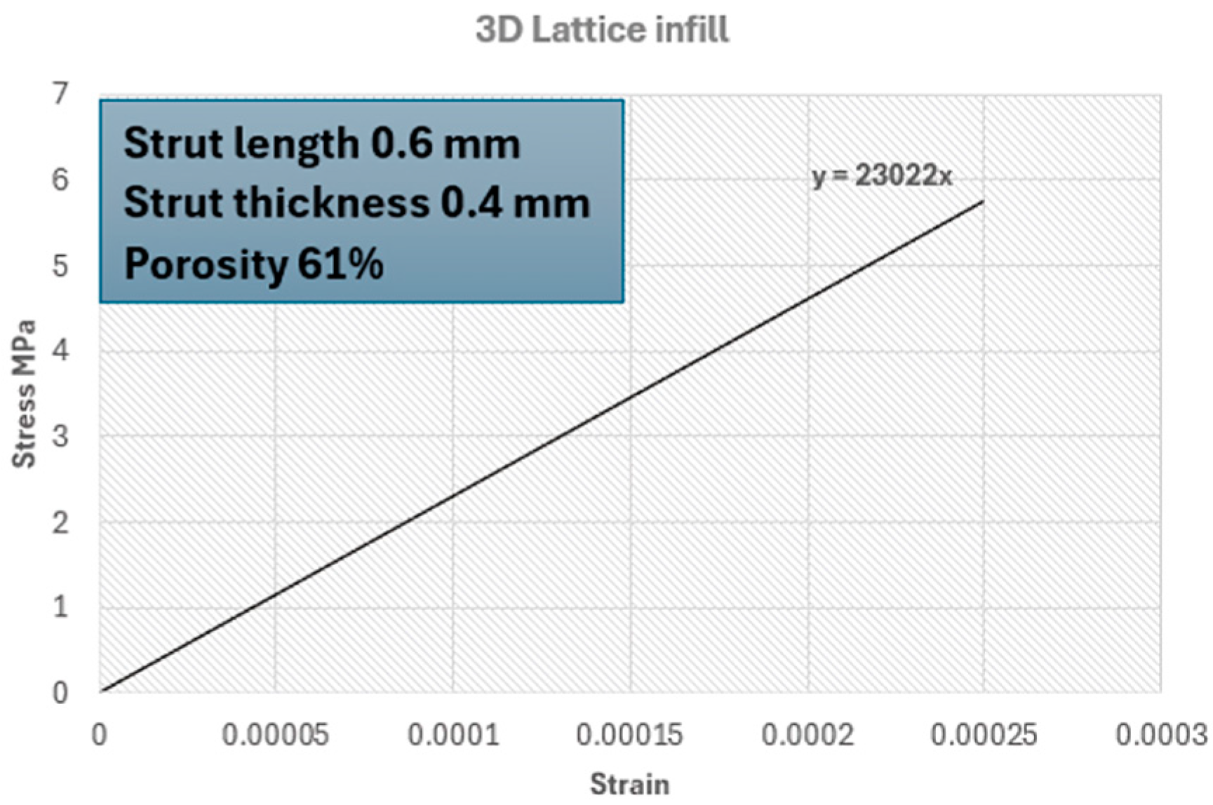
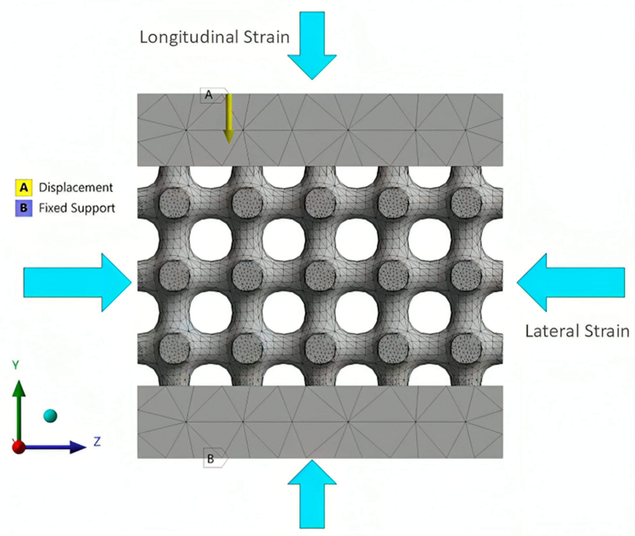
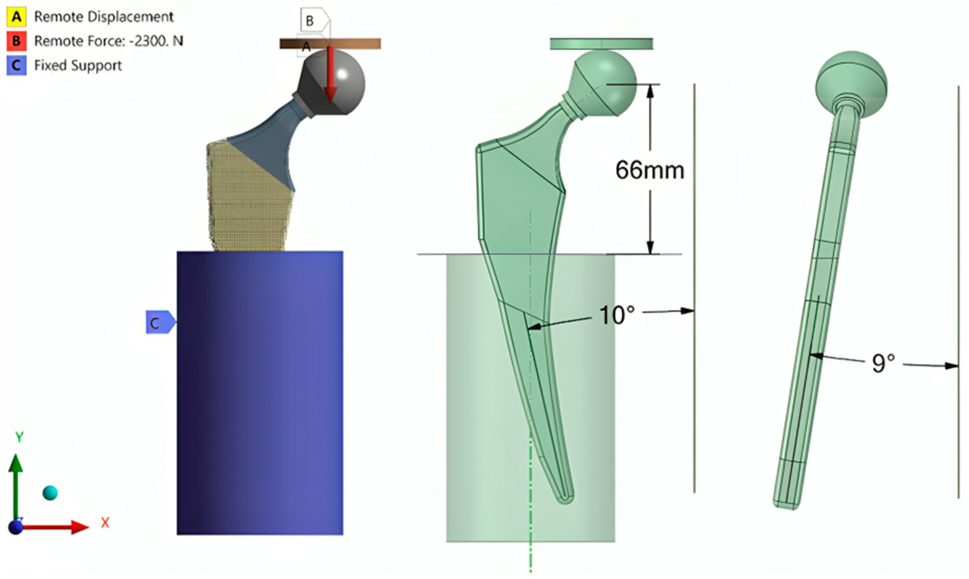
2.2.3. Finite Element Analysis (Latticed Model)

Finite element analysis was performed to simulate the material response of the latticed hip implants under real-life static in vivo conditions. Standard ISO 7206-4:2010 [42] was followed during the compression testing to regulate the conditions regarding the applied force value and angles of the implant and the immersion level of the implant in the resin. The testing setup is introduced in Figure 6. According to the standard, a force of 2300 N was applied to the compression plate. The connection between the compression plate and the head of the implant was set to be frictionless so that the head could slide on the lower surface of the compression plate with no friction.
A displacement restriction was applied to the compression plate to restrict its movement to move freely only on the Y-axis (vertical direction). The resin base was considered a fixed support to the whole setup. The vertical displacement was to be considered the measure of vertical deformation of the implant. A tetrahedral mesh type was used with the model with a patch-independent method. A mesh convergence study was performed using three mesh element sizes of 2 mm, 1 mm, and 0.5 mm. There were 802120, 841846, and 897755 elements for the 1 mm, 2 mm, and 3 mm shell implants, respectively.

2.2.4. Setting the Surrogate Model

In order to save the time and cost of the simulation, the surrogate model was developed where the middle stem of the implants (the latticed part) was modeled as bulk in terms of geometry but with the mechanical properties of the lattice structures. The two main important properties to be inserted into the Mechanical workbench of ANSYS were the Young’s modulus and Poisson’s ratio (Table 2). Figure 7 shows a cross-sectional view of the hip implants to be simulated as surrogate models for the geometrically latticed model.
A comparison in the finite element analysis between the fully latticed models and the surrogate models was performed to show the optimization in processing time.

3. Results

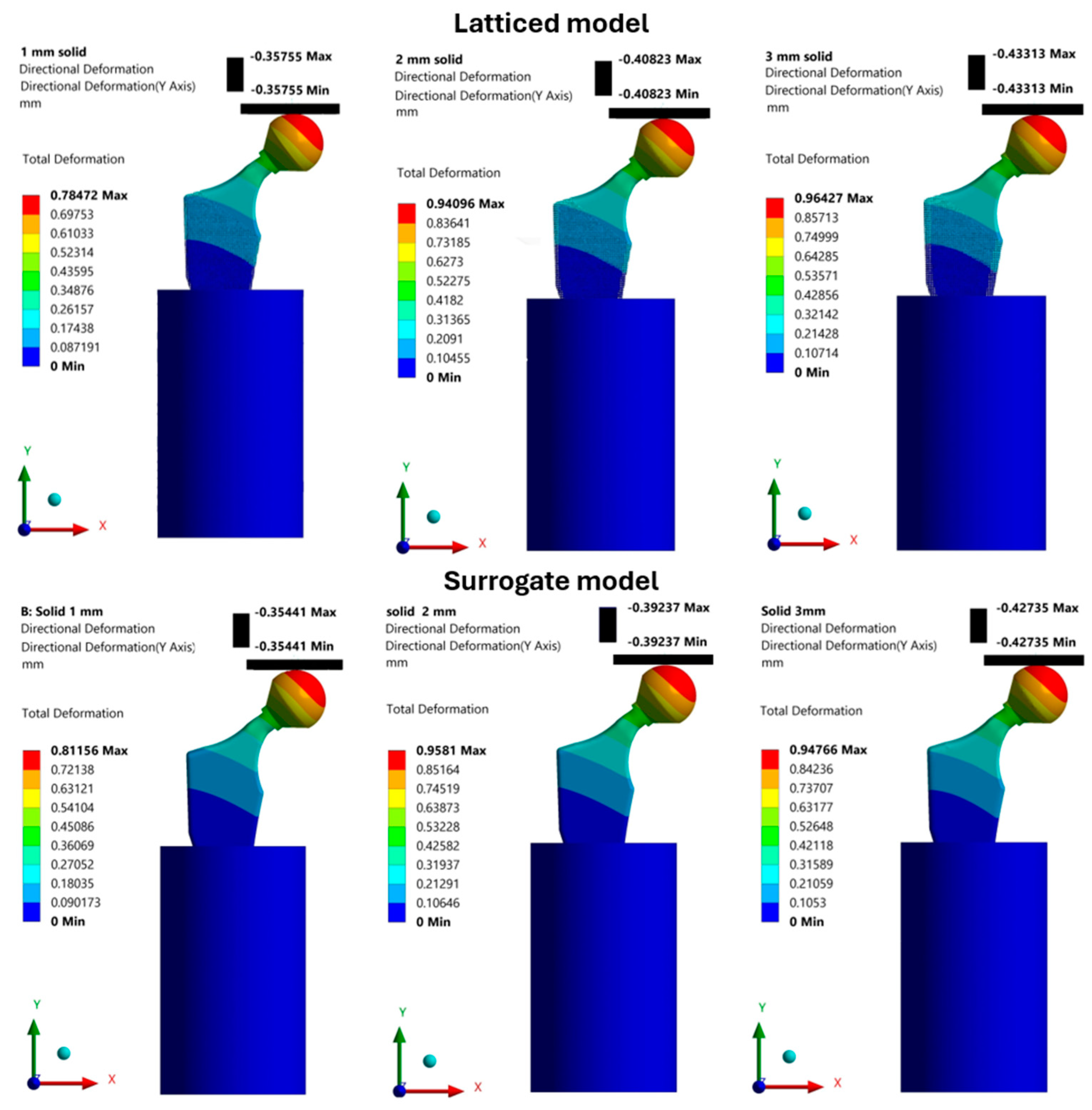
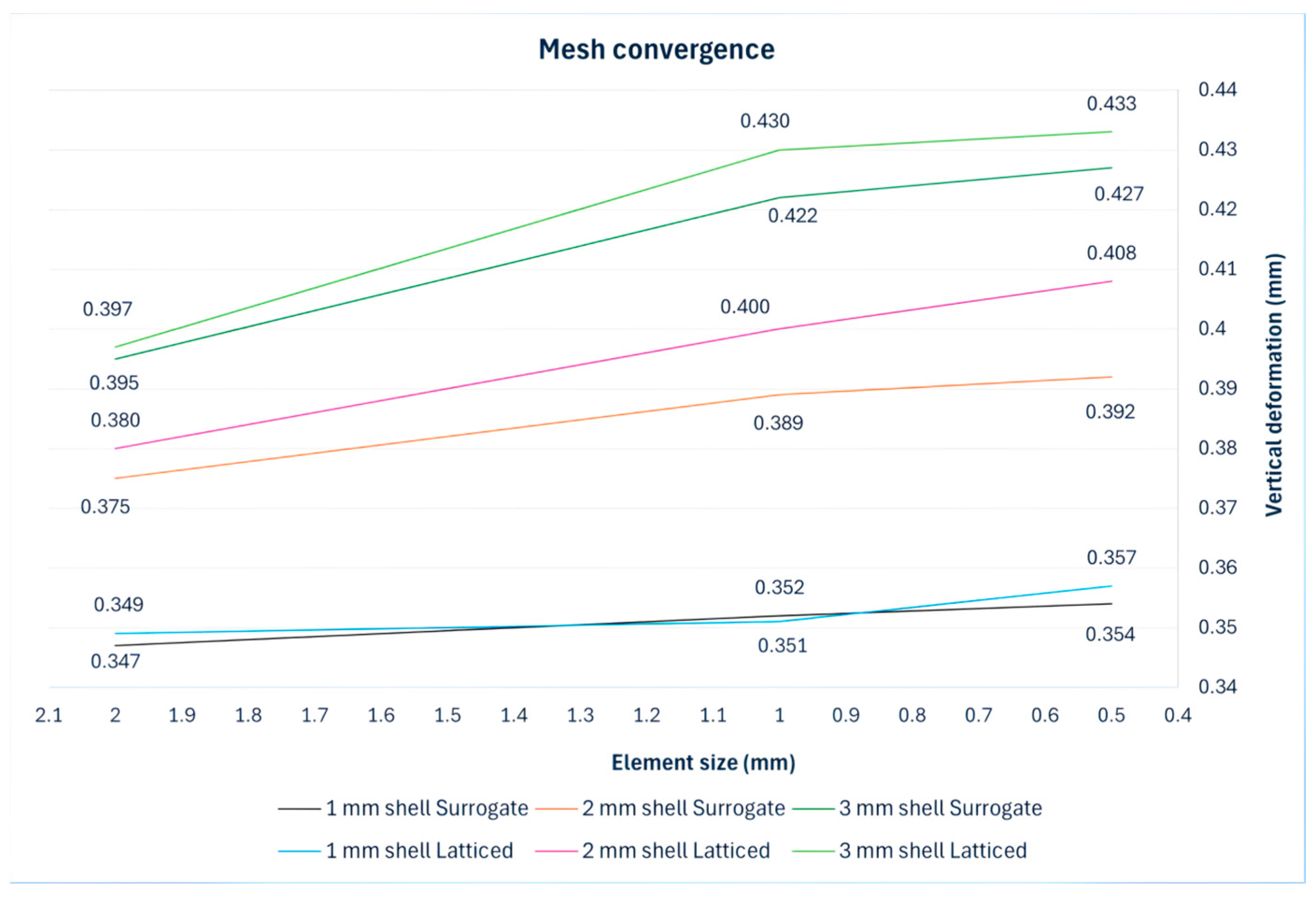
Finite Element Results

Finite element calculations were performed to analyze the compressive behavior of the hip implant using the ANSYS Mechanical workbench 2020 R2 version. The 3D CAD models were examined with FEA in vivo conditions dictated by the standards mentioned previously. Both models, the geometrically latticed and the surrogate model, were analyzed during the FE calculation. Since the compressing machine measured the vertical deformation of its compression plate, Figure 8 compares the two models in terms of the resulting vertical deformation of these plates in the models. The black-colored legends show the vertical deformation of plates as an absolute value (the maximum and minimum values are the same). On the other hand, the colored legend shows the total deformation, which informed the implant’s behavior.
Table 5 numerically compares the accuracy of the difference between using a geometrically latticed model and the surrogate model. The deviation range in the results varied between 1 and 4%, which was within the acceptable range.
The accuracy of the results was inspected using a mesh convergence study based on defining the vertical deformation results against the mesh element size, as shown in Figure 9. A final mesh element size of 0.5 mm with the tetrahedral mesh type and a patch-independent method were set until 5% convergence was reached.
Thus, the surrogate model could be used instead of the geometrically latticed model and gave accurate results under numerical simulations. Table 6 shows a comparison between the two models in terms of solving time and RAM usage in the operating system. The computer used for the simulation had four logical processors with four cores of the type Intel(R), Santa Clara, CA, USA, and the installed physical memory (RAM) was 16 GB.
Using the substitute model drastically reduced time and RAM usage, saving time and simulation costs. The computation time was reduced from thousands to a few seconds and RAM usage was reduced from thousands to a few hundred megabytes.
Figure 10 shows the equivalent stress values for all variations in the lattice-structured implants. As can be seen in the figure, stress values decreased as the shell thickness increased; this was related to the increased deformation in the implants with a shell volume with greater elasticity.

4. Discussion

In this study, the issue of modeling a 3D latticed model of a hip implant was addressed. CAD modeling of 3D latticed hip implants is complicated and always consumes much time and expense related to computing power, which makes simulation studies hard to perform. The authors found that the most effective way is to replace the geometrically latticed model with a bulk model that has the same numerical properties in the simulation software. The main numerical mechanical properties that should be used to define the material in this case are the Young’s modulus and Poisson’s ratio.
In [23], Johannes et al. presented a basis for the selection and practical implementation of surrogate models by using mesh-free surrogate models for structural mechanic FEA simulation. The study suggested that mesh-free surrogate models overcome the drawback that is represented by the need for more computational effort in case a higher-resolution simulation is needed. Lower geometrical complexity could be applied with such models, which would save both the time and cost of the numerical solution. On the other hand, we performed meshed numerical calculations where the solution accuracy was preserved and, yet, the simulation time and computation capacity were reduced.
In our study, the simulation processing of latticed hip implants was optimized by the integration of latticed model’s properties into the bulk model’s properties, which accelerated the solution procedure without having to incorporate a machine learning model to reduce the variables in the process. Aldair et al. [25] tried to combine computational approaches with machine learning-based approaches in order to reduce costs and accelerate design creation.
Using a surrogate model to replace a latticed model depends, however, on many factors. Firstly, the number of variables incorporated into the simulation process—two in this study—can make the process more efficient. Secondly, the computation capacity that is available should be considered; a computer’s RAM memory and processors can define whether the need to reduce a simulation’s load is worthwhile. Lastly, the accuracy level that is needed in the simulation is important; the desired accuracy level can define whether the use of a particular model is suitable or not.

5. Conclusions

In this research, a hip implant was designed in accordance with relevant standards to facilitate numerical simulation. The main goal was to optimize the design by applying lattice structures in three distinct variations to the middle stem area of the hip implant stem. The lattice configuration was implemented as a shell with multiple thicknesses, offering structural flexibility and mechanical efficiency. In order to evaluate the performance of the design variations, numerical compression tests were performed under the established standards for hip implant compression testing.
One good aspect of this research was the introduction of a surrogate model with properties identical to those of the geometrically latticed model. This substitute model helped simplify the complex geometry while preserving the necessary mechanical behavior. The simulation results revealed that the application of lattice structures led to a significant reduction in equivalent stress values, indicating an improvement in the implant’s structural performance. Additionally, the computational time required for the simulation was greatly reduced, leading to considerable cost savings. This reduction in computation time, however, did not affect the accuracy of the results, which remained within an acceptable margin of error (within 5%).
Another benefit to be noticed of using the substitute model was the reduction in RAM usage. Due to the simplification of the simulation process, the model was run efficiently even with a medium-performance computer, thus enhancing accessibility and practicality for research.
For future research, it is planned to validate these numerical findings through laboratory experiments on 3D-printed hip implants. This experimental verification could confirm the reliability of the proposed design optimizations and support the practical implementation of lattice structures in hip implant manufacturing. In general, this study presents a promising approach to the optimization of hip implant design while reducing computational demands and maintaining high accuracy and performance standards.

Author Contributions

Conceptualization, T.M. and R.A.; methodology, T.M.; software, R.A.; validation, T.M. and R.A.; resources, R.A.; writing—original draft preparation, R.A. and T.M.; review and editing, T.M.; visualization, R.A.; supervision, T.M.; project administration, T.M.; funding acquisition, T.M. All authors have read and agreed to the published version of the manuscript.

Funding

This research was supported by the University of Debrecen Scientific Research Bridging Fund (DETKA) and the OMAA 117öu9—Experimentelle und numerische Untersuchung maßgeschneiderter, zel-lulärer Implantate, hergestellt mit AM-Technologie project.

Institutional Review Board Statement

Not applicable.

Informed Consent Statement

Not applicable.

Data Availability Statement

Data is unavailable due to privacy regarding future publication.

Conflicts of Interest

The authors declare no conflicts of interest.

References

  1. Prasad, K.; Bazaka, O.; Chua, M.; Rochford, M.; Fedrick, L.; Spoor, J.; Symes, R.; Tieppo, M.; Collins, C.; Cao, A.; et al. Metallic Biomaterials: Current Challenges and Opportunities. Materials 2017, 10, 884. [Google Scholar] [CrossRef] [PubMed]
  2. Park, J.O.; Bronzino, J.D. Biomaterials; Informa: London, UK, 2002. [Google Scholar] [CrossRef]
  3. Chen, Q.; Thouas, G.A. Metallic implant biomaterials. Mater. Sci. Eng. R Rep. 2015, 87, 1–57. [Google Scholar] [CrossRef]
  4. Capek, J.; Machova, M.; Fousova, M.; Kubásek, J.; Vojtěch, D.; Fojt, J.; Jablonská, E.; Lipov, J.; Ruml, T. Highly porous, low elastic modulus 316L stainless steel scaffold prepared by selective laser melting. Mater. Sci. Eng. C 2016, 69, 631–639. [Google Scholar] [CrossRef]
  5. Kim, H.R.; Jang, S.-H.; Kim, Y.K.; Son, J.S.; Min, B.K.; Kim, K.-H.; Kwon, T.-Y. Microstructures and Mechanical Properties of Co-Cr Dental Alloys Fabricated by Three CAD/CAM-Based Processing Techniques. Materials 2016, 9, 596. [Google Scholar] [CrossRef] [PubMed]
  6. Becker, T.H.; Beck, M.; Scheffer, C. Microstructure and mechanical properties of direct metal laser sintered TI-6AL-4V. S. Afr. J. Ind. Eng. 2015, 26, 1–10. [Google Scholar] [CrossRef]
  7. Bari, K. Design, Simulation, and Mechanical Testing of 3D-Printed Titanium Lattice Structures. J. Compos. Sci. 2023, 7, 32. [Google Scholar] [CrossRef]
  8. Yan, C.; Hao, L.; Hussein, A.; Young, P. Ti–6Al–4V triply periodic minimal surface structures for bone implants fabricated via selective laser melting. J. Mech. Behav. Biomed. Mater. 2015, 51, 61–73. [Google Scholar] [CrossRef]
  9. Huiskes, R.; Weinans, H.; VAN Rietbergen, B. The relationship between stress shielding and bone resorption around total Hip stems and the effects of flexible materials. Clin. Orthop. Relat. Res. 1992, 274, 124–134. [Google Scholar] [CrossRef]
  10. Čapek, J.; Vojtěch, D. Effect of sintering conditions on the microstructural and mechanical characteristics of porous magnesium materials prepared by powder metallurgy. Mater. Sci. Eng. C 2014, 35, 21–28. [Google Scholar] [CrossRef]
  11. Čapek, J.; Vojtěch, D.; Oborná, A. Microstructural and mechanical properties of biodegradable iron foam prepared by powder metallurgy. Mater. Des. 2015, 83, 468–482. [Google Scholar] [CrossRef]
  12. Caravaggi, P.; Liverani, E.; Leardini, A.; Fortunato, A.; Belvedere, C.; Baruffaldi, F.; Fini, M.; Parrilli, A.; Mattioli-Belmonte, M.; Tomesani, L.; et al. CoCr porous scaffolds manufactured via selective laser melting in orthopedics: Topographical, mechanical, and biological characterization. J. Biomed. Mater. Res. B Appl. Biomater. 2019, 107, 2343–2353. [Google Scholar] [CrossRef]
  13. Ryan, G.E.; Pandit, A.S.; Apatsidis, D.P. Porous titanium scaffolds fabricated using a rapid prototyping and powder metallurgy technique. Biomaterials 2008, 29, 3625–3635. [Google Scholar] [CrossRef]
  14. Bosco, R.; Van Den Beucken, J.V.D.; Leeuwenburgh, S.; Jansen, J. Surface Engineering for Bone Implants: A Trend from Passive to Active Surfaces. Coatings 2012, 2, 95–119. [Google Scholar] [CrossRef]
  15. Distefano, F.; Pasta, S.; Epasto, G. Titanium Lattice Structures Produced via Additive Manufacturing for a Bone Scaffold: A Review. J. Funct. Biomater. 2023, 14, 125. [Google Scholar] [CrossRef]
  16. Kladovasilakis, N.; Tsongas, K.; Tzetzis, D. Finite Element Analysis of Orthopedic Hip Implant with Functionally Graded Bioinspired Lattice Structures. Biomimetics 2020, 5, 44. [Google Scholar] [CrossRef]
  17. Nogueira, P.; Lopes, P.; Oliveira, L.; Alves, J.L.; Magrinho, J.P.G.; de Deus, A.M.; Vaz, M.F.; Silva, M.B. Evaluation of Lattice Structures for Medical Implants: A Study on the Mechanical Properties of Various Unit Cell Types. Metals 2024, 14, 780. [Google Scholar] [CrossRef]
  18. Salaha, Z.F.M.; Ammarullah, M.I.; Abdullah, N.N.A.A.; Aziz, A.U.A.; Gan, H.-S.; Abdullah, A.H.; Kadir, M.R.A.; Ramlee, M.H. Biomechanical Effects of the Porous Structure of Gyroid and Voronoi Hip Implants: A Finite Element Analysis Using an Experimentally Validated Model. Materials 2023, 16, 3298. [Google Scholar] [CrossRef]
  19. Chen, W.; Zheng, X.; Liu, S. Finite-Element-Mesh Based Method for Modeling and Optimization of Lattice Structures for Additive Manufacturing. Materials 2018, 11, 2073. [Google Scholar] [CrossRef]
  20. Syam, W.P.; Jianwei, W.; Zhao, B.; Maskery, I.; Elmadih, W.; Leach, R. Design and analysis of strut-based lattice structures for vibration isolation. Precis. Eng. 2018, 52, 494–506. [Google Scholar] [CrossRef]
  21. Cantaboni, F.; Ginestra, P.; Tocci, M.; Colpani, A.; Avanzini, A.; Pola, A.; Ceretti, E. Modelling and FE simulation of 3D printed Co-Cr Lattice Structures for biomedical applications. Procedia CIRP 2022, 110, 372–377. [Google Scholar] [CrossRef]
  22. Paik, J.; Kim, D.; Kim, H.; Kim, H.-S. Numerical analysis of thermal damage by changing irradiation angle for peri-implantitis using photothermal therapy. J. Radiat. Res. Appl. Sci. 2024, 17, 101054. [Google Scholar] [CrossRef]
  23. Hoffer, J.G.; Geiger, B.C.; Ofner, P.; Kern, R. Mesh-Free Surrogate Models for Structural Mechanic FEM Simulation: A Comparative Study of Approaches. Appl. Sci. 2021, 11, 9411. [Google Scholar] [CrossRef]
  24. Suttakul, P.; Vo, D.; Fongsamootr, T.; Wanison, R.; Mona, Y.; Katongtung, T.; Tippayawong, N.; Thawon, I. The role of machine learning for insight into the material behavior of lattices: A surrogate model based on data from finite element simulation. Results Eng. 2024, 23, 102547. [Google Scholar] [CrossRef]
  25. Gongora, A.E.; Friedman, C.; Newton, D.K.; Yee, T.D.; Doorenbos, Z.; Giera, B.; Duoss, E.B.; Han, T.Y.-J.; Sullivan, K.; Rodriguez, J.N. Accelerating the design of lattice structures using machine learning. Sci. Rep. 2024, 14, 13703. [Google Scholar] [CrossRef]
  26. Bai, J.; Li, M.; Shen, J. Prediction of Mechanical Properties of Lattice Structures: An Application of Artificial Neural Networks Algorithms. Materials 2024, 17, 4222. [Google Scholar] [CrossRef]
  27. Liu, C.; Li, S. High-resolution topology optimization method of multi-morphology lattice structures based on three-dimensional convolutional neural networks (3D-CNN). Struct. Multidiscip. Optim. 2023, 66, 235. [Google Scholar] [CrossRef]
  28. Fongsamootr, T.; Suttakul, P.; Tippayawong, N.; Nanakorn, P.; Cappellini, C. Bending behavior of 2D periodic plates with different unit cells: Numerical and experimental investigations. Mater. Today Commun. 2022, 31, 103774. [Google Scholar] [CrossRef]
  29. Kamranfard, M.R.; Darijani, H.; Rokhgireh, H.; Khademzadeh, S. Analysis and optimization of strut-based lattice structures by simplified finite element method. Acta Mech. 2023, 234, 1381–1408. [Google Scholar] [CrossRef]
  30. Müller, P.; Synek, A.; Stauß, T.; Steinnagel, C.; Ehlers, T.; Gembarski, P.C.; Pahr, D.; Lachmayer, R. Development of a density-based topology optimization of homogenized lattice structures for individualized hip endoprostheses and validation using micro-FE. Sci. Rep. 2024, 14, 5719. [Google Scholar] [CrossRef]
  31. Sam, P.; Nanakorn, P.; Theerakittayakorn, K.; Suttakul, P. Closed-form effective elastic constants of frame-like periodic cellular solids by a symbolic object-oriented finite element program. Int. J. Mech. Mater. Des. 2017, 13, 363–383. [Google Scholar] [CrossRef]
  32. Suttakul, P.; Nanakorn, P.; Vo, D. Effective out-of-plane rigidities of 2D lattices with different unit cell topologies. Arch. Appl. Mech. 2019, 89, 1837–1860. [Google Scholar] [CrossRef]
  33. Theerakittayakorn, K.; Nanakorn, P.; Sam, P.; Suttakul, P. Exact forms of effective elastic properties of frame-like periodic cellular solids. Arch. Appl. Mech. 2016, 86, 1465–1482. [Google Scholar] [CrossRef]
  34. Wang, A.-J.; McDowell, D.L. In-Plane Stiffness and Yield Strength of Periodic Metal Honeycombs. J. Eng. Mater. Technol. 2004, 126, 137–156. [Google Scholar] [CrossRef]
  35. Alkentar, R.; File, M.; Mankovits, T. Use of compression test to determine the Young’s modulus of the titanium alloy Ti6Al4V manufactured via direct metal laser sintering. Int. Rev. Appl. Sci. Eng. 2023, 14, 256–262. [Google Scholar] [CrossRef]
  36. Alkentar, R.; Kladovasilakis, N.; Tzetzis, D.; Mankovits, T. Effects of Pore Size Parameters of Titanium Additively Manufactured Lattice Structures on the Osseointegration Process in Orthopedic Applications: A Comprehensive Review. Crystals 2023, 13, 113. [Google Scholar] [CrossRef]
  37. Alkentar, R.; Máté, F.; Mankovits, T. Investigation of the Performance of Ti6Al4V Lattice Structures Designed for Biomedical Implants Using the Finite Element Method. Materials 2022, 15, 6335. [Google Scholar] [CrossRef]
  38. ISO 13314:2011; Mechanical Testing of Metals—Ductility Testing—Compression Test for Porous and Cellular Metals. ISO: Geneva, Switzerland, 2011.
  39. Standard Specification for Titanium and Titanium Alloy Bars and Billets. 2019. Available online: https://store.astm.org/standards/b348 (accessed on 21 March 2025).
  40. U.S Titanium Industry. Titanium Alloys Ti6Al4V. Available online: https://www.azom.com/article.aspx?ArticleID=1547 (accessed on 9 February 2025).
  41. Arabnejad, S.; Johnston, R.B.; Pura, J.A.; Singh, B.; Tanzer, M.; Pasini, D. High-strength porous biomaterials for bone replacement: A strategy to assess the interplay between cell morphology, mechanical properties, bone ingrowth and manufacturing constraints. Acta Biomater. 2016, 30, 345–356. [Google Scholar] [CrossRef]
  42. ISO 7206-4:2010; Partial and Total Hip Joint Prostheses—Part 4: Determination of Endurance Properties and Performance of Stemmed Femoral Components 2010. ISO: Geneva, Switzerland, 2010.
  43. ASTM F2033-12; Standard Specification for Total Hip Joint Prosthesis and Hip Endoprosthesis Bearing Surfaces Made of Metallic, Ceramic, and Polymeric Materials. ASTM International: West Conshohocken, PA, USA, 2012.
Figure 1. Three-dimensional lattice infill specimen’s compression test setup.
Applsci 15 03522 g001
Figure 2. Young’s modulus value of 3D lattice infill type of lattice structures.
Applsci 15 03522 g002
Figure 3. Poisson’s ratio compression test setup.
Applsci 15 03522 g003
Figure 4. Hip implant parts with a cross-section view.
Applsci 15 03522 g004
Figure 5. Applying 3D lattice infill to hip implant.
Applsci 15 03522 g005
Figure 6. Hip implant compression test setup according to ISO 7206-4:2010 standards.
Applsci 15 03522 g006
Figure 7. Cross-sectional view of the hip implants with surrogate models.
Applsci 15 03522 g007
Figure 8. Vertical deformation of compression plates (axis Y) for latticed and surrogate models.
Applsci 15 03522 g008
Figure 9. Mesh convergence study.
Applsci 15 03522 g009
Figure 10. Equivalent stresses in all implant variations.
Applsci 15 03522 g010
Table 1. Chemical composition of Ti64 powder [40].
ElementChemical Composition Percentage%
Al5.50–6.50
V3.50–4.50
O0.13
N0.05
C0.08
H0.012
Fe0.25
Y0.005
Other elements each0.1
Other elements total0.4
Table 2. Material properties of Ti64 used in the finite element simulations [35].
PropertyValueUnit
Elastic modulus106,247MPa
Mass density4.4g/cm3
Poisson’s ratio0.34-
Table 3. Poisson’s ratio compression test results.
Lattice TypeLongitudinal StrainLateral StrainPoisson’s Ratio
3D lattice infill type0.10010.03840.384
Table 4. Properties of the materials used in the finite element simulation.
MaterialYoung’s Modulus MPaPoisson’s RatioApplied to
Ti6Al4V
(Ti64 grade 23)
106,2470.34Hip implant’s parts except for the latticed part
Lattice structure surrogate part
(measured)
23,0220.384Latticed part
CoCrMo220,0000.35Femoral head
316Steel190,0000.26Pressure plate
Resin31000.31Base
Table 5. Deviation in results between geometrically latticed model and the surrogate model.
Model1 mm Lattice2 mm Lattice3 mm Lattice
Vertical Deformation mm
Geometrically latticed model0.3570.4080.433
Surrogate model0.3540.3920.427
Deviation %141
Table 6. Deviation in results between geometrically latticed model and the surrogate model.
1 mm Lattice2 mm Lattice3 mm Lattice
ModelNormal ModelSurrogate ModelNormal ModelSurrogate ModelNormal ModelSurrogate Model
Time (s)158017736320968324
Maximum memory used (MB)187811619241242293140
Disclaimer/Publisher’s Note: The statements, opinions and data contained in all publications are solely those of the individual author(s) and contributor(s) and not of MDPI and/or the editor(s). MDPI and/or the editor(s) disclaim responsibility for any injury to people or property resulting from any ideas, methods, instructions or products referred to in the content.

