Abstract
In the era of Industry 4.0 and the transition toward Industry 5.0, advanced manufacturing is increasingly driven by data analytics, artificial intelligence, and cyber-physical systems. The integration of intelligent monitoring systems and self-learning algorithms is reshaping machining processes, enabling higher efficiency, precision, and sustainability. Recent advancements in smart factories emphasize the use of AI-powered process control, enabling machines to self-optimize, self-correct, and even self-retrain to maintain optimal performance. This paper proposes a hybrid control and monitoring framework designed to enhance turning operations by integrating artificial neural networks (ANNs) for predictive modeling and adaptive recalibration. The system leverages machine learning (ML) to improve machining efficiency, tool longevity, and energy consumption optimization. By implementing forward and inverse ANN models, the framework enables real-time estimation of cutting forces and energy consumption, facilitating data-driven decision-making in machining processes. Furthermore, an adaptive recalibration mechanism ensures continuous model updates, allowing the system to dynamically adjust based on evolving machining conditions such as tool wear, material properties, and environmental variations. This research contributes to these advancements by proposing an ANN-based hybrid approach, predictive modeling, and adaptive recalibration. The proposed framework ensures continuous monitoring, automated adjustments, and intelligent decision-making, making it a scalable and adaptable solution for modern machining operations.
1. Introduction
Turning operations play a fundamental role in machining processes within the manufacturing industry, and their integration with Industry 4.0 and 5.0 is essential for achieving digital transformation. As smart manufacturing evolves, real-time data acquisition, predictive analytics, and AI-driven process optimization are becoming critical for enhancing efficiency, reducing downtime, and improving sustainability.
Implementing digital solutions in turning operations enables adaptive control, intelligent monitoring, and automated recalibration, ensuring precision and energy-efficient machining.
Deep learning-based models, reinforcement learning strategies, and hybrid AI-driven control systems are being actively developed to enhance real-time decision-making and process automation.
Artificial neural networks (ANNs) are highly effective machine learning algorithms that are inspired by the human brain’s functionality and complex structure. ANNs consist of interconnected neurons, which allows them to transmit and process information with great efficiency [1].
The continuous evolution of ANNs in manufacturing is driven by their ability to model complex, nonlinear relationships between machining parameters, offering superior predictive accuracy compared to conventional analytical models. Current research is expanding towards physics-informed neural networks (PINNs), transfer learning, and federated learning, enabling models to leverage prior knowledge, generalize across different machining setups, and collaboratively improve across distributed systems [2]. These developments contribute to the creation of self-adaptive, highly efficient, and autonomous manufacturing systems, aligning with the future vision of sustainable and intelligent production ecosystems.
The prediction of cutting forces in metal cutting processes relies on physical principles and can be categorized into two main approaches: analytical models and numerical simulations using finite element analysis. With advancements in artificial intelligence and machine learning, various algorithms have been developed to enhance the accuracy and efficiency of force prediction [3].
Also, surface roughness prediction is crucial for improving the surface integrity of machined parts to reduce energy and frictional losses; at the same time, minimizing cutting force and tool wear would contribute to a cost-effective and environmentally friendly machining environment [4].
The most important criteria on the basis of which the optimal cutting regimes are determined are the criterion of maximum productivity or minimum processing time and the criterion of minimum processing cost. When determining the cutting regimes based on these criteria, the problem of the efficiency with which the machine tool works and the consumption of energy for cutting is not often raised. The lack of knowledge of the connection between the working parameters of the machine tool, as well as the effects of the operation of the machine tools at the highest possible efficiency on the specific consumption of electrical energy and the productivity of cutting constitute an explanation for this problem.
Studies have consistently shown that cutting parameters such as cutting speed, feed rate, and the depth of cut significantly influence power and energy consumption. For instance, higher cutting speeds generally increase power consumption due to greater mechanical work and heat generation [5]. The geometry of the cutting tool, including the diameter, number of flutes, and material, influences energy usage. Tools with improved shape can lower cutting forces and thus energy consumption [6]. Empirical models based on experimental data have been widely used to predict power and energy consumption in milling. These models often relate cutting parameters to energy use through regression analysis [5]. Mechanical models focus on the physics of the cutting process, considering torque, forces, and power at the tool–workpiece interface. Several studies have focused on optimizing cutting parameters to minimize energy consumption while maintaining product quality. Techniques such as response surface methodology, Taguchi methods, and genetic algorithms have been employed for this purpose [7]. Optimizing the tool path can reduce unnecessary movements and idle time, leading to lower energy consumption. Minimum quantity lubrication and dry machining have been used to reduce energy compared to traditional flood cooling [8]. The development of energy-efficient machine tools, including those with regenerative braking, variable speed drives, and energy recovery systems, has been a focus of many studies. These technologies can significantly reduce the overall energy footprint of machining operations [9].
The yield of a processing system is its main characteristic, and it is influenced by a series of factors such as frictional losses, work speed, the quality of surfaces in relative motion, and the quality of the lubrication of elements in relative motion. Energy tests for a technological system can be completed based on cutting force or braking force. Equipment that generates braking force or momentum with friction or electricity does not allow for the direct determination of the braking force in the processing area.
Yuzhong and Yusuf [10] proposed a spindle-bearing and machine tool system consisting of a rotating shaft, tool holder, angular contact ball bearings, and machine tool mounting. The model anticipates bearing stiffness, mode shapes, and frequency response function, as well as static and dynamic deflections along the cutter and spindle shaft.
Yanfang at al. [11] provide a method for calculating the ideal bearing preload across a broad range of speeds. It takes into account both thermally induced bearing preload and initial preload synthetically, and it is validated through simulations and experiments. The fatigue life determines the maximum bearing preload, the approach is suited to machine tool spindle usage, and a bearing temperature rise of more than 30 °C is rare within the usual speed range. In order to completely comprehend the characteristics of additional load losses, Shuyun et Hebing [12] provides a model for additional load losses based on the power flow model, under the assumption that the spindle motor’s slip is minor. Additionally, a test system is created to measure the machine tool’s input power, spindle speed, and cutting torque to determine the additional load losses. A first-order polynomial can suit the experimental findings obtained from the CNC lathe, which indicate that the additional load losses coefficient varies with spindle speed and cutting torque. To experimentally validate the proposed method for determining the variable preload, the stiffness of the spindle and the temperature rise of the test bearing are measured [13]. The results indicate that the variable preload spindle performs exceptionally well, exhibiting a lower temperature rise at high speeds compared to the constant pressure preload spindle and a significant increase in dynamic stiffness at low speeds.
The research progress in machining processes reflects a shift towards intelligent, data-driven approaches (e.g., ANNs and PINNs) that enhance prediction accuracy and efficiency for cutting forces, surface roughness, and energy consumption. Cutting force prediction has transitioned from physics-based analytical and FEA methods to data-driven ML approaches, offering improved accuracy, efficiency, and adaptability. ML has demonstrated remarkable potential in handling complex machining scenarios and enabling real-time applications. However, challenges such as data dependency, limited real-time capability, a lack of interpretability, and poor generalizability persist. Innovations in optimization, tool design, and machine tool technology further support sustainable manufacturing.
Despite significant progress, several shortcomings persist, including insufficient emphasis on energy efficiency, limited data generalization, challenges in real-time applicability, inadequate model interpretability, and barriers to industrial integration. Other critical gaps include the lack of standardized validation protocols, computational complexity for practical deployment, and incomplete multi-objective optimization frameworks that balance cutting force, surface quality, and energy use. Addressing these challenges requires comprehensive and diverse datasets, hybrid modeling approaches that combine physical insights with data-driven techniques, standardized benchmarking for consistent evaluation, and industry-focused solutions to enhance scalability and adoption. Overcoming these hurdles will be essential to fully harnessing the potential of machine learning and related advancements in intelligent, sustainable manufacturing ecosystems.
The primary research objective of this study about a hybrid control and monitoring framework for turning operations using artificial neural networks is to develop a robust system that enhances real-time decision-making and machining efficiency. Specifically, this study aims to design an inverse ANN model for accurate real-time cutting force prediction using electrical parameters, enabling dynamic optimization and tool protection. It also seeks to construct a forward ANN model to predict and optimize energy consumption based on cutting force and machining parameters, promoting sustainable operations. Additionally, the research will explore implementing an adaptive recalibration mechanism that leverages incremental learning, transfer learning, and full retraining to maintain model accuracy amidst changing conditions. Furthermore, the framework will initiate a dynamic model management system for the efficient storage and selection of trained models, ensuring adaptability across diverse turning scenarios. Finally, the study will evaluate the framework’s integration with Industry 4.0/5.0 principles, assessing its impact on machining performance, energy efficiency, and tool life within intelligent manufacturing ecosystems.
The methods adopted include data-driven modeling, employing forward and inverse ANN models trained using structured and stratified datasets. These datasets were systematically collected through controlled experiments that simulate various loading conditions by applying calibrated braking forces at different spindle speeds, thus enabling the measurement and correlation of machining parameters such as cutting force, power consumption, and current intensity.
2. Materials and Methods
2.1. The Framework for Turning Operations Using Artificial Neural Networks
This document presents the iterative development of a hybrid control and monitoring framework for turning operations using artificial neural networks. The goal of this framework is to support real-time decision-making, optimizing machining parameters for efficiency, energy savings, and tool protection—Figure 1.
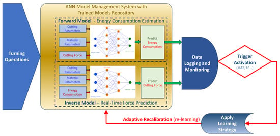
Figure 1.
ANN Model Management System.
The framework is structured around three key objectives:
- Real-time force prediction: The inverse ANN model estimates the cutting force (F) based on electrical parameters such as current (I) and power (P). This enables real-time monitoring of machining conditions, helping to prevent excessive tool wear and optimize cutting parameters dynamically.
- Energy consumption estimation: The forward ANN model predicts energy consumption based on cutting force and machining parameters. This facilitates real-time efficiency assessment and enables the optimization of power usage in machining operations.
- Adaptive recalibration: The system incorporates an adaptive recalibration mechanism that detects deviations in model accuracy due to changing machining conditions, such as tool wear, material variations, or process drift. This is achieved through continuous data acquisition, monitoring, and an intelligent trigger mechanism that activates recalibration when error metrics (e.g., MAE and R2) exceed predefined thresholds.
To maintain accuracy under varying conditions, the recalibration system supports:
- Incremental learning—fine-tuning the model with new data while retaining existing knowledge.
- Transfer learning—adapting pre-trained models to new machining scenarios.
- Full retraining—rebuilding models using updated datasets for significant changes in machining conditions.
The Model Management System includes a repository of trained models, dynamically storing and selecting models based on real-time machining conditions. The recalibration trigger mechanism can operate on either fixed thresholds or an adaptive approach that continuously assesses when recalibration is necessary, either in real time or at periodic intervals.
The framework integrates the ability to predict cutting forces in real time using an inverse ANN model that enables dynamic adjustments to machining parameters. Simultaneously, the forward ANN model estimates energy consumption, allowing for real-time optimization of power usage, thus integrating monitoring with actionable control for enhanced efficiency. The adaptive recalibration mechanism further supports this hybrid approach by continuously monitoring prediction accuracy (via error metrics like MAE and R2) and triggering model updates (through incremental learning, transfer learning, or full retraining) to maintain performance under varying conditions such as tool wear or material changes.
This framework aligns with Industry 4.0 and 5.0 principles, integrating continuous sensor data acquisition, intelligent data logging, and automated recalibration through machine learning-based strategies. By implementing dynamic model selection and self-learning capabilities, the system ensures optimal machining performance, reduced energy consumption, and enhanced tool life.
2.2. Experimental Setup
A typical complete lathe working process includes machine start-up, standby, spindle start-up, no-load operation, cutting material, no-load operation, spindle stop, standby, and machine shut down [14]. The most predominant part is taken by no-load operation and cutting material times (Figure 2). Therefore, in our dataset we will consider and train our models with values from these 2 cases: no-load operation with different spindle speeds with force F = 0 and cutting material with specific load force F corresponding to a specific spindle speed n.
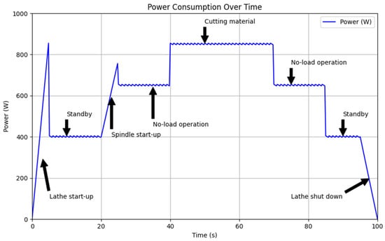
Figure 2.
A complete CNC lathe working process.
To validate the proposed artificial neural network framework for hybrid control and monitoring in turning operations, an experimental dataset was acquired under controlled conditions. Instead of cutting a specific material, a custom braking device was employed to apply variable force loads to the spindle while operating at different spindle speeds. This setup effectively simulated cutting force variations, allowing for a systematic analysis of energy consumption patterns under different machining conditions.
For each experimental run, a predefined force, as a result of a radial force R [daN], was applied to the spindle at a specified speed n [rpm] and was measured with non-contact Digital Tachometer code 9221-999A. Corresponding electrical parameters, including power consumption P [kW] and current I [A], were recorded. This approach ensured that the dataset captured a diverse range of force–load interactions, making it representative of real-world cutting conditions while maintaining a controlled and repeatable testing environment.
The experimental tests were conducted in the laboratories of the National University of Science and Technology Politehnica Bucharest. The tests were carried out with a universal lathe. The SNA 500 × 1500 normal lathe is a medium-sized machine tool manufactured by Uzina de Strunguri Arad with a maximum machining diameter over guides of 500 mm, and the power for driving the main movement is 10 kW. Other characteristics that can be mentioned are the number of main spindle speed steps: 24; the speed range: 16–1600 rpm; the voltage: 380 V; the control voltage: 110 V; and the main fuse: 35 A. The loading of the main shaft of the machine tool was carried out with the help of a custom braking device [15] which behaves as a dynamometric device that allows the application of a radial force R [daN] that causes the appearance of a tangential force F [daN] in the contact area between the loading element and a test specimen on the main shaft of the machine tool.
The research was carried out under the following conditions: the outer diameter of the test piece (233 mm) was clamped in the main shaft of the machine tool and external stress with three-way radial force was applied simultaneously using a worm gear. During the experiments, no liquid was used to reduce the temperature. Through symmetrical distribution, the load on the main shaft of the machine tool was uniform, thus avoiding the occurrence of vibrations, according to Figure 3.
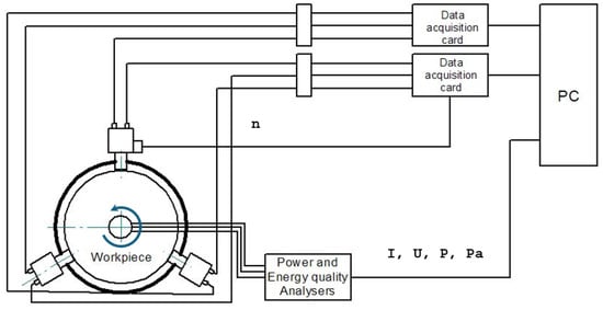
Figure 3.
Experimental data acquisition scheme.
The measurement was based mainly on three sensors, each being in contact with the test piece fixed in the lathe device. Each sensor consists of body 2, attached through plate 1. The application of force, on the test piece, is carried out through body 5, fixed in the channel of disc 4. The deformations of the elastic element in the radial (loading) and tangential (braking) directions are determined, respectively, and attached to the body through the supports 7 and 9. To reduce the vibrations, each sensor is provided with a damping element, fixed between sleeve 3 and an elastic element. The total radial and tangential force are equal to the sum of the corresponding component forces and , respectively.
The loading device (Figure 4) is mounted on the guides of the machine tool. It consists of three identical dynamometers that can move simultaneously in the radial direction using a worm-wheel gear. The elastic element of each sensor allows deformation in two directions. The deviations in the radial and tangential directions are measured using inductive comparators using the INSIZE 2134-10 Digital Indicator (provided by INSIZE Co., Suzhou, China). Using calibration constants, these deviations are converted into force in the radial and tangential directions that is equivalent to the main cutting force component.
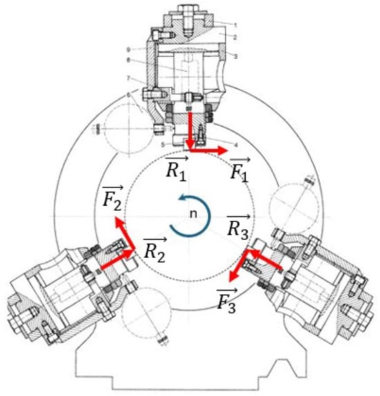
Figure 4.
Braking device with radial forces distribution.
The determinations were made for different workloads on the main shaft and were obtained by varying the speed and the braking force. The electrical and power parameters (voltage, U, intensity, I, active power, P, apparent power, Pa, power factor, cos φ, and yield η) of the lathe drive motor were measured using the Fluke 1738 Three-Phase Power Quality Loggers (provided by Fluke Corporation, Everett, United States of America) [16]. The coefficient of friction was not taken into account, radial force was applied, and each tangential component was read; then, the values were summed and the force was listed in the table for that combination. Based on the experimental program outlined in Table 1, power parameters, including power P and current I, were measured for various spindle speeds ranging from 16 rpm to 1600 rpm, with applied loading forces varying between 0 and 290 daN. For cases where F = 0, the system operated under no-load conditions at the corresponding spindle speed, serving as a reference for unloaded power consumption. Measurements indicated that the current intensity I varied between 4.3 A, recorded at a spindle speed of 100 rpm and a force load of 12.262 daN, and reached a maximum of 11.33 A at 125 rpm under a significantly higher force load of 275.45 daN. Similarly, active power P exhibited variations ranging from a minimum of 0.96 kW at 20 rpm with a load of 69.5 daN to a peak value of 5.72 kW recorded at 630 rpm with a load of 86.358 daN. These measurements clearly illustrate the correlation between spindle speed, load force, and the corresponding electrical parameters, establishing a solid foundation for further modeling and analysis. Table 1 presents a representative subset of the measurements, illustrating key data points from the full experimental dataset.

Table 1.
The dependent and independent variables of the process parameters.
2.3. Structured Data Preprocessing for ANN: Splitting, Stratification, and Preparation
The ANN system comprises forward and inverse models, trained to predict energy consumption and cutting forces, respectively. The framework evolved through multiple stages of optimization, improving predictive accuracy and adaptability to real-world machining conditions. The software models were developed in Python 3.8.10, ensuring compatibility with other solutions using JSON and CSV formats for data exchange and interaction.
Forward and inverse modeling (bidirectional learning) was applied to predict machining parameters by training two complementary neural network models: the forward model, which estimates electrical parameters such as current I and power P based on input machining conditions like force F and spindle speed n, and the inverse model, which determines the required force F needed to achieve specific electrical responses, enabling the adaptive recalibration and optimization of machining processes.
The dataset preprocessing starts with reading the raw data from a CSV/JSON file and introducing an auxiliary check (“F_zero_flag”) to indicate instances where the applied force (F [daN]) is zero. This flag is essential for ensuring stratified sampling, maintaining a proportional distribution of zero-force cases across all subsets. To begin partitioning, 15% of the data is allocated for testing, while the remaining 85% is reserved for training and validation. The stratification ensures that the dataset remains balanced, preventing any subset from being biased towards specific operating conditions.
The next step was splitting the 85% of remaining data into training (70%) and validation (15%) sets, ensuring a final 70/15/15 split across training, validation, and test sets. This separation allows the model to be trained effectively while using the validation set for hyperparameter tuning and early stopping, preventing overfitting.
Finally, the processed data were saved into separate CSV/JSON files for training, validation, and testing. The structured partitioning ensures that the model can generalize well across different operational conditions while maintaining data integrity. This method effectively prevents data leakage and allows for robust model evaluation, ensuring that performance metrics reflect real-world applicability.
3. Results
3.1. ANN Model Configuration
The goal of this stage was to systematically refine the ANN model, enhancing its predictive accuracy, computational efficiency, and stability while optimizing key architectural and training parameters for improved generalization. In turning operations, a large variety of ANN models were used based on different learning algorithms, architectures, activation functions and statistical metrics [4].
The development of the ANN model followed a structured and iterative approach, progressing through several stages of refinement to optimize its predictive accuracy and computational efficiency. The evolution of the model can be outlined in four distinct models, each introducing refinements to enhance performance and stability. The main models’ characteristics and attributes are presented in Table 2.
Initially, the first implementation model_v01 established a baseline model using the Keras API 2.13.1 from TensorFlow 2.13.0 [17]. The model was structured as a simple multilayer perceptron (MLP) [18,19] with an input layer of two neurons corresponding to the machining parameters—cutting force F [daN] and spindle speed [rpm]—and an output layer predicting electrical characteristics—current I [A] and power P [kW]. Between these layers, the network incorporated two hidden layers with neurons, employing ReLU activation functions [20] to introduce non-linearity. The Adam optimizer [21] was selected for backpropagation, with mean squared error (MSE) as the loss function.
Recognizing the need for improved convergence and more effective weight adjustments, the next iteration, model_v02, replaced the standard gradient-based optimizer with resilient backpropagation (RProp) [22]. This algorithm adapts the learning rate for each parameter independently, adjusting weight updates based on previous gradient signs rather than absolute values, thus mitigating issues related to vanishing or exploding gradients. This modification led to a more stable training process with better convergence behavior, particularly when processing machining data with varying numerical scales.

Table 2.
ANN models’ characteristics and attributes.
Table 2.
ANN models’ characteristics and attributes.
| Attribute | model_v01 | model_v02 | model_v03 | model_v04 |
|---|---|---|---|---|
| API Used | TensorFlow/Keras | PyTorch [21] | PyTorch | PyTorch |
| Network Type | (MLP) | (MLP) | (MLP) | (MLP) |
| Model Architecture | 2->7->13->2 | 2->32->23->2 | 2->25->10->2 | 2->28->18->2 |
| Activation Function | ReLU | Sigmoid | LeakyReLU | LeakyReLU |
| Loss Function | (MSE) | (MSE) | (MSE) | Weighted MSE alpha = 2.55 beta = 1 |
| Optimizer | Adam (lr = 0.001) | RProp (lr = 0.01) | Adam (lr = 0.001) | Adam |
| Batch Processing | Batch size = 8 | Whole batch | Mini batch (size = 8) | Yes, batch size = 8 |
| Early Stopping | Not implemented | No | Yes, patience = 90 | Yes, patience = 5000 |
Further refinements in the third iteration, model_v03, addressed potential activation saturation issues by incorporating LeakyReLU as the activation function. Unlike standard ReLU, which can cause neurons to become inactive for negative inputs, LeakyReLU maintains small negative outputs, ensuring that gradients continue to flow through the network. This change allowed for better information propagation during training, reducing the likelihood of dead neurons and improving generalization capabilities.
The final iteration, model_v04, introduced a weighted loss function to differentially prioritize errors in predicting current I [A] and power P [kW]. Since machining processes have varying sensitivities to these parameters, assigning distinct penalties in the loss calculation ensured that the network maintained balanced predictive performance across both outputs. This was achieved by defining a custom weighted MSE loss function, where a weighting factor was applied to the error in predicting and another factor too.
The main performance metrics of the four models are presented in Table 3.

Table 3.
Performance metrics of the models.
Another step was to identify algorithms and solutions for fine-tuning model parameters suitable for current models [23]. The model parameters were fine-tuned using Bayesian optimization, dynamically selecting optimal hyperparameters such as learning rate, hidden layer sizes, and loss weights.
An additional optimization script was developed utilizing Optuna [24], which systematically optimizes the key hyperparameters based on the parameters and their specified ranges provided in Table 4.

Table 4.
Hyperparameters used for Bayesian optimization.
Each iteration in this development pathway contributed to progressively improving model accuracy and robustness. The incorporation of advanced activation functions, adaptive optimizers, and custom loss formulations demonstrates a systematic refinement process tailored to the specific characteristics of machining data. These enhancements collectively led to superior predictive capabilities, setting the stage for effective deployment in real-time monitoring and adaptive control scenarios.
3.2. Optimized Forward Model Training
Based on the optimization of hyperparameters using Optuna 4.2.1, the forward model developed was trained following a structured neural network architecture with an input layer of two neurons, two hidden layers with 21 and 43 neurons, respectively, and an output layer with two neurons, forming a 2→21→43→2 configuration, as shown in Figure 5.
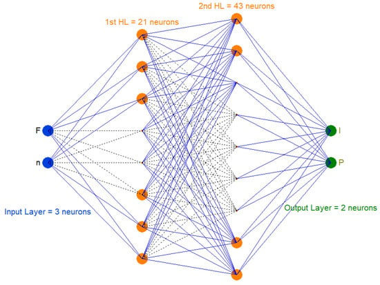
Figure 5.
Forward model architecture.
This optimized forward model architecture was implemented using PyTorch 2.4.1, leveraging NumPy [25] for numerical computations and Scikit-learn [26] for preprocessing tasks such as data normalization. Forward model attributes and metrics are shown in Table 5.

Table 5.
Forward model attributes and metrics.
The forward model employed a weighted mean squared error (WMSE) loss function, which assigns different levels of importance to the predicted values of current I [A] and power P [kW], ensuring a balanced optimization process, with specific weight parameters alpha = 2.5 and beta = 1.0. Training was conducted using the Adam optimizer, with an adaptive learning rate set to 0.006602635824190219, refined through Bayesian optimization for improved convergence. The model was trained over 5000 epochs with a batch size of 32, incorporating an early stopping patience threshold of 5000 epochs to prevent overfitting. The best validation loss achieved was 0.0106977075338364, while the weighted MSE on scaled data was 0.0354. Performance metrics indicate high accuracy, with a mean absolute error (MAE) of 0.0873290076851845 A for current I and 0.0312103275209665 kW for power P. Additionally, the coefficient of determination (R2) for the current prediction was 0.9911, and for power prediction, it was 0.9980, demonstrating strong predictive capabilities and a highly optimized neural network model (Figure 6).
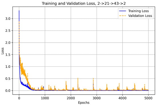
Figure 6.
Forward model training and validation loss for 2->21->43->2.
3.3. Optimized Inverse Model Training
The purpose was to train a model to estimate cutting force F [daN] based on measured electrical parameters I [A], P [kW], and spindle speed n [rpm].
Using the same mature model architecture developed for the forward model, the inverse model (Figure 7) is structured as a fully connected neural network with an input layer consisting of three neurons, two hidden layers with 13 and 23 neurons, respectively, and a single-output neuron, forming the 3→13→23→1 architecture.
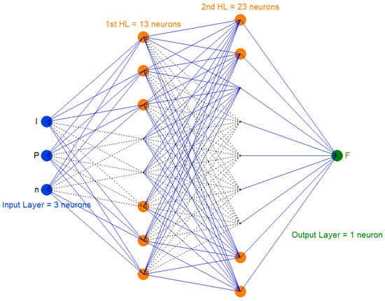
Figure 7.
Inverse model architecture.
This design was implemented using PyTorch, with NumPy for numerical operations and Scikit-learn for data preprocessing, particularly for feature scaling. This model was trained to predict the cutting force (F) [daN] based on input features, which included current I [A], power P [kW], and spindle speed n [rpm].
The weighted mean squared error (WMSE) serves as the loss function, ensuring accurate force estimation while balancing the prediction error across different scales of input data. The training process employs the Adam optimizer with a learning rate of 0.001, maintaining stability in weight updates over 5000 epochs, with an early stopping patience threshold of 5000 epochs to prevent overfitting. The model was trained using a batch size of eight, allowing efficient weight updates and improved generalization according to Table 6.

Table 6.
Inverse model attributes and metrics.
The best validation loss achieved was 0.001419, while the weighted MSE on scaled data was 0.002964, highlighting the model’s precision. The mean absolute error (MAE) for force prediction was 3.6986 daN, reflecting a low deviation from actual values. Furthermore, the model demonstrates high reliability, as indicated by an R2 score of 0.997541, which signifies a strong correlation between the predicted and actual cutting force values. This optimized inverse model effectively enables real-time estimation of cutting force, contributing to adaptive machining control strategies (Figure 8).
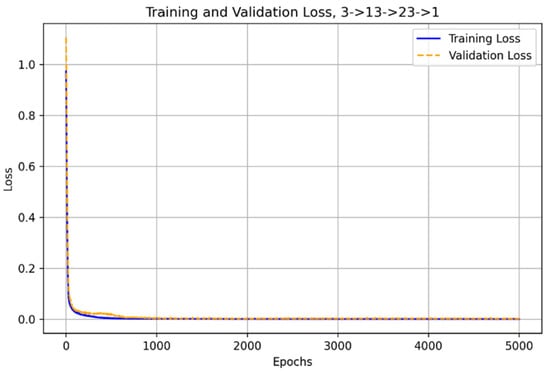
Figure 8.
Inverse model training and validation loss for 3->13->23->1.
4. Discussion
Inference Models and Results
The inference model is the trained neural network that takes input machining parameters, such as force F [daN] and spindle speed n [rpm] and predicts output values like current I [A] and power P [kW] (forward model) or estimates the required force based on a given current, power, and spindle speed (inverse model). It may enable real-time predictions using the learned relationships from training data, allowing for adaptive control and monitoring in machining operations.
The inference codes for both models, forward and inverse, were designed to load a trained feedforward neural network model for forward/inverse prediction in a machining process. The codes developed perform the following key tasks:
- Model selection—This automatically selects the best-trained model based on validation loss. It scans the “models” directory for the best-trained model, identifies files following the given forward/inverse pattern, and selects the model with the lowest validation.
- Data preprocessing—This loads input data from JSON input file and applies feature scaling.
- Inference execution—This uses the trained model to generate predictions.
- Error monitoring and trend analysis—This maintains an inference log to detect model drift by saving all runs with parameters.
- Performance evaluation—This computes the MAE, weighted MSE, and R2 scores. It continuously evaluates whether model performance degrades over time by comparing recent predictions to expected trends.
- Logging and display—This saves the inference log for trend monitoring and displays predictions.
The forward model takes F [daN] and spindle speed n [rpm] as inputs and predicts electrical parameters I [A] and P [kW], as shown in Figure 9.
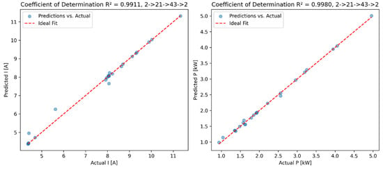
Figure 9.
Coefficient of determination for I [A] and P [kW].
High R2 scores (0.9911 for I [A] and 0.9980 for P [kW]) indicate that the coefficient of determination (R2) values are very close to one, indicating that the model explains almost all of the variability in the data. This suggests that the model captures the underlying relationships between inputs (force, F, and rotational speed, n) and outputs (current and power) with high fidelity.
For inverse model loads, the optimal inverse model reads the input JSON containing measured I [A], P [kW], and n [rpm], and uses the trained model to predict the corresponding cutting force F [daN], as shown in Figure 10.
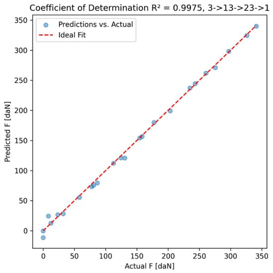
Figure 10.
Coefficient of determination for F [daN].
The high R2 score (0.997541 for F [daN] indicates that the coefficient of determination (R2) is very close to one, which means that the model explains nearly all of the variability in the target variable F, confirming strong predictive capabilities.
The current inference implementation incorporates periodic monitoring of prediction accuracy to detect deviations. Inference scripts continuously track errors over time by calculating mean absolute error (MAE) and the coefficient of determination for ongoing validation. If performance degrades beyond a predefined threshold, such as when MAE exceeds 0.2 or drops below 0.9, the system flags the need for recalibration.
The developed inference models have already incorporated a foundational mechanism to support adaptive recalibration through continuous performance monitoring. Specifically, the inference code integrates a routine for calculating critical performance metrics, such as mean absolute error (MAE) and the coefficient of determination (R2), during operational use. If performance degrades beyond a predefined threshold, such as when MAE exceeds 0.2 or drops below 0.9, the system flags the need for recalibration. These metrics serve as predefined trigger conditions, enabling the automatic detection of deviations in predictive performance. Consequently, when monitored values fall outside acceptable thresholds (e.g., MAE exceeding a specified limit or R2 dropping below a set standard), the system flags the necessity for recalibration or re-learning. This integrated monitoring approach establishes the initial framework necessary for implementing more sophisticated adaptive learning strategies, such as incremental retraining or transfer learning, thus ensuring the models remain accurate and reliable under evolving machining conditions.
Moving forward, the model could be further improved by exploring alternative architectures, hyperparameter tuning, or incorporating additional features that might enhance performance in more complex scenarios.
Although the models perform well under known conditions, adaptive recalibration requires the ability to adjust predictions dynamically in response to variations in machining parameters. Next, developments should take into account changes in material properties, such as differences in hardness or cutting resistance which can impact force and power consumption, altering the expected outputs. Additionally, tool wear can lead to gradual deviations in the machining process, influencing the forces applied and energy consumption [14]. Environmental factors and process variations introduce further unpredictability, requiring a system capable of adapting to these evolving conditions.
To achieve true adaptive recalibration, several enhancements could be implemented. Automated data collection and model retraining would ensure that real-time machining data are continuously logged and analyzed. If actual measured values deviate significantly from model predictions, an automated process could be triggered to retrain the network with the updated dataset, incorporating new machining conditions. Incremental learning could also be employed instead of full retraining, where model weights are fine-tuned using recent data rather than reconstructing the model from scratch. Transfer learning techniques could further enhance adaptability by adjusting a pre-trained model without discarding previously learned knowledge.
The infrastructure for continuous data logging, performance evaluation, and trigger-based recalibration decisions has been outlined clearly, yet real-time integration with edge computing or embedded industrial systems has not been fully operationalized.
Real machining power includes losses (friction and motor inefficiencies) beyond the ideal P = F·v relationship, as seen in Table 1 (e.g., P = 1.62 kW at 16 rpm, F = 12.262 daN vs. 4.69 kW at 630 rpm, F = 47.123 daN). The ANN’s inverse model, using P, current (I), and n, captures these nonlinearities, achieving high accuracy (R2 = 0.997541, MAE = 3.6986 daN). Current provides additional electrical insights, while the braking device setup (Section 2.2) introduces system-specific effects the ANN adapts to. Unlike a static calculation, the ANN’s recalibration (Section 2.1) handles dynamic changes, making it more robust for real-time Industry 4.0/5.0 applications.
In this study, cutting forces (F) are labeled as independent variables (Table 1), yet in actual turning, forces depend on user-set parameters like the depth of cut (αp) and feed rate (f), not direct control. This presented experimental design from Section 2.2 employs a braking device to simulate forces (F: 0–290 daN) at varying spindle speeds (n: 16–1600 rpm) rather than actual material removal. Here, F and n serve as proxies for cutting conditions, with P and I measured as outcomes (Table 1), bypassing the direct use of αp and f. This controlled approach isolates force–speed–energy relationships, yielding high predictive accuracy (R2 > 0.99), but limits direct mapping to real cutting parameters. Future work aims to incorporate αp, f, and vc via expanded experiments, enhancing applicability to industrial turning scenarios.
The ANN’s architecture and training process enable it to model the nonlinear interactions between F, n, P, and I effectively within the given dataset. Its high accuracy confirms it “understands” these relationships. However, the absence of variables like real cutting parameters means it does not capture the full spectrum of influences and interactions in actual turning, limiting its practical scope.
Expanding the experiment to a factorial DOE—incorporating additional factors—would generate a richer dataset, enabling the ANN to “understand” the process holistically and yield more robust, generalizable results.
The current forward and inverse ANN models successfully predict machining parameters with high accuracy, demonstrating their suitability for adaptive recalibration. However, to fully realize the objective of a self-adaptive system, further enhancements are needed to enable the automatic detection of process drift and real-time model adjustments. By integrating continuous monitoring, incremental learning, and dynamic model selection, the system can evolve towards a fully adaptive recalibration framework, ensuring robust and optimized performance even as machining conditions change over time.
5. Conclusions
The scientific justification of this research lies in the necessity of enhancing precision, adaptability, and efficiency in turning operations within modern manufacturing systems.
This framework establishes a foundation for intelligent machining process optimization, paving the way for autonomous manufacturing systems driven by AI-based decision-making. By integrating artificial neural networks (ANNs) with adaptive learning strategies, the proposed approach enhances both predictive accuracy and system adaptability in turning operations.
The key achievements of this research include the following:
- The development of a robust ANN-based hybrid control and monitoring framework that integrates forward and inverse modeling for machining process optimization.
- High predictive accuracy achieved through Bayesian optimization and weighted loss functions, ensuring precise estimations of energy consumption and cutting forces.
- The implementation of adaptive recalibration strategies, allowing models to dynamically adjust based on real-time performance monitoring.
This work opens the path for future advancements in the following:
- Real-time deployment: Implementing the trained models on edge computing systems for real-time monitoring and control.
- Online adaptive learning: Enabling continuous learning and self-tuning models to dynamically adjust parameters in response to evolving machining conditions.
- Expanded input parameters: Integrating additional machining features such as vibration, temperature, and acoustic signals to enhance predictive accuracy.
To further enhance system robustness and long-term adaptability, a hybrid modeling approach is proposed, combining physical principles with neural networks to achieve both stability and flexibility. The key elements of this approach include the following:
- Baseline physical/theoretical model: Leveraging well-established machining equations and empirical relationships to provide a stable foundation.
- Neural network for real-time corrections: Employing ANN-based models to dynamically adjust and compensate for deviations caused by factors like tool wear, material inconsistencies, and environmental changes.
This “physics-informed neural network” (PINN) or “knowledge-based + machine learning” strategy may ensure higher stability, generalization, and long-term adaptability, outperforming purely data-driven models that require frequent, full retraining.
By integrating cyber-physical systems, AI, and machine learning, this framework contributes to the evolution of smart manufacturing in Industry 4.0 and 5.0, enabling manufacturers to optimize production, extend tool life, and enhance system resilience in data-driven machining environments.
Author Contributions
Conceptualization, B.F.A. and V.G.; methodology, B.F.A.; software, B.F.A.; validation, B.F.A.; formal analysis, B.F.A. and V.G.; investigation, B.F.A. and V.G.; resources, B.F.A. and V.G.; data curation, B.F.A. and V.G.; writing—original draft preparation, B.F.A. and V.G.; writing—review and editing, B.F.A. and V.G.; visualization, B.F.A. and V.G.; supervision, B.F.A.; project administration, B.F.A. All authors have read and agreed to the published version of the manuscript.
Funding
This research was funded by the National University of Science and Technology POLITEHNICA Bucharest.
Institutional Review Board Statement
Not applicable.
Data Availability Statement
The original contributions presented in the study are included in the article, further inquiries can be directed to the corresponding author.
Acknowledgments
The authors wish to express their gratitude to POLITEHNICA Bucharest for providing support through access to infrastructure.
Conflicts of Interest
The authors declare no conflicts of interest. The funders had no role in the design of the study; in the collection, analyses, or interpretation of data; in the writing of the manuscript; or in the decision to publish the results.
References
- Djurovic, S.; Lazarevic, D.; Cirkovic, B.; Mišic, M.; Ivkovic, M.; Stojcetovic, B.; Petkovic, M.; Ašonja, A. Modeling and Prediction of Surface Roughness in Hybrid Manufacturing–Milling after FDM Using Artificial Neural Networks. Appl. Sci. 2024, 14, 5980. [Google Scholar] [CrossRef]
- Sajadi, P.; Rahmani Dehaghani, M.; Tang, Y.; Wang, G.G. Physics-Informed Online Learning for Temperature Prediction in Metal AM. Materials 2024, 17, 3306. [Google Scholar] [CrossRef] [PubMed]
- Liu, M.; Xie, H.; Pan, W.; Ding, S.; Li, G. Prediction of Cutting Force via Machine Learning: State of the Art, Challenges and Potentials. J. Intell. Manuf. 2025, 36, 703–764. [Google Scholar] [CrossRef]
- Chakraborty, S.; Chakraborty, S. Applications of Artificial Neural Networks in Machining Processes: A Comprehensive Review. Int. J. Interact. Des. Manuf. 2024, 18, 1917–1948. [Google Scholar] [CrossRef]
- Kara, S.; Li, W. Unit Process Energy Consumption Models for Material Removal Processes. CIRP Annals 2011, 60, 37–40. [Google Scholar] [CrossRef]
- Campatelli, G.; Lorenzini, L.; Scippa, A. Optimization of Process Parameters using a Response Surface Method for Minimizing Power Consumption in the Milling of Carbon Steel. J. Clean. Prod. 2014, 66, 309–316. [Google Scholar] [CrossRef]
- Rajemi, M.F.; Mativenga, P.; Aramcharoen, A. Sustainable Machining: Selection of Optimum Turning Conditions based on Minimum Energy Considerations. J. Clean. Prod. 2010, 18, 1059–1065. [Google Scholar] [CrossRef]
- Sharma, S.V.; Dogra, M.; Suri, N.M. Cooling Techniques for Improved Productivity in Turning. Int. J. Mach. Tools Manuf. 2016, 49, 435–453. [Google Scholar] [CrossRef]
- Denkena, B.; Abele, E.; Brecher, C.; Dittrich, M.A.; Kara, S.; Mori, M. Energy-efficient Machine Tools. CIRP Ann.—Manuf. Technol. 2020, 69, 646–667. [Google Scholar] [CrossRef]
- Yuzhong, C.; Yusuf, A. Modeling of Spindle-Bearing and Machine Tool Systems for Virtual Simulation of Milling Operations. Int. J. Mach. Tools Manuf. 2007, 47, 1342–1350. [Google Scholar]
- Yanfang, D.; Zude, Z.; Mingyao, L. Bearing Preload Optimization for Machine Tool Spindle by the Influencing Multiple Parameters on the Bearing Performance. Adv. Mech. Eng. 2017, 9, 1–9. [Google Scholar]
- Shuyun, J.; Hebing, M. Investigation of Variable Optimum Preload for a Machine Tool Spindle. Int. J. Mach. Tools Manuf. 2010, 50, 19–28. [Google Scholar]
- Hu, S.; Fei, L.; Yan, H.; Bin, P. Characteristics of Additional Load Losses of Spindle System of Machine Tools. J. Adv. Mech. Des. Syst. Manuf. 2010, 4, 1221–1233. [Google Scholar] [CrossRef]
- Zhao, G.; Zhao, Y.; Meng, F.; Guo, Q.; Zheng, G. Prediction Model of Machine Tool Energy Consumption in Hard-to-Process Materials Turning. Int. J. Adv. Manuf. Technol. 2020, 106, 4499–4508. [Google Scholar] [CrossRef]
- Gheorghiță, C. Research on the Energy Parameters of Machining Processes and Systems. Ph.D. Thesis, Politehnica University Bucharest, Faculty of Technological Systems Engineering and Management, Manufacturing Engineering Department, Bucharest, Romania, 1998. [Google Scholar]
- Available online: https://www.fluke.com/en/product/electrical-testing/power-quality/1736-1738 (accessed on 3 March 2025).
- TensorFlow Developers. TensorFlow, v2.18.0; Zenodo: Online, 2024. [Google Scholar]
- Haykin, S. Neural Networks: A Comprehensive Foundation, 2nd ed.; Prentice Hall: New Jersey, NJ, USA, 1999. [Google Scholar]
- Spanu, P.; Abaza, B.F.; Constantinescu, T.C. Analysis and Prediction of Temperature Using an Artificial Neural Network Model for Milling Glass Fiber Reinforced Polymer Composites. Polymers 2024, 16, 3283. [Google Scholar] [CrossRef]
- Agarap, A.F. Deep Learning using Rectified Linear Units (relu). arXiv 2018, arXiv:1803.08375. [Google Scholar]
- Kingma, D.P.; Ba, J. Adam: A Method for Stochastic Optimization DP Kingma. arXiv 2014, arXiv:1412.6980. [Google Scholar]
- Riedmiller, M.; Braun, H. A Direct Adaptive Method for Faster Backpropagation Learning: The Rprop Algorithm. Proc. Int. Jt. Conf. Neural Netw. 1993, 1, 586–591. [Google Scholar]
- Dijmărescu, M.R.; Abaza, B.F.; Voiculescu, I.; Dijmărescu, M.C.; Ciocan, I. Surface Roughness Analysis and Prediction with an Artificial Neural Network Model for Dry Milling of Co–Cr Biomedical Alloys. Materials 2021, 14, 6361. [Google Scholar] [CrossRef]
- Takuya, A.; Shotaro, S.; Toshihiko, Y.; Takeru, O.; Masanori, K. Optuna: A Next-generation Hyperparameter Optimization Framework. In Proceedings of the KDD’19: Proceedings of the 25th ACM SIGKDD International Conference on Knowledge Discovery & Data Mining, Anchorage, AK, USA, 4–8 August 2019. [Google Scholar]
- Harris, C.R.; Millman, K.J.; van der Walt, S.J.; Gommers, R.; Virtanen, P.; Cournapeau, D.; Wieser, E.; Taylor, J.; Berg, S.; Smith, N.J.; et al. Array Programming with NumPy. Nature 2020, 585, 357–362. [Google Scholar] [CrossRef]
- Pedregosa, F.; Varoquaux, G.; Gramfort, A.; Michel, V.; Thirion, B.; Grisel, O.; Blondel, M.; Prettenhofer, P.; Weiss, R.; Dubourg, V.; et al. Scikit-learn: Machine Learning in Python. J. Mach. Learn. Res. 2011, 12, 2825–2830. [Google Scholar]
Disclaimer/Publisher’s Note: The statements, opinions and data contained in all publications are solely those of the individual author(s) and contributor(s) and not of MDPI and/or the editor(s). MDPI and/or the editor(s) disclaim responsibility for any injury to people or property resulting from any ideas, methods, instructions or products referred to in the content. |
© 2025 by the authors. Licensee MDPI, Basel, Switzerland. This article is an open access article distributed under the terms and conditions of the Creative Commons Attribution (CC BY) license (https://creativecommons.org/licenses/by/4.0/).