3.1. Characteristics of Axial Force Changes and Workpiece Deformation Mechanism During Drilling of Thin-Walled Plates of AF1410 High-Tensile Steel
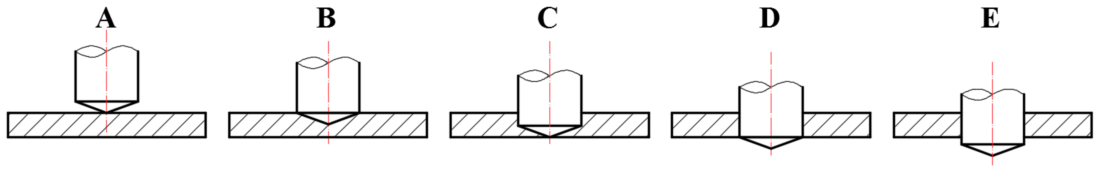
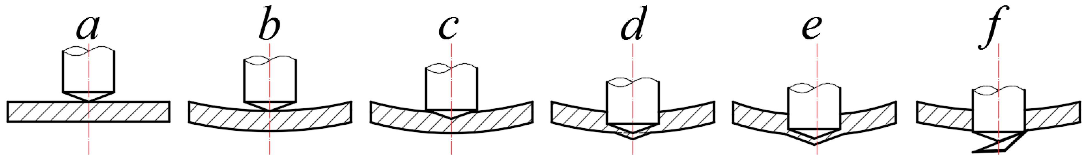
When the thickness of the workpiece is greater than the height of the drill tip, the drilling process can be divided into several characteristic stages as shown in
Figure 2 if the deformation of the thin-walled plate during the drilling process is not considered. In the figure, A is the top edge of the drill just touching the upper surface of the workpiece, B is the intersection point of the main and secondary cutting edges of the drill drilling to the upper surface of the workpiece, C is the top edge of the drill drilling to the bottom surface of the workpiece, D is the intersection point of the main and secondary cutting edges of the drill drilling to the bottom surface of the workpiece, and E is the point at which the drill drills out the bottom surface of the workpiece completely, and the axial force is zero. If the friction between the drill bit and the hole wall is not taken into account, the axial force is theoretically 0 when the drill bit is in the position of the D point.
If the deformation of the workpiece in the drilling process is not considered, the axial traveling of the drill from state A to state B is the height of the drill tip; the axial traveling from state B to state C is the difference between the thickness of the workpiece and the height of the drill tip; the axial traveling from state C to state D is the height of the drill tip. The theoretical drilling time for each characteristic stage of the drilling process is calculated as follows:
where
hi is the theoretical stroke of the drill at a certain stage, in mm;
f is the feed, in mm/r;
n is the spindle speed, in r/min; and Δ
ti is the theoretical drilling time, in
s.
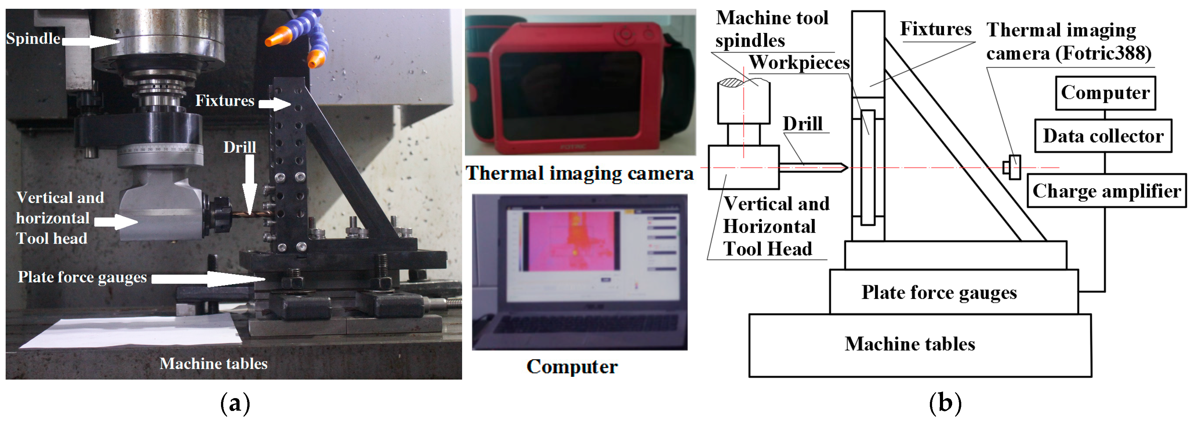
Drilling experiments were carried out on the center of a thin-walled plate of AF1410 high-tensile steel under the cutting speed
v = 25.1 m/min (rotational speed
n = 1000 r/min), feed
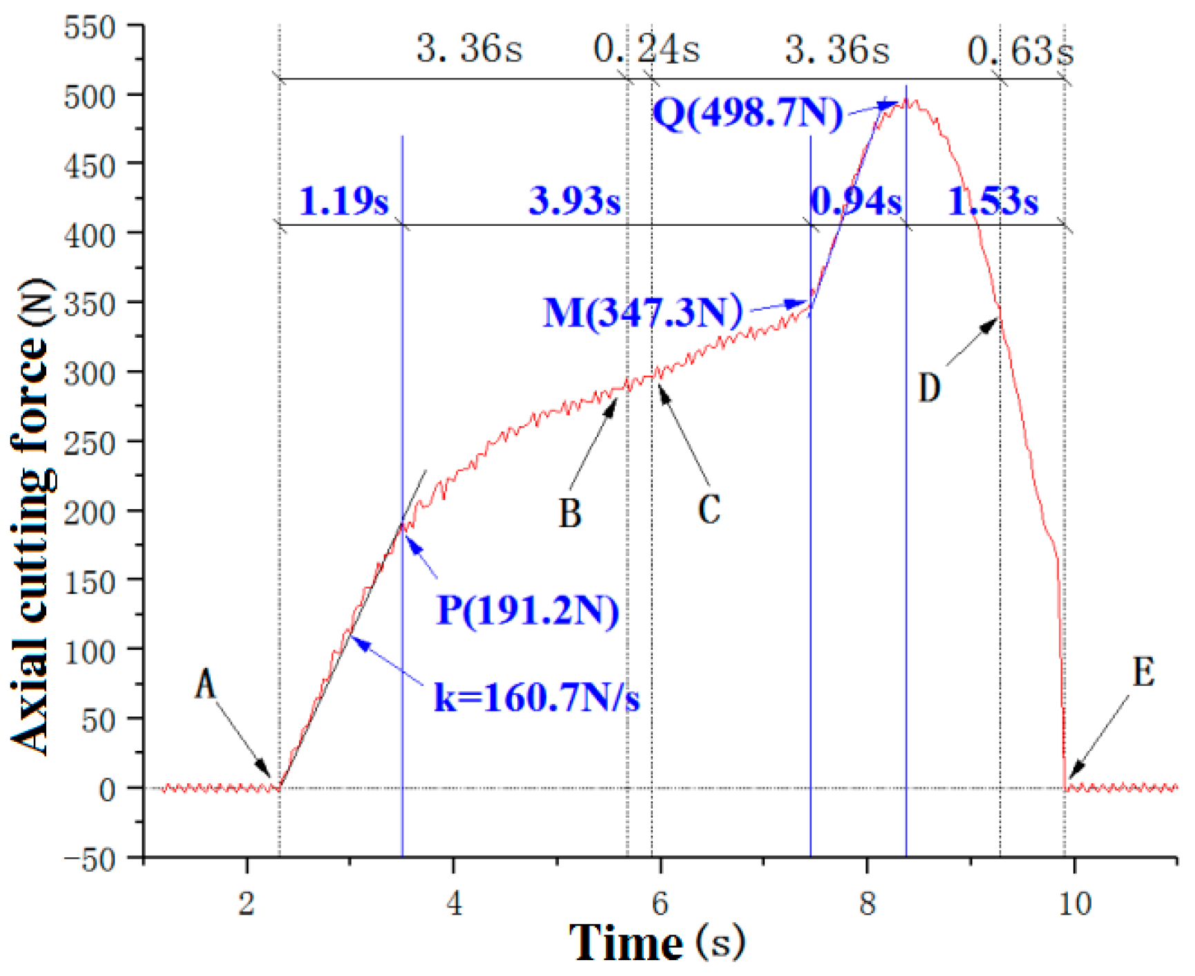
f = 0.025 mm/r, workpiece overhang size (length × width × thickness) of 70 mm × 70 mm × 1.5 mm, and dry cutting conditions, and the variation in axial force with time is shown in
Figure 3, and the points labeled in the figures. Points A, B, C, D, and E correspond to the theoretical drilling characteristic points shown in
Figure 2.
As can be seen from
Figure 3, from the beginning of drilling to the axial force decreasing to 0 (
Figure 3, A–E), the actual drilling time lagged about 0.63 s compared with the theoretical drilling time without considering the deformation of the thin-walled plate (
Figure 2, A–D), which indicates that the thin-walled plate had undergone overall convex deformation under the action of axial force during the drilling process, so that the time from the contact of the drill bit with the workpiece’s upper surface to the intersection of the drill bit main and vice cutting edges drilling to the bottom of the workpiece was increased.
From the curve of axial force with drilling time in
Figure 3, the change in axial force during the drilling process can be divided into four stages in general: In the first stage (corresponding to the straight line segment between point A and point P in the figure), the axial force rises in a straight line with a large slope, and the axial force is mainly caused by elastic deformation resistance of the workpiece, which lasts significantly longer than the difference between actual and theoretical drilling time (0.63 s). The axial force is mainly caused by the elastic deformation resistance of the workpiece, and the duration (1.19 s) is significantly larger than the difference between the actual drilling and theoretical drilling time (0.63 s). In the second stage, the axial force shows a curved increase at the initial stage and basically increases linearly at the later stage; when the elastic resistance of the workpiece increases to a certain value in the first stage, the drill starts to drill into the workpiece, and at the initial stage, the main cutting edge has just cut into the workpiece, and the axial force is mainly caused by the extrusion of the top cutting edge; at the later stage, with the drill drilling, the role of the top cutting edge stabilizes, and the length of the main cutting edge involved in the cutting increases gradually, and the axial force increases approximately and linearly at a relatively small slope. In the second stage, the increase in axial force after drilling is smaller than the elastic resistance generated in the first stage, and it can be assumed that this stage is mainly dominated by the drilling of the drill bit, and at the same time, due to the production of a certain amount of elastic recovery of the thin-walled plate, the actual drilling thickness is greater than the feed amount, which is one of the reasons why the difference between the actual drilling and the theoretical drilling time is less than the duration of the overall convex deformation at the early stage of the drilling process. In the third stage (between points M–Q in the figure), the axial force increases rapidly with a large slope to the maximum value of the whole drilling process. In the fourth stage, the axial force decreases rapidly after reaching the maximum value. The variation characteristics of the axial force during the drilling of thin-walled AF1410 high-strength steel plates are completely different from those of the brittle SiCp/Al composite material, which experiences a sudden drop in axial force when the drill bit is about to exit the bottom surface of the workpiece [
27].
Theoretically, if the deformation of the workpiece is not taken into account, the maximum value of axial force should occur between the characteristic points B–C (
Figure 2), i.e., the main cutting edge enters into the workpiece completely, and the top edge is not yet drilled out of the position; however, from the axial force waveform in
Figure 3, the maximum value of the axial force is obviously lagging behind that at the points B However, from the axial force waveform in
Figure 3, the maximum value of axial force is obviously lagging behind the point B–C, and at the theoretical characteristic points B and C, the axial force is in the state of steady increase, which indicates that the top edge of the drill bit is not drilled to the bottom surface of the workpiece, which is mainly caused by the fact that under the action of the axial force, the overall cambering deformation of the workpiece lags behind the relative position of the drill bit and the workpiece.
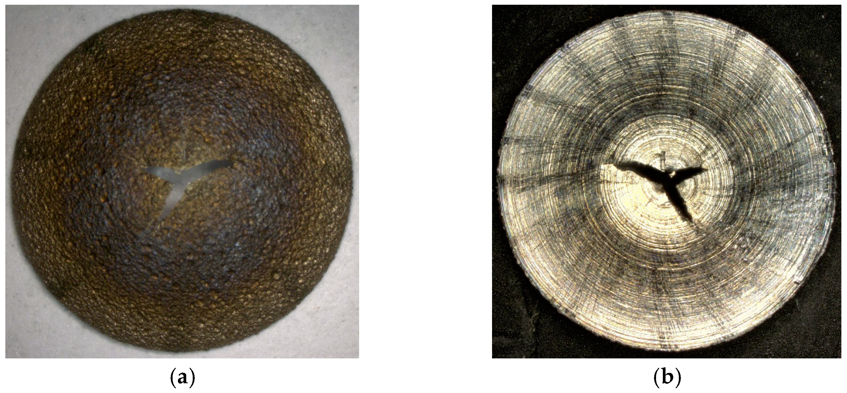
In addition, AF1410 high-strength steel is a high-strength plastic material with poor thermal conductivity. Under the action of axial force and drilling temperature, not only does the overall convex deformation occur during the drilling process, but also a large local plastic deformation occurs when the drill tip is about to drill out of the bottom surface of the workpiece, resulting in the formation of a complete conical cap whose inner surface coincides with the rotating cone surface of the drill tip as shown in
Figure 4. Due to the high strength of AF1410 high-strength steel, the drill caps and edge profiles formed during thin-walled drilling are significantly different from the exit profiles of titanium alloy drilling reported in Reference [
26]. This also results in distinct characteristics of the drilling axial force compared to titanium alloy drilling.
Based on the analysis of the characteristics of axial force and deformation changes during the drilling process of high-strength steel thin-wall panels, the schematic diagram of workpiece deformation during the drilling process is shown in
Figure 5.
In
Figure 5, a is the top edge of the drill bit just contacting the upper surface of the workpiece; a–b is the stage of elastic deformation of the lower convexity of the workpiece; at this stage, although the top edge of the drill bit exerts a large extrusion friction on the workpiece, it is not drilled into the workpiece, and the main body manifests itself as the lower convexity elastic deformation of the workpiece, and the axial force grows linearly, and the elastic deformation and the elastic resistance of the workpiece in the position of b reach the maximum; b–c is the stage of the drill bit drilling into the workpiece, and at this stage, the lower convex elastic deformation of the workpiece is basically in a stable state, under the support of elastic resistance, the drill bit gradually drills into the workpiece, and the axial force increases with the increase in the drilling length of the main cutting edge; d is the stage of local deformation under the tip of the drill bit, and the center of the drill bit cracks after the top edge of the tip is pushed out from the bottom of the workpiece; e is the stage of the local plastic shaped of the workpiece under the main cutting edge of the drill bit, which gradually forms the drilling cap, and the axial force first starts to increase rapidly and reaches its maximum. The axial force at this stage first starts to increase rapidly, reaches the maximum value, and then decreases rapidly. f is the intersection of the main and secondary cutting edges of the drill bit drilling to the bottom surface of the workpiece, and the drill cap is separated from the bottom surface of the workpiece by fracture, and the axial force decreases to zero.
From
Figure 4, the morphology of the drill cap can be seen. AF1410 high-strength steel thin-walled plate drilling formed by the inner surface of the drill cap and the drill tip rotary taper coincides with the formation of the drill cap process, mainly manifested as the tip of the drill below the workpiece to be processed layer of local plastic deformation. The formation of the cap first occurs in the top edge of the layer to be machined below the top edge, in the top edge drilling to the position near the bottom surface of the workpiece, in the axial force and drilling temperature under the action of the top edge of the layer to be machined under the action of the local plastic convex deformation; at the same time, the top edge of the top edge and the main cutting edge of the ring edge machining layer adjacent to the role of the part of the material in the tip of the taper of the action of the material under the stress to the material bending yield strength, the occurrence of the outward turning of the plastic deformation. With the feed of the drill bit, the material of the machining layer near the bottom surface of the workpiece in contact with the main cutting edge of the annular region continuously yields and turns out, forming the drill cap. In the process of forming the drill cap, the top edge of the drill bit is mainly used for the rotary extrusion of the layer material to be processed underneath, and the main cutting edge and the main back face are mainly used for cutting and rotary pressure; for the part farther away from the bottom surface, the thickness is larger, and the rigidity can still support the cutting force to produce a certain degree of cutting, and for the part close to the bottom surface, the thickness is small, and the rigidity is not enough to support the cutting when the rotary pressure is mainly used for extruding. At the beginning of the formation of the drill cap, the axial force increases rapidly with a large growth slope; with the continued feeding of the drill, the thickness of the workpiece machining layer corresponding to the bottom of the main cutting edge of the drill and the remaining annular width decrease, the stiffness decreases, and the axial force reaches its maximum value when its stiffness is not enough to support the cutting action of the main cutting edge and the overall yield occurs; the maximum thickness of the workpiece machining layer corresponding to the bottom of the main cutting edge at this point in time is known as the critical thickness. The maximum thickness of the workpiece layer below the main cutting edge at this time is called the critical thickness. Subsequently, as the drill continues to feed, the axial force decreases rapidly and is conical to expand outward under the action of the taper surface of the drill tip. When the intersection of the main and secondary cutting edges of the drill is actually drilled to the bottom surface of the thin-walled plate, the edge of the taper surface is fractured, the drilling cap and the substrate are separated, the deformed workpiece is rebounded, and the axial force rapidly decreases to 0. Yield outward flopping of the edge of the borehole wall under the tip of the drill speeds up the elastic recovery of the thin-walled plate, and this also makes the actual drilling lag time smaller than the overall convex deformation duration at the beginning of drilling.
3.2. Influence of Cutting Speed (Spindle Speed) on Axial Force and Deformation in Drilling
Under the conditions of feed
f = 0.025 mm/r and dry cutting, the cutting speed
v = 12.6~37.7 m/min (spindle speed
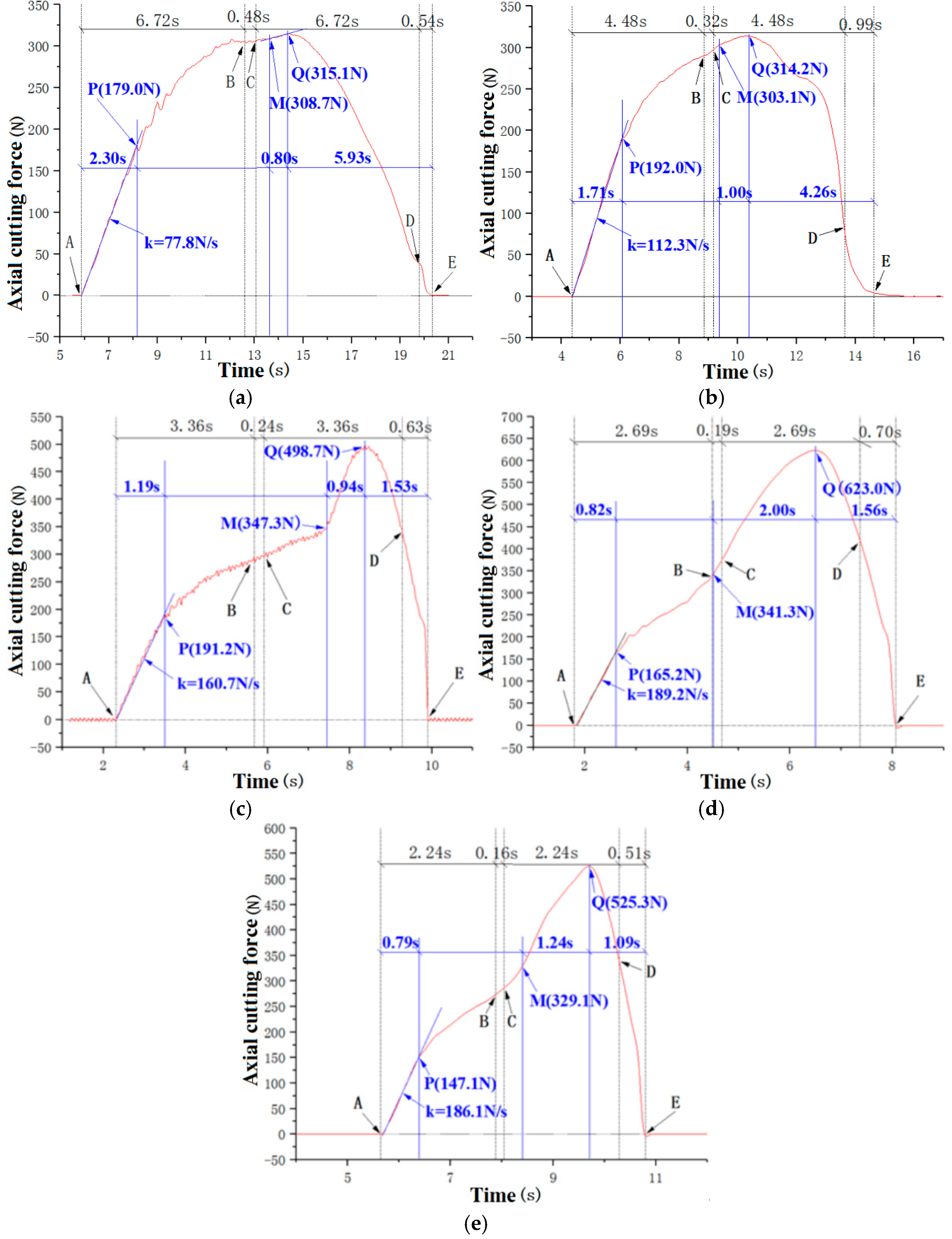
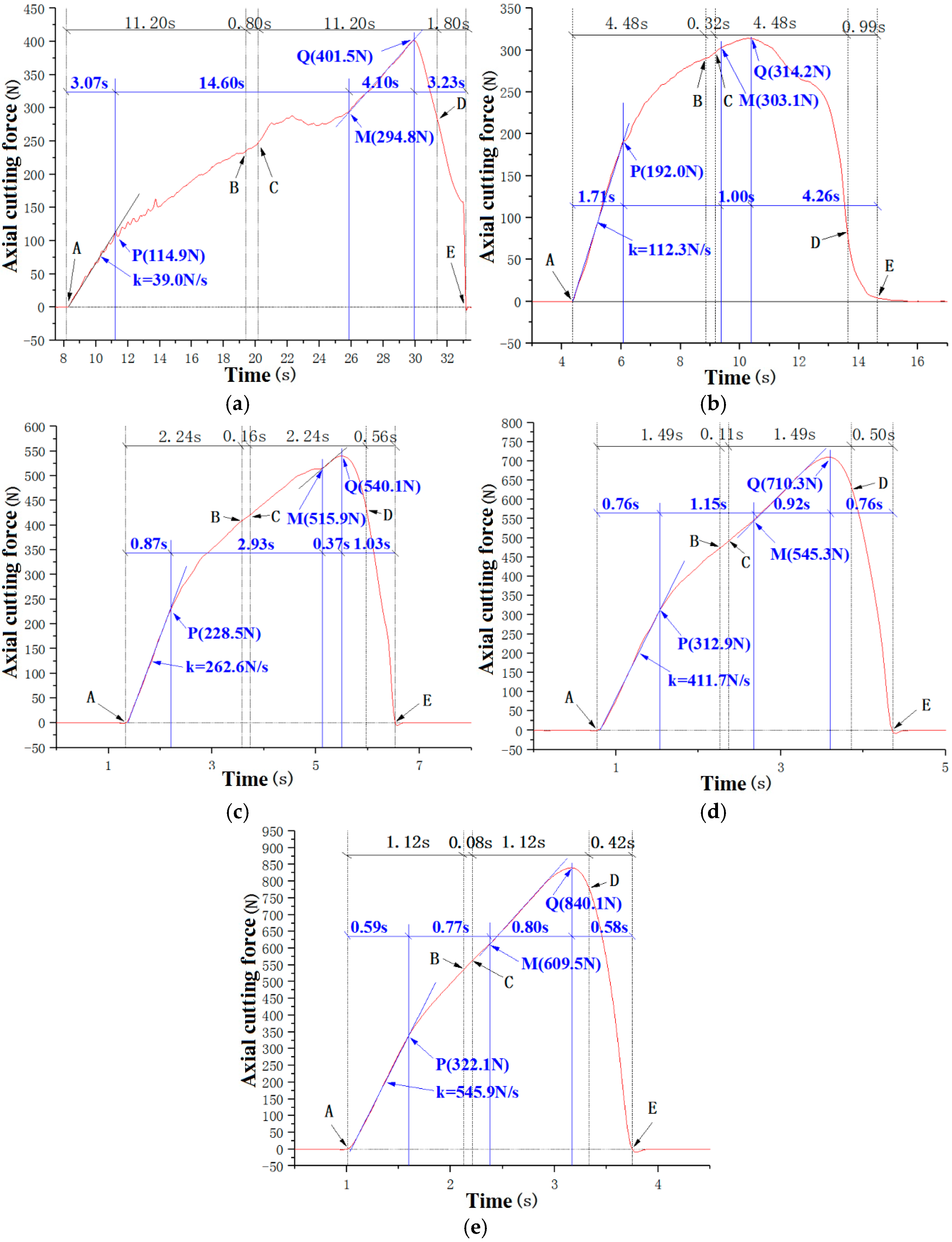
n = 500~1500 r/min) was varied to study the effect of cutting speed on the axial force of drilling. The waveforms of axial force with time at different cutting speeds (rpm) are shown in
Figure 6.
As can be seen from
Figure 6, the axial force of drilling thin-walled plates of AF1410 high-strength steel at different drilling speeds generally exhibits the same change characteristics as those described before. Among them, in the range of higher cutting speed
v = 25.1–37.7 m/min (
n = 1000–1500 r/min), the axial force waveform graphs have higher similarity, and there is an obvious rapid increase in the process of drill cap formation in the late stage of drilling; while in the range of lower cutting speed
v = 12.6–18.8 m/min (
n = 500–750 r/min), the axial force in the increase in axial force in the process of drilling cap formation is more gentle, and the lower the speed, the more gentle.
From the time of generation of the maximum axial force, at the cutting speed v = 25.1–37.7 m/min (n = 1000–1500 r/min), the generation of the maximum axial force is closer to the intersection point of the main and secondary cutting edges where the bottom surface of the workpiece is to be drilled out; and at the low cutting speed range of v = 12.6–18.8 m/min (n = 500–750 r/min), the generation of the maximum axial force slightly deviates from the theoretical position of the top edge of the drill bit where the bottom surface of the workpiece is to be drilled out. In the low cutting speed range of v = 126–18 m/min (n = 500–750 r/min), the maximum axial force is slightly deviated from the theoretical position of the top edge of the drill bit to drill out the bottom surface of the workpiece, and considering the effect of convex deformation of the workpiece at the initial stage of drilling, the maximum axial force occurs at the position of the top edge of the drill bit when the drill bit is actually about to be drilled out, which indicates that the maximum axial force occurs due to different reasons at different cutting speeds.
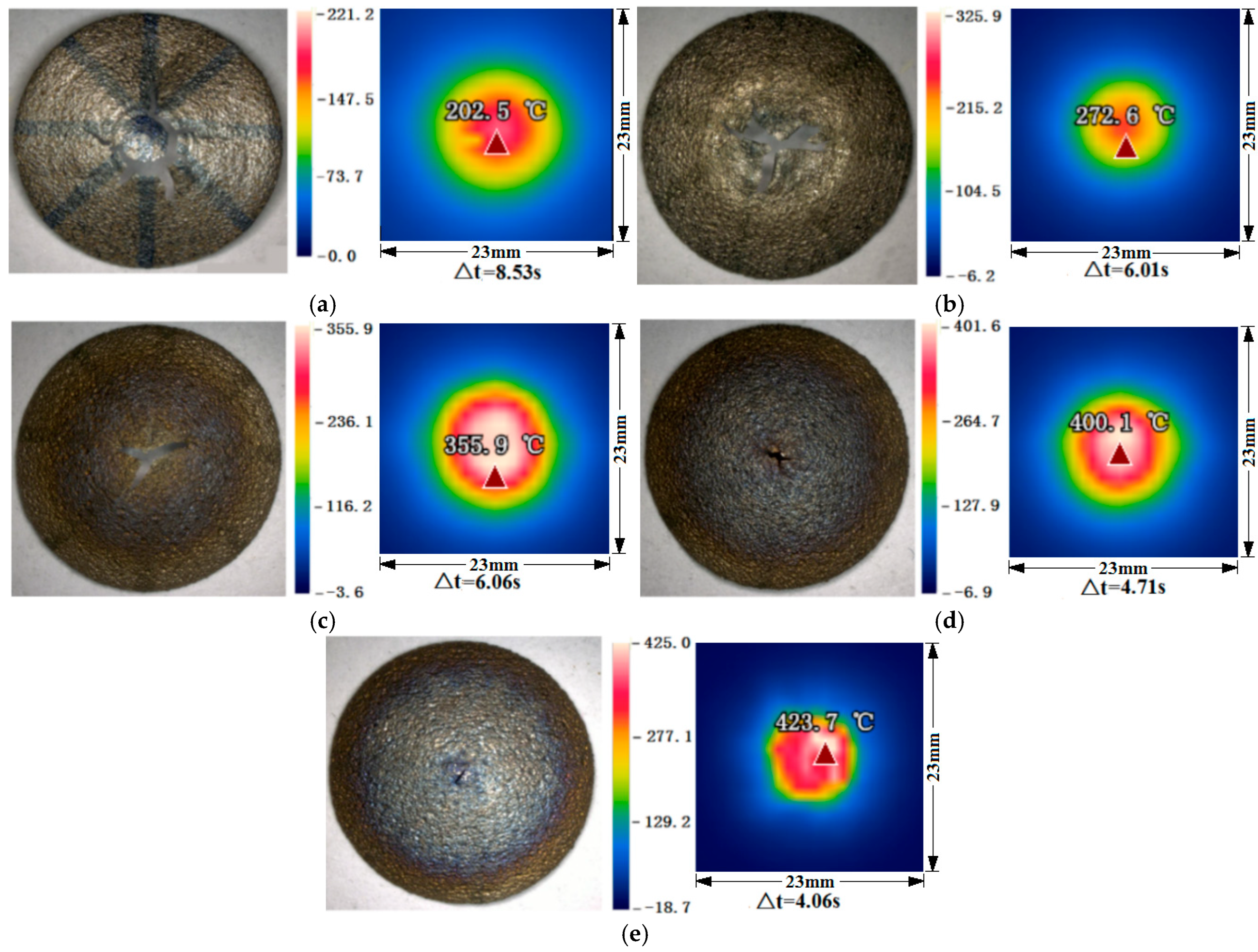
This change in axial force with cutting speed is characterized by the temperature of the bottom of the workpiece corresponding to the drill tip during the formation of the drill cap.
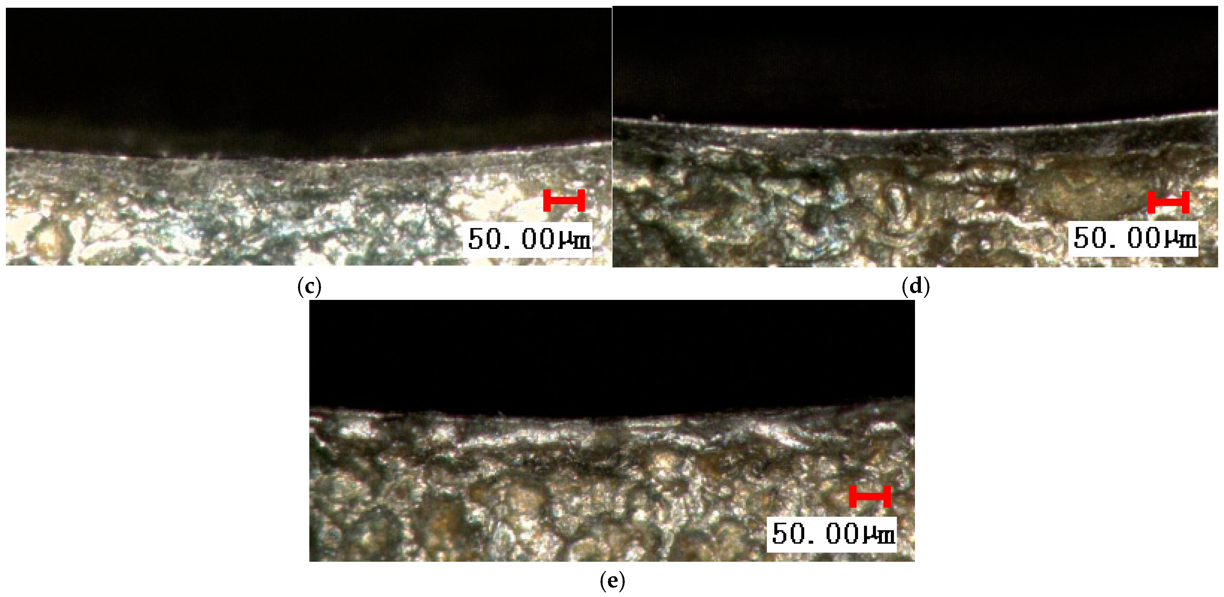
Figure 7 shows the morphology of the drill cap formed at different cutting speeds and the temperature field at the time of maximum axial force.
From the color of the drill cap and the temperature field of the bottom surface of the workpiece, it can be seen that the temperature of the bottom surface of the drill cap increases greatly with the increase in the cutting speed. Due to the increase in temperature in the process of cap formation at higher cutting speed, the yield strength of AF1410 high-strength steel decreases with the increase in temperature [
28], the bottom material of the workpiece corresponding to the drill tip is more prone to thermoplastic deformation, and the cap formation is dominated by the rotational extrusion of the drill tip on the bottom material of the workpiece, so that the thickness and width of the machined layer of the workpiece corresponding to the main cutting edge below the main cutting edge under the process of cap formation increase, and the increase in the axial force is mainly caused by the rotational extrusion of the drill tip on the bottom material of the workpiece, and the axial force increases in the intersection point of the main and secondary cutting edges close to the bottom surface of the workpiece. The increase in axial force is mainly caused by the rotational extrusion of the drill tip on the workpiece material at its bottom, and the axial force reaches the maximum when the intersection point of the main and vice cutting edges is close to the bottom surface of the workpiece, and the workpiece machining layer corresponding to the workpiece below the main cutting edge undergoes the overall outward plastic deformation, and then it decreases rapidly with the plastic yielding. When the cutting speed is low, during the formation of the drill cap, the temperature of the material on the bottom surface of the workpiece corresponding to the drill tip is low, and the hardness and stiffness are large, so that the bearing capacity of the axial drilling force during the formation of the drill cap is large, and the thickness and width of the plastic deformation of the whole outward turning of the main and vice cutting edges are small when the main cutting edge is about to be drilled out of the bottom surface of the workpiece, at this time, the axial force is also small, and the largest axial force occurs in the early stage of the formation of the drill cap, and the top cutting edge of the drill bit is about to be drilled out of the bottom surface of the workpiece. The maximum axial force occurs at the early stage of cap formation, when the top edge of the drill bit is about to drill out the bottom surface of the workpiece. From the photo of the morphology of the drill cap, when the cutting speed is lower, the rupture opening in the center of the drill cap is larger, and with the increase in cutting speed, the drilling temperature rises, the material softens, the plasticity increases, the cracks at the top of the drill cap become smaller, and the drill cap tends to be complete.
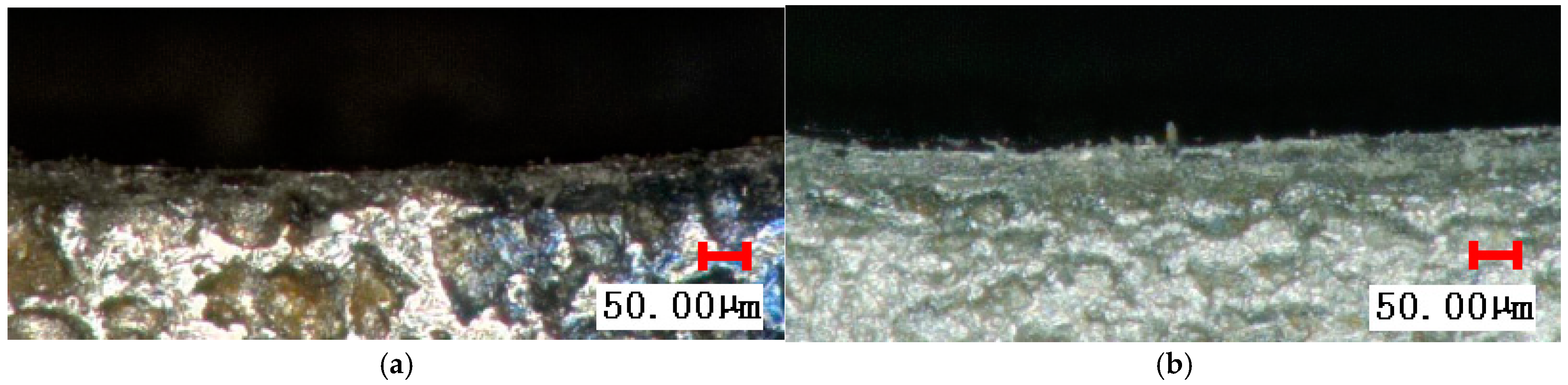
Different cutting speeds under the formation of the characteristics of the drill cap directly affect the formation of edge defects in the workpiece; if the cutting speed is higher, the main cutting edge below the corresponding workpiece processing layer occurs as a whole when the thickness of the plastic deformation of the flap is greater; the edge of the plastic deformation caused by the crimping and other defects is greater. When the cutting speed is lower, the edge of the main cutting edge by the drill cutting edge cutting is completed, and the edge is more flat, as shown in
Figure 8.
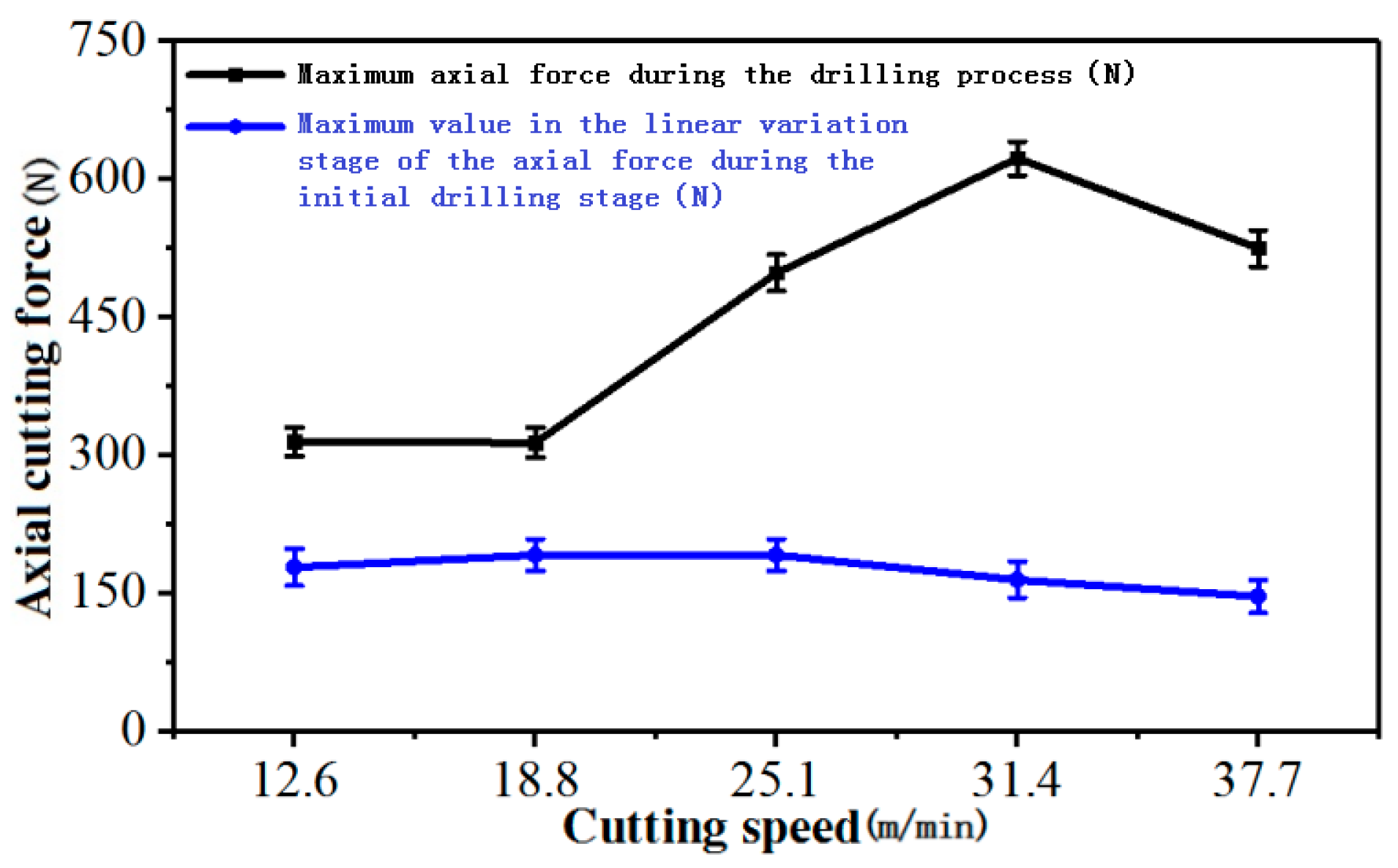
The effect of cutting speed on the maximum axial force during drilling and the maximum value of axial force at the initial stage of linear variation in axial force during cutting is shown in
Figure 9.
As can be seen from
Figure 9, the maximum values of the axial force at the stage of linear change at the early stage of drilling do not differ much, and the cutting speed has less influence on it. The previous analysis shows that, due to the low stiffness of the thin-walled plate of AF1410 high-strength steel, at the initial stage of the drill contacting the workpiece, the workpiece undergoes elastic convex deformation under the action of the axial force of the top edge of the drill, and the drill does not cut into the workpiece obviously, and the axial force is mainly caused by the elastic resistance of the workpiece, and the maximum axial force at this stage depends on the support force required for the drill to cut into the workpiece, and the drill only starts to cut into the workpiece when the elastic resistance is sufficient to support the drill to cut into it. When the elastic resistance force is enough to support the drill bit to drill into the workpiece, the drill bit starts to cut into the workpiece. The results in
Figure 9 show that the cutting speed has little effect on the support condition of the drill bit to drill into the workpiece. The previous analysis shows that the maximum axial force occurs when the cutting speed
v = 25.1~37.7 m/min (
n = 1000~1500 r/min) is about to be drilled out of the bottom surface of the workpiece at the intersection point of the main and vice cutting edges, which is caused by the plastic flanging deformation that occurs underneath the cutting edge, and the thickness and width of the flanging deformation occurring underneath the drill bit is not affected by the increase of the cutting speed from 25.1 m/min to 31.4 m/min due to the increase in temperature of the material underneath the drill tip. When the cutting speed increases from 25.1 m/min to 31.4 m/min due to the increase in temperature of the material below the drill tip, the thickness and width of the flanging deformation increase, and the maximum axial force increases, but with the further increase in cutting speed to 37.7 m/min, due to the further increase in temperature, the material softens, and the maximum axial force decreases to a certain extent. Considering
Figure 6 and
Figure 8, if one wants to achieve better hole exit edge quality with smaller edge defect dimensions, the cutting speed should be less than 25.1 m/min.
The previous analysis shows that at the early stage of drilling, due to the low stiffness of the workpiece, the elastic convex deformation occurs under the pressure of the top edge, the drill bit does not drill into the workpiece, the axial force grows linearly, and the moving distance of the drill bit at this stage is approximated to the amount of convex deformation of the center of the workpiece. If the time of linear growth of axial force in the early stage of drilling is △
t, then the convex deformation
Δ (mm) is as follows:
In Equation (2), n is the spindle speed (r/min) and f is the feed (mm/r).
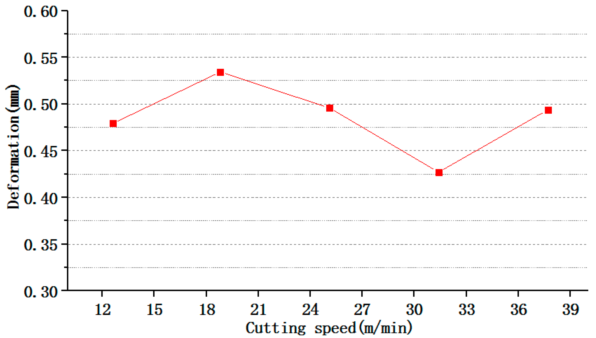
The effect of cutting speed on the amount of convex deformation of the workpiece at the initial stage of drilling is thus calculated as shown in
Figure 10.
As seen in
Figure 10, the cutting speed has little effect on the elastic convex deformation of the workpiece before the drill bit drills into the thin-walled plate at the initial stage of drilling. Since the elastic convex deformation of the workpiece before drilling in directly affects the size and shape accuracy of the hole after the workpiece elasticity is recovered, the results in
Figure 10 also show that the cutting speed has little effect on the size and shape accuracy of the hole due to elastic deformation of the drilling process of the thin-walled plate of high-strength steel.
3.3. Influence of Feed on Axial Drilling Force
Under the conditions of a workpiece overhang size of 70 mm × 70 mm, a thickness of 1.5 mm, 2-side constraint (left and right opposite sides fixed), a cutting speed of
v = 18.8 m/min (spindle speed
n = 750 r/min), a feed of
f = 0.01–0.1 mm/r, and dry cutting conditions, the variation in axial force with time under different feeds is shown in
Figure 11.
For the same reason as mentioned above, the axial force at the beginning of drilling increases linearly under different feeds; after the drill bit is drilled into the workpiece, the axial force increases with the increase in the cutting length of the main cutting edge of the drill bit, and the slope of its increase is smaller than that at the beginning of the drilling; however, the position point of the maximum axial force and the characteristics of the axial force waveforms are different under different feeds.
The trend of the axial force waveforms is basically the same in the case of f = 0.01 mm/r and f ≥ 0.05 mm/r, and the latter part of the axial force waveform in the case of f = 0.01 mm/r is characterized by more obvious plastic deformation of the drill cap.
When
f = 0.01 mm/r, the feed amount is too small; due to the influence of cutting edge radius, in the process of drilling, the extrusion friction effect is larger, the temperature of the bottom surface below the drill tip is higher (
Figure 12), and the contact area between the drill tip and the workpiece is more prone to plastic deformation, and in the intersection point of the main and secondary cutting edges of the drill bit when it is about to be drilled out of the bottom surface of the workpiece, the plastic outward flap occurs so that the axial force increases rapidly, and the plastic deformation resistance decreases rapidly after the maximal value is reached. When
f = 0.025 mm/r, as mentioned in
Section 3.2, the process of drilling cap formation is dominated by cutting action, and the contact area between the main cutting edge and the workpiece machining surface undergoes plastic deformation in the small thickness to form the drilling cap.
f = 0.05 mm/r, the axial force in the process of drilling cap formation shows a small increase, and no significant sudden change in axial force occurs due to the larger plastic deformation. There is no significant change in axial force due to large outward plastic deformation.
With the further increase in feed, after
f ≥ 0.075 mm/r, the slope of the increase in the axial force in the second stage and the increase in the axial force in the third stage converge. With the increase in the feed volume, the drilling speed of the drill bit is fast, and the axial force increase rate after the main cutting edge is drilled in becomes larger, at the same time, from the temperature field of the bottom surface of the workpiece at the time of the maximum drilling force (
Figure 12), the maximum temperature of the bottom surface temperature field increases correspondingly with the increase in the feed volume, and the degree of thermal softening of the workpiece material in the process of drilling is increased, and the axial force of plastic deformation of the drilling cap camber decreases, so that the axial force increase in the second stage and the axial force increase in the third stage are consistent. The slope of the increase in the axial force in the second stage and the third stage is close to the same.
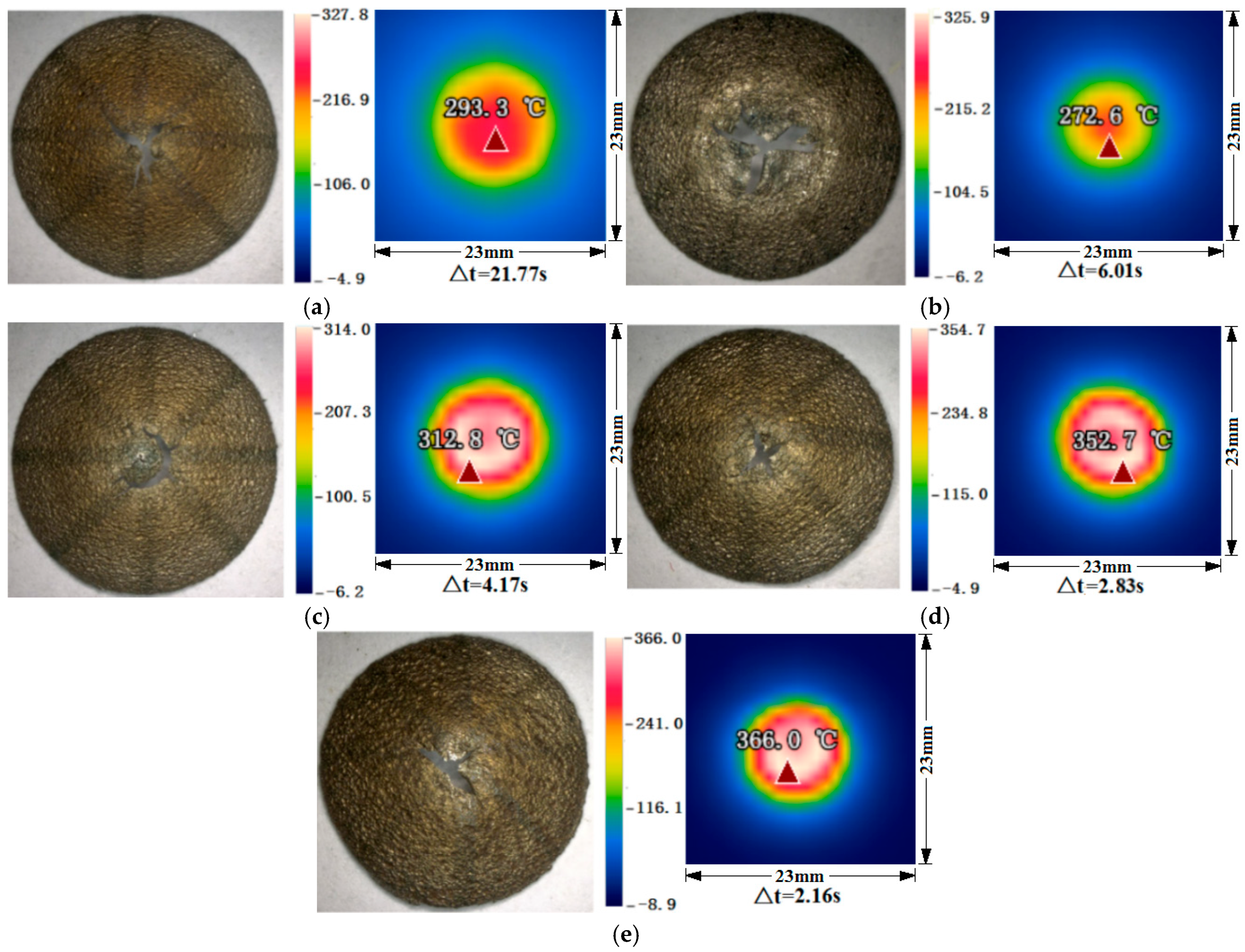
Figure 12 shows the morphology of the drilling cap and the temperature field when the axial force is maximized at different feeds
f.
From the temperature field of the bottom surface of the drill cap formation process, it can be seen that the temperature is higher after the feed amount f = 0.01 mm/r and f ≥ 0.05 mm/r. Due to the higher temperature in the cutting zone during the formation process of the drill cap, the material at the bottom surface of the workpiece corresponding to the drill tip undergoes localized softening, and the formation of the drill cap is dominated by the rotational extrusion of the drill tip on the material of the workpiece at the bottom surface of the drill tip.
In
Figure 12, when the feed rate
f = 0.025 mm/r, during the process of top hat formation, the temperature of the bottom material of the workpiece corresponding to the drill tip is low, and the hardness and strength are high, so in the early stage of top hat formation, it is mainly the cutting of the main cutting edge of the drill tip, and therefore the change in axial force is relatively smooth. When the top edge drills through the top of the cap, the axial force decreases. It can also be seen from the morphology of the drill cap that the top crack of the drill cap is larger when the feed
f = 0.025 mm/r.
The characteristics of drilling cap formation under different feeds also directly affect the formation of workpiece edge defects. At
f ≥ 0.05 mm/r, the axial force and temperature in the process of drilling cap formation are higher, and the overall increase with the increase in feed, the critical thickness and width of the workpiece machining layer corresponding to the overall outward plastic deformation below the main cutting edge increase accordingly, and the edge of the edge by the plastic deformation caused by the crimping and other defects is larger. At
f = 0.01 mm/r, the temperature of the bottom surface below the drilling tip is higher, and the exit of the hole also has obvious crimping. As shown in
Figure 13, the edge of the hole is relatively flat, 0.01 mm/r, the temperature of the bottom surface below the drill tip is higher, and the exit of the hole has an obvious curling edge. At
f = 0.025 mm/r, the edge of the hole is more flat, as shown in
Figure 13.
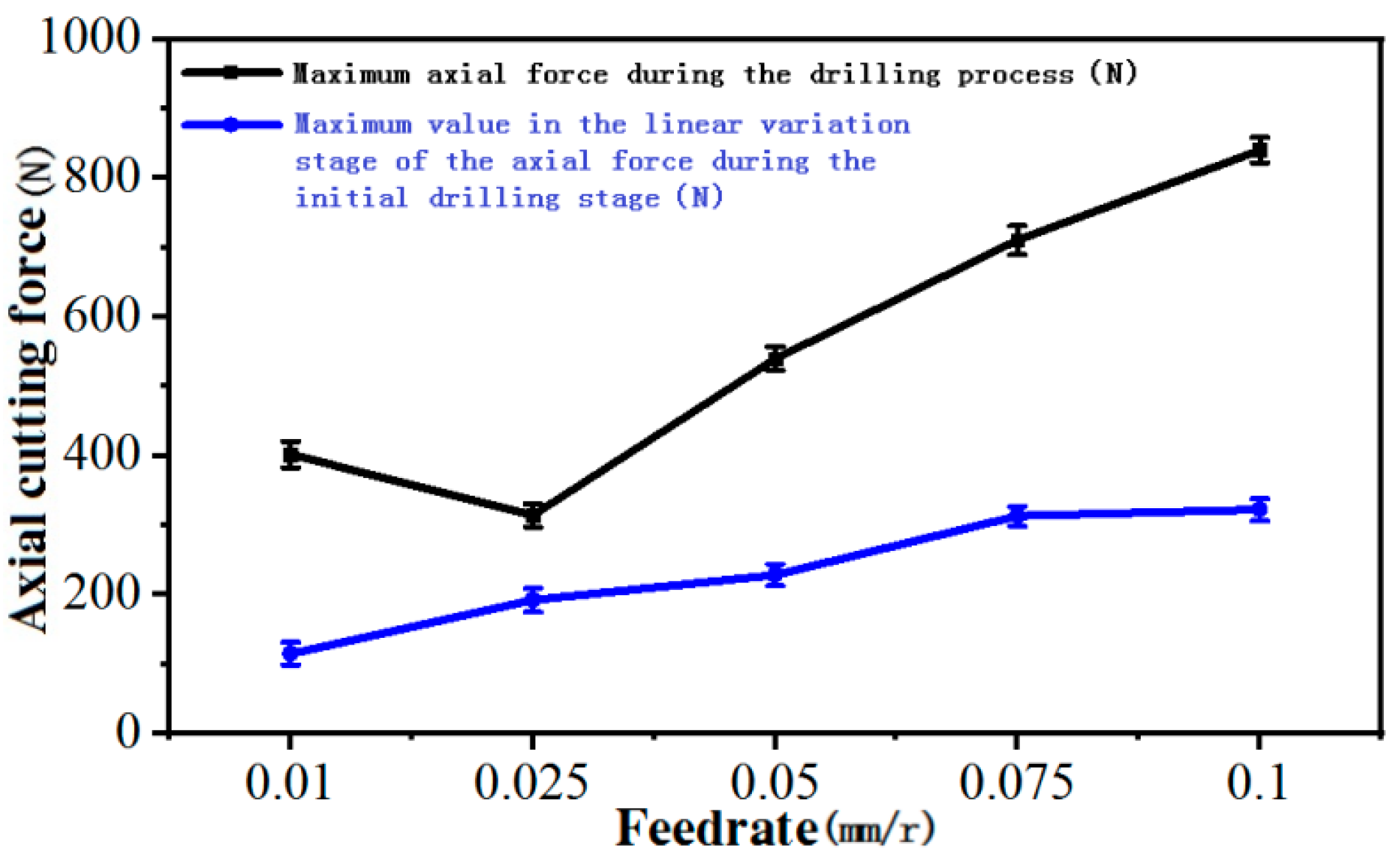
The effect of feed on the maximum axial force during drilling and the maximum value of axial force in the linear change stage at the beginning of cutting is shown in
Figure 14.
From
Figure 14, it can be seen that the axial force at the stage of overall convex deformation of the thin-walled plate at the early stage of cutting increases slowly with the increase in feed
f. This indicates that the feed has a certain influence on the conditions of the drill bit drilling into the thin-walled plate at the early stage of drilling, and the increase in axial force at a smaller feed is smaller, and the support force required by the drill bit for drilling into the workpiece is smaller, so the drill bit can start drilling into the workpiece after the thin-walled plate produces a smaller convex deformation; with the increase in feed, the support force required for drilling into the workpiece increases, and the drill can only drill into the workpiece after the thin-walled plate produces a larger convex deformation. From
Figure 13, the maximum axial force changes to see the overall maximum axial force with the increase in feed f and increase; the reason is the same as the aforementioned. At
f = 0.01 mm/r, due to the feed being too small, the extrusion of the drilling edge of the role of the large, the maximum axial force is instead larger. Considering
Figure 11 and
Figure 13, if one wants to achieve better hole exit edge quality with smaller edge defect dimensions, the feed rate should be less than 0.05 mm/r.
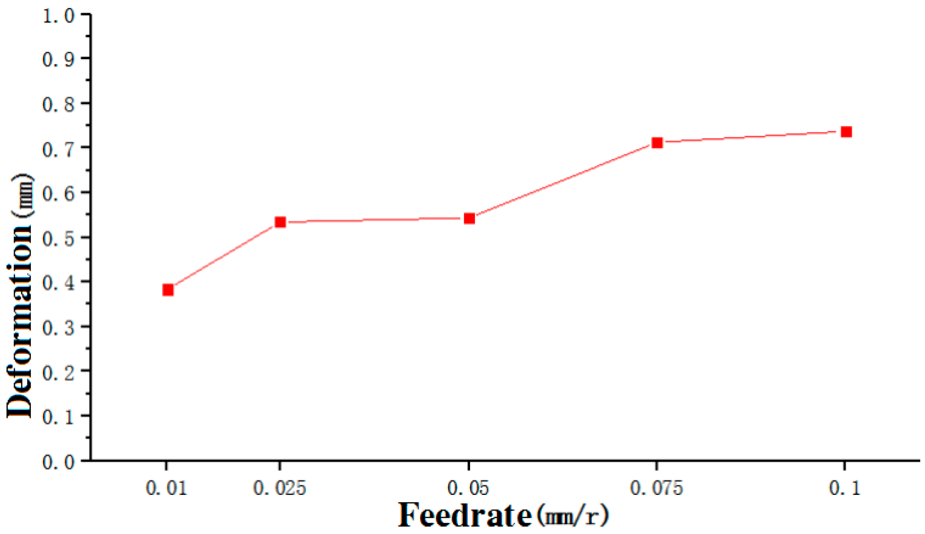
Calculated according to Equation (2), the variation in convex deformation produced by the thin-walled plate before drilling into the drill bit with the feed amount is shown in
Figure 15.
As can be seen from
Figure 15, the amount of convex deformation of the thin-walled plate before drilling into the drill increases with the increase in feed; the axial force is small when the feed is small, and the support force required for the drill to drill into the workpiece is small, so the drill starts to drill into the workpiece after the thin-walled plate produces a small convex deformation; with the increase in feed, the support force required for the drill to drill into the drill increases, and the thin-walled plate can only be drilled into the workpiece after the drill produces a large convex deformation.


