
Analytical Investigation of Electromechanical Hierarchical Metamaterials for Vibration Attenuation and Energy Harvesting

Abstract
1. Introduction
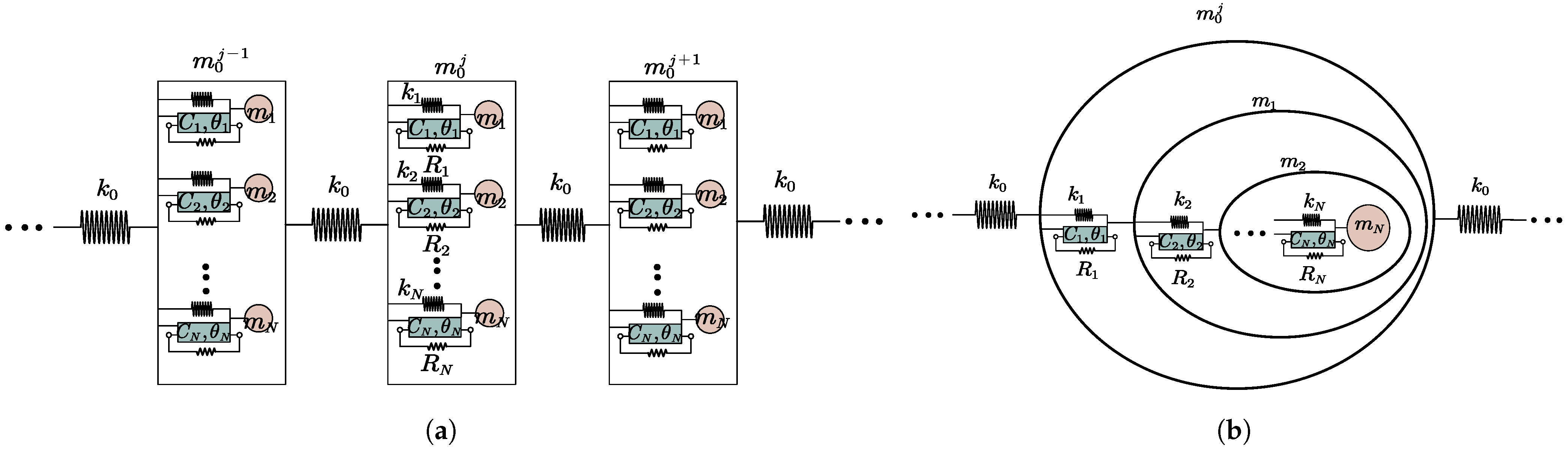
2. Mathematical Modeling
3. Band Structure of Hierarchical Metamaterials
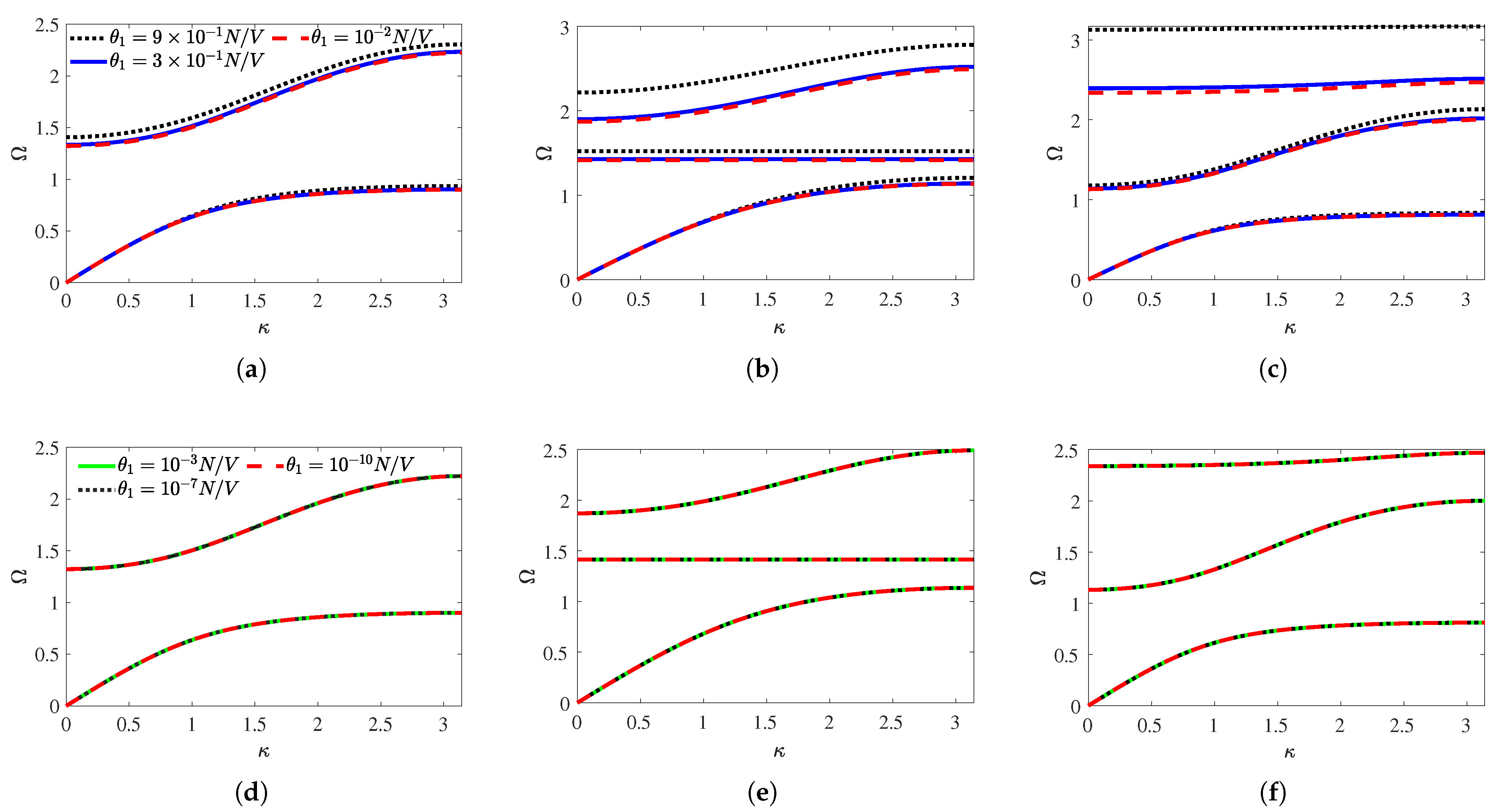
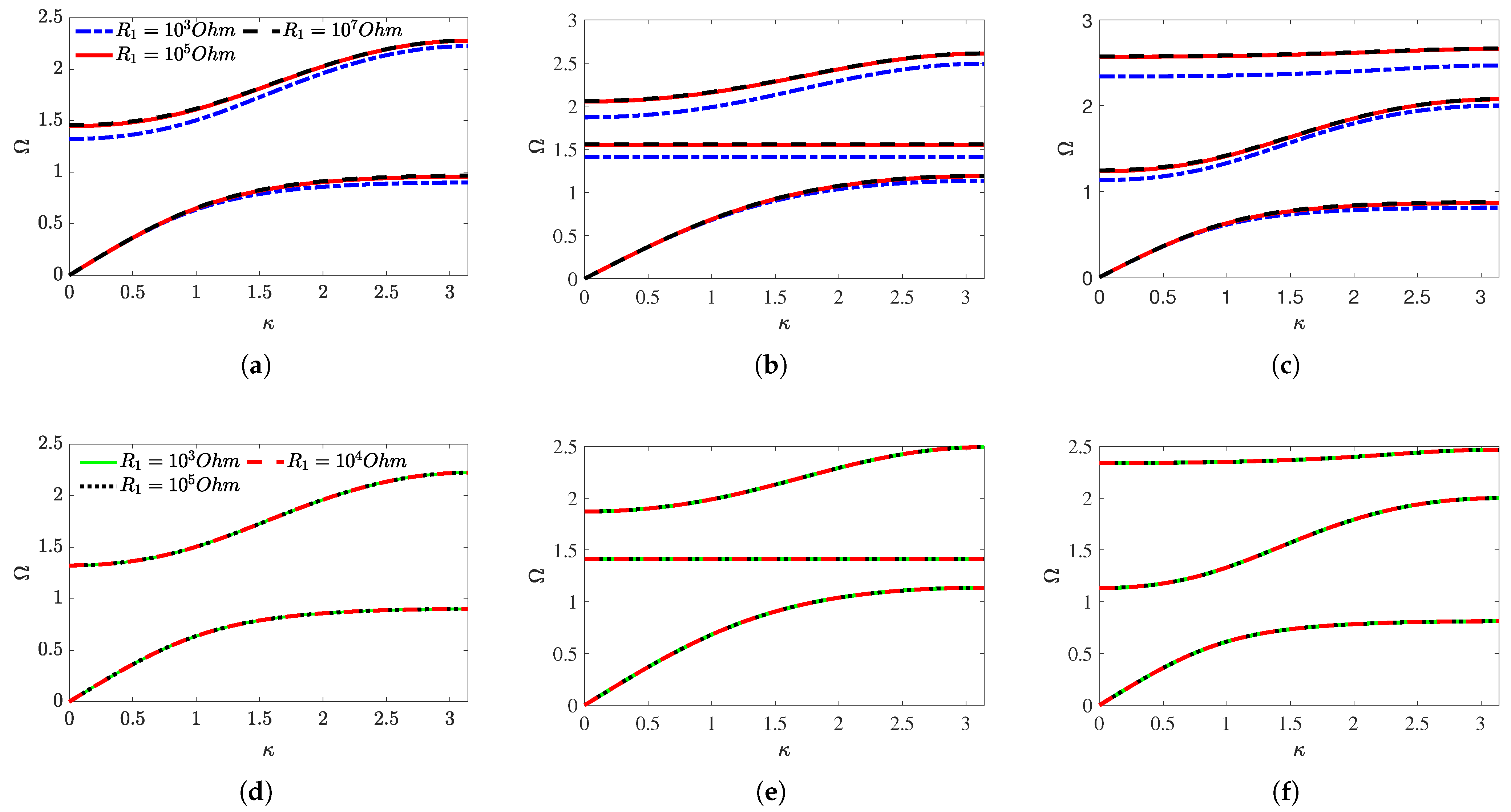
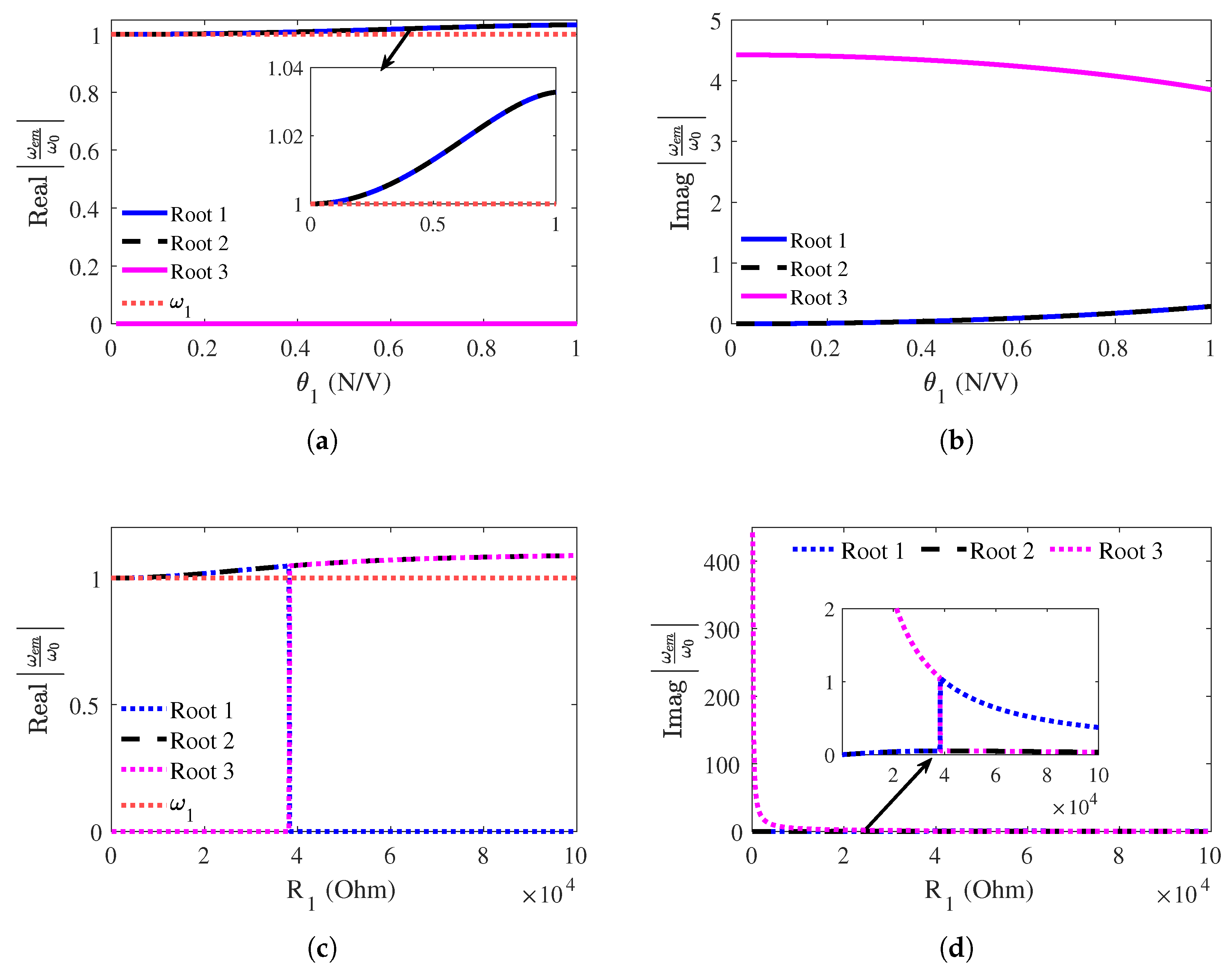
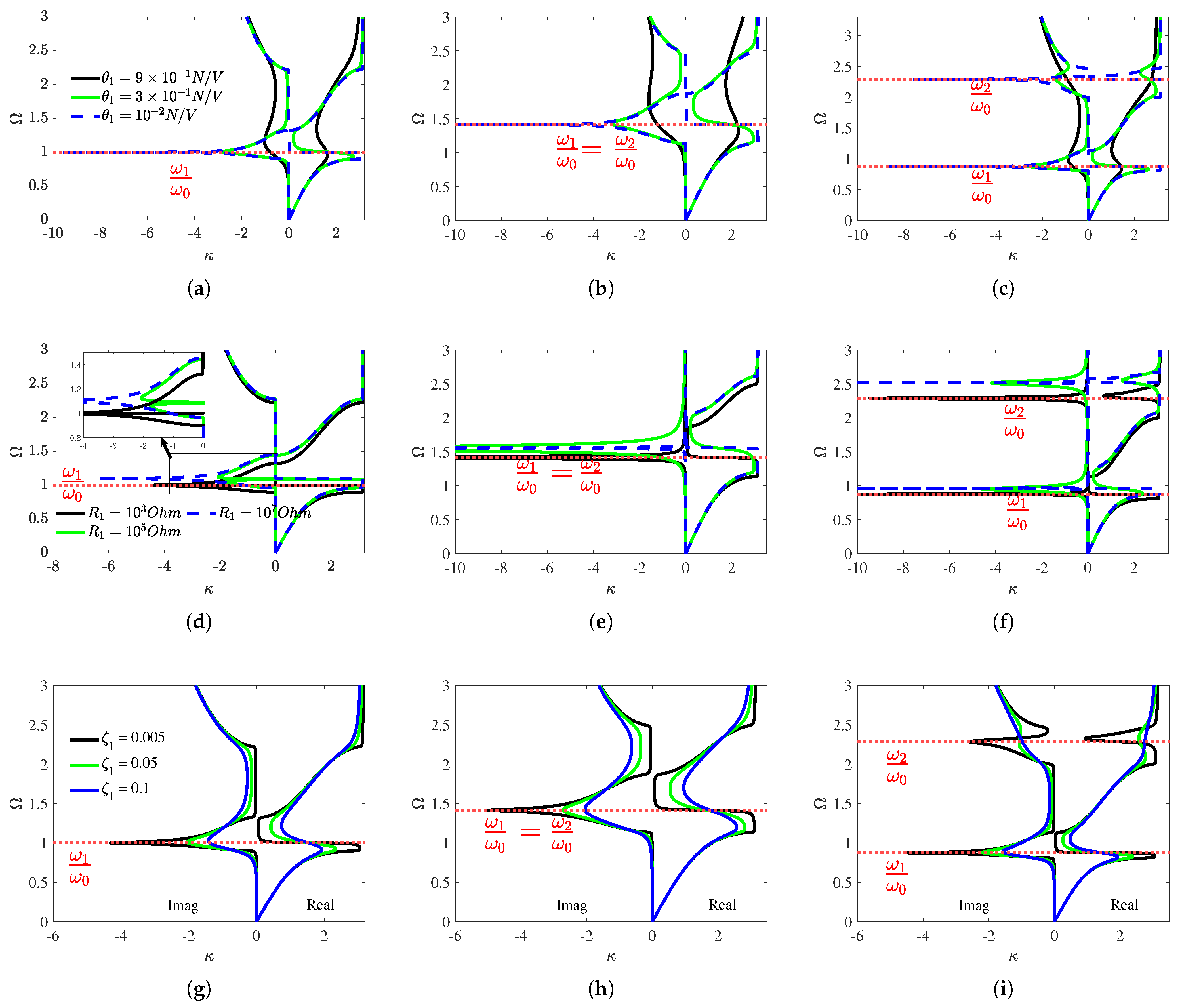
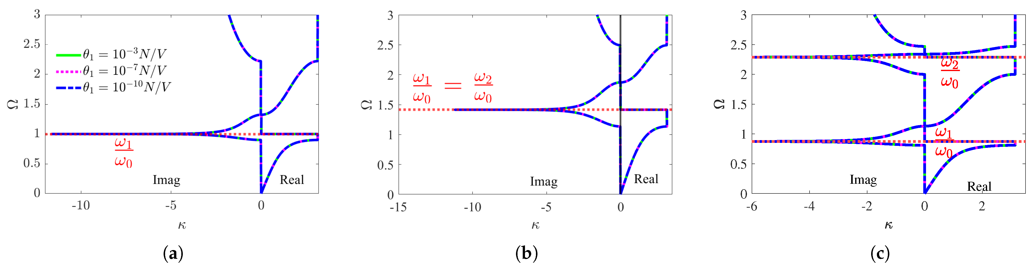
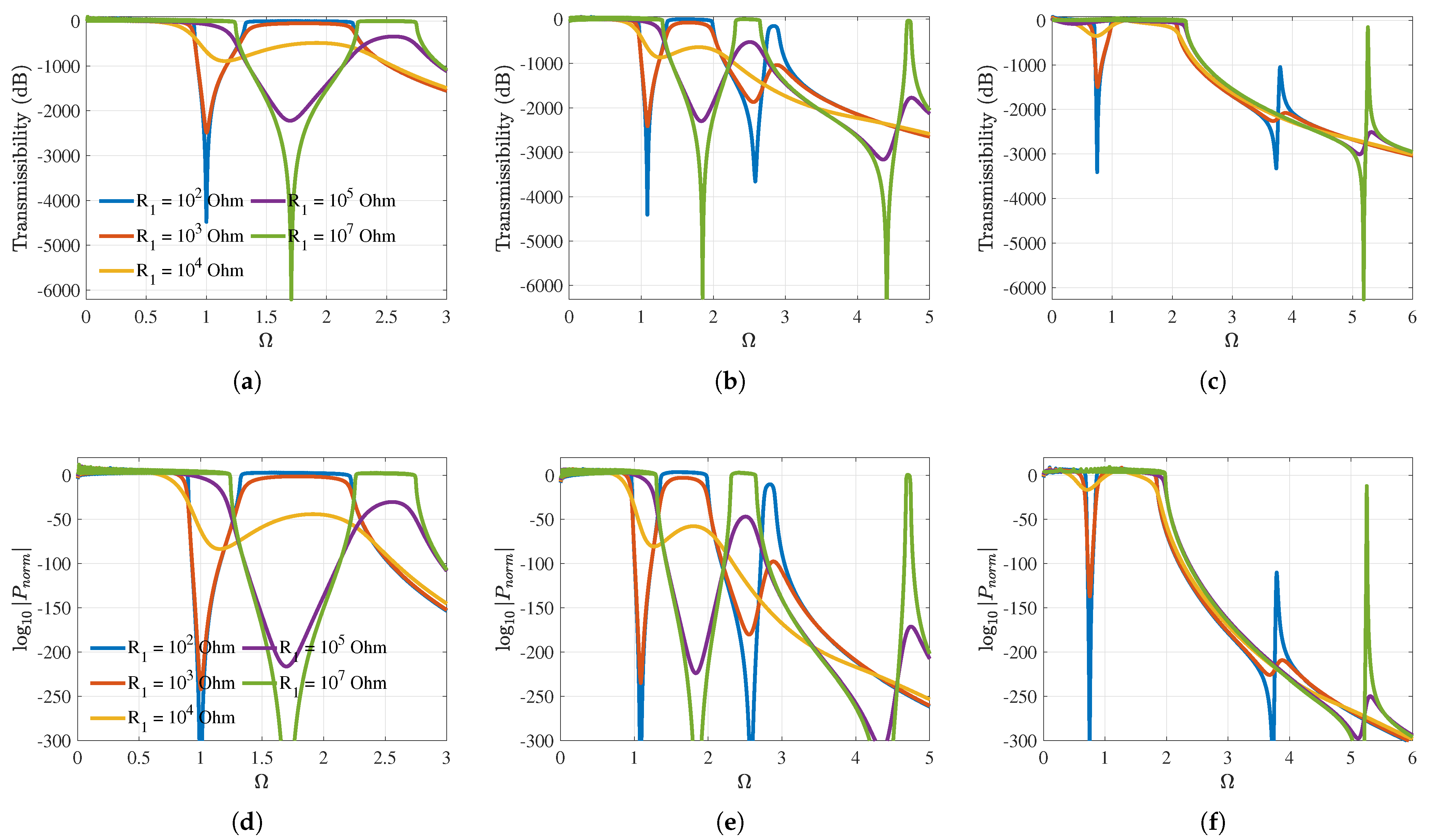
3.1. Effect of Electromechanical Coupling Coefficients and Shunt Circuit Resistances
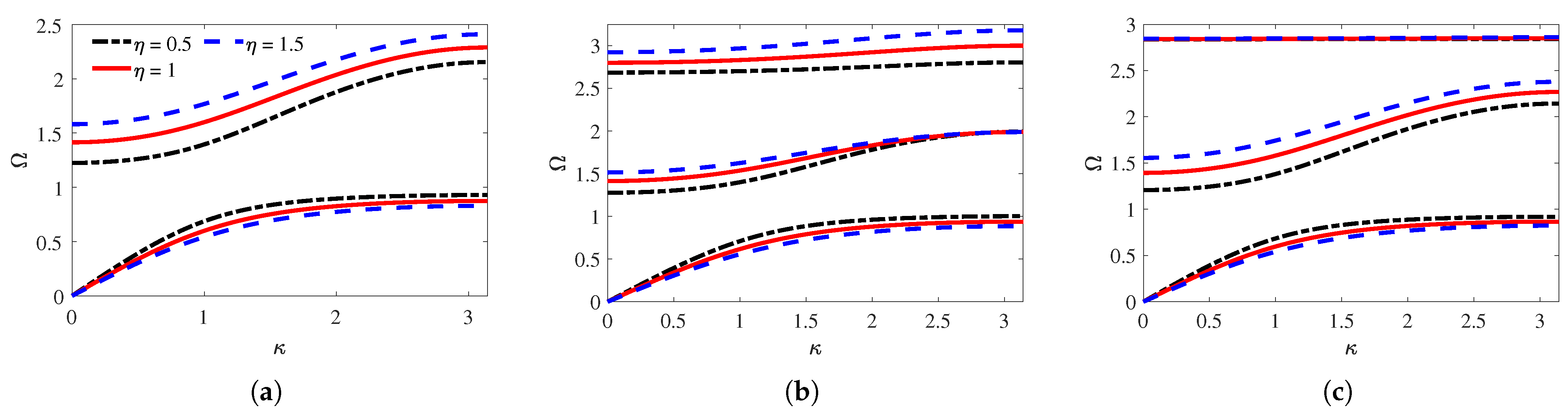
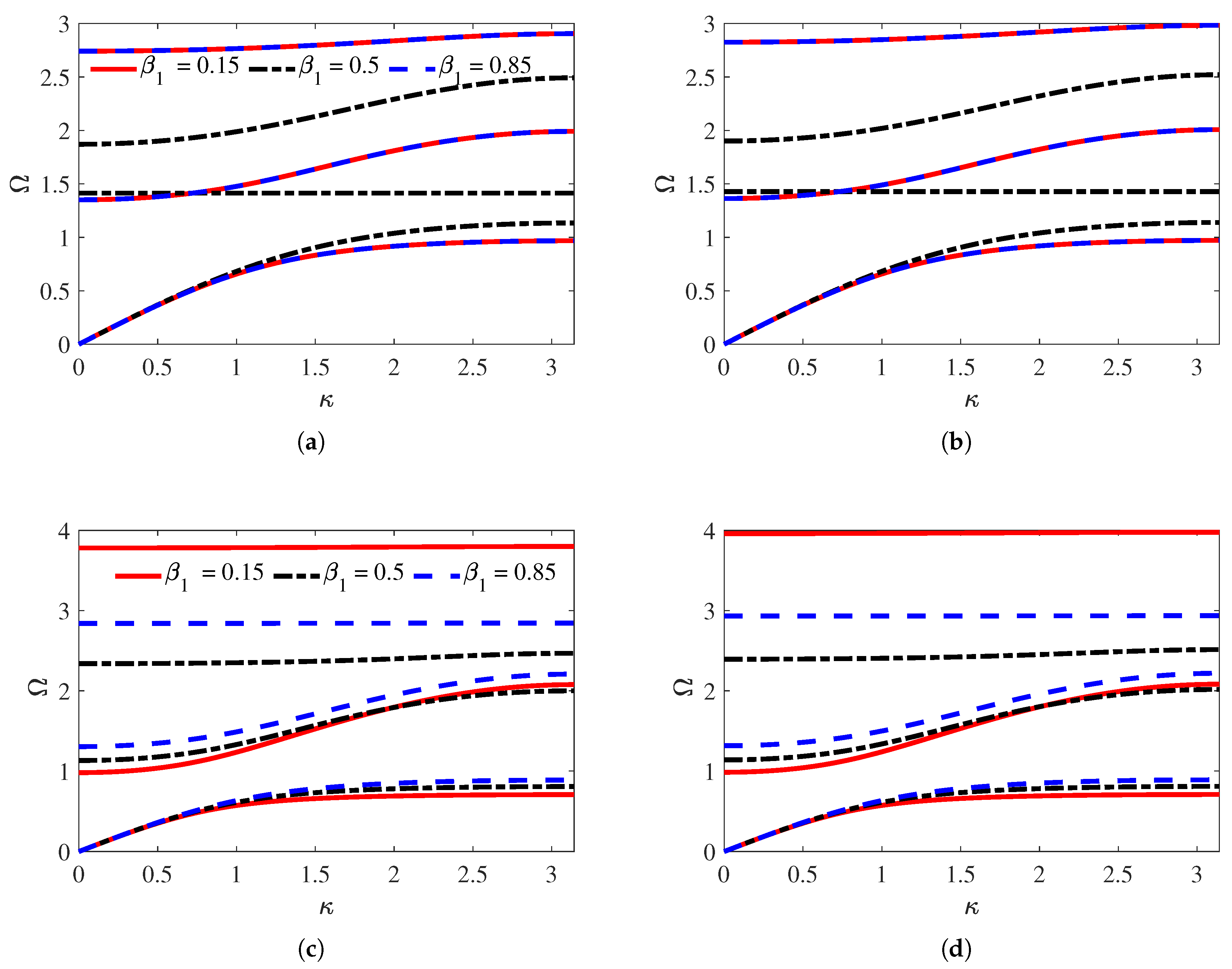
3.2. Effect of Resonator Mass Ratios
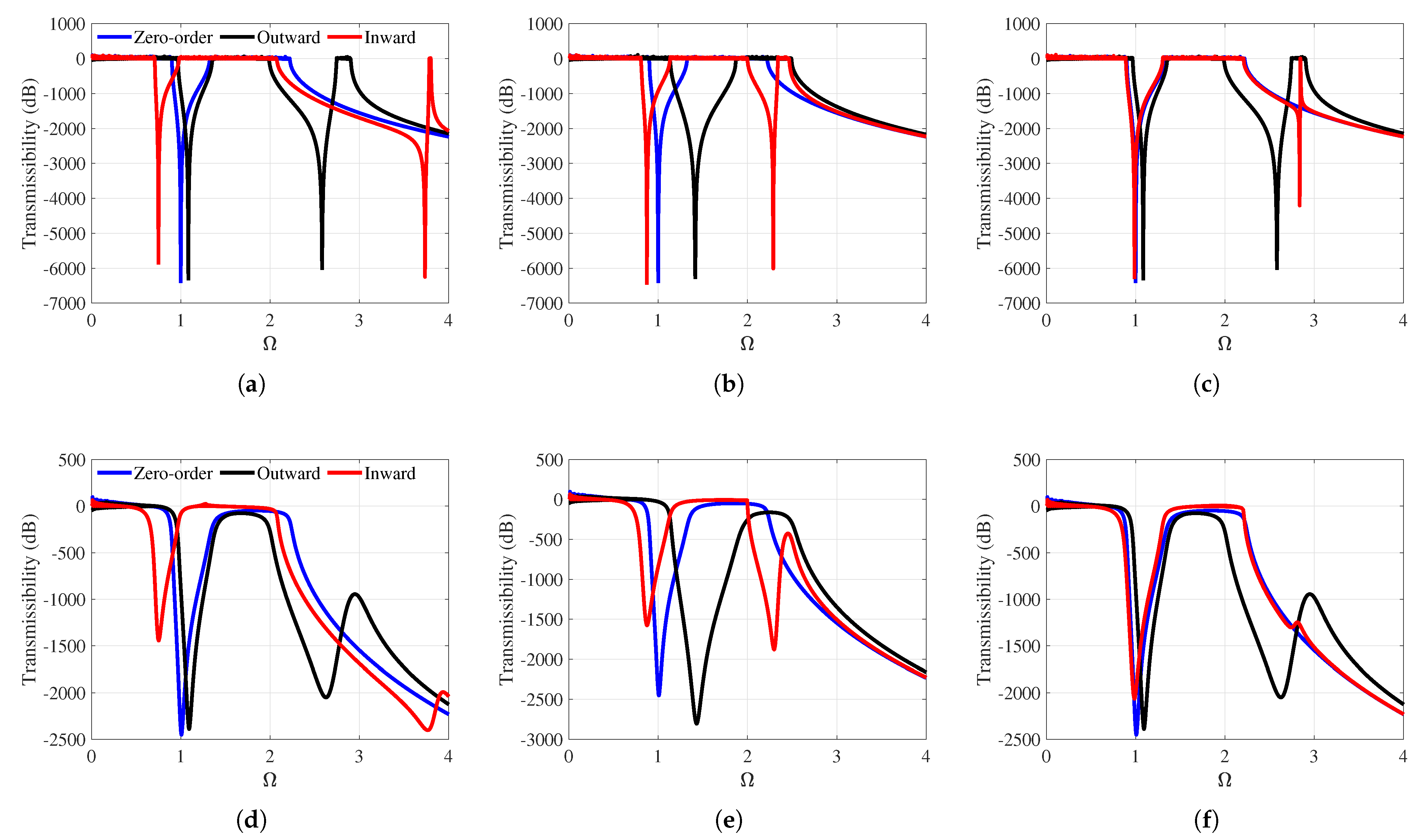
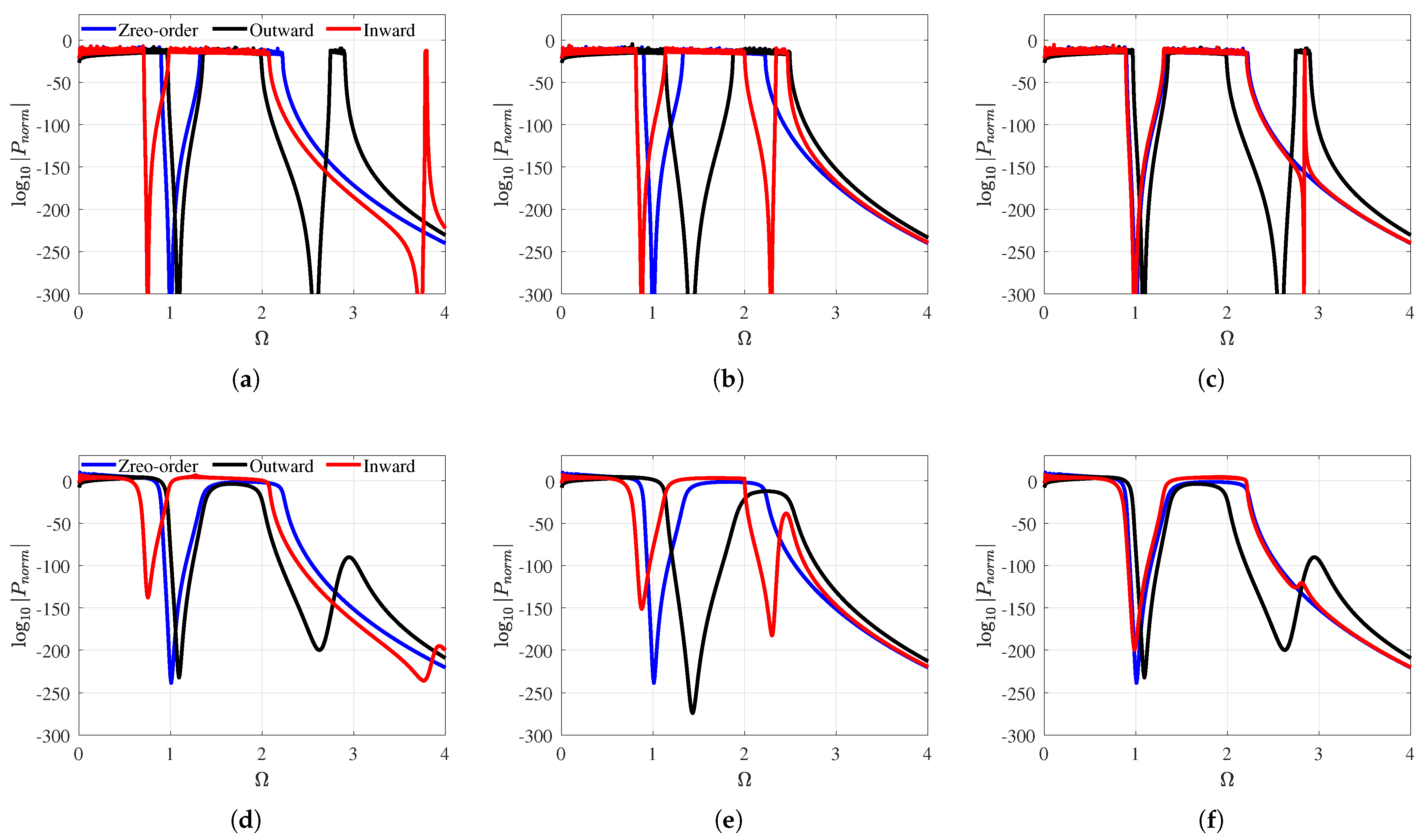
4. Transmissibility
5. Conclusions
Author Contributions
Funding
Institutional Review Board Statement
Informed Consent Statement
Data Availability Statement
Conflicts of Interest
Appendix A. The Determinant of The First-Order Outward and Inward Configurations
Appendix B. Mechanically Damped Resonators Equation of Motion
Appendix C. Transfer Functions T1 and T2, Calculation
References
- Lin, S.; Zhang, Y.; Liang, Y.; Liu, Y.; Liu, C.; Yang, Z. Bandgap characteristics and wave attenuation of metamaterials based on negative-stiffness dynamic vibration absorbers. J. Sound Vib. 2021, 502, 116088. [Google Scholar]
- Liu, Z.; Zhang, X.; Mao, Y.; Zhu, Y.; Yang, Z.; Chan, C.T.; Sheng, P. Locally resonant sonic materials. Science 2000, 289, 1734–1736. [Google Scholar]
- Lee, D.; Nguyen, D.M.; Rho, J. Acoustic wave science realized by metamaterials. Nano Converg. 2017, 4, 3. [Google Scholar]
- Meinzer, N.; Barnes, W.L.; Hooper, I.R. Plasmonic meta-atoms and metasurfaces. Nat. Photonics 2014, 8, 889–898. [Google Scholar]
- Cummer, S.A.; Christensen, J.; Alù, A. Controlling sound with acoustic metamaterials. Nat. Rev. Mater. 2016, 1, 16001. [Google Scholar]
- Ma, T.X.; Fan, Q.S.; Zhang, C.; Wang, Y.S. Acoustic flatbands in phononic crystal defect lattices. J. Appl. Phys. 2021, 129, 145104. [Google Scholar]
- Tol, S.; Degertekin, F.; Erturk, A. Gradient-index phononic crystal lens-based enhancement of elastic wave energy harvesting. Appl. Phys. Lett. 2016, 109, 063902. [Google Scholar] [CrossRef]
- Meng, Y.; Chen, Y.; Lu, L.; Ding, Y.; Cusano, A.; Fan, J.A.; Hu, Q.; Wang, K.; Xie, Z.; Liu, Z.; et al. Optical meta-waveguides for integrated photonics and beyond. Light. Sci. Appl. 2021, 10, 235. [Google Scholar]
- Li, W.; Cheng, S.; Yi, Z.; Zhang, H.; Song, Q.; Hao, Z.; Sun, T.; Wu, P.; Zeng, Q.; Raza, R. Advanced optical reinforcement materials based on three-dimensional four-way weaving structure and metasurface technology. Appl. Phys. Lett. 2025, 126, 033503. [Google Scholar]
- Hussein, M.I.; Leamy, M.J.; Ruzzene, M. Dynamics of phononic materials and structures: Historical origins, recent progress, and future outlook. Appl. Mech. Rev. 2014, 66, 040802. [Google Scholar]
- Hu, G.; Tang, L.; Das, R.; Gao, S.; Liu, H. Acoustic metamaterials with coupled local resonators for broadband vibration suppression. AIP Adv. 2017, 7, 025211. [Google Scholar] [CrossRef]
- Dwivedi, A.; Banerjee, A.; Adhikari, S.; Bhattacharya, B. Optimal electromechanical bandgaps in piezo-embedded mechanical metamaterials. Int. J. Mech. Mater. Des. 2021, 17, 419–439. [Google Scholar] [CrossRef]
- Fang, X.; Wen, J.; Bonello, B.; Yin, J.; Yu, D. Ultra-low and ultra-broad-band nonlinear acoustic metamaterials. Nat. Commun. 2017, 8, 1288. [Google Scholar] [PubMed]
- Yu, Z.; Li, M.; Xing, Z.; Gao, H.; Liu, Z.; Pu, S.; Mao, H.; Cai, H.; Ma, Q.; Ren, W.; et al. Genetic algorithm assisted meta-atom design for high-performance metasurface optics. Opto-Electron. Sci. 2024, 3, 240016. [Google Scholar] [CrossRef]
- Bukhari, M.; Barry, O. Broadband electromechanical diode: Acoustic non-reciprocity in weakly nonlinear metamaterials with electromechanical resonators. J. Vib. Acoust. 2023, 145, 021003. [Google Scholar]
- Contreras, N.; Zhang, X.; Hao, H.; Hernández, F. Application of elastic metamaterials/meta-structures in civil engineering: A review. Compos. Struct. 2023, 327, 117663. [Google Scholar] [CrossRef]
- Xiao, Y.; Wen, J.; Wen, X. Broadband locally resonant beams containing multiple periodic arrays of attached resonators. Phys. Lett. A 2012, 376, 1384–1390. [Google Scholar] [CrossRef]
- Kadic, M.; Bückmann, T.; Schittny, R.; Wegener, M. Metamaterials beyond electromagnetism. Rep. Prog. Phys. 2013, 76, 126501. [Google Scholar] [CrossRef]
- Yi, K.; Liu, Z.; Zhu, R. Multi-resonant metamaterials based on self-sensing piezoelectric patches and digital circuits for broadband isolation of elastic wave transmission. Smart Mater. Struct. 2021, 31, 015042. [Google Scholar]
- Cai, C.; Zhu, C.; Zhang, F.; Sun, J.; Wang, K.; Yan, B.; Zhou, J. Modeling and analysis of gradient metamaterials for broad fusion bandgaps. Appl. Math. Mech. 2024, 45, 1155–1170. [Google Scholar] [CrossRef]
- Liang, X.; Zhang, F.; Jiang, J. Ultra-wideband outward-hierarchical metamaterials with graded design. Int. J. Mech. Mater. Des. 2022, 18, 169–184. [Google Scholar]
- Zhao, B.; Thomsen, H.R.; De Ponti, J.M.; Riva, E.; Van Damme, B.; Bergamini, A.; Chatzi, E.; Colombi, A. A graded metamaterial for broadband and high-capability piezoelectric energy harvesting. Energy Convers. Manag. 2022, 269, 116056. [Google Scholar]
- Zhang, J.; Qian, D.h.; Ren, L.; Wang, Q. Electro-mechanical coupling properties of band gaps in an elastic/piezoelectric phononic crystal nonlocal nanobeam with periodically attached “spring-mass” resonators. Appl. Math.-A J. Chin. Univ. 2023, 38, 429–443. [Google Scholar]
- Xu, J.; Lu, H.; Qin, W.; Wang, P.; Bian, J. Mechanical shunt resonators-based piezoelectric metamaterial for elastic wave attenuation. Materials 2022, 15, 891. [Google Scholar] [CrossRef]
- Xu, X.; Barnhart, M.V.; Li, X.; Chen, Y.; Huang, G. Tailoring vibration suppression bands with hierarchical metamaterials containing local resonators. J. Sound Vib. 2019, 442, 237–248. [Google Scholar] [CrossRef]
- Li, Q.; He, Z.; Li, E.; Cheng, A. Design of a multi-resonator metamaterial for mitigating impact force. J. Appl. Phys. 2019, 125, 035104. [Google Scholar]
- Huang, G.; Sun, C. Band gaps in a multiresonator acoustic metamaterial. J. Vib. Acoust. 2010, 132, 031003. [Google Scholar]
- Zhao, P.; Zhang, K.; Zhao, C.; Deng, Z. Multi-resonator coupled metamaterials for broadband vibration suppression. Appl. Math. Mech. 2021, 42, 53–64. [Google Scholar]
- Gorshkov, V.; Sareh, P.; Navadeh, N.; Tereshchuk, V.; Fallah, A.S. Multi-resonator metamaterials as multi-band metastructures. Mater. Des. 2021, 202, 109522. [Google Scholar]
- Zhou, J.; Wang, K.; Xu, D.; Ouyang, H. Multi-low-frequency flexural wave attenuation in Euler–Bernoulli beams using local resonators containing negative-stiffness mechanisms. Phys. Lett. A 2017, 381, 3141–3148. [Google Scholar]
- Zhao, J.; Zhou, H.; Yi, K.; Kovacic, I.; Zhu, R. Ultra-broad bandgap induced by hybrid hardening and softening nonlinearity in metastructure. Nonlinear Dyn. 2023, 111, 17687–17707. [Google Scholar] [CrossRef]
- Mork, N.; Fronk, M.D.; Sinclair, M.B.; Leamy, M.J. Nonlinear hierarchical unit cell for passive, amplitude-dependent filtering of acoustic waves. Extrem. Mech. Lett. 2022, 57, 101915. [Google Scholar] [CrossRef]
- Mork, N.; Fronk, M.D.; Biedermann, L.B.; Sinclair, M.B.; Leamy, M.J. Hierarchical unit cell employing a nonlinear energy sink for passive, low-pass amplitude filtering of acoustic waves. Extrem. Mech. Lett. 2023, 63, 102056. [Google Scholar] [CrossRef]
- Chen, J.; Li, J.; Yao, M.; Liu, J.; Zhang, J.; Sun, M. Nonreciprocity of energy transfer in a nonlinear asymmetric oscillator system with various vibration states. Appl. Math. Mech. 2023, 44, 727–744. [Google Scholar] [CrossRef]
- Wang, C.; Moore, K.J. On nonlinear energy flows in nonlinearly coupled oscillators with equal mass. Nonlinear Dyn. 2021, 103, 343–366. [Google Scholar] [CrossRef]
- Fronk, M.D.; Tawfick, S.; Daraio, C.; Li, S.; Vakakis, A.; Leamy, M.J. Acoustic non-reciprocity in lattices with nonlinearity, internal hierarchy, and asymmetry: Computational study. J. Vib. Acoust. 2019, 141, 051011. [Google Scholar] [CrossRef]
- Huang, H.H.; Sun, C.T.; Huang, G. On the negative effective mass density in acoustic metamaterials. Int. J. Eng. Sci. 2009, 47, 610–617. [Google Scholar] [CrossRef]
- Sugino, C.; Ruzzene, M.; Erturk, A. Nonreciprocal piezoelectric metamaterial framework and circuit strategies. Phys. Rev. B 2020, 102, 014304. [Google Scholar] [CrossRef]
- Hu, G.; Tang, L.; Banerjee, A.; Das, R. Metastructure with piezoelectric element for simultaneous vibration suppression and energy harvesting. J. Vib. Acoust. 2017, 139, 011012. [Google Scholar] [CrossRef]
- Sugino, C.; Leadenham, S.; Ruzzene, M.; Erturk, A. An investigation of electroelastic bandgap formation in locally resonant piezoelectric metastructures. Smart Mater. Struct. 2017, 26, 055029. [Google Scholar] [CrossRef]
- Tang, J.; Wang, K. Vibration control of rotationally periodic structures using passive piezoelectric shunt networks and active compensation. J. Vib. Acoust. 1999, 121, 379–390. [Google Scholar]
- Tang, J.; Wang, K.W. Active-passive hybrid piezoelectric networks for vibration control: Comparisons and improvement. Smart Mater. Struct. 2001, 10, 794. [Google Scholar]
- Thorp, O.; Ruzzene, M.; Baz, A. Attenuation and localization of wave propagation in rods with periodic shunted piezoelectric patches. Smart Mater. Struct. 2001, 10, 979. [Google Scholar] [CrossRef]
- Casadei, F.; Ruzzene, M.; Dozio, L.; Cunefare, K. Broadband vibration control through periodic arrays of resonant shunts: Experimental investigation on plates. Smart Mater. Struct. 2009, 19, 015002. [Google Scholar] [CrossRef]
- Yan, Z.; Tran, H.; Ma, D.; Xie, J. Emerging Piezoelectric Metamaterials for Biomedical Applications. Mater. Interfaces 2024, 1, 13–34. [Google Scholar] [CrossRef]
- Valipour, A.; Kargozarfard, M.H.; Rakhshi, M.; Yaghootian, A.; Sedighi, H.M. Metamaterials and their applications: An overview. Proc. Inst. Mech. Eng. Part L J. Mater. Des. Appl. 2022, 236, 2171–2210. [Google Scholar]
- Bukhari, M.A.; Qian, F.; Barry, O.R.; Zuo, L. Effect of electromechanical coupling on locally resonant metastructures for simultaneous energy harvesting and vibration attenuation applications. In Proceedings of the Dynamic Systems and Control Conference, Online, 5–7 October 2020; American Society of Mechanical Engineers: New York, NY, USA, 2020; Volume 84287, p. V002T38A003. [Google Scholar]
- LeGrande, J.; Bukhari, M.; Barry, O. Effect of electromechanical coupling on locally resonant quasiperiodic metamaterials. AIP Adv. 2023, 13, 015112. [Google Scholar]
- Malla, A.; Bukhari, M.; Barry, O. Modeling and Analysis of a Nonlinear Locally Resonant Metamaterial with Inductance Shunt. In Earth and Space 2022; ASCE Press: Reston, VA, USA, 2022; pp. 504–515. [Google Scholar]
- Bukhari, M.; Barry, O. Simultaneous energy harvesting and vibration control in a nonlinear metastructure: A spectro-spatial analysis. J. Sound Vib. 2020, 473, 115215. [Google Scholar]
- Malla, A.; Bukhari, M.; Barry, O. On a nonlinear locally resonant metamaterial with resistance-inductance shunt. J. Comput. Nonlinear Dyn. 2024, 19, 051007. [Google Scholar] [CrossRef]
- Tang, L.; Yang, Y. A multiple-degree-of-freedom piezoelectric energy harvesting model. J. Intell. Mater. Syst. Struct. 2012, 23, 1631–1647. [Google Scholar] [CrossRef]
- Gao, Y.; Wang, L.; Sun, W.; Wu, K.; Hu, H. Ultrawide bandgap in metamaterials via coupling of locally resonant and Bragg bandgaps. Acta Mech. 2022, 233, 477–493. [Google Scholar]
- Phani, A.S.; Woodhouse, J.; Fleck, N. Wave propagation in two-dimensional periodic lattices. J. Acoust. Soc. Am. 2006, 119, 1995–2005. [Google Scholar] [PubMed]
- Shu, Y.; Lien, I. Analysis of power output for piezoelectric energy harvesting systems. Smart Mater. Struct. 2006, 15, 1499. [Google Scholar]
- Stein, A.; Nouh, M.; Singh, T. Widening, transition and coalescence of local resonance band gaps in multi-resonator acoustic metamaterials: From unit cells to finite chains. J. Sound Vib. 2022, 523, 116716. [Google Scholar]
- Wang, X. A study of harvested power and energy harvesting efficiency using frequency response analyses of power variables. Mech. Syst. Signal Process. 2019, 133, 106277. [Google Scholar]


| Properties | , | ||
|---|---|---|---|
| Value | kg | rad/s | F |
| Parameter | Effect on Vibration Attenuation | Effect on Energy Harvesting | Remarks |
|---|---|---|---|
| Strong Electromechanical Coupling | |||
| and | Increase in band gap width, mode merging, and reduction in resonance peaks. | Power output increases with and . | This is critical for optimizing dual functionality. |
| and | For lower frequency attenuation, smaller and values are preferred, for higher frequency and stronger attenuation, higher and values. | Between and ohms results in power output with minimal drop. | Higher frequency passbands are predominantly impacted. |
| Smaller or higher creates broad band gap, which is desirable for vibration attenuation. | Power output in the third passband decreases as deviates farther from . | It affects performance based on configuration type. | |
| Weak Electromechanical Coupling | |||
| and | Minimal effect. | Increasing and raises the local power output peaks. | Less effective for attenuating vibrations. |
| and | Minimal effect. | Increases the local peaks of the power output. | Resistance mainly influences energy harvesting. |
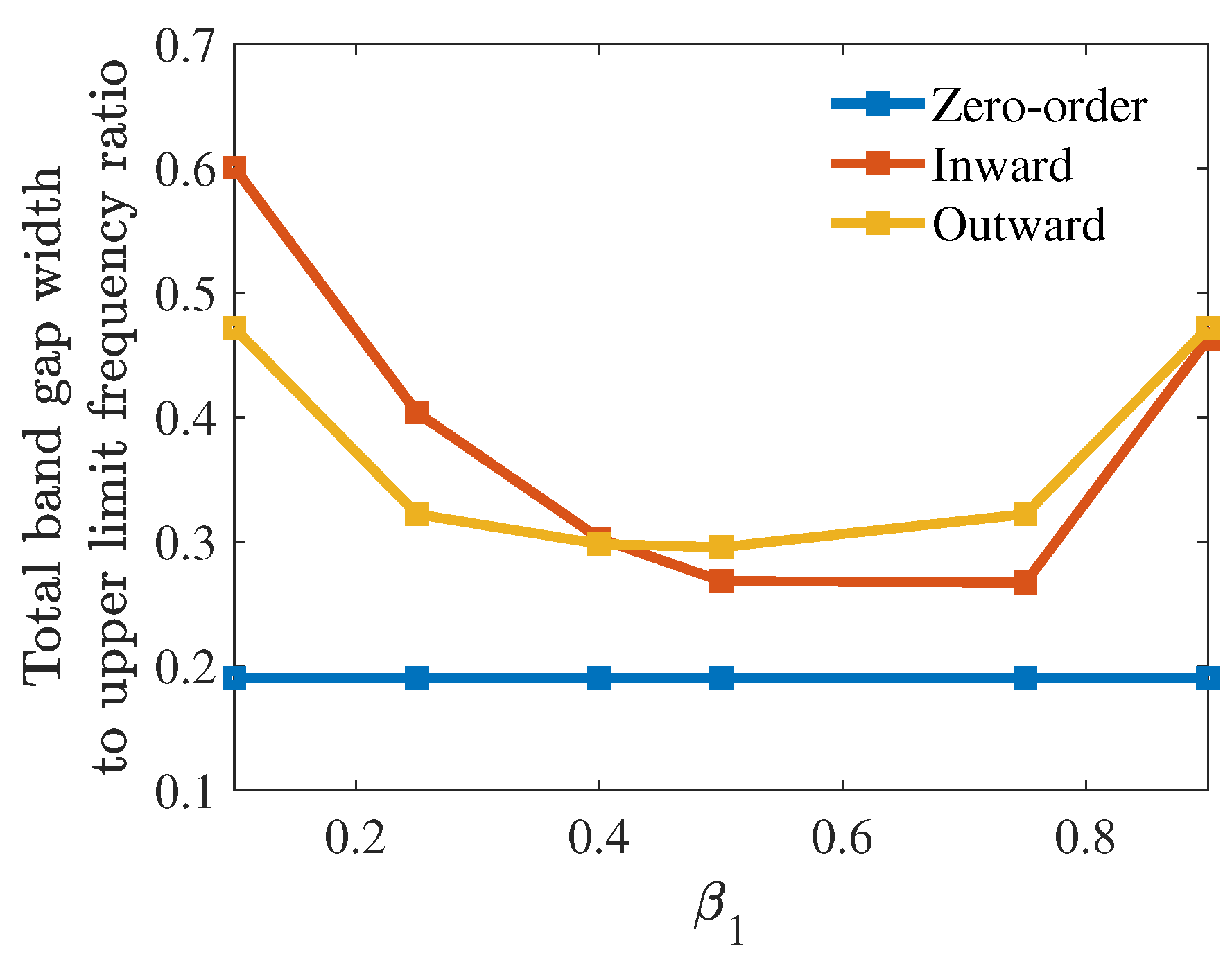
| As moves farther from 0.5, the vibration attenuation spectrum increases. The inward configuration suppresses lower frequency vibrations. | Power can be harvested across a broad frequency range by varying . | It offers tunability for specific applications depending on configuration type. | |
Disclaimer/Publisher’s Note: The statements, opinions and data contained in all publications are solely those of the individual author(s) and contributor(s) and not of MDPI and/or the editor(s). MDPI and/or the editor(s) disclaim responsibility for any injury to people or property resulting from any ideas, methods, instructions or products referred to in the content. |
© 2025 by the authors. Licensee MDPI, Basel, Switzerland. This article is an open access article distributed under the terms and conditions of the Creative Commons Attribution (CC BY) license (https://creativecommons.org/licenses/by/4.0/).
Share and Cite
Mebrat, A.A.; LeGrande, J.; Barry, O. Analytical Investigation of Electromechanical Hierarchical Metamaterials for Vibration Attenuation and Energy Harvesting. Appl. Sci. 2025, 15, 3464. https://doi.org/10.3390/app15073464
Mebrat AA, LeGrande J, Barry O. Analytical Investigation of Electromechanical Hierarchical Metamaterials for Vibration Attenuation and Energy Harvesting. Applied Sciences. 2025; 15(7):3464. https://doi.org/10.3390/app15073464
Chicago/Turabian StyleMebrat, Ashenafi Abebe, Joshua LeGrande, and Oumar Barry. 2025. "Analytical Investigation of Electromechanical Hierarchical Metamaterials for Vibration Attenuation and Energy Harvesting" Applied Sciences 15, no. 7: 3464. https://doi.org/10.3390/app15073464
APA StyleMebrat, A. A., LeGrande, J., & Barry, O. (2025). Analytical Investigation of Electromechanical Hierarchical Metamaterials for Vibration Attenuation and Energy Harvesting. Applied Sciences, 15(7), 3464. https://doi.org/10.3390/app15073464