Article

Solar Irradiance Mitigation in LEO Optical Inter-Satellite Links via Inter-Shell Based Path Optimization

Department of Information and Telecommunication Engineering, Incheon National University, Incheon 22012, Republic of Korea
*
Author to whom correspondence should be addressed.
Appl. Sci. 2025, 15(6), 3364; https://doi.org/10.3390/app15063364
Submission received: 19 January 2025 / Revised: 4 March 2025 / Accepted: 15 March 2025 / Published: 19 March 2025
(This article belongs to the Section Aerospace Science and Engineering)

Abstract

:
Solar irradiance is a critical factor influencing the reliability of optical inter-satellite links (O-ISLs). Despite its significance, limited research has focused on addressing this challenge. This work investigates the impact of solar irradiation on the optimal path configuration. A multi-directional field-of-view (FoV) model is used to practically accommodate the solar irradiance imposed on each optical transceiver module in a single satellite. The effectiveness of the optimal path configurations is evaluated through detour mitigation strategies, comparing inter-plane and inter-shell link alternatives in intercontinental scenarios within the northern hemisphere. In the scenarios, it is found that there is a tradeoff between the FoV and the level of the signal-to-noise ratio (SNR) required to overcome the effects of solar irradiance. Also, seasonal alterations in the sun’s incident direction significantly influence the link availability, with unusable link rates nearly doubling in summer compared to spring because of orbital inclinations tending to be aligned more closely with the solar direction toward Earth. The proposed inter-shell-based path optimization reduces the total link distance by up to 2500 km compared to those of the inter-plane configurations, demonstrating superior performance in mitigating impairment due to solar irradiance.

1. Introduction

The development of next-generation wireless communication systems has increased interest in satellite communication systems. It aims to achieve ambitious goals, such as providing universal connectivity to reduce the gap in the connectivity, offering coverage anywhere and anytime, improving reliability, and promoting sustainability. It also aims to deliver much faster data speeds and lower latency compared to those of current technologies. Achieving these goals requires advancements not only in communication technologies but also in improving the user experience, often referred to as quality of service (QoS) [1].
These requirements have caused a rapid increase in network connections, making it hard for terrestrial networks alone to handle the growing demand efficiently. As a result, integrating terrestrial networks with non-terrestrial networks (NTNs), like satellite systems, is becoming essential to meet these needs in a cost-effective way. Satellite communication in space, especially using inter-satellite links (ISLs), offers unique benefits over ground-based networks and has attracted significant interest. ISLs can act as space-based base stations, helping to ensure high QoSs for users [1,2].
ISLs are categorized based on orbital height, with low-Earth orbit (LEO) being one of the key classifications. Positioned at altitudes ranging from 350 to 2000 km, LEO constellations are actively being developed by various companies and organizations. The low altitude of LEO provides distinct advantages, including shorter propagation distances and latency, reduced energy requirements for satellite launches, and cost efficiency. The advent of reusable launch systems has also drastically reduced overall costs [3].
The transition to next-generation communications introduces unprecedented demand for connectivity, driven by emerging applications, such as augmented reality (AR), virtual reality (VR), autonomous systems, and the advanced Internet-of-Things (IoT) network. The third-generation partnership project (3GPP) also explores methods to align ISLs with requirements. One promising approach involves optical inter-satellite links (O-ISLs), which leverage optical wireless communications (OWCs) for satellite communications. O-ISLs, using free-space optic (FSO) technologies, offer numerous advantages, including high channel capacities, secure data transmission, rapid data rates, immunity to electromagnetic and radio frequency interference, and low beam divergence [4,5]. Compared to traditional radio-frequency (RF) systems, O-ISLs exhibit superior economic and spatial efficiencies because of compact antenna sizes, reduced signal power loss resulting from shorter wavelengths (approximately 1000 times shorter than microwaves), and cost advantages. Small satellites, crucial to O-ISL systems, are considerably more economical to deploy than their full-sized counterparts. O-ISLs also support high data rates of up to 2.5 Gb/s, and propagation distances exceeding 5000 km, with freedom from frequency regulation constraints [6,7].
Despite these advantages, several factors disrupt optical signals in O-ISLs. Solar irradiance can be a primary source of such interference. Although sunlight is attenuated on the surface of the Earth through the atmosphere, satellites’ optical receivers in space are directly exposed to intense solar radiation, potentially affecting O-ISL performances. To address these challenges, this work presents a systematic analysis of the effects of solar irradiance on O-ISLs. A multi-directional field-of-view (FoV) model and a communication environmental analysis framework proposed in reference [8] are applied in this work. This model is designed to flexibly incorporate practical factors, such as multiple optical modules, FoVs, beam divergence, maximum laser propagation distance, and altitude constraints. More importantly, using an ego-centric coordinate system, the model allows for geometrical investigations based on the satellite’s orientation and position at a user-specified time. Therefore, this model is suitable for the study of relative-location-based solar irradiation.
This research is motivated by the necessity for understanding and mitigating the effects of solar irradiance on O-ISLs, particularly in the context of satellite’s mega-constellations. This work presents three key contributions: (i) a systematic methodology for assessing the impact of solar irradiance on O-ISLs, integrating practical parameters, such as the receiver’s FoV (at both the azimuth and elevation angles), directionality, transmission power, and noise characteristics; (ii) a detailed analysis of how solar irradiance affects O-ISL performance in mega-satellite constellations, incorporating seasonal and statistical evaluations to capture real-world variability; and (iii) an investigation into the benefits of inter-shell O-ISL configurations for path optimization under solar interference, supported by verifications using intercontinental O-ISL scenarios. By providing these insights, this work aims to enhance the design and operational planning of O-ISLs, contributing to more resilient and efficient inter-satellite communication networks. Section 2 discusses the system modeling framework for evaluating solar irradiance’s impact on LEO O-ISLs, presenting a multi-directional FoV model and theoretical approaches, such as Heron’s law and signal-to-noise-ratio (SNR) analysis. Section 3 outlines the simulation results, with performance comparisons between inter-plane and inter-shell setups under various seasonal and geographical conditions, followed by Section 4, with a discussion and conclusions.

2. System Modeling

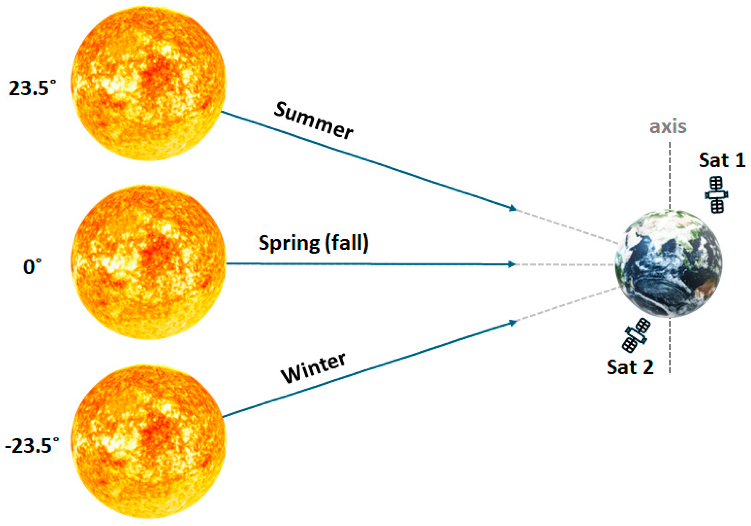
2.1. Solar Irradiance: Theoretical Approach

Configuring the optimal path for O-ISLs involves extensive calculations, and considering all the satellites in a constellation can significantly increase the model’s complexity. To reduce the computational load, this study proposes an approach to classify satellites affected by solar irradiance from those unaffected. Conventionally, the region on Earth illuminated by sunlight is referred to as half the surface of the Earth. However, sunlight can extend beyond the half, particularly as satellites operate hundreds of kilometers above the ground. To address this, Equations (1) and (2) are introduced as follows:
p p d s u n p r s r E p d m a x   = 1 2 × d m a x × r E
p = 1 2 r s + r E + d s u n + d m a x .
These equations numerically derive d m a x , the maximum distance sunlight can reach, accounting for a satellite’s altitude. The area of a triangle can be determined using Heron’s law, which defines it in terms of the semi-perimeter ( p ), and d m a x is calculated by equating Heron’s law with the typical triangle area formula. For this, the triangle is formed by the satellite’s altitude ( r s   ) plus Earth’s radius ( r s ), the distance from the satellite to the sun ( d m a x ), and the Earth–sun distance ( d s u n ). Figure 1 illustrates this approach, and the results are shown in Figure 2. As shown in Figure 2a, representing spring and fall, and Figure 2b, representing summer, the illuminated region varies by season. The altitudes of the five shells in the inter-shell of the Starlink’s satellite constellation, detailed in Section 2.3, are 540 km, 550 km, 560 km, and 570 km. The gaps between d m a x and 1 AU are confirmed as 2678 km, 2704 km, 2729 km, and 2755 km, respectively. This analysis validates that the illuminated area encompassing the satellites (yellow) is larger than the region that covers half the Earth (orange).
To optimize O-ISL paths under solar irradiance, interference effects must be accurately identified. There are corresponding scenarios to occur, including (i) the receiver operating successfully despite the solar illumination and (ii) the receiver being affected and avoiding the affected nodes.
To simulate the interference effects, an SNR analysis is applied, considering the typical wavelength range used in O-ISLs. The simulation incorporates practical components, such as avalanche photodiodes (APDs) [9] and lasers [10], which focus on performance at 1550 nm. The background current ( I b ), caused by sunlight, is defined as follows [11]:
I b = A d M F o V 1000 1700 P D S λ R λ T s i g λ d λ ,
where P D S is the solar irradiance ( W / m 2 / nm ), R is the responsivity ( A / W ), A d is the APD’s aperture ( mm 2 ), and T s i g is the bandpass filter coefficient. The transmitted signal current ( I x ) is defined as follows:
I x = m + 1 A d M F o V 2 π d 2 1000 1700 P T L λ R λ T s i g λ d λ ,
where m is the Lambertian order, d is the typical O-ISL laser propagation distance (km), and P T L λ is the transmission power as follows:
P T L λ = P M a x L λ P L λ 1000 1700 P L λ d λ ,
where P M a x L λ is the maximum transmission power, and P L λ is the wavelength-specific power distribution. The signal and noise parameters, including the shot noise ( σ s 2 ), dark noise ( σ d 2 ), and thermal noise ( σ T 2 ), incorporate the gain from the FoV ( M F o V ) as follows:
M F o V = 1.5 2 sin 2 θ F o V
σ s 2 = 2 q M A P D 2 F I b + I x B
σ x 2 = 2 q M A P D 2 F I x B
σ d 2 = 2 q F I d g B + 2 q I d s B
σ T 2 = 4 K B T R L B ,
where θ F o V is the field of view ( ° ), M A P D is the APD’s gain, q is the electron’s charge, B is the APD’s bandwidth (Hz), F is the excess noise, I d g is the surface’s dark current, I d s is the bulk’s dark current, K B is Boltzmann’s constant, T is the temperature (K), and R L is the load’s resistance (Ω). In this simulation, the 50 Ω load resistor is chosen for its standard use in high-frequency systems, ensuring impedance matching and signal integrity at the gigahertz range of operation without compromising the analysis dominated by the shot noise in the system’s framework. On the other hand, the signal-to-noise ratio (SNR, γ ) is defined as follows:
γ = I x 2 σ n 2 / H k 2 ,  
where σ n 2 , the noise variance, varies, depending on sunlight’s presence, as follows:
σ n 2 = σ x 2 + σ d 2 + σ T 2 ,     w / o   s u n σ s 2 + σ d 2 + σ T 2 ,     w /       s u n .
This study assumes H k , the channel response, does not affect signals, focusing instead on solar interference effects.

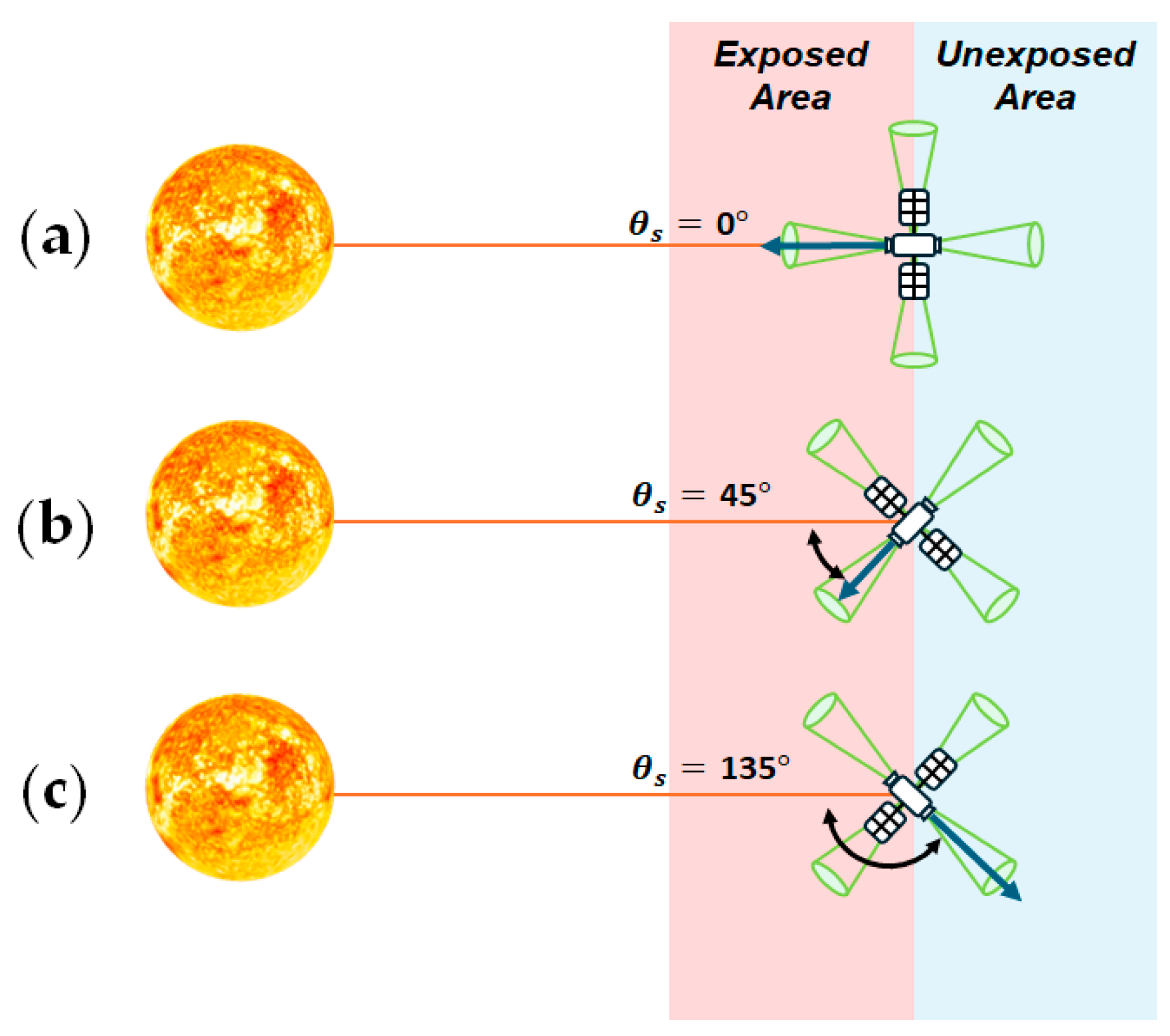
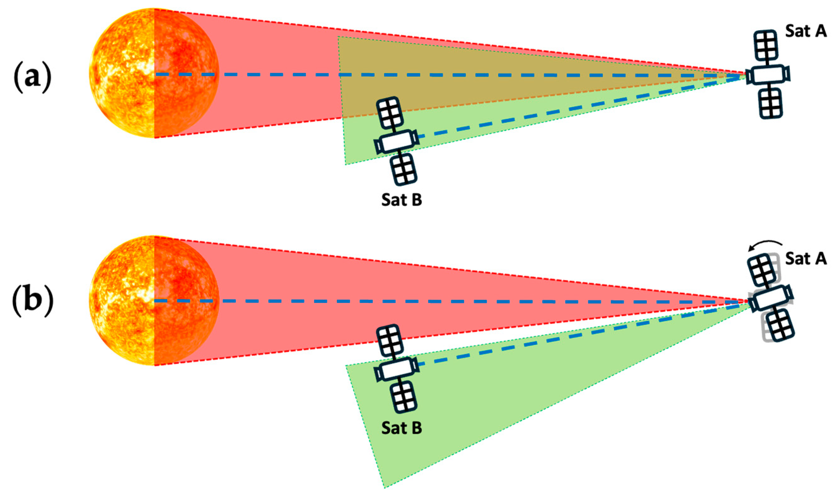
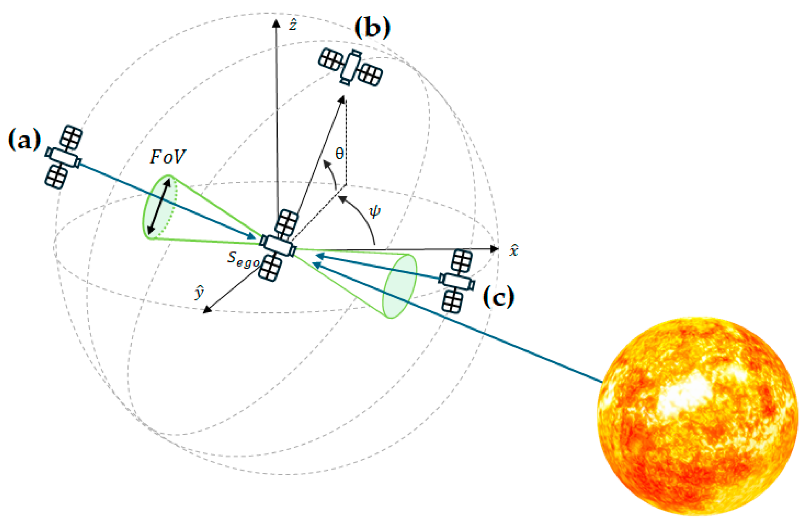
2.2. Individual-Satellite-Oriented Multi-Directional FoV

A previous study [12] incorporates the elevation angle of the sun ( θ s ) to model solar power impacting satellites. Specifically, when θ s is between 0° and 90°, the sunlight affects the optical link based on incident angle, accordingly, while it is set at zero for all the other angles. Because the effect of the solar irradiance depends on the alignment among the sun, transmitter, and receiver, it is critical to evaluate the overall irradiance on individual satellites according to the relative position of each.
From a practical perspective, the focus should shift to determine which receiver is affected by sunlight rather than evaluating the satellite body as a whole. This is particularly relevant for O-ISL configurations, where satellites typically host multiple transceiver terminals [13,14,15]. For single-transceiver systems, the elevation angle of the sun ( θ s ) is a critical factor. However, in systems employing multiple transceivers, the narrow-beam nature of optical communications necessitates evaluating whether solar light enters the FoV of each receiver.
A multi-directional FoV model enables the simultaneous assessment of the FoVs of individual receivers in various directions. Figure 3 illustrates a satellite equipped with four optical modules, showing the feasibility of diverse optical link configurations. Depending on the position of the sun, each receiver is affected by different levels of solar interference. In unexposed areas, no module is affected by solar irradiance. In contrast, exposed areas, such as those in Figure 3a, reveal situations where certain modules are affected by solar interference. Meanwhile, other modules can maintain communication despite solar irradiance, as demonstrated in Figure 3b,c. These observations emphasize the importance of individually analyzing solar irradiance constraints for each receiver.
The solar power decision range is confined to a maximum of 90°, which means that the half FoV of the receiver is limited to 45°. This range can significantly reduce the performance of O-ISLs. A wider FoV, although enabling broader coverage, increases the signal interference, reduces the received signals’ strength (RSS), and causes additional costs because of the need for extra modules.
Previous research [16] has identified the threshold angle for the optical link connectivity affected by solar interference, termed as the outage angle, as 3°. This angle is determined by the vectors between the satellite-to-sun and satellite-to-adjacent satellite links. The outage angles could differ, especially for complex O-ISL configurations, where orientational parameters come into play. In addition to these analyses, Table 1 is provided to compare the overall investigation coverages of the simulation in our work with those in previous studies.
As illustrated in Figure 4, the practical outage angle depends on the relative rotation of the satellite. In situation (a), the FoV from satellite A to satellite B, represented by the green dotted area, overlaps with that from satellite A to the sun, deteriorating the communication performance. However, in situation (b), although the relative positions are precisely the same, the slight rotation of satellite A makes the communication link unaffected by the solar light. This demonstrates the need for a dynamic outage angle that adapts to real-time orbital positions and satellite orientations. The dynamic nature of satellites orbiting Earth, with three-dimensional calculations, is required to implement a simulator capable for identifying solar interference and optimizing the overall path configuration. Moreover, the axial tilt and seasonal changes of the Earth should be considered.
As shown in Figure 5, the axis of Earth’s rotation changes depending on the season, affecting the sun’s irradiation angles to the satellites as well. This seasonal variation is modeled using inclination angles of 0° for fall, 23.5° for summer, and −23.5° for winter (considering the northern hemisphere). The location of the sun is determined using azimuth and elevation angles, represented as follows:
ψ s u n = v e · t
x s u n = d s u n · cos θ s u n · s i n ψ s u n y s u n = d s u n · c o s θ s u n z s u n = d s u n · s i n θ s u n ,
where θ s u n is adjusted for the season, and ψ s u n is determined by the rotational velocity of the Earth ( v e ) and the elapsed time ( t ). These parameters establish the Cartesian coordinates of the sun, x s u n ,     y s u n ,     z s u n . Satellites with a distance to the sun of less than the maximum threshold ( d m a x , defined earlier) are investigated for further analysis of the impact of the solar irradiance.
Practical constraints are incorporated to simulate a realistic operational environment. These constraints include alignment requirements for transmitter and receiver modules, equipment specifications, the maximum laser propagation distance, and link altitude limitations. The position of each satellite is defined by its elevation angle ( θ ) and an azimuth angle ( ψ ), which vary according to the orbital characteristics and elapsed time. Using these parameters, the simulator identifies linkable satellites while considering environmental constraints and solar irradiance interference. The optimal path is then constructed by selecting the shortest possible communication path.
The workflow of the solar irradiance model is illustrated conceptually in Figure 6. Satellites in the FoV of a reference satellite ( S e g o ) are evaluated for usability based on their exposure to solar interference. For instance, satellite (a) is within the FoV of S e g o and unaffected by solar light, making it a possible communication link. Similarly, satellite (c) is in the FoV, but its receiver module on S e g o is illuminated by solar light, possibly making it blind. Satellite (b), on the other hand, is outside the FoV of S e g o , even though it is not directly affected by solar interference, and, thus, is also unsuitable for communications.
By simulating these conditions and constraints, the proposed analysis method effectively models the impacts of solar irradiance on satellite communications and support to find the optimal mitigation strategies and path configurations for O-ISLs.

2.3. Inter-Plane and Inter-Shell Configurations

This research evaluates two distinct configurations of ISLs, inter-plane and inter-shell links, to identify effective strategies for mitigating solar irradiance interference. The inter-plane configuration refers to constellations where all the orbital planes share uniform characteristics, such as the number of satellites per plane, the orbital inclination, and the altitude. On the other hand, the inter-shell configuration is defined as a collection of inter-plane systems, especially for those with different altitudes. Figure 7 provides a cross-sectional view of an inter-shell configuration, enabling a detailed examination of altitude variations across different orbital planes.
To ensure practical relevance, this study adopts the real-world constellation design of Starlink [17] for its inter-shell model and simulation environment, as introduced in Table 2. The specific parameters and components of the Starlink inter-shell configuration are summarized in Table 3, which serves as the basis for further analysis and simulation in this research.

3. Results

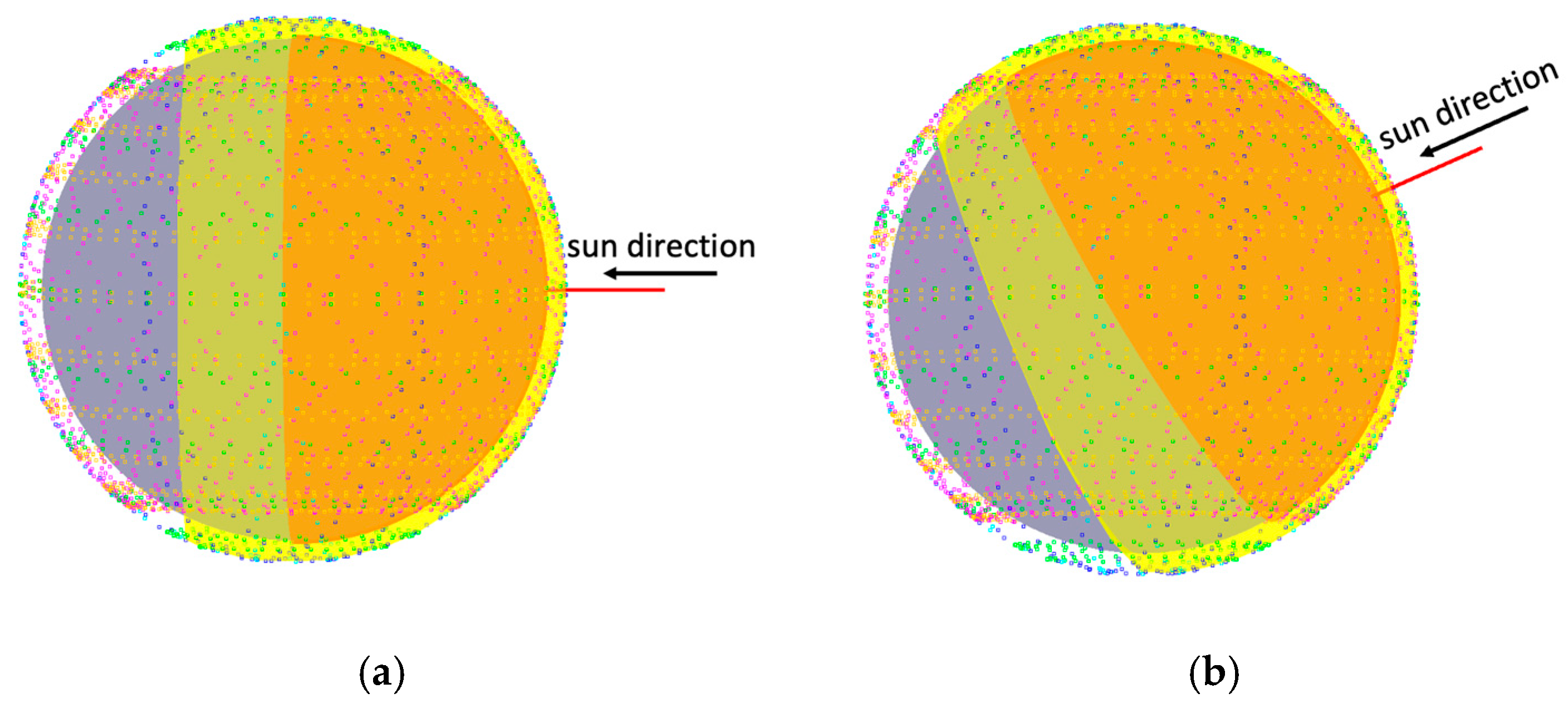
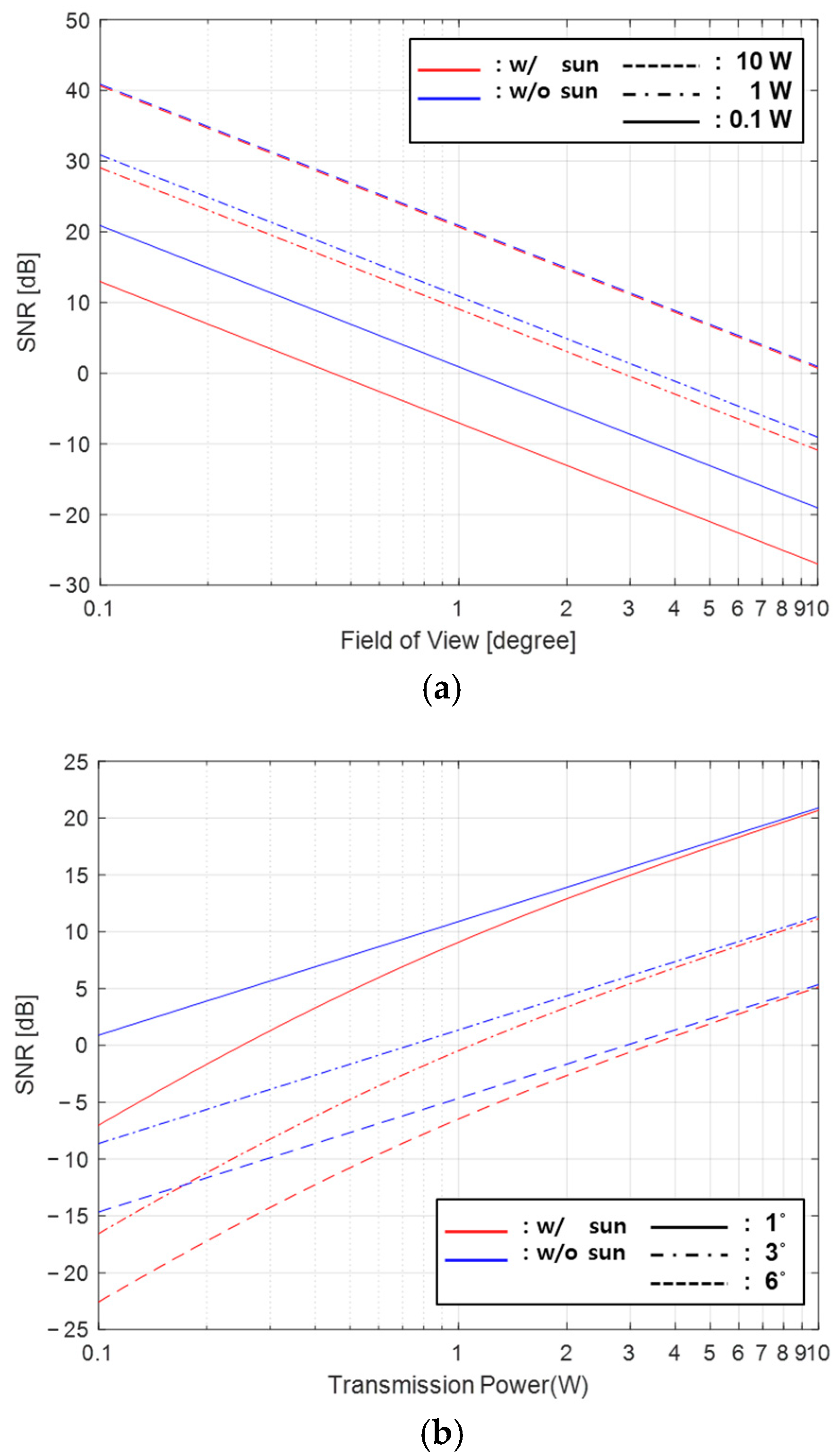
3.1. Solar Irradiation Simulation Results

This section presents the results of the simulations that evaluate the impact of sunlight interference on the communication performance by examining the transmission power and FoV, based on the definitions provided in Section 2.1.
In the first simulation, the SNR is assessed at various transmission powers of 0.1 W, 1 W, and 10 W, with FoVs ranging from 0.1° to 10°. The results, depicted in Figure 8a, overall, suggest that a higher transmission power allows for a wider FoV operation with minimal performance degradation and vice versa. As the transmission power decreases, the SNR gap between the ideal case and the case affected by solar interference becomes wider. This gap becomes wider as the FoV widens, reaching up to 10 dB at 0.1 W for the widest FoV. For the highest transmission power of 10 W, the SNR remains close to the ideal value, regardless of the solar irradiance and FoV, demonstrating strong resistance to interference. At significantly narrow FoVs of between 0.1° and 0.2°, the gap becomes trivial across all the power levels, meaning that the effects of the solar interference are negligible in these cases. Notably, the required FoV for maintaining a suitable SNR becomes narrower as the transmission power decreases, implying that weaker signals need a narrower FoV to mitigate interference and maintain performance. This is because a reduction in the optical signal power increases susceptibility to ambient noise, such as solar irradiance.
The second simulation, as shown in Figure 8b, focuses on the influence of the FoV on the communication performance under varying transmission power conditions. The analysis is conducted at FoVs of 1° and 3°, with the addition of a 6° FoV, corresponding to the practical application of a fast-steering mirror (FSM) module in positioning acquisition and tracking (PAT) systems [18]. The results demonstrate that the transmission power is directly proportional to the SNR and that a higher power level is required to maintain performance as the FoV widens. For instance, at a 1° FoV, the required transmission powers to achieve an SNR of ~10 dB are 0.78 W without sunlight interference and 1.14 W with sunlight interference. At a 3° FoV, these values increase to 7.03 W and 7.47 W, respectively. When using a 6° FoV, the FSM configuration fails to reach the SNR threshold, even at a high transmission power of 10 W.
As a result, the transmission power should be increased as the FoV widens. For example, at the same power level (1 W) with sunlight interference, the SNR significantly decreases by 15.6 dB when increasing the FoV from 1° to a 6° FoV. This indicates that a wider FoV, although enabling the detection of optical signals over a wider angular range, also allows for more interference, such as solar irradiance. Consequently, as the transmission power increases, the SNR gap between the ideal and illuminated signals narrows, confirming the importance of balancing power and the FoV to mitigate solar interference effectively.

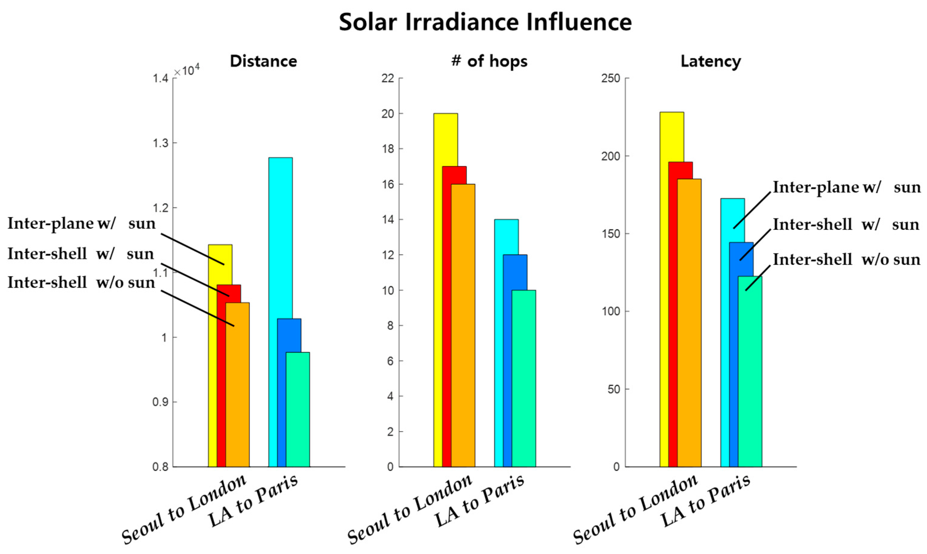
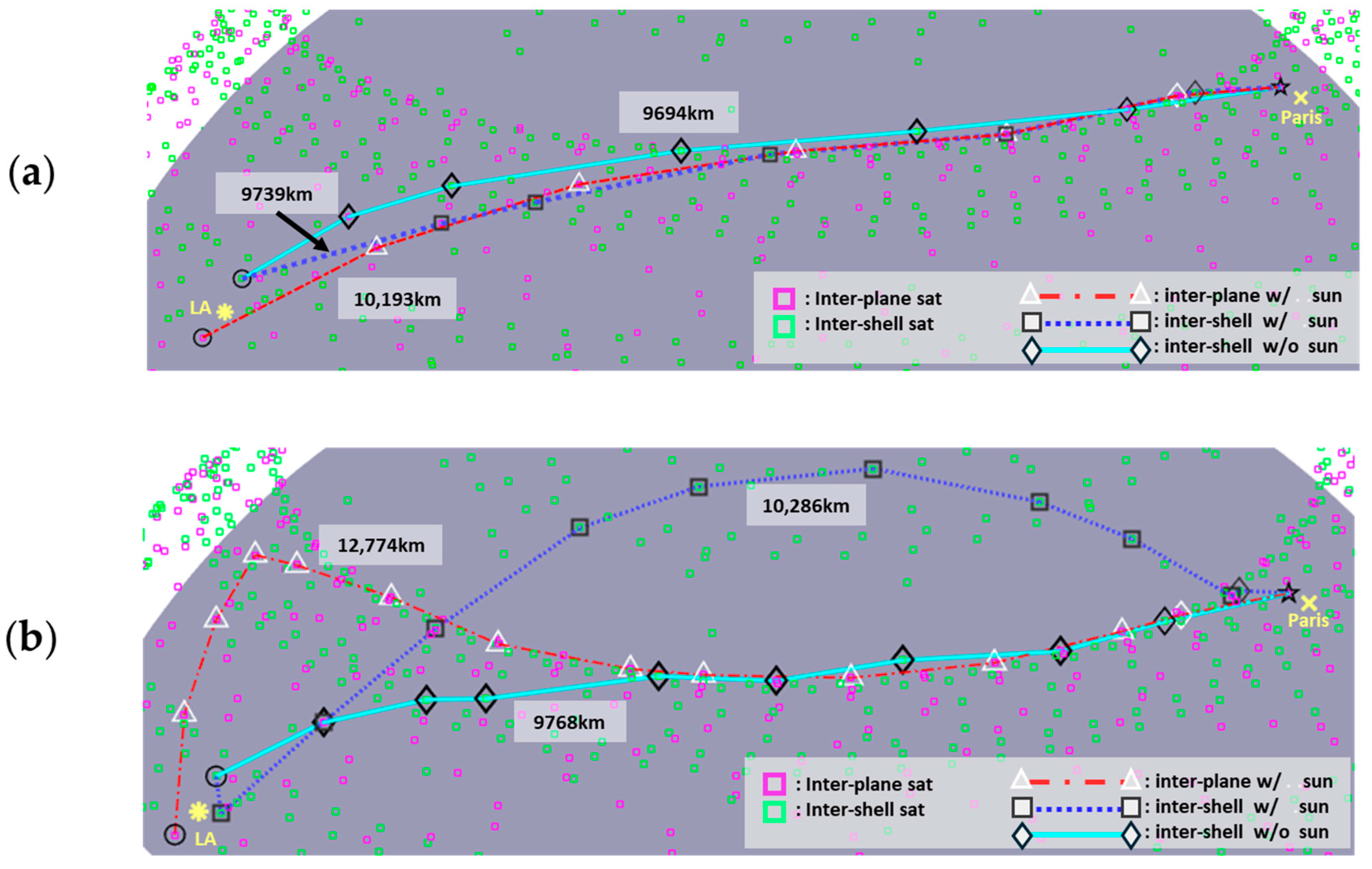
3.2. Path Optimization Strategies via Inter-Plane and Inter-Shell Configurations

Figure 9 and Figure 10 and Table 4 present the simulation results to compare the effectiveness of the path optimization in inter-plane and inter-shell configurations in avoiding solar irradiance. The scenarios involve two intercontinental routes: “Seoul–London” and “LA–Paris.” To show diverse seasonal situations and evident cases, the “Seoul–London” scenario under spring or fall conditions (0° axial inclination) and the “LA–Paris” scenario under summer conditions (23.5° axial inclination) are chosen. The shortest solar-interference-free optical link is found with four optical transceiver modules positioned in the four cardinal directions: east, west, south, and north.
The simulation results in Figure 9 show that the impact of the solar irradiance on the communication performance can be significant, compared to the case without solar irradiance, in three comparison categories: (i) the overall path distance, (ii) the number of hops, and (iii) the latency. The results also suggest that in terms of avoiding the solar irradiance, the inter-shell configuration outperforms the inter-plane one in all three categories. Notably, compared to the inter-plane one, the inter-shell approach reduces the overall path distance by 600 km in the “Seoul–London” scenario and 2500 km in the “LA–Paris” scenario.
Table 4 provides a detailed breakdown of the link configurations for the “Seoul–London” scenario. The results indicate that extending the transmission distance allows for more links to be generated, leading to a higher total number of available links compared to those available in scenarios with shorter distance constraints. In addition, inter-shell configurations consistently outperform inter-plane configurations. As shown in Table 4a,b, inter-shell setups have a greater number of links than inter-plane setups. This abundance of alternative links enables inter-shell configurations to circumvent solar interference more effectively, even though the disconnection rate is higher. The inclination of the rotational axis also significantly affects link configurations, particularly in inter-plane setups. During summer, when the solar angle reaches 23.5°, the disconnection rate is nearly twice as high as those in spring or fall. Furthermore, inter-shell configurations, with orbital inclinations distributed widely between 50° and 100°, are more susceptible to solar interference during summer. This is mainly because of the sun’s incident angle being more aligned to the satellites’ orbital angles.
Figure 10 visualizes the path configurations in the “LA–Paris” scenario for inter-shell and inter-plane configurations. In all the cases, the paths simulated in spring (Figure 10a) are shorter than those simulated in summer (Figure 10b). These simulation outcomes align with the comparisons shown in Figure 9, confirming that inter-shell configurations are more robust than inter-plane configurations against solar interference and capable of providing a short path length, a low number of hops, and low latency.

4. Discussion and Conclusions

This research has investigated the impact of solar irradiation interference on optical inter-satellite links, focusing on the signal-to-noise ratio and path configuration simulations. The ideal case and solar-irradiance-affected cases for different field-of-view angles and transmission powers have been simulated. When the FoV is reduced to 1° or less, the signal-to-noise ratio is maintained despite interference from solar irradiance, with transmission powers close to 1 W. However, for an FoV of 6°, more transmission power (>10 W) is required to overcome solar irradiance.
Using a multi-directional FoV model and Heron’s-law-based categorization, the impacts of solar irradiance on inter-plane and inter-shell configurations have been investigated. The detour strategy, in two inter-continental scenarios, suggests that the inter-shell configuration outperforms the inter-plane one, reducing the overall path distance by up to 2500 km. Notably, because of the orbital inclination, inter-shell configurations exhibited higher link loss during summer in the northern hemisphere than inter-plane configurations; however, by offering more than five times the number of alternative paths, better performance is provided under solar irradiance.
Although satellite laser communication terminals with high optical powers could mitigate the impact of solar irradiation, it is a challenging solution in space-based links, mainly because of high energy consumption, thermal management challenges, weights and costs, and a reduction in the satellite’s lifespan. Consequently, future research should focus on developing models that minimize solar interference using lower transmission power, with the development of next-generation laser communication terminals, by applying an advanced machine-learning approach and energy-efficient and compact schemes, such as integrated sensing and communications (ISACs). Future work could explore the alteration vulnerability from the satellite attitude destabilization on the influence of solar irradiation through dynamic link modeling, providing deeper insights into the system’s robustness.

Author Contributions

Conceptualization, J.S.H. and H.C.; methodology, J.S.H.; software, J.S.H.; validation, J.S.H., J.-Y.L. and H.C.; formal analysis, J.S.H. and J.-Y.L.; investigation, J.S.H.; resources, H.C.; data curation, J.S.H. and J.-Y.L.; writing—original draft preparation, J.S.H.; writing—review and editing, J.-Y.L.; visualization, J.S.H. and J.-Y.L.; supervision, H.C.; project administration, H.C.; funding acquisition, H.C. All authors have read and agreed to the published version of the manuscript.

Funding

This research was supported by MSIT (the Ministry of Science and ICT), Korea, under the ITRC (Information Technology Research Center) support program (IITP-2025-RS-2023-00259061) supervised by IITP (the Institute for Information and Communications Technology Planning and Evaluation). Also, this research was supported by a National Research Foundation of Korea (NRF) grant funded by MSIT (RS-2023-00253346).

Institutional Review Board Statement

Not applicable.

Informed Consent Statement

Not applicable.

Data Availability Statement

The datasets presented in this article are not readily available. Requests to access the datasets should be directed to the corresponding author.

Conflicts of Interest

The authors declare no conflicts of interest.

References

  1. Xiao, Z.; Fan, P.; Gao, Y.; You, X.; Dai, L. LEO Satellite Access Network (LEO-SAN) Toward 6G: Challenges and Approaches. IEEE Wirel. Commun. 2024, 31, 89–96. [Google Scholar] [CrossRef]
  2. Bhattacharjee, D.; Bhandari, N.; Tiwari, A.; Singh, K.; Sridhar, S.; Ravichandran, R.; Panda, G. On-Demand Routing in LEO Mega-Constellations With Dynamic Laser Inter-Satellite Links. IEEE Trans. Aerosp. Electron. Syst. 2024, 60, 7089–7105. [Google Scholar] [CrossRef]
  3. Lin, X.; Cioni, S.; Charbit, G.; Chuberre, N.; Hellsten, S.; Boutillon, J.-F. On the Path to 6G: Embracing the Next Wave of Low Earth Orbit Satellite Access. IEEE Commun. Mag. 2021, 59, 36–42. [Google Scholar] [CrossRef]
  4. Kurnaz, S.; Abdulwahid, M.M. The Channel WDM System Incorporates Optical Wireless Communication (OWC) Hybrid MDM-PDM for Higher Capacity (LEO-GEO) Inter-Satellite Link. Optik 2022, 273, 170449. [Google Scholar] [CrossRef]
  5. Singh, K.; Chebaane, S.; Ben Khalifa, S.; Benabdallah, F.; Ren, X.; Khemakhem, H.; Grover, A.; Singh, M. Investigations on Mode-Division Multiplexed Free-Space Optical Transmission for Inter-Satellite Communication Link. Wirel. Netw. 2022, 28, 1003–1016. [Google Scholar] [CrossRef]
  6. Kurnaz, S.; Turkben, A.; Hayal, M.R.; Elsayed, E.; Juraev, D. Inter-Satellite Optical Wireless Communication (Is-OWC) Trends: A Review, Challenges, and Opportunities. IOP Conf. Ser. Mater. Sci. Eng. 2024, 3, 1–15. [Google Scholar]
  7. Chaudhry, A.U.; Yanikomeroglu, H. Laser Intersatellite Links in a Starlink Constellation: A Classification and Analysis. IEEE Veh. Technol. Mag. 2021, 16, 48–56. [Google Scholar] [CrossRef]
  8. Hwang, J.S.; Lee, J.-Y.; Chun, H. Ego-Satellite Perspective Multi-PAT Configurations for Optical Inter-Satellite Links. IEEE Access 2024, 12, 144412–144419. [Google Scholar] [CrossRef]
  9. Excelitas Technologies. C30733EH-1 InGaAs Datasheet. Available online: https://www.excelitas.com/file-download/download/public/104302?filename=C30733EH-1_InGaAs_APD_Datasheet.pdf (accessed on 19 January 2025).
  10. Thorlabs. DFB15TK-Turkey Low-Noise DFB System. Available online: https://www.thorlabs.com/thorproduct.cfm?partnumber=DFB15TK (accessed on 19 January 2025).
  11. Islim, M.S.; Videv, S.; Haas, H. The Impact of Solar Irradiance on Visible Light Communications. J. Lightwave Technol. 2018, 36, 2376–2386. [Google Scholar] [CrossRef]
  12. Yong, J.; Wen, F.; Hu, Z.; Fan, F.; Qiu, K. High-Dynamic Transmission Modeling for Laser Inter-Satellite Links (LISLs). In Proceedings of the 2022 Asia Communications and Photonics Conference (ACP), Shenzhen, China, 5–8 November 2022; pp. 590–594. [Google Scholar] [CrossRef]
  13. Cornwell, D. Space-Based Laser Communications Break Threshold. Opt. Photonics News 2016, 27, 24–31. [Google Scholar] [CrossRef]
  14. NASA. Laser Communications Relay Demonstration (LCRD) Overview. Available online: https://www.nasa.gov/mission_pages/tdm/lcrd/index.html (accessed on 19 January 2025).
  15. TELESAT. Telesat Lightspeed LEO Network. Available online: https://www.telesat.com/leo-satellites/ (accessed on 19 January 2025).
  16. Jin, J.; Shang, L.; Yang, Z.; Wang, H.; Li, G. A Local Pre-Rerouting Algorithm to Combat Sun Outage for Inter-Satellite Links in Low Earth Orbit Satellite Networks. Appl. Sci. 2024, 14, 1625. [Google Scholar] [CrossRef]
  17. Pachler, N.; del Portillo, I.; Crawley, E.F.; Cameron, B.G. An Updated Comparison of Four Low Earth Orbit Satellite Constellation Systems to Provide Global Broadband. In Proceedings of the 2021 IEEE International Conference on Communications Workshops (ICC Workshops), Montreal, QC, Canada, 14–23 June 2021; pp. 1–7. [Google Scholar] [CrossRef]
  18. Thorlabs. FSM75-P01 Fast Steering Mirror (SpecSheet). Available online: https://www.thorlabs.de/thorproduct.cfm?partnumber=FSM75-P01 (accessed on 19 January 2025).
Figure 1. Definition of the maximum illumination distance using the triangle from Heron’s law.
Applsci 15 03364 g001
Figure 2. Difference between the area of the daytime and that of illuminated satellites by season: spring (a) and summer (b). The orange-colored area (inside): noon on the earth ground and the yellow-colored area (outside): maximum reachable area of solar irradiation to LEO satellites.
Applsci 15 03364 g002
Figure 3. Impact of solar irradiance on multi-directional receivers in a satellite with an incident angle of solar irradiance on the satellite θ s with 0° in (a), 45° in (b), and 135° in (c).
Applsci 15 03364 g003
Figure 4. Illustrations showing (a) the solar-irradiance-influenced case and (b) the non-influenced case, despite the entities being at the exact same locations.
Applsci 15 03364 g004
Figure 5. Differences in satellite classification based on seasons (within the northern hemisphere).
Applsci 15 03364 g005
Figure 6. Multi-directional transceiver model based on satellite-centric coordinates, including the solar irradiance as (a) non-blinded and within FoV, (b) non-blinded but outside FoV, and (c) within FoV but blinded.
Applsci 15 03364 g006
Figure 7. The cross-sectional view of the inter-shell configuration: orange (540 km, the lowest layer), magenta (550 km, second layer), cyan and blue (560 km, third layer highlighted to represent the same altitude), and green (570 km, the highest layer).
Applsci 15 03364 g007
Figure 8. SNR graphs for the ideal case and the illuminated case for solar irradiance interference (a) across three transmission power levels (0.1 W, 1 W, and 10 W) and (b) across three FoV resolutions (1°, 3°, and 6°).
Applsci 15 03364 g008
Figure 9. Bar graphs to compare the O-ISL performances under solar irradiance in the inter-plane and inter-shell configurations in intercontinental scenarios, such as ‘Seoul–London’ and ‘LA–Paris’.
Applsci 15 03364 g009
Figure 10. Visualized simulation results for O-ISL path configurations in (a) spring and (b) summer.
Applsci 15 03364 g010
Table 1. Investigation coverage comparison.
FeatureRef. [12]Ref. [16]Our Work
Dedicated solar irradiance modelingOOO
Distinguishment of unaffected solar exposureΔXO
Analysis of seasonal influenceXXO
Fully adaptive
multi-directional FoV
XΔO
Robustness against varying orbital inclinationsΔΔO
Large-scale multi-shell
scenarios
XXO
“O” = fully supported, “Δ” = partial/limited, and “X” = not covered.
Table 2. Simulation parameters.
NotationDefinitionValue(s)
r s Altitude of the satellite540 km, 550 km,
560 km, and 570 km
r E Radius of the Earth6371 km
d s u n Distance between Earth
and the sun
1 AU
(149,597,870 km)
A d APD’s area 707   μ m 2
θ F o V Angle of the field of view1°, 3°, and 6°
P M a x L The maximum transmission power0.1 W, 1 W, and 10 W
MBeam divergence used for m65 μrad
F Excess noise factor5.5
B APD’s bandwidth3 GHz
R L Load’s resistance50 Ω
Table 3. Orbital components in the inter-shell.
Number of PlanesNumber of Satellites
Per Plane
Altitude (km)Inclination
722254053.2°
722255053°
65856097.6°
44356097.6°
362057070°
Table 4. Link configuration information obtained under various conditions from ‘Seoul to London’. Part (a) represents the inter-plane, and (b) represents the inter-shell configurations.
σ Link ConstraintLink LossDistribution
(a) Inter-plane
0 ° 1000 km5.54%7232/7656
3000 km6.57%50,236/53,768
23.5 ° 1000 km11.60%6768/7656
3000 km11.59%47,538/53,768
(b) Inter-shell
0 ° 1000 km10.82%34,580/38,776
3000 km8.85%293,780/322,292
23.5 ° 1000 km12.47%33,942/38,776
3000 km12.14%283,154/322,292
Disclaimer/Publisher’s Note: The statements, opinions and data contained in all publications are solely those of the individual author(s) and contributor(s) and not of MDPI and/or the editor(s). MDPI and/or the editor(s) disclaim responsibility for any injury to people or property resulting from any ideas, methods, instructions or products referred to in the content.

