Article

The Design, Analysis, and Verification of an Axial Flux Permanent Magnet Motor with High Torque Density

1
College of Mechanical & Electrical Engineering, Nanjing University of Aeronautics and Astronautics, Nanjing 210016, China
2
Beijing System Design Institute of Electro-Mechanic Engineering, Beijing 100081, China
3
School of Mechatronics Engineering, Harbin Institute of Technology, Harbin 150001, China
4
School of Engineering, Beijing Institute of Petrochemical Technology, Beijing 102617, China
*
Author to whom correspondence should be addressed.
Appl. Sci. 2025, 15(6), 3327; https://doi.org/10.3390/app15063327
Submission received: 11 February 2025 / Revised: 4 March 2025 / Accepted: 7 March 2025 / Published: 18 March 2025

Abstract

:
Aiming at the defects of long axial size and low torque density of the existing radial flux permanent magnet motor, this paper proposes an axial flux permanent magnet synchronous motor (AFPMM) with a double-stator and single-rotor structure based on the design requirements of the motor for mechanical dogs’ electric drive joints. The finite element method is employed to evaluate the static magnetic field, load characteristics, and associated losses. The analysis indicates that the average magnetic flux density in the air gap reaches approximately 0.95 T, with a rated torque of around 2.72 N.m, a peak torque of 7.6 N.m, and an efficiency of approximately 87.73%. The electromagnetic torque model is developed using the Maxwell tensor method, allowing for the effects of critical structural parameters on torque to be investigated. By optimizing the design for torque density, an improvement of nearly 20% is achieved. A prototype was fabricated and tested, demonstrating good agreement between simulation and experimental results. This research introduces a novel approach for designing axial flux motors with high torque and power densities.

1. Introduction

The axial flux permanent magnet motor (AFPMM) features a compact motor structure that differentiates it from conventional designs. In both industrial and everyday applications, motors serve as essential energy conversion devices, transforming electrical energy into mechanical energy and driving various types of equipment. With the rapid growth of modern industrial production, the demand for motors with higher performance is steadily increasing. Permanent magnet synchronous motors (PMSMs), known for their excellent dynamic response and high power density, have attracted significant attention in various fields both domestically and internationally [1]. Mechanical dogs, as an advanced robotic technology, require efficient, compact, and responsive power sources to support their complex movements and tasks. Axial flux motors have become an ideal power choice for mechanical dogs, enhancing their performance and making them more agile and efficient when executing tasks. To meet the stringent performance requirements of specialized applications, such as in aircraft, motors with optimized structures and superior performance are essential [2]. Among commercially available motors, radial flux motors are the most common. However, the axial flux motor introduced in this paper is designed to be compact, flat, and highly efficient in heat dissipation [3,4]. These characteristics make it particularly suitable for use in transportation [5,6,7], wind energy [8,9,10], and aviation. In the field of unmanned aerial vehicles, where installation space for motors is limited, the axial flux motor offers an effective solution. Additionally, its relatively simple control system reduces the complexity of development, enhancing its application potential. Permanent magnet motors, characterized by their high power density and efficiency, have become ideal actuators for applications such as electric vertical take-off and landing vehicles.
In 1991, Japanese researchers applied the AFPMM to the wheel hubs of new energy vehicles to drive the car, creating a prototype vehicle capable of reaching a top speed of 311 km/h. In 1992, Chalmers B. J. and Spooner E. developed a ring-wound motor, realizing the application of an AFPMM in wind power generation [11]. In 1998, researchers such as Zhang Yuejin from Shanghai University simulated the magnetic field of a dual-stator axial flux permanent magnet generator using a three-dimensional scalar finite element method and conducted a preliminary design and analysis of the motor. In 2002, American researchers Jacek F. Gieras and Izabella A. Gieras developed a novel AFPMM with dual-side rotors, achieving relatively high air gap flux density [12]. In 2006, Shao Li and Fan Yu from Beijing Jiaotong University, based on Maxwell’s electromagnetic equations, used the method of separation of variables to analyze the distribution of the air gap magnetic field in axial flux permanent magnet brushless DC motors. In 2008, Mwwrten J. Kamper, Rong Jie Wang, and other researchers analyzed the impact of variations in winding configurations on the performance of axial flux coreless motors [13]. In 2009, Sang Jianbin and Li Wan, based on the structure and operating principles of the flux-switching axial flux permanent magnet wind generator, developed a three-phase, 12/10-pole flux-switching axial flux permanent magnet wind generator, which was applied in a direct-drive variable-speed constant-frequency wind power generation system. In 2010, Lin Mingyao and Zhang Lei analyzed the positioning torque of Axial Flux Flux-Switching Permanent Magnet (AFFSPM) motors rapidly by combining analytical and finite element methods, achieving an efficient reduction of the detent torque in these motors. In 2013, D. Ahmed and A. Ahmad from Pakistan applied numerical and analytical algorithms to axial motor research for the first time. Their work involved modeling an axial flux coreless generator for a direct-drive low-speed wind turbine, along with dynamic system simulations [14]. In 2021, Andrea Credo, Marco Tursini, and other researchers conducted a 3D multiphysics analysis of the axial flux permanent magnet motor in electric vehicles, investigating the motor’s performance, thermal behavior, and electromagnetic forces [15]. The optimization of AFPMM performance has been a significant area of focus in recent years. In 2013, Pop A. A. and Radulescu combined finite element and analytical methods for the simulation modeling and calculation of AFPMMs and applied sequential quadratic programming optimization algorithms to optimize the shape and size parameters of the AFPMM rotor magnets, effectively reducing harmonic content in the air gap magnetic flux density [16]. In 2014, H. Tiegna, Y. Amara, and G. Barakat developed a fast 3D electromagnetic simulation method to address the time constraints of 3D modeling while simultaneously studying methods to minimize cogging torque in axial motors [17]. In 2015, Pia Lindh, Chris Gerada, and other researchers studied the temperature rise issues of axial flux motors and analyzed the effects of liquid cooling systems on thermal distribution using computational fluid dynamics. Their study employed a 100 kW single-rotor, double-stator axial flux generator as an example [18]. In 2016, Yee Pien Yang and Guan Yu Shih proposed an optimization design method for the axial flux permanent magnet motor in electric vehicles based on driving scenarios. The goal was to reduce energy consumption by minimizing the motor’s weight and the frequency of operation points during driving cycles [19]. In 2017, Reza Mirzahosseini and Ahmad Darabi proposed an optimized design algorithm for a surface-mounted-magnet dual-sided toroidal-slotless axial flux permanent-magnet motor. Using a particle swarm optimization algorithm, they achieved maximum machine efficiency and power density, demonstrating the feasibility of the design through MATLAB simulations [20]. In 2018, Jianfei Zhao, Minqi Hua, and Tingzhang Liu introduced a sliding mode vector control system for the axial flux permanent magnet synchronous motor (AFPMSM) in electric vehicles. By optimizing control strategies in conjunction with fuzzy control, they improved torque ripple, thus enhancing the high-efficiency range and driving range of electric vehicles [21]. In 2020, Filip Kutt and Krzysztof Blecharz introduced the counter-rotating concept—commonly used in ships and helicopters—into AFPMM design and manufacturing, targeting applications in wind power systems [22,23]. In 2024, Wei Ge, Yiming Xiao, and other researchers employed Differential Evolution and Cuckoo Search algorithms to optimize and compare the torque performance of the axial flux permanent magnet motor. Their approach effectively reduced cogging torque, increased average output torque, and reduced torque ripple [24].
In response to the design requirements for motors used in electric drive joints of mechanical dogs, this paper proposes a high-torque-density, high-power-density axial flux permanent magnet motor electromagnetic scheme to enhance the torque density. A three-dimensional finite element model was developed using Maxwell software to perform electromagnetic simulations under static and transient conditions. Additionally, losses in various electromagnetic components were analyzed. The Maxwell tensor method was employed to establish an electromagnetic torque model, identify the effects of key structural parameters on torque, and optimize the motor’s design for torque density. Finally, a prototype was fabricated, and its performance was validated through torque testing. It is hoped that the AFPMM scheme will provide certain reference value for the design of motors used in electric drive joints of mechanical dogs, enhancing their performance and efficiency in executing complex tasks and movements.

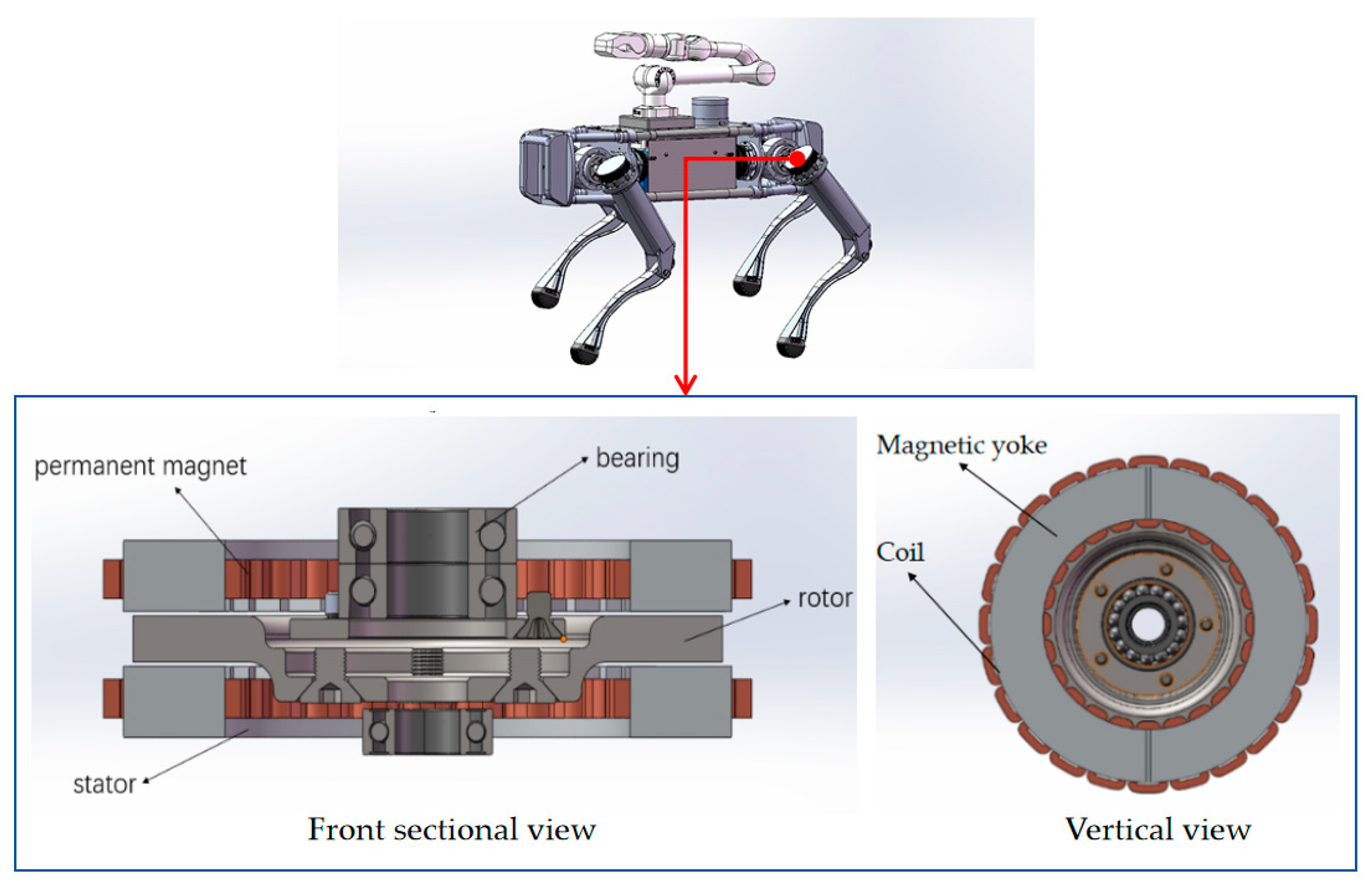
2. Structure and Working Principle

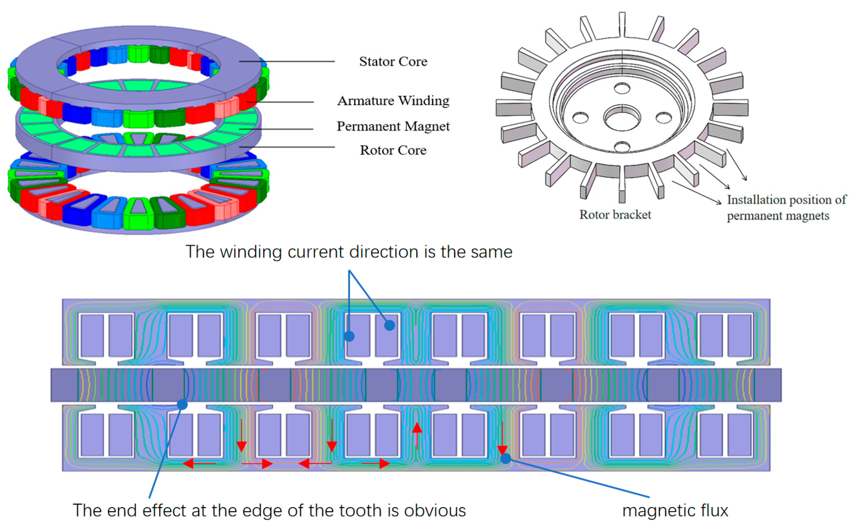
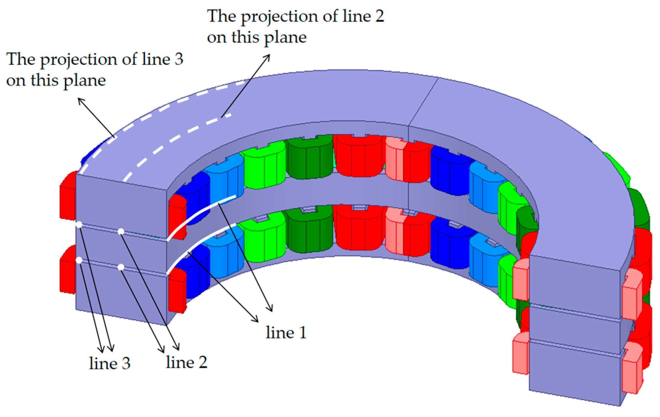
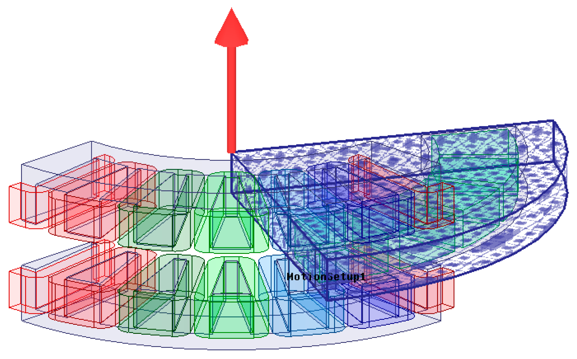
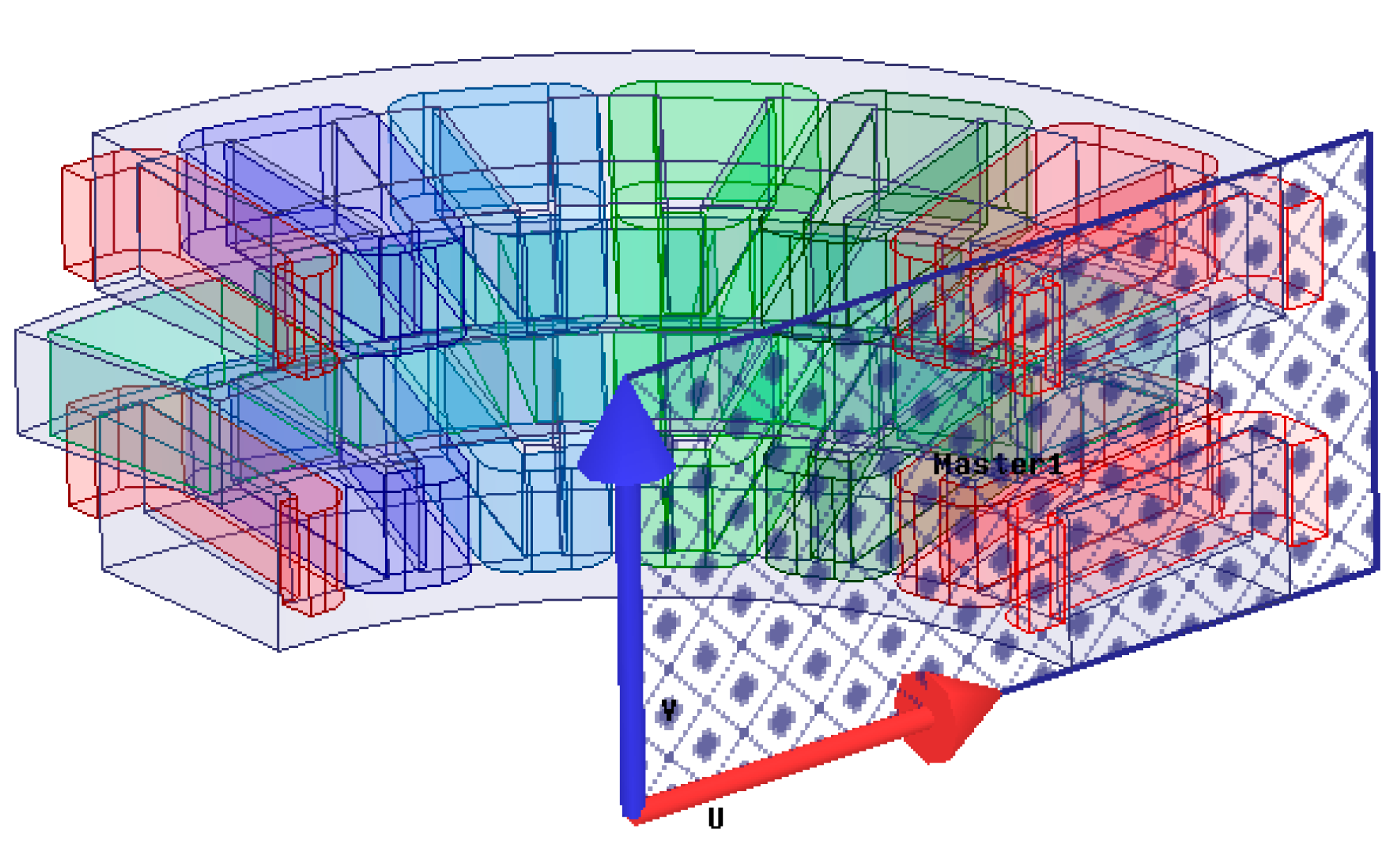
2.1. Structure and Composition of Axial Flux Permanent Magnet Synchronous Motor

The axial flux permanent magnet motor designed in this paper was a three-phase motor, with each phase having 10 turns connected in series. The motor was designed with 10 poles and a rated speed of 1080 rpm, corresponding to a frequency of 180 Hz. The double-sided internal rotor structure (AFIR) consisted of two stators and one intermediate rotor, forming a symmetrical double air gap configuration. As shown in Figure 1, the stator included a core and windings. The core, made of silicon steel sheets, provided the magnetic circuit, while the windings, made of copper or aluminum wire, generated the magnetic field. The stator teeth and slots adopted a fractional-slot structure with a pole-slot combination of 20 poles and 24 slots. The stator slot depth was 5.2 mm, and the slot opening width was 4.8 mm. The windings were implemented using a multi-strand parallel winding scheme, with 6 strands in parallel per slot. The rotor consisted of a core and permanent magnets, where the core was also made of silicon steel sheets to form the magnetic circuit, and the permanent magnets, made of materials such as neodymium-iron-boron, generated the magnetic field. The intermediate rotor was subjected to axial magnetic forces from both the upper and lower stators, which counteracted each other, thereby reducing the bearing load and mechanical losses. This contributed to an increase in the motor’s power density and efficiency. The windings were placed on both stators, while the permanent magnets were mounted on the intermediate rotor. The magnets on the rotor can be arranged in two configurations: surface-mounted or embedded. In the surface-mounted configuration, the magnetic flux passes through the rotor bracket, requiring the use of magnetically conductive materials. To prevent the rotor bracket’s magnetic circuit from becoming saturated, the axial size of the bracket must be increased. This can increase the length of the magnetic path and reduce the magnetic reluctance of the path, thereby enhancing the magnetic conductivity and avoiding saturation of the magnetic circuit. This approach is not conducive to the flat design of the electric drive joint. In this paper, an embedded structure was adopted, where the magnetic flux path passed only through the permanent magnets. The rotor bracket can be made of non-magnetic materials, which helps to reduce the overall weight, shorten the axial dimension of the motor, and further enhance the torque density of the motor.

2.2. Working Principle

The axial flux motor (AFM) features a unique structure that operates based on the principle of electromagnetic induction. As shown in Figure 2, the motor’s magnetic flux predominantly flows along the axial direction. The magnetic field produced by the stator interacts with the magnetic field of the rotor’s permanent magnets, forming a closed magnetic flux circuit. When the stator windings are energized, they produce a magnetic field that interacts with the field generated by the rotor’s permanent magnets, creating torque to drive the motor. The permanent magnets generate a stable magnetic field, which interacts with the stator’s magnetic field to produce an electromagnetic force, ultimately driving the rotor. This interaction between the magnetic fields of the stator and the rotor allows for the rotor to convert electromagnetic energy into mechanical energy, which is output by the motor.

3. Electromagnetic Characteristic Analysis

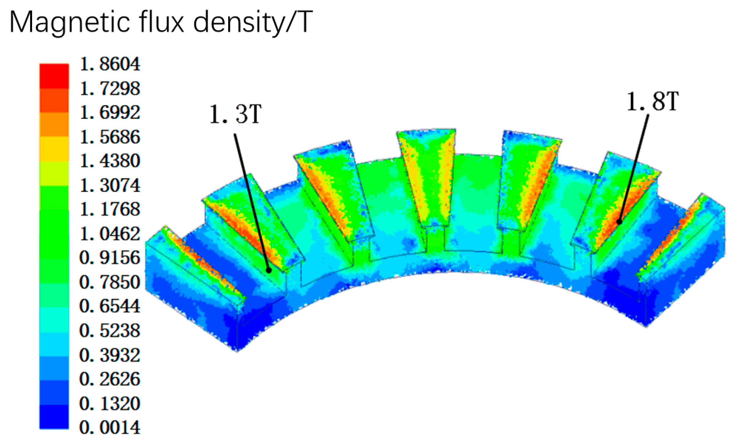
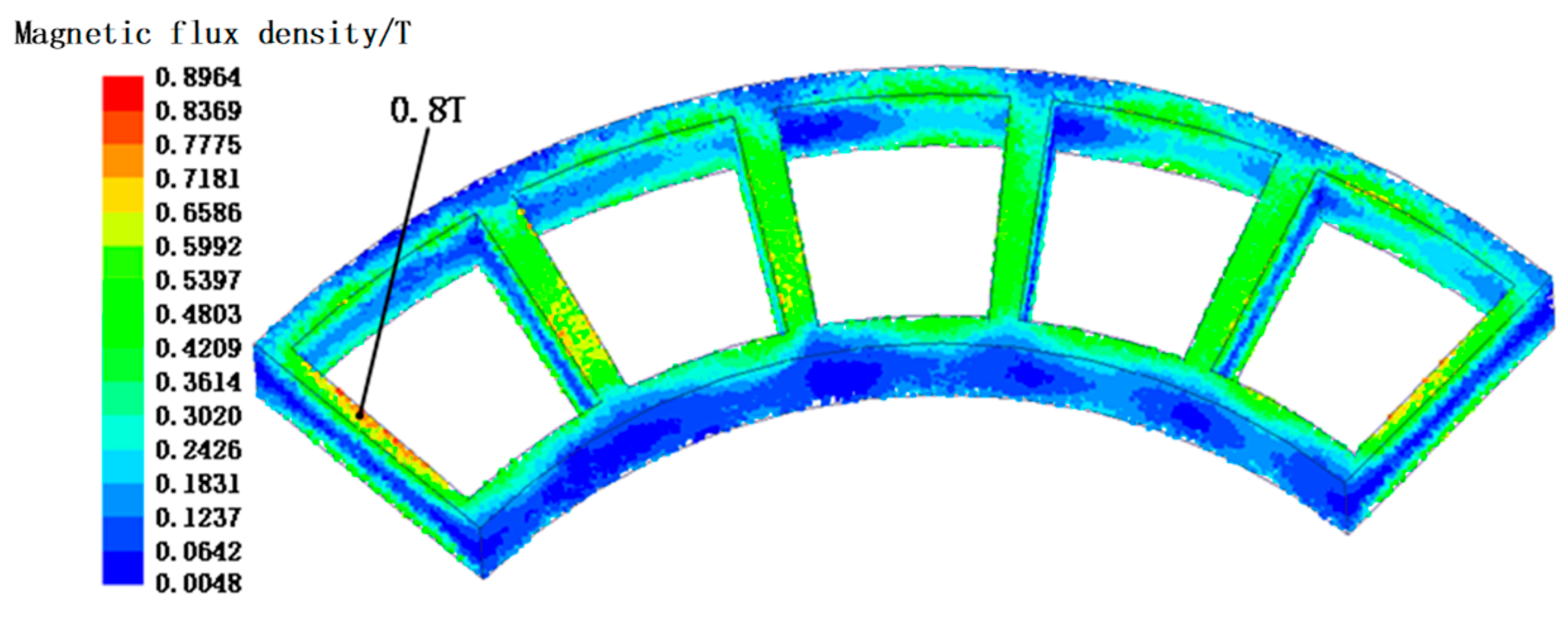
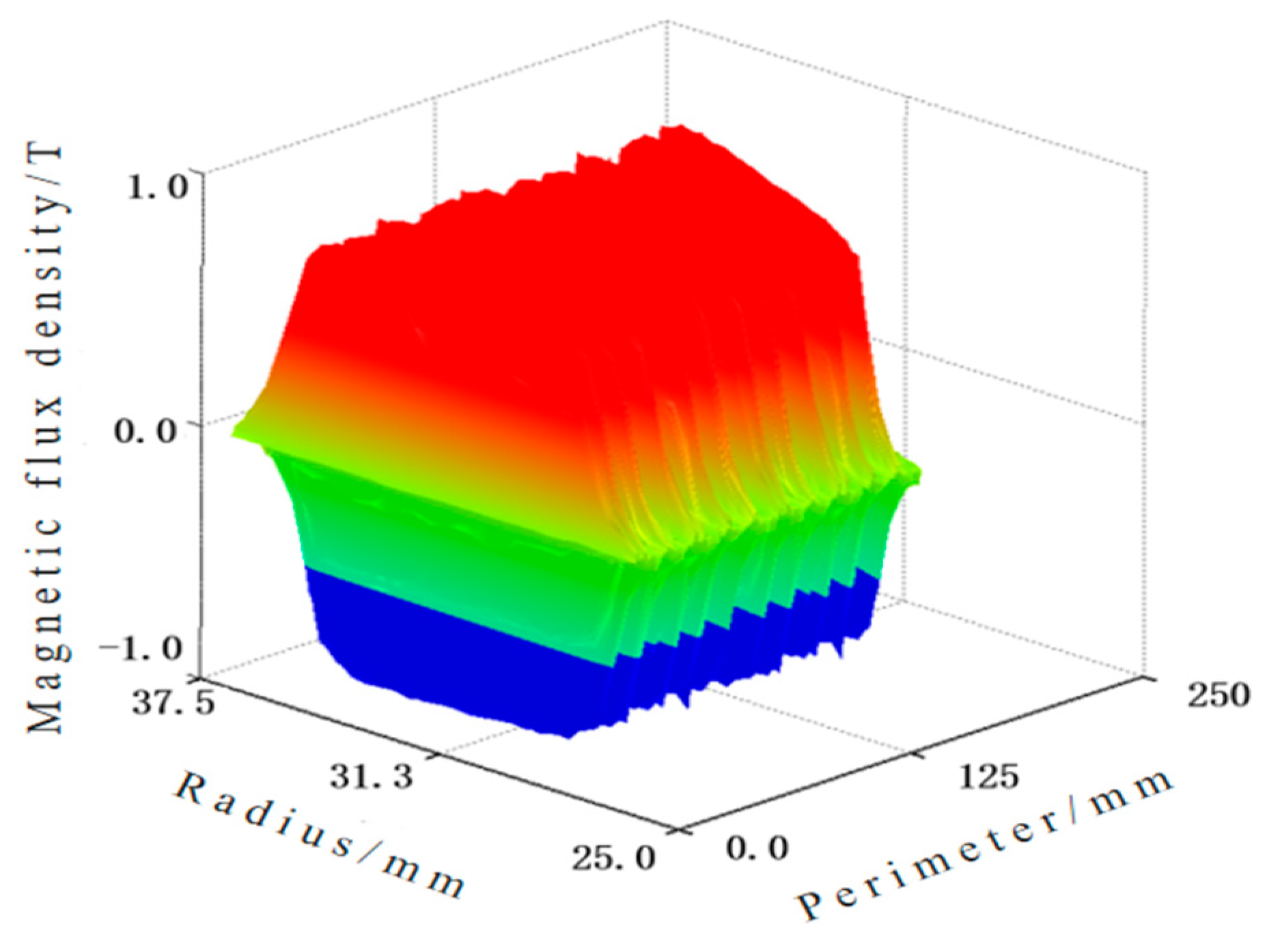
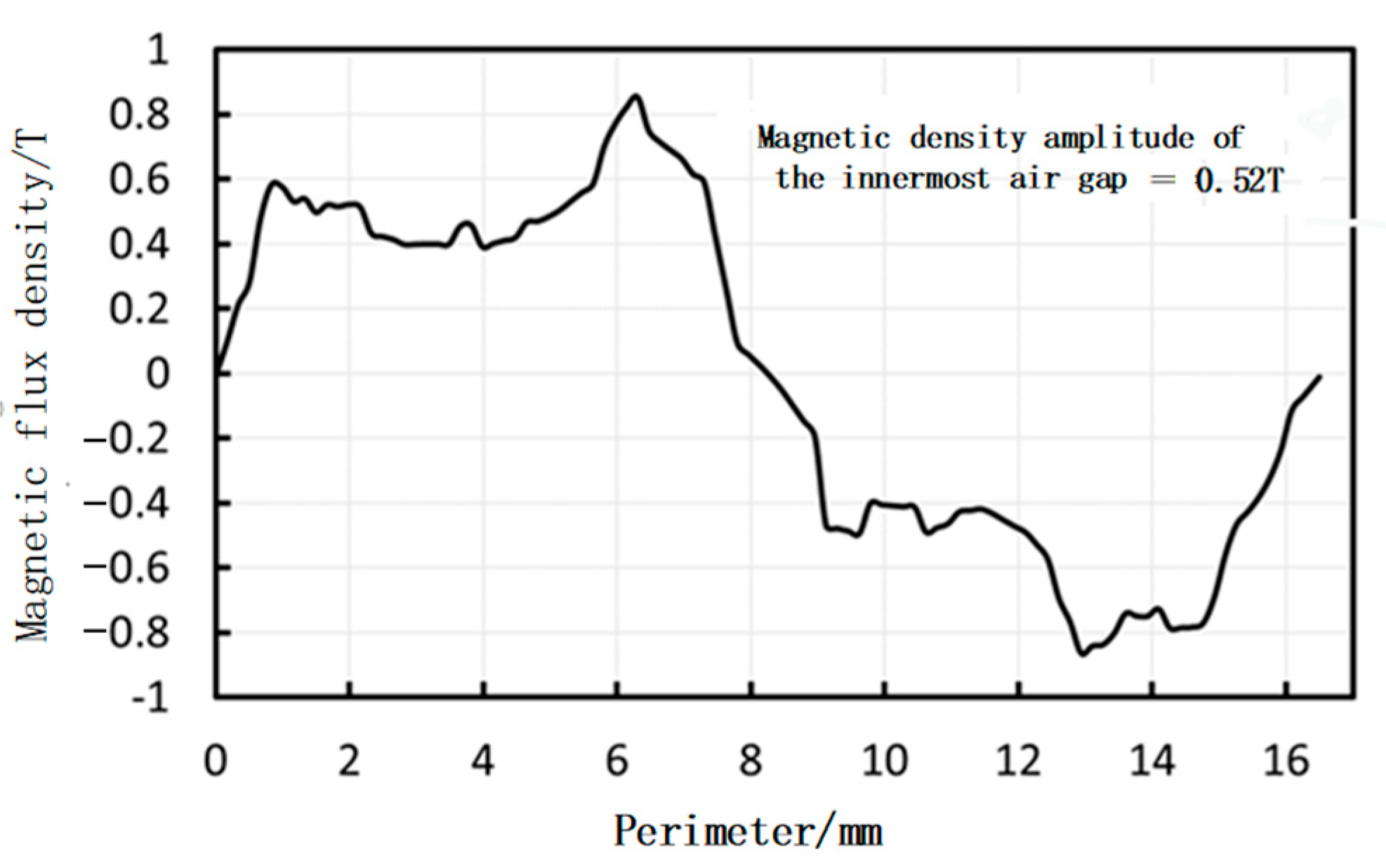
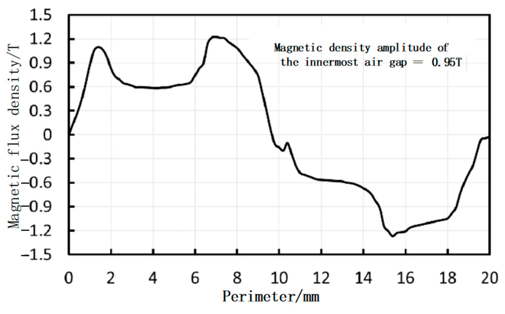
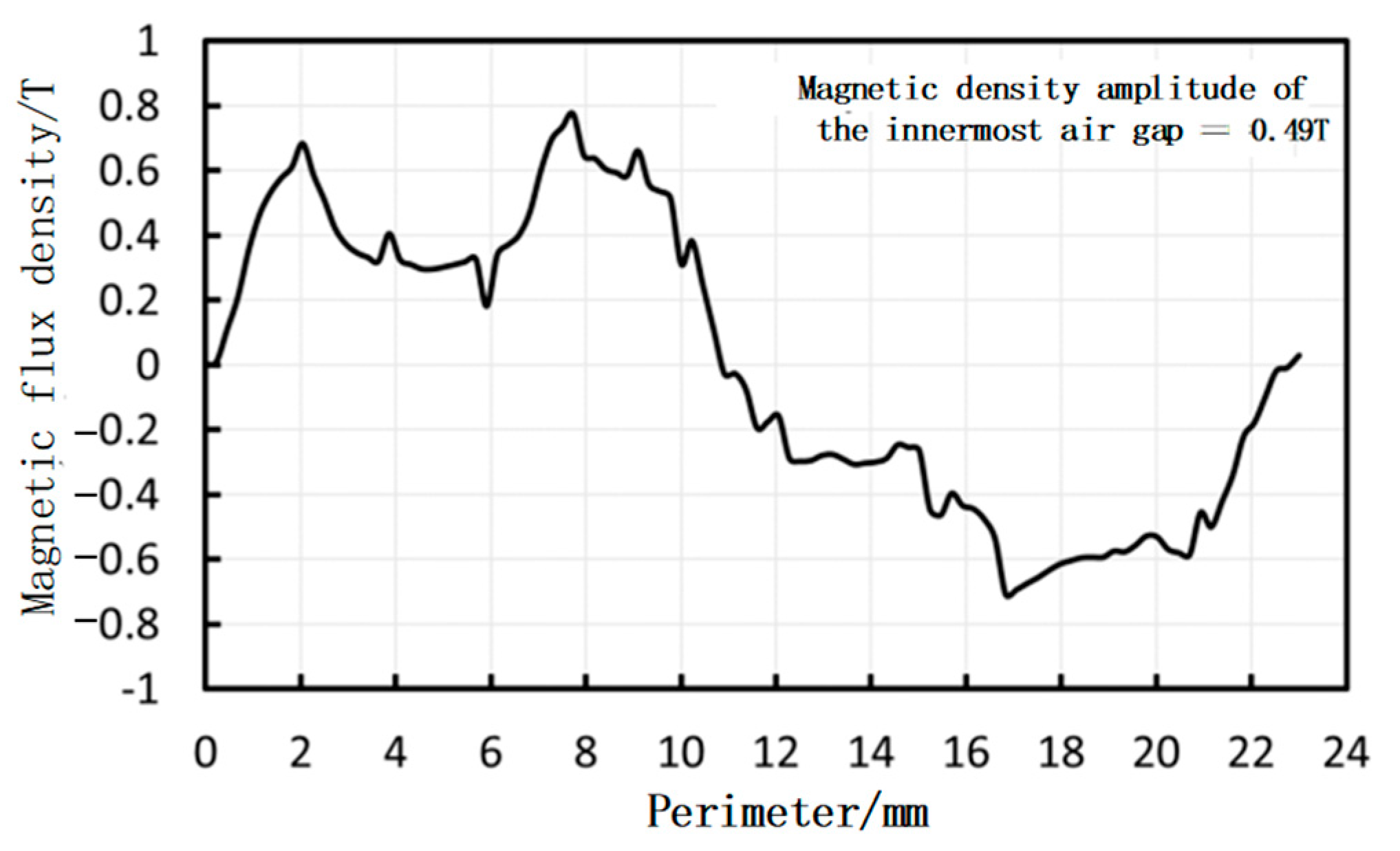
3.1. Static Magnetic Field Analysis

The magnetic flux density distribution of the stator core teeth in the axial flux motor is shown in Figure 3. The maximum magnetic flux density at the teeth is approximately 1.8 T. The magnetic flux density in the tooth part is relatively high, and there is a very small degree of magnetic field saturation. The first reason is that the stator tooth slotting and the tooth edge end effect cause obvious magnetic flux leakage. The second reason is the irregular mesh division uses tetrahedral elements. From the two-dimensional magnetic line distribution, it can be seen that the magnetic lines diffuse obviously at the edge of the tooth. Furthermore, the magnetic induction intensity in the middle of the tooth suddenly decreases. This is because the axial flux motor coil is three-phase powered, and the winding current directions of the two teeth are the same. Therefore, the magnetic flux is consistent in the vertical direction and opposite in the horizontal direction, resulting in a sudden decrease in the magnetic induction intensity in the middle of the tooth. Similarly, the magnetic flux density distribution of the rotor core, as shown in Figure 4, reaches a maximum of approximately 0.8 T. These results indicate that the rotor core’s magnetic flux density meets the design specifications.
The air gap flux density distribution of the axial flux permanent magnet motor is fan-shaped along the radius direction, as shown in Figure 5, and the partial air gap flux density in the circumferential direction is taken for analysis. In summary, the air gap flux density amplitude at the inner diameter of the motor is about 0.52 T, the air gap flux density amplitude at the middle average diameter is about 0.95 T, and the air gap flux density amplitude at the outer diameter is about 0.49 T. The air gap flux density distribution is reasonable. Three positions are selected for measuring an electrical cycle: =26.4 mm at the innermost diameter of the motor air gap, =31.8 mm at the average radius, and =36.2 mm at the outermost diameter. Measurements were carried out over one electrical cycle. The specific measurement positions are shown as line 1, line 2, and line 3 in Figure 6. The two dotted lines are the projections of line 2 and line 3 on the upper surface of the 3D motor model. The air gap flux density waveforms are shown in Figure 7, Figure 8 and Figure 9.

3.2. Transient Analysis

In this paper, the transient solver in the 3D module of Maxwell is employed to analyze the motor characteristics of the axial flux permanent magnet motor under different operating conditions. The material settings for each component of the axial flux permanent magnet motor are shown in Table 1.
First, the initial angle of the motor is set. It is necessary to calculate the angle through which the rotor needs to rotate to align the direct axis of the motor with the centerline of the A-phase winding. Then, this angle is set as the initial angle. Next, the band domain, which should enclose the rotor core and the permanent magnets, is configured. The band domain settings for the motor model are shown in Figure 10.
Next, the boundary conditions of the model are set. Since the computational load of the Maxwell 3D model is very large and the motor model designed in this paper is axially symmetric, a quarter model of the motor is used for simulation in this paper. This approach will significantly improve the simulation efficiency while ensuring the accuracy of the simulation results. The master–slave boundary conditions are adopted in this paper, and the master boundary conditions set for the three-dimensional motor model are shown in Figure 11.
The slave boundary conditions are shown in Figure 12.
The next step is to apply current excitations to the motor model. The following current source excitations are applied to each of the three-phase windings of the axial flux permanent magnet motor:
P h a s e A : 2 I r s i n ( π n 30 p t ) P h a s e B : 2 I r s i n ( π n 30 p t 2 3 π ) P h a s e C : 2 I r s i n ( π n 30 p t + 2 3 π )
where n is the rotational speed of the motor, Ir is the effective value of the loaded current, p is the number of pole pairs, and t is the simulation time.
Finally, when setting the solution conditions, the stop time for the solution is set to two electrical cycles, and the solution step size is set to perform 100 calculations per electrical cycle.
After completing the above steps, the transient field analysis of the axial flux permanent magnet motor is carried out.
The external characteristic curve of the motor, analyzed based on the working conditions of the quadruped robot, is shown in Figure 13. The rated torque is achieved at a speed of 1080 rpm, and the peak torque is reached at a speed of 900 rpm.

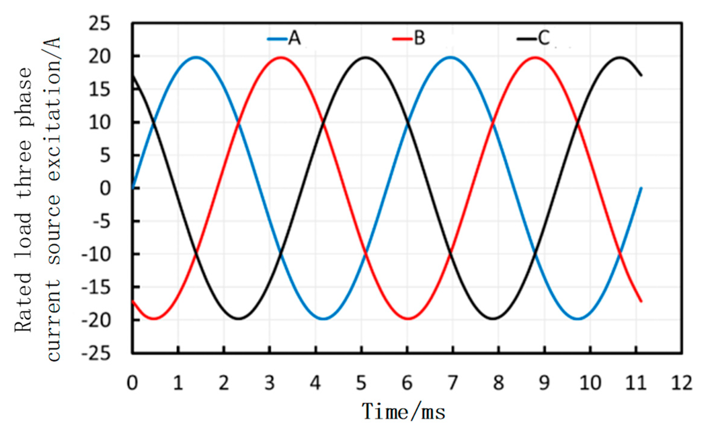
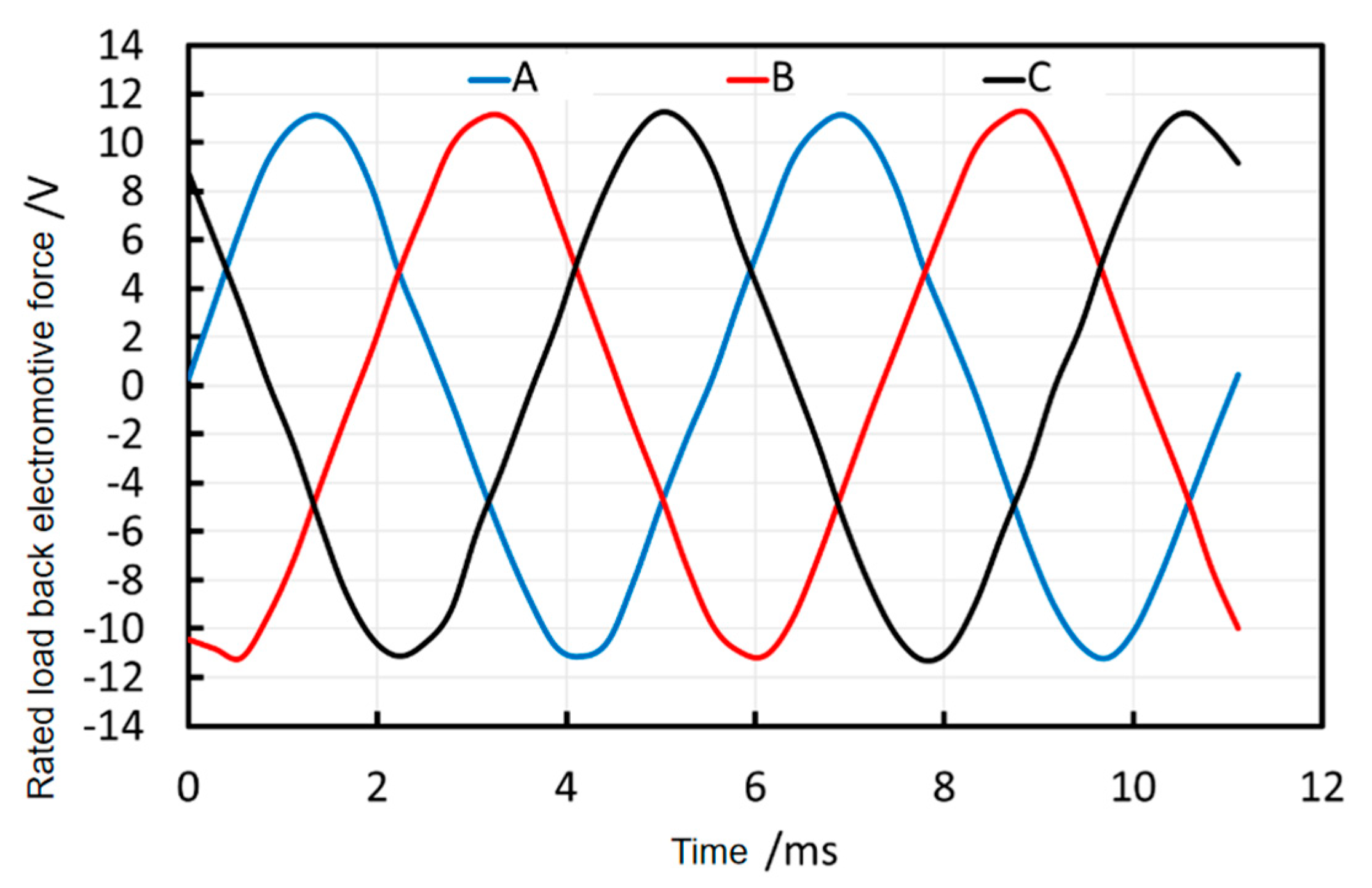
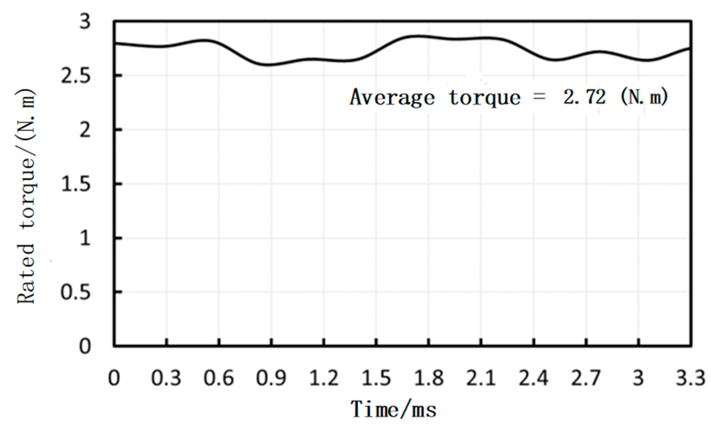
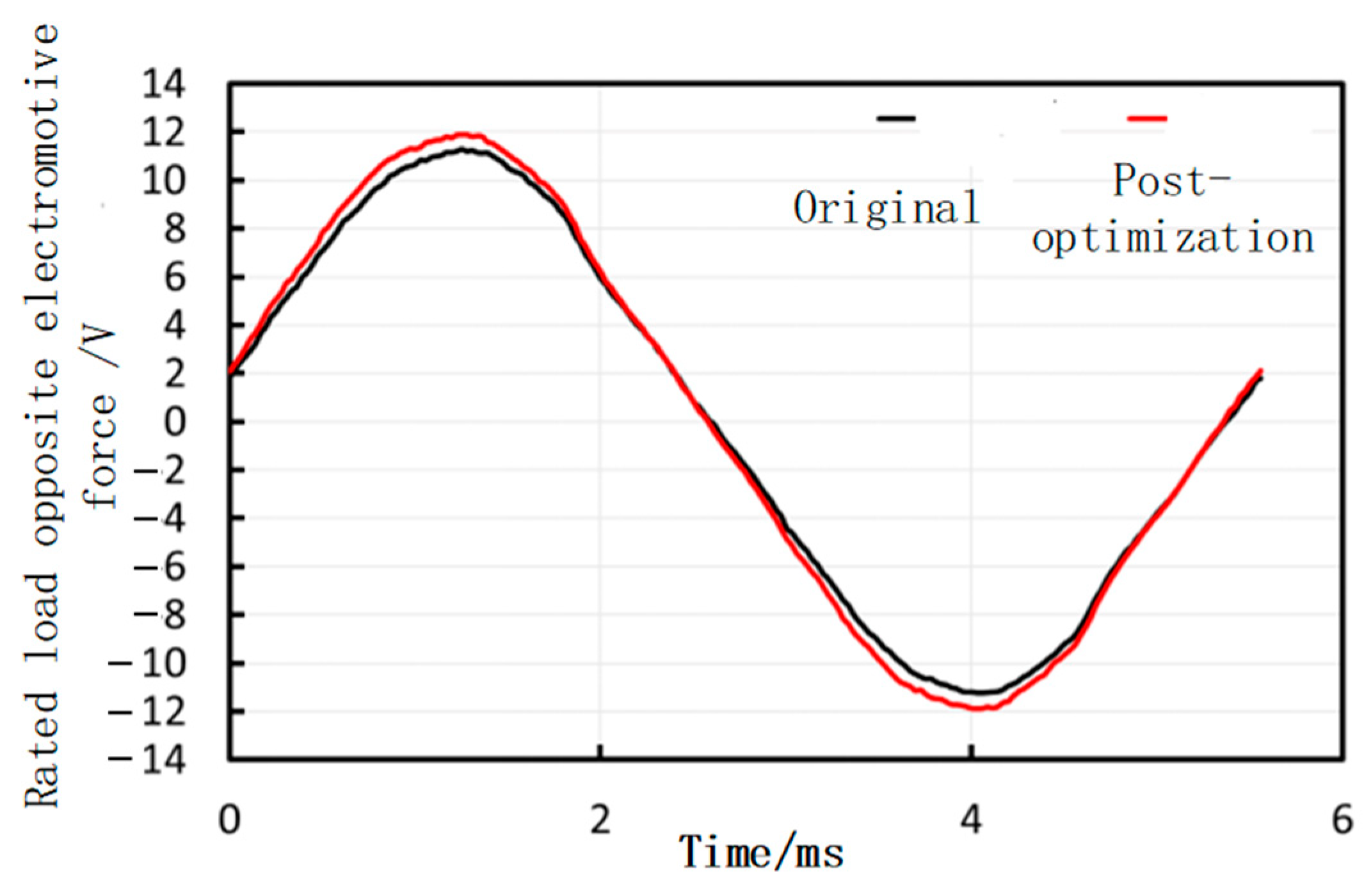
3.2.1. Rated Load Characteristics

When the rated torque is loaded, the RMS current flowing out from the power supply should be 14 A. Therefore, sinusoidal current source excitations with an RMS value of 14 A are applied to each of the three-phase windings of the axial flux permanent magnet motor, respectively, as shown in Figure 14. The simulated back electromotive force (EMF) under these conditions is presented in Figure 15, while the simulated output torque is shown in Figure 16. Both the motor’s speed and current remain stable during operation, and the back EMF and torque output are steady, meeting the motor’s design requirements.
In order to obtain the power calculation formula, the following formulas are solved simultaneously.
P = F · v
F = T R
v = 2 π R · n
where P is the output power (W), F is the force (N), v is the speed (m/s), T is the rated torque (N·m), R is the radius (m), and n is the rated speed (r/s). The output power is shown in the following formula:
P = T n 9550
where P is the output power (kW), T is the rated torque (N·m), n is the rated speed (rpm), and 9550 is a constant used to convert power (kW) and speed (r/min) into torque (N·m), which is the result of unit conversion and formula derivation. As shown in Figure 16, the rated torque reaches 2.7 N·m, corresponding to a rated speed of 1080 rpm. Based on the calculation, the motor’s output power under rated load conditions is approximately 0.305 kW, which satisfies the design requirements.

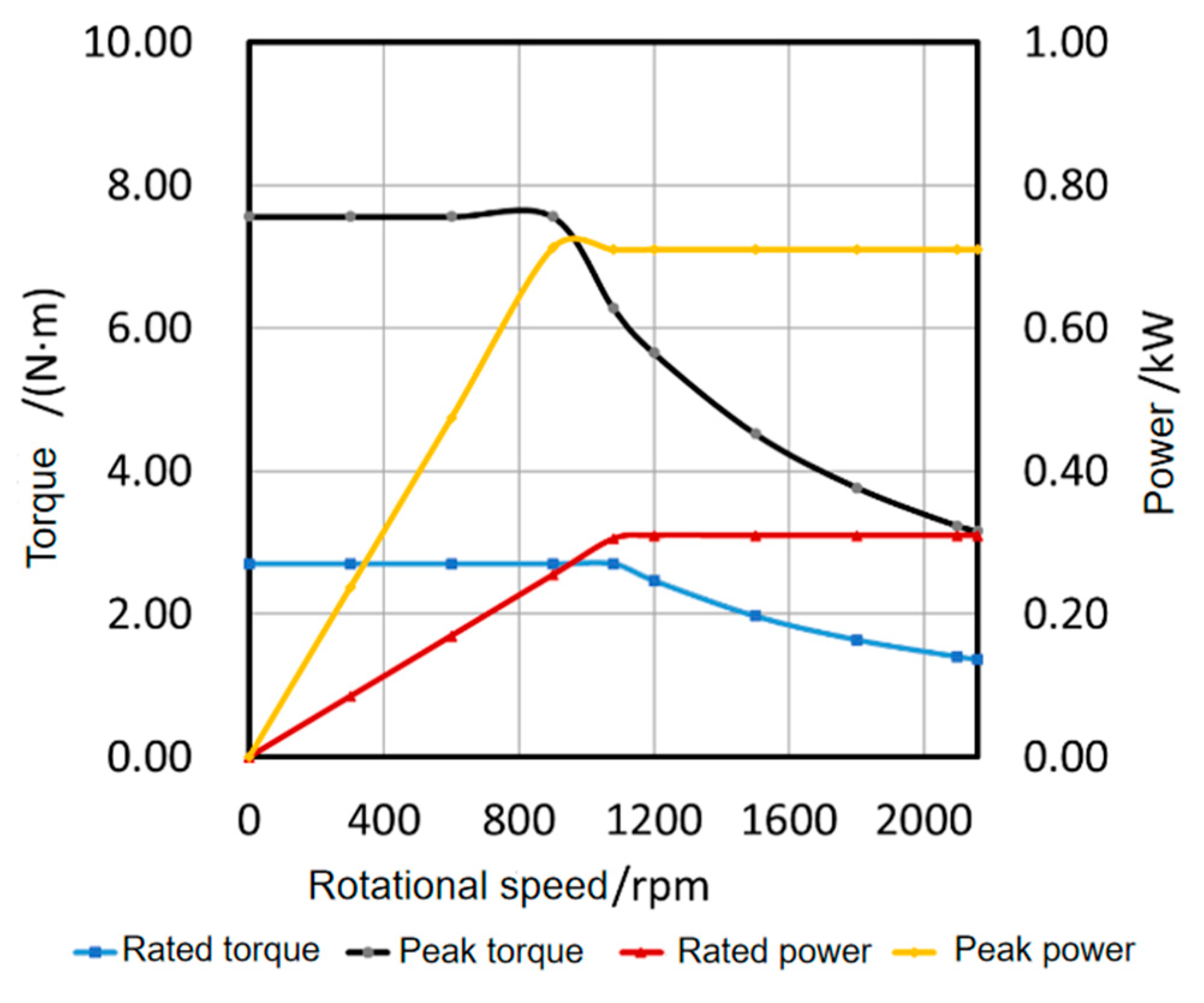
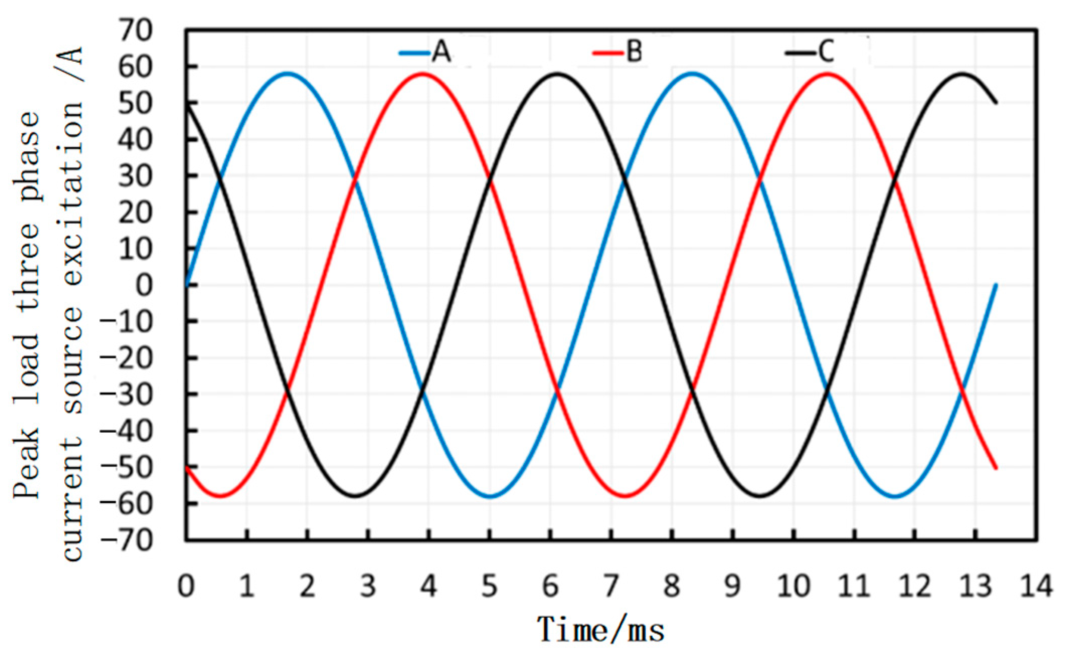
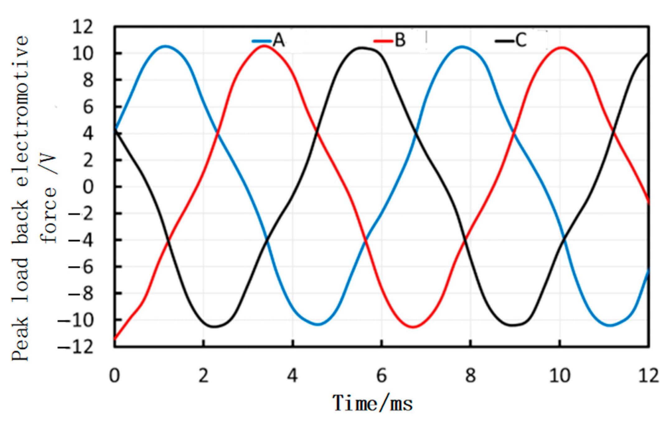
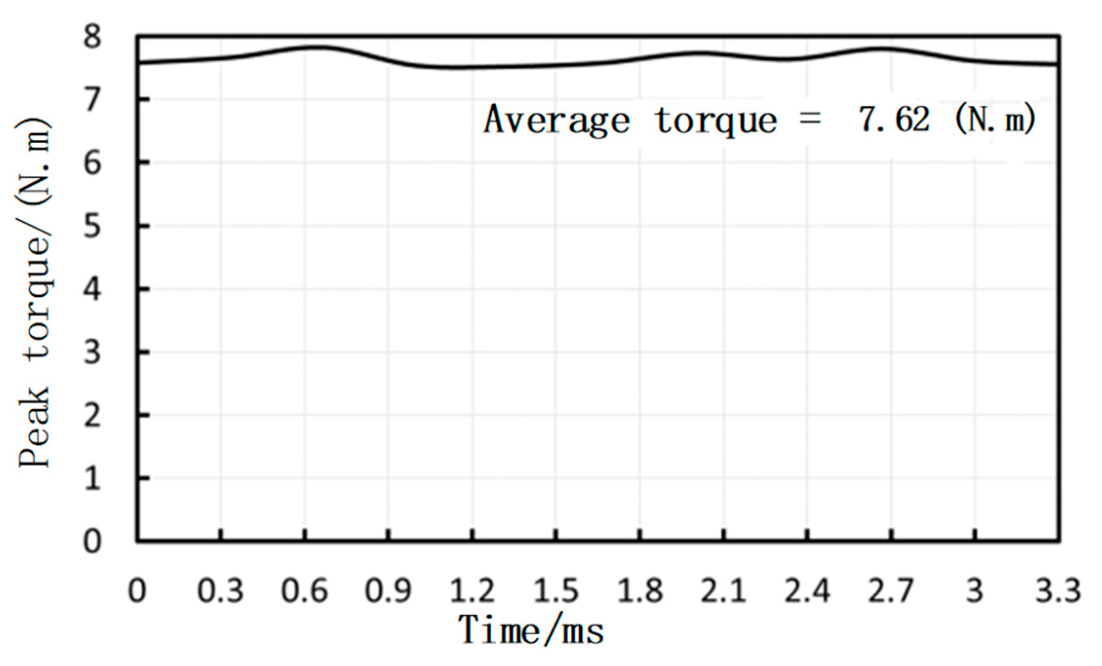
3.2.2. Peak Load Characteristics
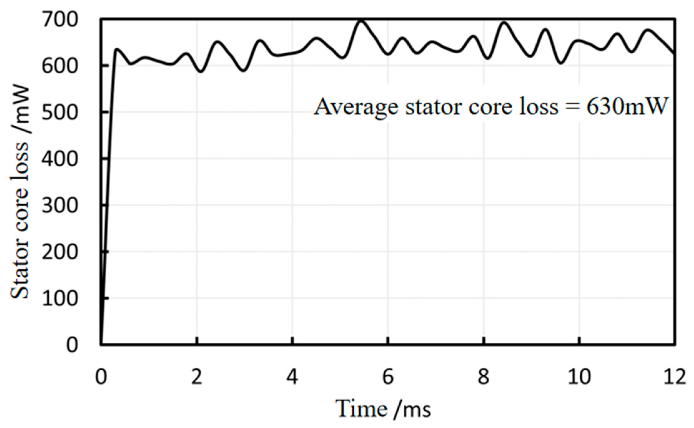
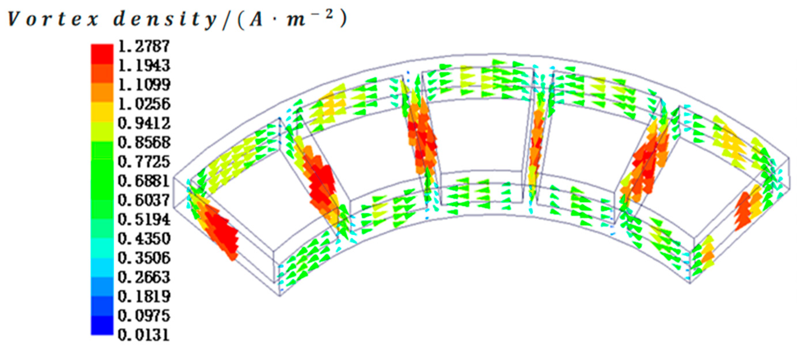
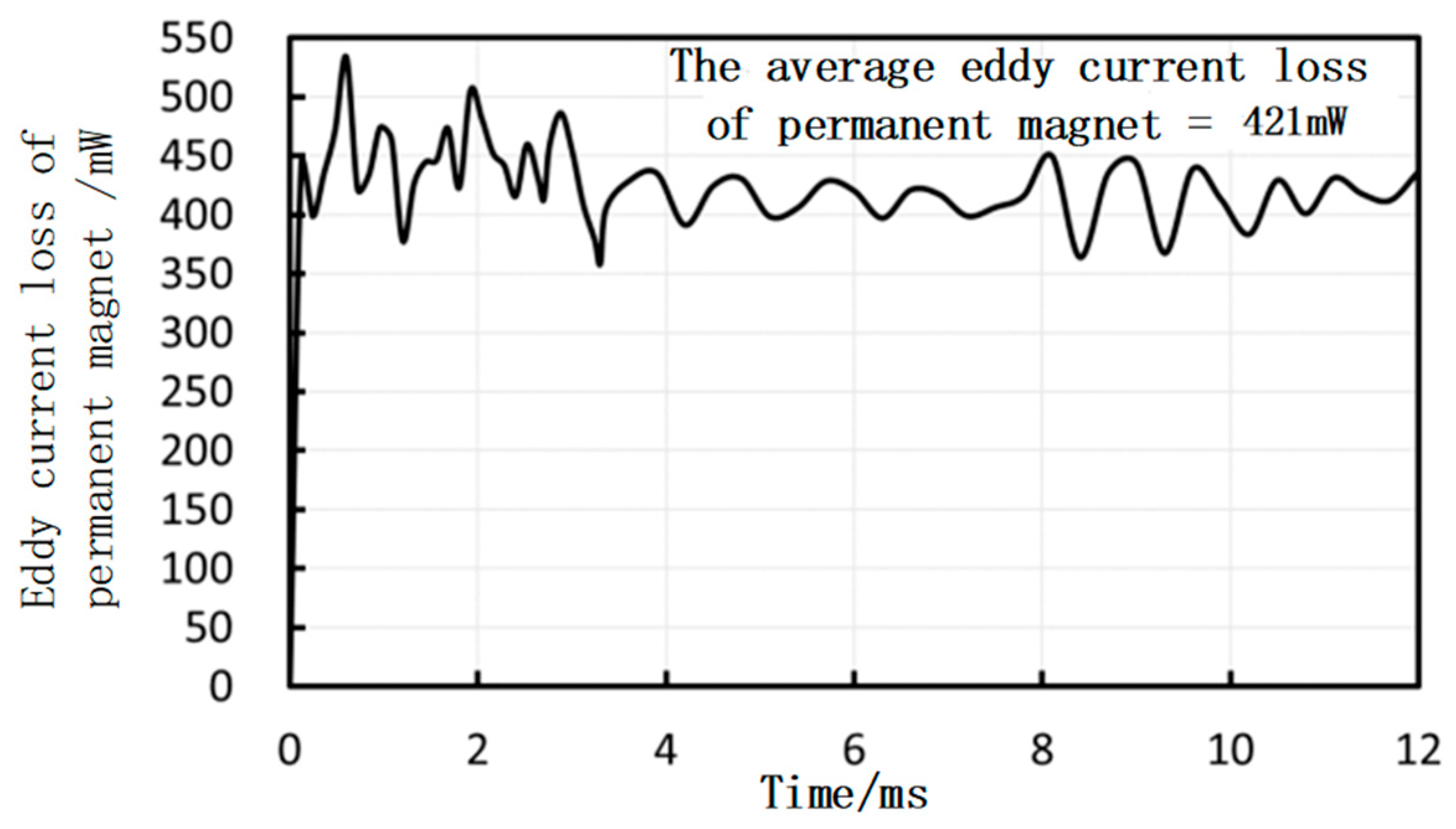
When the peak torque is loaded, the RMS current flowing out from the power supply should be 41 A. Therefore, sinusoidal current source excitations with an RMS value of 41 A are applied to each of the three-phase windings of the axial flux permanent magnet motor, respectively, as shown in Figure 17. The corresponding back EMF and output torque are presented in Figure 18 and Figure 19, respectively. Similar to the rated load conditions, the motor’s speed and current remain stable, and the back EMF and torque output of the motor are also stable, meeting the motor’s design specifications. As shown in Figure 19, the peak torque reaches 7.6 N·m at a speed of 900 rpm. The output power under peak load conditions is calculated using the formula:
P pt = T pt n pt 9550
where P pt is the output power (kW), T pt is the peak torque (N·m), and n pt is the speed (rpm). The resulting output power is approximately 0.716 kW, which is consistent with the motor’s rated power design of 0.7 kW.

3.3. Loss Analysis

The loss of the motor is the direct cause of its temperature rise. The temperature rise will affect the motor’s operational performance. The loss of the axial flux permanent magnet motor must be analyzed. In reference [24], losses were calculated using simplified empirical formulas and two-dimensional models. To achieve more precise loss calculations, this paper employs the Maxwell tensor method in combination with the three-dimensional finite element method and more accurate loss formulas for a detailed analysis. In this paper, the motor loss is calculated when the rated output power is 0.3 kW to verify that its efficiency is within a reasonable range. The stator core of the motor adopts the soft magnetic alloy material of 1J22, and the core loss will occur under the excitation of the sinusoidal alternating magnetic field of the winding. Core loss mainly includes hysteresis loss, eddy current loss, and additional loss. The basic formula of core loss, proposed by Bertotti, is as follows:
P Fe = P h + P c + P e
P h = k h · f · B m α
P c = k c · f 2 · B m 2
P e = k e · f 1.5 · B m 1.5
where P Fe is the total core loss and P h , P c , and P e represent the hysteresis, eddy current, and additional losses, respectively. The coefficients k h , k c , and k e denote the respective loss coefficients; f is the frequency; B m is the maximum magnetic flux density; and α is the core flux density coefficient.
Among them, the coefficients k h , k c , k e , and α are obtained by referring to the data of the 1J22 soft magnetic alloy material provided by the material supplier. Coefficients k h and α are variables related to the magnetic induction intensity.
The parameters of 1J22 soft magnetic alloy material are input into the software for calculation, and the core loss curve can be obtained. As shown in Figure 20, the stator core loss of the motor is about 630 mW.
The motor adopts a double-stator three-phase winding structure, so the winding loss is generated by the three-phase windings of the upper and lower stators. Due to the low speed of the axial flux permanent magnet motor, the high frequency magnetic field has little effect on the winding loss, and the additional winding loss caused by the skin effect can be ignored. The winding loss of the axial flux permanent magnet motor is as follows:
P Cu = m I 2 R AC
where P Cu is the winding loss, m is the number of winding phases, I is the RMS current, and R AC is the AC resistance of a single-phase winding. The AC resistance is given by the following:
R AC = k R · N l av σ S C
m Cu = ρ N l av S C
where k R is the resistance coefficient (it is a correction coefficient considering various factors, which can make up for the deviation of resistance calculation based on basic physical parameters to a certain extent), N is the number of turns of single-phase winding, l av is the average length of single turn, σ is the conductivity of the conductor, S C is the cross-sectional area of conductor, m Cu is the mass of conductor, and ρ is the density of conductor. The calculation formula of the winding loss of axial flux permanent magnet motor is obtained by introducing Equations (12) and (13) into Equation (11):
P Cu = m I 2 k R m Cu σ ρ S C 2 = m J 2 k R m Cu σ ρ
where J is the conductor current density, J = I / S C . The stator winding loss of the motor is about 33.31 W.
The motor rotor includes a rotor core and permanent magnet. The axial flux permanent magnet motor will produce induced electromotive force during operation. The periodic change of induced electromotive force will cause eddy current loss in both the rotor core and permanent magnet. Maxwell software is used to analyze the eddy current loss of the rotor core and the permanent magnet, respectively. The simulation conditions are consistent with those used for simulating the average torque values. The rotor core is modeled as a solid in the simulation process. The eddy current vector distribution of the rotor core is shown in Figure 21, and the eddy current vector distribution of the permanent magnet is shown in Figure 22.
During the solution process, rational mesh division will significantly enhance the solution accuracy. For the axial flux permanent magnet motor, the stator components are stationary parts with relatively low precision requirements; hence, larger-sized elements are used for meshing. The permanent magnets and rotor core are moving parts that require higher computational accuracy; thus, smaller-sized elements are selected. The air gap, being the core component where energy conversion takes place in the motor, demands extremely high computational accuracy. Very-small-sized mesh elements are chosen for the air gap, but the size should not be excessively small, otherwise the computational simulation process would become excessively lengthy. The remaining parts of the solution domain have lower accuracy requirements and can be meshed with relatively larger-sized elements.
Therefore, in the simulation mesh division, the stator uses a meshing unit with a length of 2 mm, the rotor and permanent magnet use a meshing unit with a length of 1mm, the air gap uses a meshing unit with a length of 0.5 mm, and the rest of the solution domain uses a meshing unit with a length of 4 mm. The meshing result is shown in Figure 23.
The core material of the rotor is stainless steel 304, and its conductivity is 1.4 × 10⁶ S/m. The conductivity of the rotor core is specified in the Maxwell transient solver to simulate the eddy current loss. The eddy current loss of the rotor core is shown in Figure 24, and it is about 113 mW. The permanent magnet material is N45SH, and its conductivity is 10−6 S/m. The conductivity of the permanent magnet is specified in the Maxwell transient solver to simulate the eddy current loss. The eddy current loss of the permanent magnet is shown in Figure 25, and it is about 421 mW.
There are two kinds of mechanical losses of axial flux permanent magnet motor. Bearing friction loss is related to the bearing speed, bearing type, and lubricant characteristics. Rotor wind friction loss is related to parameters such as coolant density and dynamic viscosity. It is difficult to accurately calculate the mechanical losses. According to the relevant research, the empirical formula of mechanical loss is as follows:
P f = P Bf + P Wf = ( 0.02 ~ 0.03 ) P out
where P f is the mechanical loss of the motor, P Bf is the friction loss of the bearing, P Wf is the wind friction loss of the rotor, and P out is the rated output power of the motor. When the rated output power of the axial flux permanent magnet motor is 300 W, the mechanical loss is about 7.5 W.
In summary, the loss of the electromagnetic components of the motor is shown in Table 2, and the calculation formula of the motor efficiency is as follows:
η = P out P out + ( P Fe + P Cu + P SE + P PME + P f )
where η is the motor efficiency, P SE is the eddy current loss of the rotor core, and P PME is the eddy current loss of the permanent magnet.
According to Equation (16), the efficiency of the axial flux permanent magnet motor is 87.73%.

4. Electromagnetic Torque Modeling and Torque Density Optimization

4.1. Electromagnetic Torque Model

The electromagnetic torque of axial flux permanent magnet motor can be calculated by the Maxwell tensor method, and the electromagnetic torque of the motor is as follows:
T e l e = 1 μ 0 R i R o r 2 0 2 π B n l _ x + B a r m _ x B n l _ y + B a r m _ y d θ d r
The above formula is further expanded to the following:
T e l e = 1 μ 0 R i R o r 2 0 2 π B tmp d θ d r
In Formula (18), B tmp is B n l x B n l y + B a r m x B a r m y + B n l _ x B a r m _ y + B a r m _ x B n l _ y , B n l _ x is the circumferential component of the no-load magnetic field density, B n l _ y is the axial component of the no-load magnetic field density, B n l _ x is the circumferential component of the armature reaction magnetic field density, and B n l _ y is the axial component of the armature reaction magnetic field density. Among them are the following:
B n l _ x B n l _ y = 0
B a r m _ x B a r m _ y = 0
The electromagnetic torque analytical model of the axial flux permanent magnet motor is obtained by introducing Equations (19) and (20) into Equation (18):
T e l e = 1 μ 0 R i R o r 2 0 2 π B n l _ x B a r m _ y + B a r m _ x B n l _ y d θ d r
It can be concluded that the electromagnetic torque of axial flux permanent magnet motor is related to the air gap length ( L t m / 2 ) , permanent magnet remanence B r , permanent magnet relative permeability μ r , permanent magnet magnetic field space harmonic number n, permanent magnet pole arc coefficient α p , permanent magnet thickness t m , motor pole distance τ p , motor stator slot width b 0 , motor slot distance τ s , motor stator core average radius R avg , distance between permanent magnet center and stator surface L , phase number m , motor stator slot number Z , each harmonic current amplitude I s , motor pole pair p , motor series turns per phase N p h , time harmonic number s , and space harmonic number v .

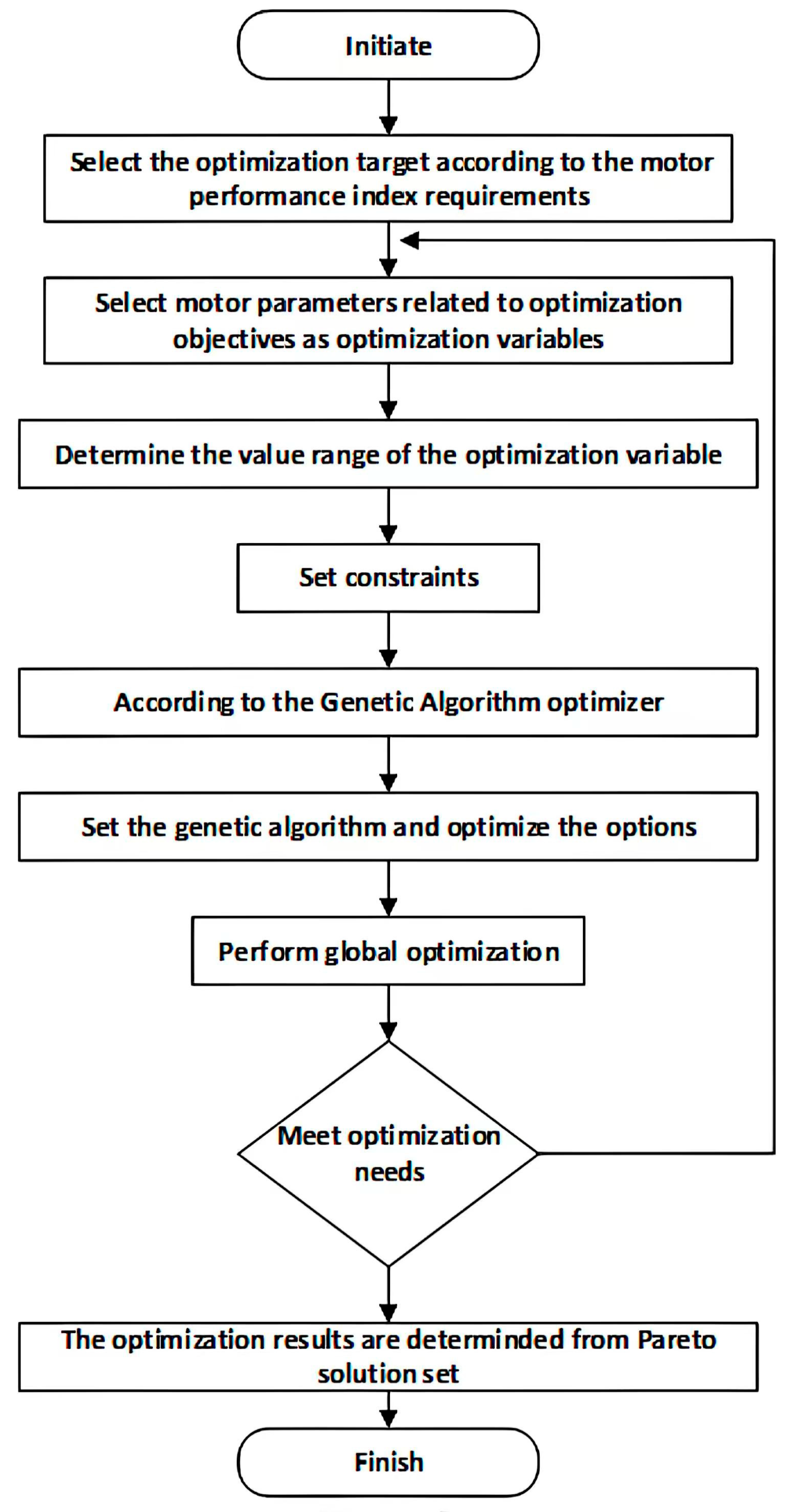
4.2. Torque Density Optimization

In this paper, the motor optimization variables are analyzed based on the electromagnetic torque analytical model. Using the genetic algorithm (GA) optimizer in Maxwell software, the motor optimization objectives are designed and refined. The detailed optimization process is illustrated in Figure 26.
Since the AFPMM designed in this paper is intended for use in quadruped robots, the motor is required to have a higher torque density. Therefore, the torque density of the motor is defined as the optimization objective in this paper, and its calculation formula is expressed as follows:
S = T ele _ avg m ele
In the formula, S represents the motor torque density, T ele _ avg is the average rated electromagnetic torque over an electric cycle, and m ele denotes the motor’s effective mass.
As can be seen from Equation (22), to enhance the torque density of the AFPMM, it is necessary to maximize the rated torque of the motor while minimizing its effective mass. Based on the electromagnetic torque analytical model of the axial flux permanent magnet motor, the stator slot width, stator slot depth, stator yoke thickness, and permanent magnet thickness affect the motor torque, while the air gap length influences the motor performance. First, an excessively narrow stator slot width leads to a smaller output electromagnetic torque. If the stator slot depth remains unchanged, it will increase the slot fill factor of the motor, thereby limiting the winding arrangement. However, an overly wide stator slot width can cause magnetic saturation in the teeth. Second, the stator yoke must be sufficiently thick to prevent magnetic saturation, but excessive thickness will increase the motor weight and reduce the torque density. Additionally, an excessively small air gap can cause magnetic saturation and rubbing between the rotor and stator (sweeping the chamber). An overly large air gap requires an increase in the permanent magnet thickness to maintain the electromagnetic torque, which in turn increases the motor weight. Lastly, the thickness of the permanent magnet affects the air gap magnetic field and electromagnetic torque. An increase in thickness raises the air gap magnetic flux density and electromagnetic torque. However, if the magnetic flux density in the stator yoke reaches saturation, the electromagnetic torque will stabilize. Therefore, the thickness of the permanent magnet needs to be optimized in conjunction with the thickness of the stator yoke.
The selected optimization variables include stator slot width b 0 , stator slot depth h s , stator yoke thickness h sy , permanent magnet thickness t m , and motor air gap length h g . Their respective value ranges are provided in Table 3, and their positions are shown in Figure 27.
During the optimization of the stator slot width and depth, the slot fill factor of the motor will be affected. An excessively high slot fill factor can increase the difficulty of winding or even make it impossible to wind the coils, while a low slot fill factor leads to material wastage. Therefore, the slot fill factor is set between 0.65 and 0.8. When optimizing the five parameters, the rated load back electromotive force (EMF) of the motor will also change. To ensure that the motor can reach its peak speed, the maximum value of the rated load back EMF should be limited to 0.35 to 0.45 times the rated voltage. During the optimization process, the magnetic flux densities in the stator yoke and teeth will also vary. Excessively high magnetic flux density in the yoke increases losses and heat generation, while a low magnetic flux density leads to material wastage. The motor designed in this paper uses 1J22 material, and the magnetic flux density in the yoke should be set between 1.35 and 1.45 T, while the magnetic flux density in the teeth should be set between 1.75 and 1.85 T. The optimization constraints are defined as follows:
0.65 K sf 0.8 0.35 U N 3 E l _ max 0.45 U N 1.35 T B sy 1.45 T 1.75 T B st 1.85 T
where K sf represents the slot full factor of the motor, E l _ max is the maximum counter electromotive force under rated load conditions, U N is the motor’s rated voltage (48 V in this paper), B sy denotes the magnetic flux density of the stator yoke, and B st denotes the magnetic flux density of the stator teeth.
The optimized motor model was established using Maxwell software. The transient simulation of the new motor finite element model was conducted, and the electromagnetic torque simulation results before and after optimization are compared in Figure 28. The results indicate that the average electromagnetic torque increases from 2.7 N·m before optimization to 3.2 N·m after optimization. The effective mass of the motor decreases from 0.606 kg to 0.599 kg, as summarized in Table 4. Based on these results and using formula (22), the torque density is calculated. Before optimization, the motor torque density is 4.45 N·m/kg, while after optimization, it improves to 5.34 N·m/kg, representing a 20% increase in torque density.
Transient simulation calculations were conducted on the new motor finite element model, resulting in the optimized motor’s rated load counter electromotive force waveform. Taking the counter electromotive force of phase A as an example, a comparison of the counter electromotive force under rated load conditions before and after optimization is shown in Figure 29. The maximum counter electromotive force under rated load conditions was 11.3 V before optimization and increased to 11.9 V after optimization, satisfying the specified constraint requirements. Static magnetic field simulations were also performed on the new motor finite element model. The optimized magnetic flux density of the stator yoke was determined to be 1.42 T, and that of the stator teeth was 1.83 T. Both values meet the required constraints.
The motor parameters and performance before and after optimization using the genetic algorithm based on the electromagnetic torque analytical model of the motor are summarized in Table 5. Following optimization, the torque density of the axial flux permanent magnet motor improves by 20%, with all constraint variables meeting the specified requirements. These results validate the effectiveness of the optimization algorithm.

5. Performance Testing

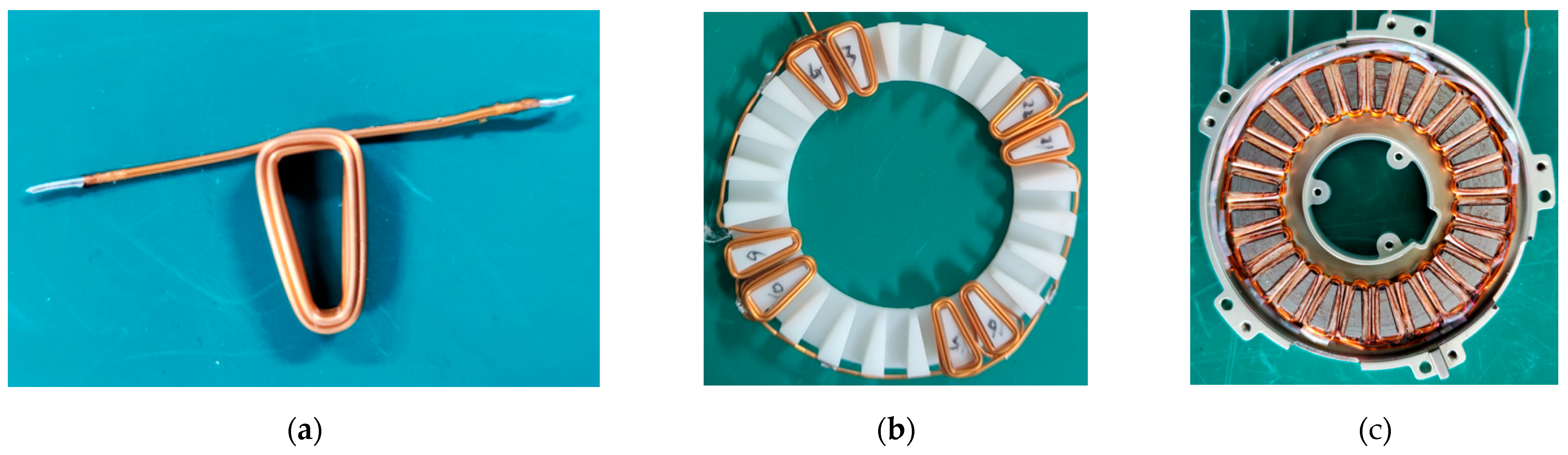
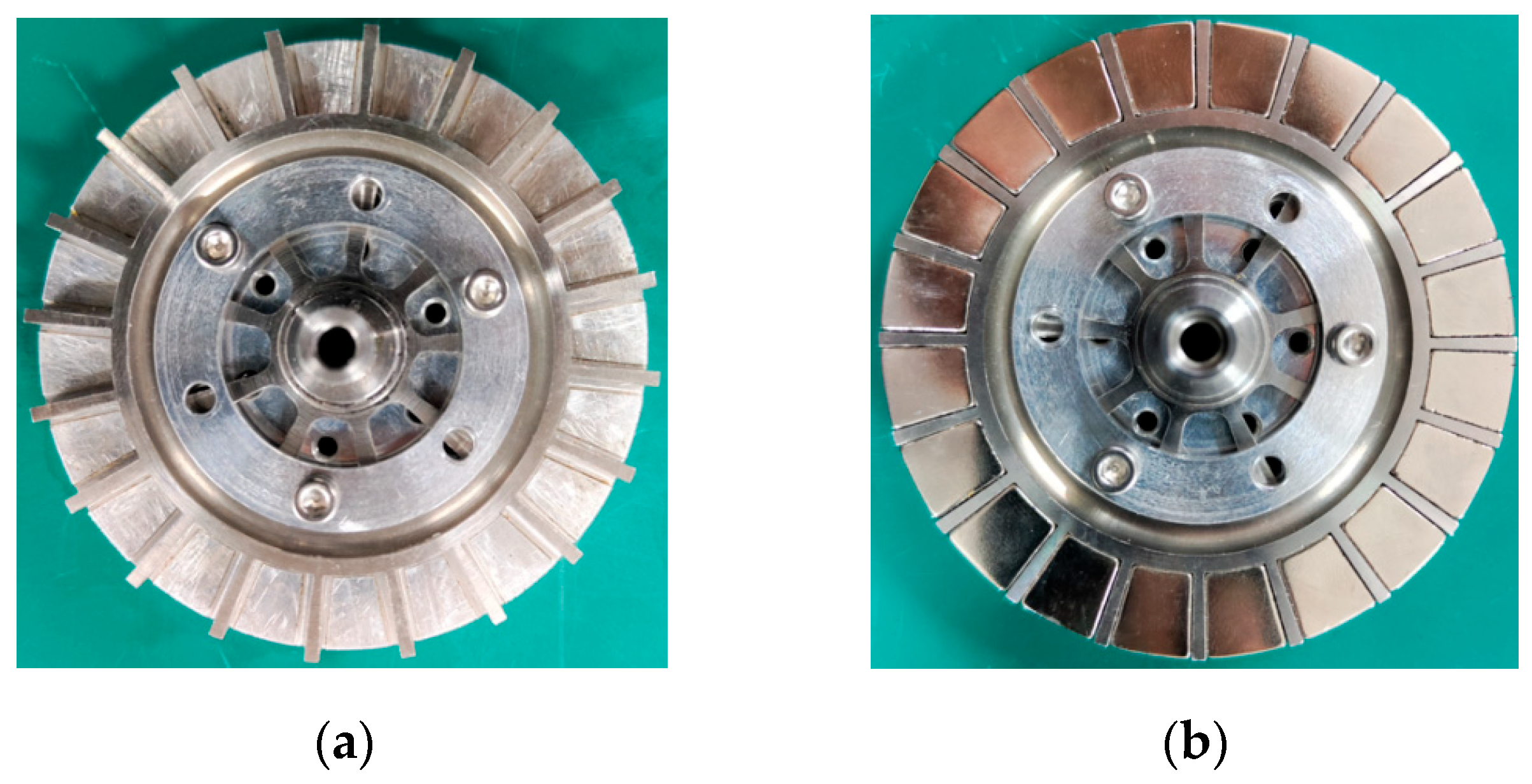
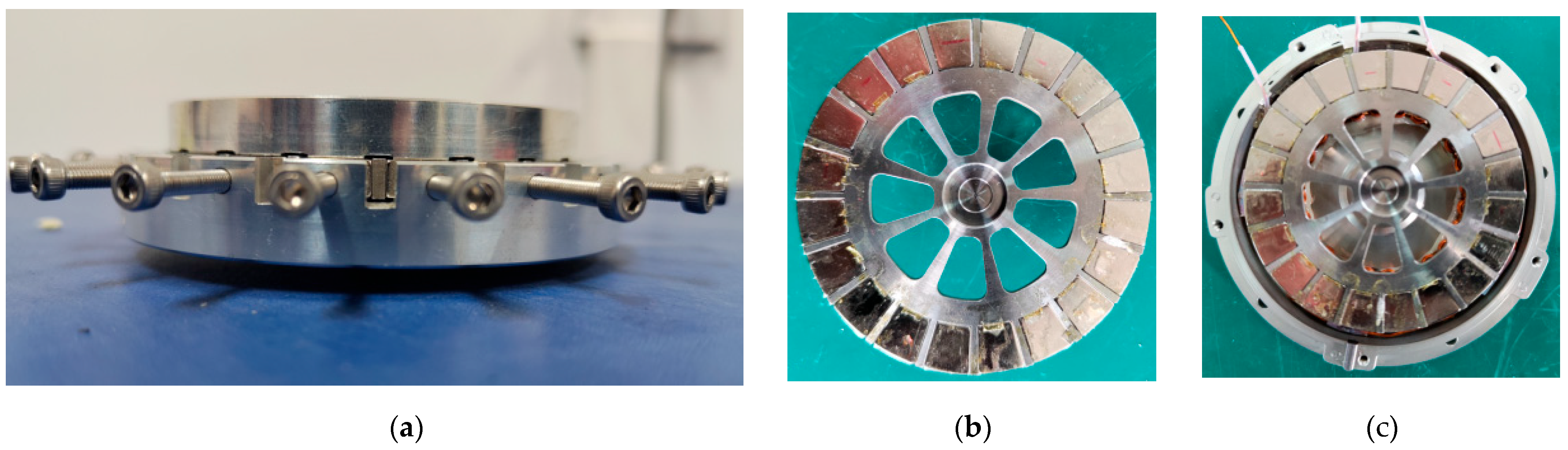
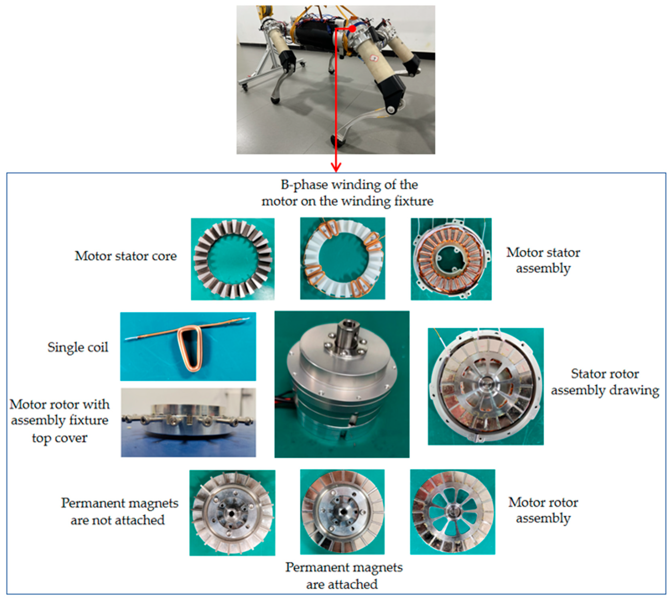
5.1. Principle Prototype Development
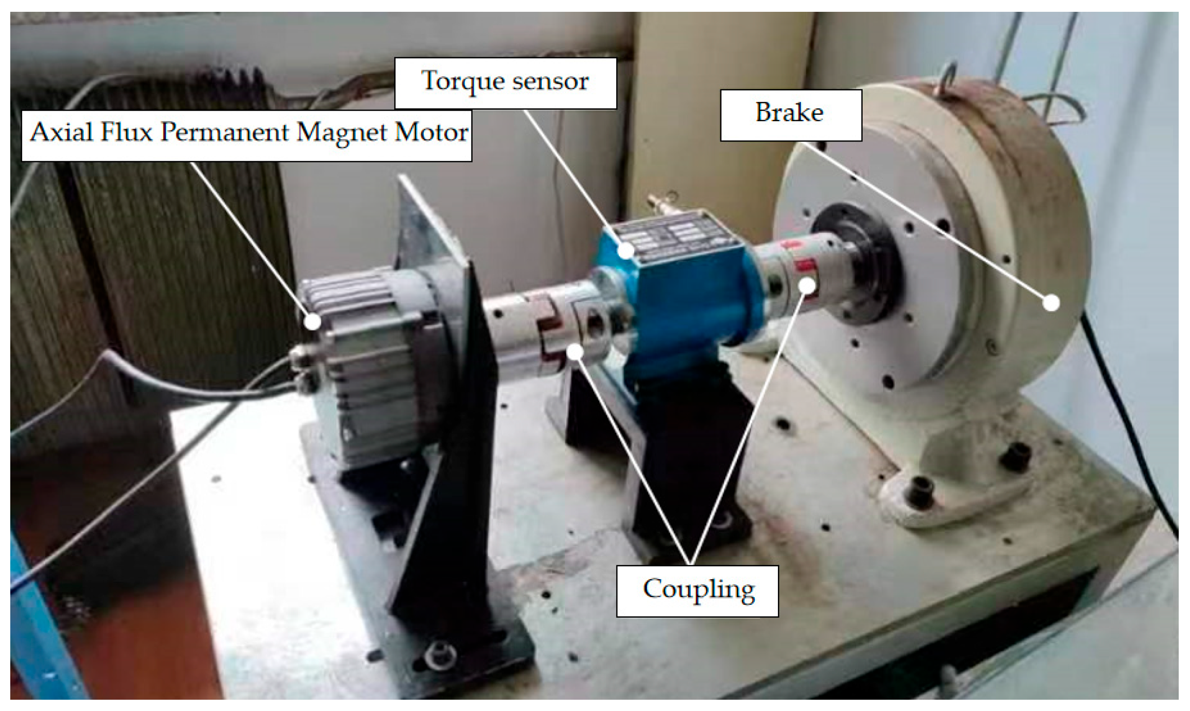
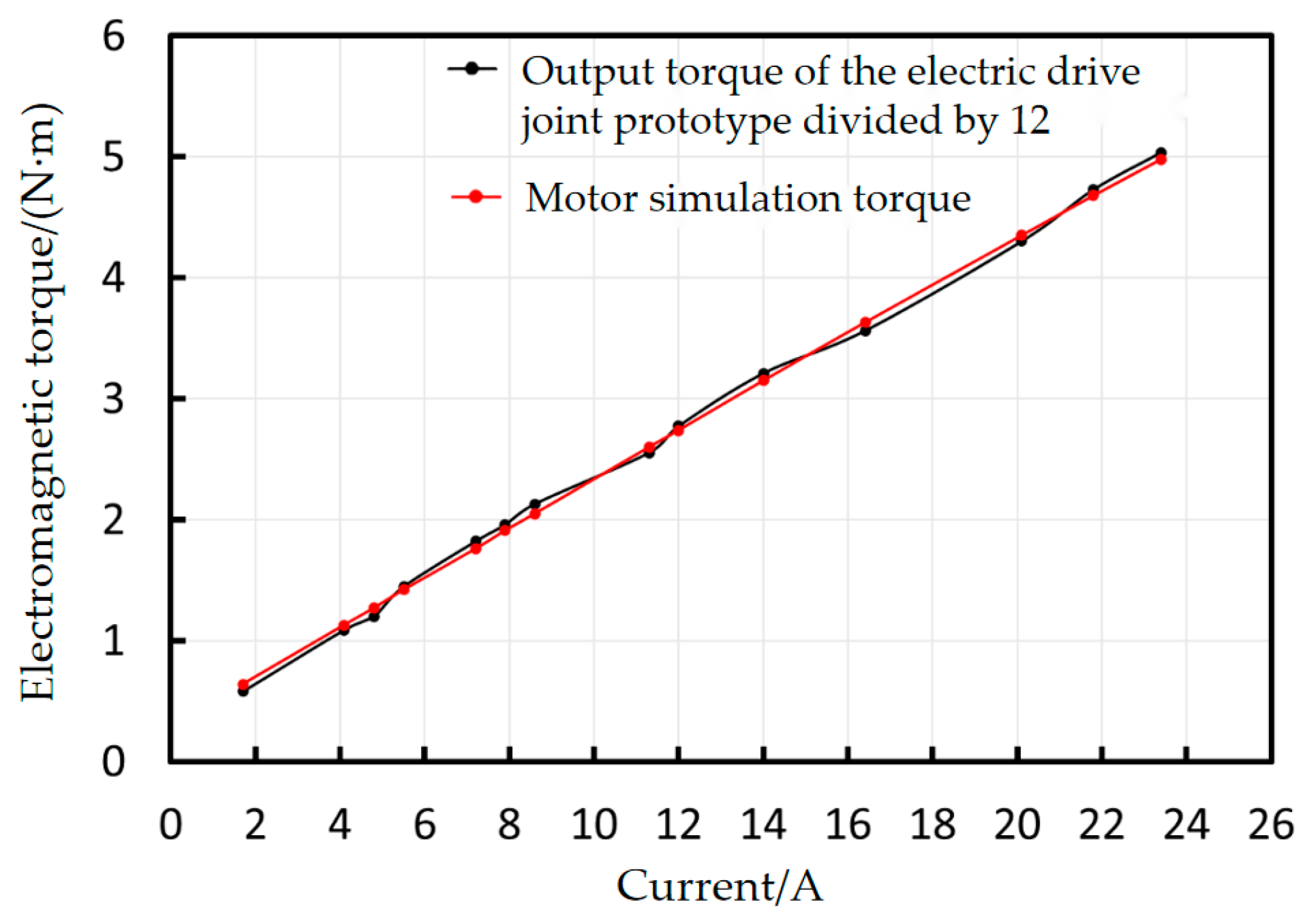
For the stator core processing of the axial flux permanent magnet motor, this paper employs a winding method. The process begins by fixing the 1J22 material of a specified width onto the material support mechanism. Since the 1J22 material tends to bend, it is directly sent to the leveling mechanism for flattening after passing through the support mechanism. Following this, the 1J22 material is slotted using a press. Finally, the slotted material enters the winding mechanism, where the automatic winding process is completed. The motor stator, processed through these steps, is shown in Figure 30.
For the windings of the axial flux permanent magnet motor, an automated winding process has been employed. It should be emphasized that although multi-wire winding was incorporated in the electromagnetic design, its practical implementation poses significant challenges. Therefore, in the finite element model, a single-wire equivalent was modeled by appropriately modifying the wire diameter and reducing the number of parallel winding wires to one, ensuring consistency in simulation results. In the actual manufacturing process, single-wire winding is implemented. Given the spatial constraints imposed by the motor’s compact size, each coil is initially wound individually on a dedicated fixture. Subsequently, coils belonging to the same phase are joined through welding to form the complete phase windings. An example of a single coil is shown in Figure 31a, while Figure 31b illustrates the B-phase windings after the winding and welding process on the fixture. Once all three-phase windings are completed, they are sequentially assembled onto the stator core, resulting in the stator assembly depicted in Figure 31c. Finally, the assembled windings undergo an immersion paint curing process to enhance their insulation properties and strengthen the stator assembly’s durability.
For the rotor of the motor, the rotor bracket, permanent magnets, assembly tooling base, and top cover are initially fabricated and prepared. Subsequently, the rotor is assembled by systematically integrating these components. The assembly process begins with positioning the rotor bracket onto the assembly tooling base. The permanent magnets are then arranged in accordance with the polarity configuration detailed in the electromagnetic design specifications. These magnets are secured to the rotor bracket using a specialized adhesive to ensure stability and alignment. Finally, the top cover of the assembly tooling is securely installed to complete the rotor assembly. Figure 32 illustrates the rotor prior to the installation of the top cover.
To verify and ensure the precise polarity of the permanent magnets, a milli-tesla meter is employed to measure and validate the magnetic poles prior to the installation of the top cover. Upon confirmation of the polarity, the top cover is precisely installed, and bolts are secured to provisionally stabilize the magnets. The assembly is then subjected to oven heating to facilitate the curing of the adhesive between the magnets and the rotor bracket. Figure 33a illustrates the motor rotor before heating, while Figure 33b depicts the rotor assembly after the curing process. Utilizing structural components such as the spindle, bearings, end cover, and casing, the stator assembly and rotor assembly are axially assembled, with the winding leads routed out, as shown in Figure 33c. The fully assembled electric drive joint is illustrated in Figure 34.

5.2. Torque Test

The designed electric drive joint is characterized by high torque density, and its torque performance is specifically tested. The torque test platform, shown in Figure 35, consists of the axial flux motor, a torque sensor, a coupling, a brake, and a host computer. The brake simulates the motor load, while the axial flux motor drives this load through the coupling. The torque sensor captures the torque and current data of the electric drive joint prototype and transmits it to the host computer for real-time monitoring and recording.
At the beginning of the test, the rotational speed of the electric drive joint prototype is stabilized at the rated speed of 1080 rpm by controlling the input frequency. Subsequently, the input current is increased in fixed increments, and the torque on the motor’s output shaft is directly measured by the torque sensor. The relationship between the current and the output torque is recorded by the host computer. The results are shown in Figure 36. Under the rated current, the output torque of the electric drive joint meets the design requirements, and the output torque exhibits good linearity with the input current. This indicates that no magnetic circuit saturation occurs within the tested current range, verifying the effectiveness of the motor design.
To validate the accuracy of the simulation results, the torque–current relationship of the electric drive joint prototype is compared with the simulation data. Since the electric drive joint incorporates a reducer with a reduction ratio of 12, the output torque of the prototype is divided by 12 before comparison. The comparison is illustrated in Figure 37. The close agreement between the simulation data and prototype measurements confirms the accuracy of the finite element simulation.

6. Conclusions

This paper proposes an axial flux permanent magnet motor designed specifically for the electric drive joints of mechanical dogs, with a rated speed of 1000 rpm. The topology and key structural parameters of the AFPMM were analyzed, and a three-dimensional electromagnetic model was developed based on the electromagnetic design. Electromagnetic field simulations were conducted using Maxwell software. The results indicate that the stator core flux density and air gap flux density distributions are well designed. The AFPMM achieves a rated output torque of 2.72 N·m and a peak torque of 7.52 N·m. A comprehensive loss analysis was performed, and the overall efficiency was calculated to be 85.36%. A prototype was built to validate the simulation results and structural parameters, offering a novel approach for designing axial flux motors with high torque density and high power density.

Author Contributions

Conceptualization, D.Q. and C.H.; methodology, H.W.; software, C.L. and H.W.; validation, X.Y. and M.L.; formal analysis, D.Q. and C.H.; investigation, Y.Z. and H.W.; resources, L.M. and Y.Z.; data curation, C.L. and L.M.; writing—original draft preparation, D.Q. and C.H.; writing—review and editing, M.L.; visualization, C.L. and Z.Z.; supervision, Z.Z. and X.Y.; project administration, D.Q. and L.M.; funding acquisition, L.M. and Y.Z. All authors have read and agreed to the published version of the manuscript.

Funding

This work was supported by the Foundation of Chinese State Key Laboratory of Robotics and Systems (Grant No. SKLRS202413B), the Foundation of National Key Laboratory of Aerospace Mechanism, China (Grant No. 2024ASH-ZY05), the National Natural Science Foundation of China (Grant No. 52405257), the China Postdoctoral Science Foundation (Grant No. 2024M764201), the Postdoctoral Fellowship Program (Grade B) of China Postdoctoral Science Foundation (Grant No. GZB20240955), and the Natural Science Foundation of Heilongjiang Province, China (Grant No. LH2024E029).

Institutional Review Board Statement

Not applicable.

Informed Consent Statement

Not applicable.

Data Availability Statement

Data is contained within the article.

Conflicts of Interest

The authors declare no conflicts of interest.

References

  1. Kaliyev, V.; Helwig, A.; Ahfock, T. Axial flux PM coreless stator machine development for low sp eed wind generator. In Proceedings of the 2017 Australasian Universities Power Engineering Conference (AUPEC), Melbourne, Australia, 19–22 November 2017; pp. 1–6. [Google Scholar]
  2. Eser, E.; Üstkoyuncu, N. Design and Analysis of a Novel Axial Flux Permanent Magnet Assisted Synchronous Reluctance Motor. J. Electr. Eng. Technol. 2024, 1–10, prepublish. [Google Scholar] [CrossRef]
  3. Kahourzade SMahmoudi, A.; Ping, H.W. A Comprehensive Review of Axial-Flux Permanent-Magnet Machines. Can. J. Electr. Comput. Eng. 2014, 37, 19–33. [Google Scholar] [CrossRef]
  4. Park, W.S.; Moon, H.J.; Kang, W.D.; Su, K.H. A Study on Enhancing Axial Flux Motor Efficiency Using Cladding Core Technology. Mathematics 2024, 12, 2981. [Google Scholar] [CrossRef]
  5. Augusto, A.; Caetano, E.R. Design of a Yokeless double disc axial flux motor for light electric vehicles. Frankl. Open 2024, 8, 100166. [Google Scholar] [CrossRef]
  6. Parada, G.A.; Valle, D.M.F.; Tous, B.R. Design and Construction of a Multipole Electric Motor Using an Axial Flux Configuration. World Electr. Veh. J. 2024, 15, 256. [Google Scholar] [CrossRef]
  7. Yim, W.; Yoon, J.; Cha, J.; Bong, U.; Hahn, S. A design study on 20 kW class axial flux motor with HTS field winding for 100 MPa liquid hydrogen pump. Cryogenics 2024, 139, 103829. [Google Scholar] [CrossRef]
  8. Jiujian, C.; Kaijie, Y.; Yuhao, D.; Lu, X. Design and Optimization of a Novel External-Rotor Axial Flux Motor for In-Wheel Application. J. Electr. Eng. Technol. 2024, 19, 2473–2479. [Google Scholar]
  9. Jiujian, C.; Chen, W. Electromagnetic thermal coupling analysis for a novel cooling system of an axial flux hub motor. IET Electr. Power Appl. 2021, 16, 421–433. [Google Scholar]
  10. Chelarem, B.D.; Bilal, A.; Elhadj, A.; Felseghi, R.A.; Filote, C.; Dumitrescu, C.; Raboaca, M.S. Design Development and Analysis of a Partially Superconducting Axial Flux Motor Using YBCO Bulks. Materials 2021, 14, 4295. [Google Scholar]
  11. Laitram, L.L.C. Patent Issued for Axial Flux Motor For A Conveyor (USPTO 10,723,562). J. Eng. 2020, 6472. [Google Scholar]
  12. Gieras, J.F.; Gieras, I.A. Performance analysis of a coreless permanent magnet brushless motor. In Proceedings of the 2002 IEEE Industry Applications Conference. 37th IAS Annual Meeting (Cat. No.02CH37344), Pittsburgh, PA, USA, 13–18 October 2002; pp. 2477–2482. [Google Scholar]
  13. Gieras, J.F.; Wang, R.J.; Kamper, M. Axial Flux Permanent Magnet Brushless Machines; Springer: New York, NY, USA, 2008; pp. 29–34. [Google Scholar]
  14. Ahmed, D.; Ahmad, A. An optimal design of coreless direct-drive axial flux permanent magnet generator for wind turb ine. In Proceedings of the 6th Vacuum and Surface Sciences Conference of Asia and Australia (VASSCAA-6), Islamabad, Pakistan, 9–13 October 2012. J. Phys. Conf. Ser. 2013, 439, 012039. [Google Scholar] [CrossRef]
  15. Credo, A.; Tursini, M.; Villani, M.; Di Lodovico, C.; Orlando, M.; Frattari, F. Axial Flux PM In-Wheel Motor for Electric Vehicles: 3D Multiphysics Analysis. Energies 2021, 14, 2107. [Google Scholar] [CrossRef]
  16. Hong, K.M.; Pyo, J.H.; Song, W.S.; Jung, D.H.; Kim, W.H. A Study on the Improvement of Power Density of Axial Flux Motors for Collaborative Robot Joints through Same-Direction Skew. Machines 2023, 11, 591. [Google Scholar] [CrossRef]
  17. Tiegna, H.; Amara, Y.; Barakat, G. Study of Cogging Torque in Axial Flux Permanent Magnet Machines Using an Analytical Model. IEEE Trans. Magn. 2014, 50, 845–848. [Google Scholar] [CrossRef]
  18. Polikarpova, M.; Lindh, P.; Gerada, C.; Rilla, M.; Naumanen, V.; Pyrhönen, J. Thermal effects of stator potting in an axial-flux permanent magnet synchronous generator. Appl. Therm. Eng. 2015, 75, 421–429. [Google Scholar] [CrossRef]
  19. Yang, Y.P.; Shih, G.Y. Optimal Design of an Axial-Flux Permanent-Magnet Motor for an Electric Vehicle Based on Driving Scenarios. Energies 2016, 9, 285. [Google Scholar] [CrossRef]
  20. Darabi, A.; Baghayip, M.; Mirzahosseini, R. An Extended Analytical Algorithm for Optimal Designing of a TORUS-type Non-slotted Axial-Flux Permanent Magnet Motor. J. Control Autom. Electr. Syst. 2017, 28, 748–761. [Google Scholar] [CrossRef]
  21. Zhao, J.; Hua, M.; Liu, T. Research on a Sliding Mode Vector Control System Based on Collaborative Optimization of an Axial Flux Permanent Magnet Synchronous Motor for an Electric Vehicle. Energies 2018, 11, 3116. [Google Scholar] [CrossRef]
  22. Kutt, F.; Blecharz, K.; Karkosiński, D. Axial-Flux Permanent-Magnet Dual-Rotor Generator for a Counter-Rotating Wind Turb ine. Energies 2020, 13, 2833. [Google Scholar] [CrossRef]
  23. Wang, H.; Zeng, X.; Eastham, F.J.; Pei, X. Axial Flux Permanent Magnet Motor Topologies Magnetic Performance Comparison. Energies 2024, 17, 401. [Google Scholar] [CrossRef]
  24. Ge, W.; Xiao, Y.; Cui, F.; Wu, X.; Liu, W. Optimization Comparison of Torque Performance of Axial-Flux Permanent-Magnet Motor Using Differential Evolution and Cuckoo Search. Actuators 2024, 13, 255. [Google Scholar] [CrossRef]
Figure 1. The overall schematic diagram of the axial flux motor.
Applsci 15 03327 g001
Figure 2. Axial flux motor schematic.
Applsci 15 03327 g002
Figure 3. Magnetic flux density distribution contour of stator teeth in axial flux motor.
Applsci 15 03327 g003
Figure 4. Cloud map of magnetic flux density distribution of motor rotor core.
Applsci 15 03327 g004
Figure 5. Motor air gap magnetic flux density distribution diagram.
Applsci 15 03327 g005
Figure 6. Schematic of air gap magnetic flux density measurement positions in axial flux motor.
Applsci 15 03327 g006
Figure 7. The magnetic flux density distribution of the air gap at the innermost diameter of 26.4 mm of the motor air gap.
Applsci 15 03327 g007
Figure 8. The magnetic flux density distribution of the air gap at the average radius of the motor air gap, which is 31.8 mm.
Applsci 15 03327 g008
Figure 9. The magnetic flux density distribution of the air gap at the outermost radius of 36.2 mm of motor air gap.
Applsci 15 03327 g009
Figure 10. Axial flux permanent magnet motor band domain setting diagram.
Applsci 15 03327 g010
Figure 11. Motor main boundary setting diagram.
Applsci 15 03327 g011
Figure 12. Motor setting diagram from boundary conditions.
Applsci 15 03327 g012
Figure 13. External characteristic curve of axial flux permanent magnet motor.
Applsci 15 03327 g013
Figure 14. The three-phase winding current source of the motor is excited under the rated load condition.
Applsci 15 03327 g014
Figure 15. The opposite electromotive force of the motor under rated load conditions.
Applsci 15 03327 g015
Figure 16. The output torque of the motor under rated load conditions.
Applsci 15 03327 g016
Figure 17. The three-phase winding current source of the motor is excited under peak load conditions.
Applsci 15 03327 g017
Figure 18. The opposite electromotive force of the motor under peak load conditions.
Applsci 15 03327 g018
Figure 19. The output torque of the motor under peak load conditions.
Applsci 15 03327 g019
Figure 20. Motor stator core loss.
Applsci 15 03327 g020
Figure 21. Eddy current vector distribution in the rotor core.
Applsci 15 03327 g021
Figure 22. Eddy current vector distribution in permanent magnet.
Applsci 15 03327 g022
Figure 23. Manual meshing result of axial flux permanent magnet motor: (a) full model; (b) quarter model.
Applsci 15 03327 g023
Figure 24. Eddy current loss in rotor core.
Applsci 15 03327 g024
Figure 25. Eddy current loss in permanent magnet.
Applsci 15 03327 g025
Figure 26. Optimization process of axial flux permanent magnet motor.
Applsci 15 03327 g026
Figure 27. Schematic diagram of some structural parameters of axial flux permanent magnet motor.
Applsci 15 03327 g027
Figure 28. Optimized front and rear motor electromagnetic torque comparison diagram.
Applsci 15 03327 g028
Figure 29. Optimized front and rear motor load rated opposite electromotive force comparison diagram.
Applsci 15 03327 g029
Figure 30. Motor stator core.
Applsci 15 03327 g030
Figure 31. Coil winding and assembly: (a) single coil; (b) B-phase winding of the motor on the winding fixture; (c) motor stator assembly.
Applsci 15 03327 g031
Figure 32. Motor rotor without assembly fixture top cover: (a) permanent magnets are not attached; (b) permanent magnets are attached.
Applsci 15 03327 g032
Figure 33. Parts of the motor: (a) the motor rotor with assembly fixture top cover; (b) the motor rotor assembly; (c) the stator rotor assembly drawing.
Applsci 15 03327 g033
Figure 34. Physical prototype of electric drive joints.
Applsci 15 03327 g034
Figure 35. Electric joint prototype test platform.
Applsci 15 03327 g035
Figure 36. Torque–current diagram of electric drive joint prototype.
Applsci 15 03327 g036
Figure 37. Comparison diagram of torque–current relationship between electric drive joint prototype and motor simulation.
Applsci 15 03327 g037
Table 1. Material settings for each component of the motor.
Motor ComponentMaterial Name
Permanent magnetN45SH
Rotor coreStainless steel 304
Stator core1J22
Stator windingCopper
Table 2. Motor electromagnetic component loss table.
Loss NameParameter ValueUnit
Stator core loss0.63W
Stator winding loss33.31W
Eddy current loss of rotor core0.11W
Eddy current loss of permanent magnet0.42W
Mechanical loss7.5W
Table 3. Optimize the range of values of variables.
Parameter NameParameter RangeUnit
W i d t h   o f   s t a t o r   n o t c h   b 0 4.5~5.5mm
Stator groove depth h s 4.9~5.9mm
Thickness of stator yoke h sy 1.6~2.6mm
T h i c k n e s s   o f   p e r m a n e n t   m a g n e t   t m 4.5~5.5mm
Motor air gap length h g 0.3~0.7mm
Table 4. Optimized front and rear motor effective mass comparison table.
NameQuantityPre-Optimized WeightOptimized WeightUnit
Stator core20.2880.284kg
Winding480.2540.254kg
Permanent magnet200.0640.061kg
Gross weight10.6060.599kg
Table 5. Motor parameters and performance comparison table.
Parameter NameBefore OptimizationPost-OptimizationUnit
Width of stator notch b 0 54.8mm
Stator groove depth h s 5.45.2mm
Thickness of stator yoke h sy 2.12mm
Thickness of permanent magnet t m 54.8mm
Air gap length h g 0.50.4mm
Slot filling rate K sf 0.680.74/
Opposite maximum electromotive force E l _ max 11.311.9V
Stator   yoke   is   magnetically   dense   B sy 1.41.42T
S t a t o r   t e e t h   a r e   m a g n e t i c a l l y   d e n s e   B st 1.81.83T
Average electromagnetic torque T ele _ avg 2.73.2N.m
Effective mass m ele 0.6060.599kg
Torque density S 4.455.34N.m/kg
Disclaimer/Publisher’s Note: The statements, opinions and data contained in all publications are solely those of the individual author(s) and contributor(s) and not of MDPI and/or the editor(s). MDPI and/or the editor(s) disclaim responsibility for any injury to people or property resulting from any ideas, methods, instructions or products referred to in the content.

