1. Introduction
Millimeter-wave FMCW radar is emerging as an effective technology for sensing applications, particularly in the field of small displacement measurement, such as respiration detection, vibration detection, or bridge displacement detection [
1]. With advancements in integrated semiconductor technology, the performance of millimeter-wave radar sensors has significantly improved recently, enabling their application in critical machine vibration sensing, where detecting extremely small displacements is crucial.
Machine vibration sensing, commonly known as condition-based monitoring (CbM), has gained popularity as a proactive maintenance strategy [
2]. Traditionally, accelerometers have been used to measure small vibrations [
3,
4]. However, as contact-based sensors, accelerometers present certain challenges. For instance, the mass of the sensor itself may alter the vibration characteristics of the target, making it less suitable for specific applications. In such cases, contactless vibration sensing techniques, such as millimeter-wave radar, offer a viable alternative.
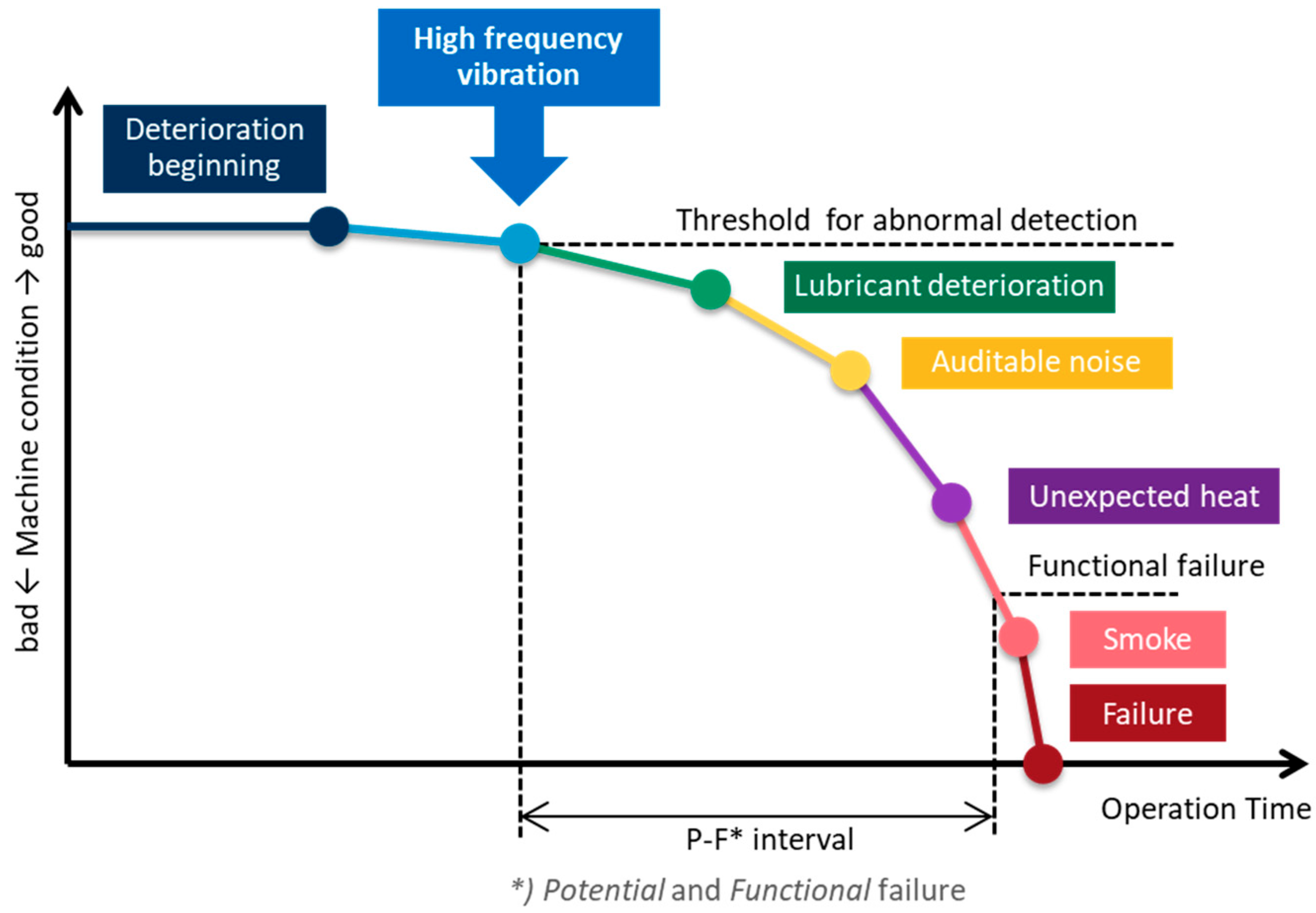
In the context of machine vibrations related to deterioration, the P-F (Potential Failure–Functional Failure) curve, shown in
Figure 1, is widely discussed in the CbM engineering field [
5]. The P-F curve tracks machine deterioration through various indicators, including vibration, over the operational period. Detecting vibrations in the early stages of deterioration is crucial, as characteristic changes often emerge during this period [
6]. Early detection is essential for timely maintenance. For example, bearing fault monitoring requires detecting high-frequency vibrations, as these serve as critical diagnostic features. A motor rotating at 880 rpm can generate vibrations exceeding 10 kHz in the frequency spectrum [
7], which must be detected by sensors.
For sinuous vibrations, the displacement (D [mm]) is determined by acceleration (A [g]) and vibration frequency (f [Hz]), as expressed in Equation (1). As the equation indicates, higher vibration frequencies correspond to smaller displacements, necessitating sensor systems capable of detecting extremely small displacement ranges.
Among contactless displacement sensing techniques, optical laser sensors are one of the feasible options for precise displacement measurement. Several studies have employed optical laser sensors to measure small displacements. To achieve extreme sensor accuracy, a photonic FMCW radar architecture has been proposed, in which the chirped signal generator and dechirp modulation are implemented using a photonic circuit, while the RF frontend is based on a microwave and millimeter-wave transceiver circuit [
8]. Since the photonic circuit offers lower phase noise, higher chirp linearity, and significantly wider bandwidth [
9], ultra-high accuracy can be achieved in small displacement measurements, reaching the sub-micron or nanometer range. However, this system requires more complex components and a much higher-speed analog frontend circuit (e.g., a high-speed A/D converter). Furthermore, in condition-based monitoring (CbM) of machines, vibration amplitudes typically range from millimeters to micrometers, making RF-based FMCW radar sufficiently accurate while allowing for a simplified circuit, such as a single integrated MMIC. Additionally, RF frontends can operate reliably in harsh and dusty environments, and RF-based circuits offer greater stability under such conditions.
As for studies on RF radar sensor accuracy, several studies have validated the accuracy and precision of radar sensors for small vibration or displacement measurements using controlled experimental setups. For instance, mechanical linear sliders or actuators have been used to provide well-defined displacements while radar sensors detect the target’s position [
10,
11,
12]. However, in such cases, measurement accuracy depends on the precision of the mechanical system, which includes components such as motors, metal arms, and reflectors in a complex structure. Consequently, scale errors may arise, which are difficult to isolate.
To mitigate such scale errors, some studies employed optical laser displacement sensors as reference sensors for radar measurements [
13]. When two sensors (i.e., radar and laser sensor) are used, precise alignment between the sensors and target (e.g., a reflector) is critical, as even a slight angular misalignment can introduce micrometer-scale errors. To resolve alignment issues, an experimental apparatus was developed in which both sensors were linearly aligned on a mechanical linear slider system to minimize misalignment caused by angular offsets [
14]. Additionally, the setup was built on a solid granite slab to isolate it from environmental influences. This configuration achieved an accuracy of ±4.5 μm while other limitations, such as thermal expansion and mechanical alignment errors, were also addressed. Furthermore, another study controlled environmental factors such as air temperature, relative humidity, air pressure, and carbon dioxide concentration to improve radar measurement accuracy, achieving ±0.1 μm accuracy, which reached the limit of reference laser sensor accuracy of ±0.4 μm [
15].
Further improvements in measurement accuracy require an alternative setup beyond the limitations of the reference laser sensor. Moreover, previous studies did not fully examine MMIC phase accuracy and precision due to circuit characteristics.
In FMCW radar-based vibration monitoring, the phase characteristics of beat signals between consecutive FMCW chirps are directly linked to displacement accuracy and precision [
16]. Therefore, phase accuracy and precision are critical parameters for radar sensors in detecting small displacements.
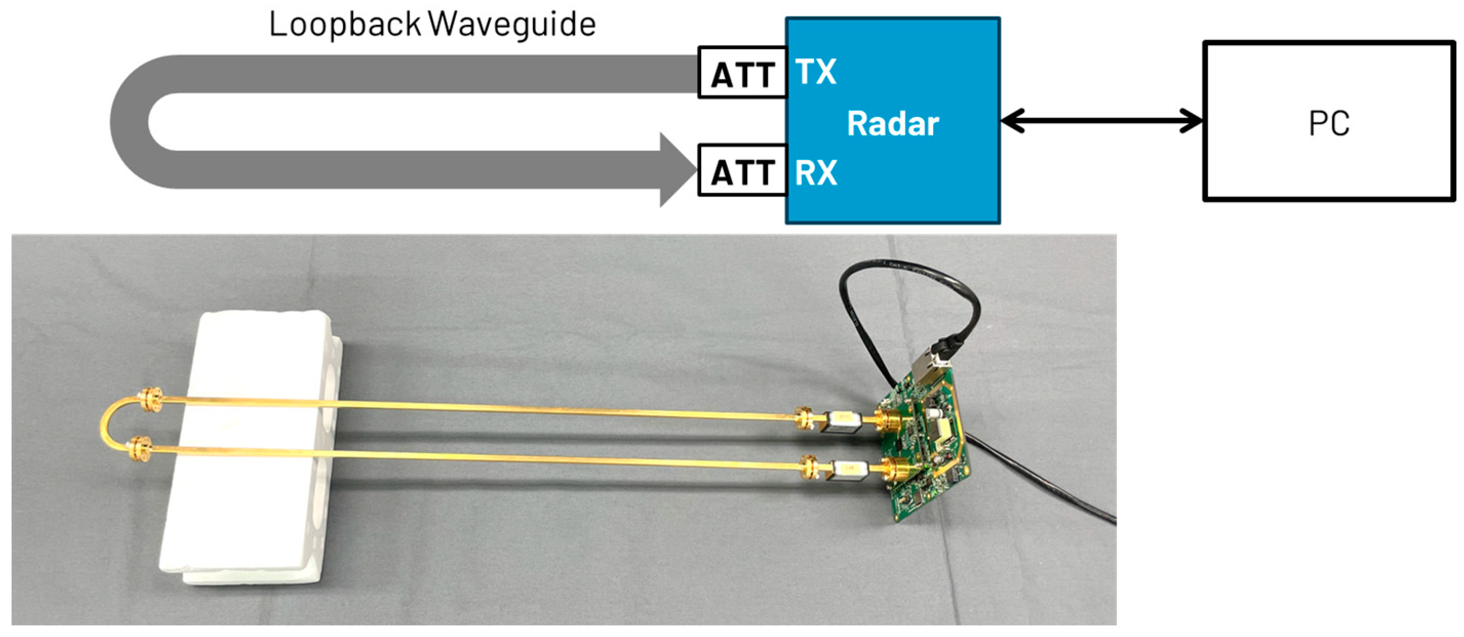
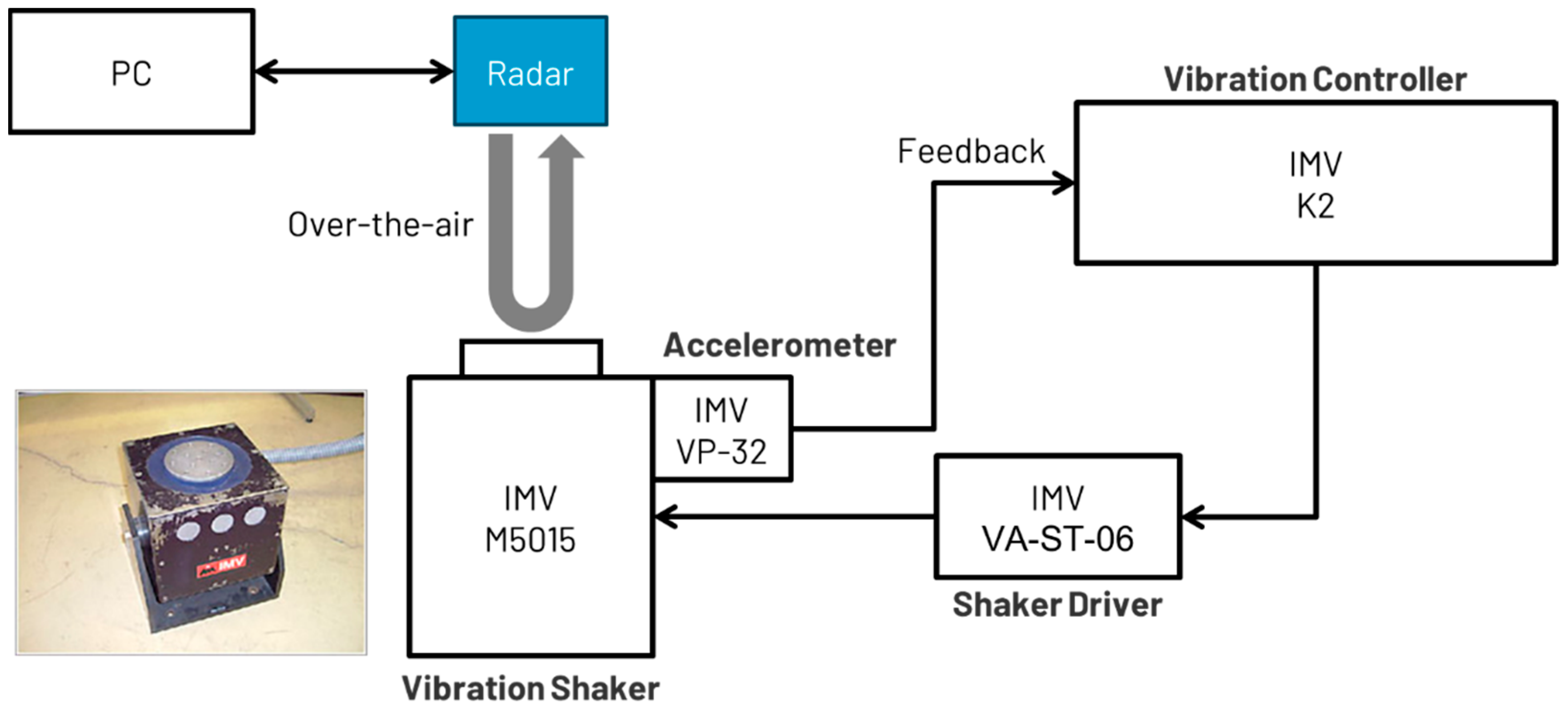
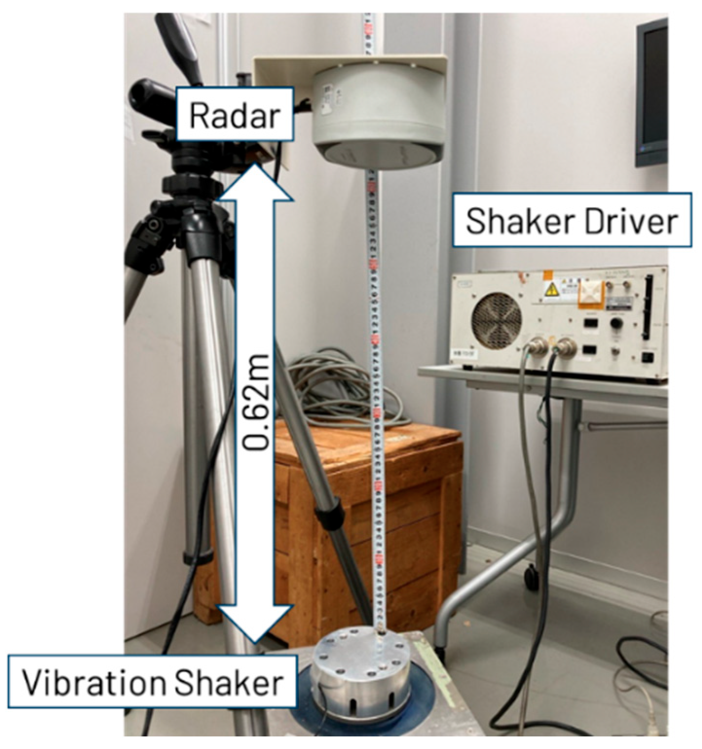
This study aims to address the gap in precise micrometer-scale displacement measurement using FMCW radar through controlled experiments with enhanced methodologies. Unlike previous studies, this research employs a novel loopback waveguide testing method to provide a stable radar target free from environmental influences. Two experiments were conducted to evaluate the radar system’s phase accuracy and precision. The first experiment focused on fundamental phase measurements using a loopback waveguide to evaluate the inherent phase accuracy and precision of the MMIC, independent of environmental factors. The second experiment measured actual displacements in free space using an industrial vibration shaker, which enables precise displacement control and is widely used in the development of commercial industrial products. The methodologies and findings presented in this paper contribute to the advancement of next-generation sensing technologies, establishing a new standard for precision in vibration monitoring using FMCW radar.
This paper is organized as follows:
Section 2 introduces the radar signal processing algorithm for machine vibration and small displacement sensing.
Section 3 details the experimental setup for phase accuracy and precision measurements.
Section 4 presents the results of the two experiments, followed by a discussion in
Section 5. Finally,
Section 6 concludes this paper.
2. Phase Estimation Algorithm for Displacement Monitoring
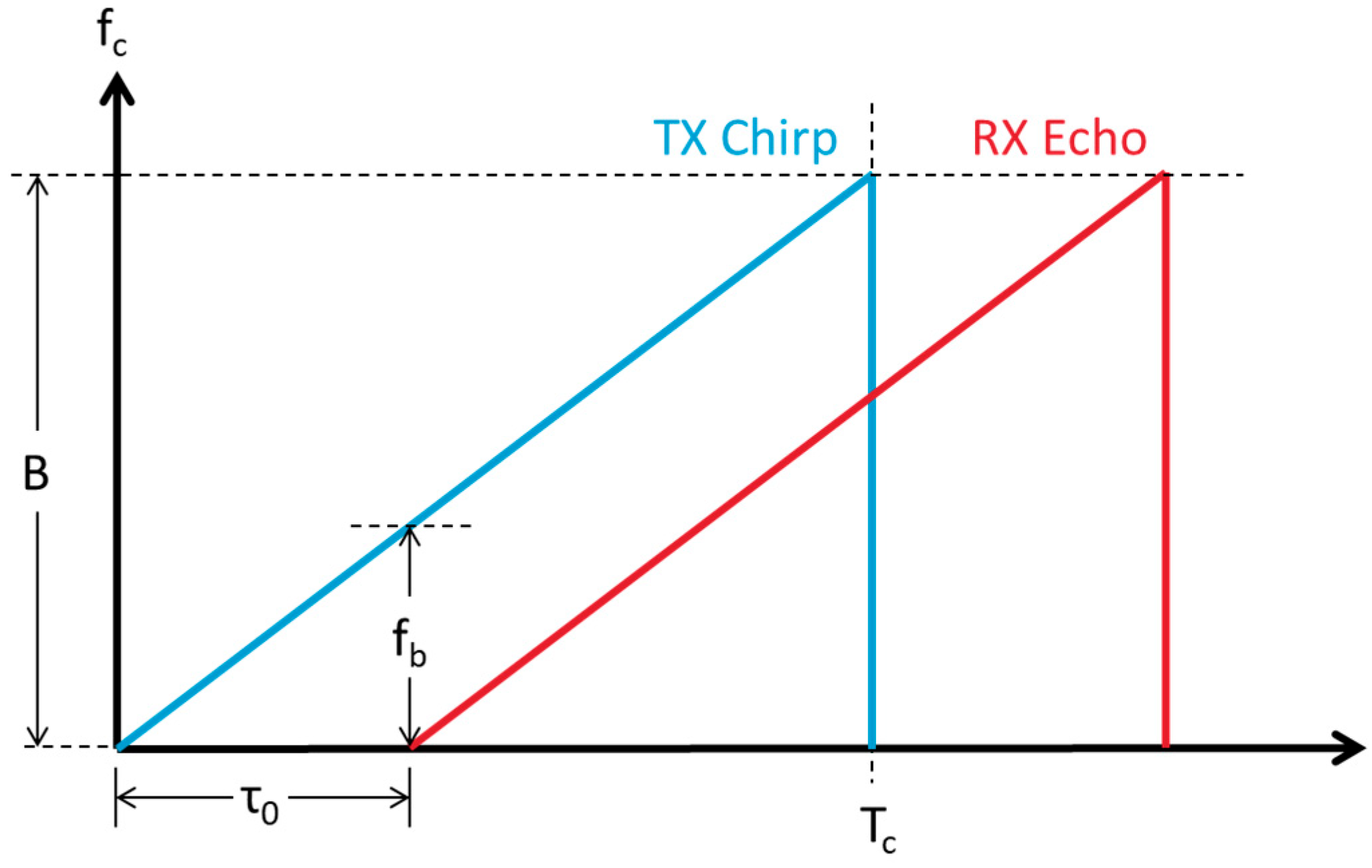
FMCW radar essentially transmits frequency-modulated continuous wave signals toward a target at a distance d
0, and the returning echo is a delayed version of the transmitted signal, with the delay denoted by τ
0. In an FMCW system designed with T
c and B as parameters—where T
c is the chirp duration, B is the chirp sweep bandwidth, and c is the speed of light—the range is determined by the beat frequency
fb, which represents the difference between the transmitted waveform and the echo as described in
Figure 2. The range d
0 between the radar and the target can be expressed by Equation (2). In this study, we focus on a specific
fb, meaning that a specific d
0 is fixed.
If the target undergoes a very small displacement while
fb remains the same between two chirps, the echo delay Δ
τ of the second echo is minimal, and the change in
fb is less than the system’s resolution. This scenario is illustrated in
Figure 3.
The phase of the beat signal from the first chirp and its echo can be described by Equation (3), while the phase of the beat signal for the second chirp is described by Equation (4). The difference between these two phases can be calculated using Equation (5).
The small displacement
d that occurs between the first and second chirp results in a delay Δ
τ, as expressed in Equation (6). The carrier frequency
fc is defined in Equation (7). Consequently, the phase difference Δ
ϕ due to the small displacement is given by Equation (8), and d can be derived from Equation (9).
According to Equation (9), a displacement causes a phase shift in the beat signal, with the wavelength λ being a fixed system parameter. For instance, if d is very small, on the order of 1 µm, and λ is 3.8 mm (i.e., 79 GHz), then Δϕ would be 0.19 degrees. This implies that the sensor system must have the accuracy to detect such a small phase shift (Δϕ). Therefore, this study will examine the accuracy and precision of phase measurements through experimental approaches.
The phase accuracy is dependent on the radar MMIC, and it is not dependent on the supported RF frequency. If the same phase shift (e.g., 1 degree) is captured by both a 24 GHz (λ = 12.5 mm) and a 79 GHz (λ = 3.8 mm) radar system, the corresponding displacement in the 24 GHz system would be 3.3 times larger than that in the 79 GHz system, according to Equation (9). Therefore, a higher-frequency system enables more precise measurements under the same phase shift conditions. Based on this principle, this study adopts a millimeter-wave FMCW radar MMIC.
5. Discussion
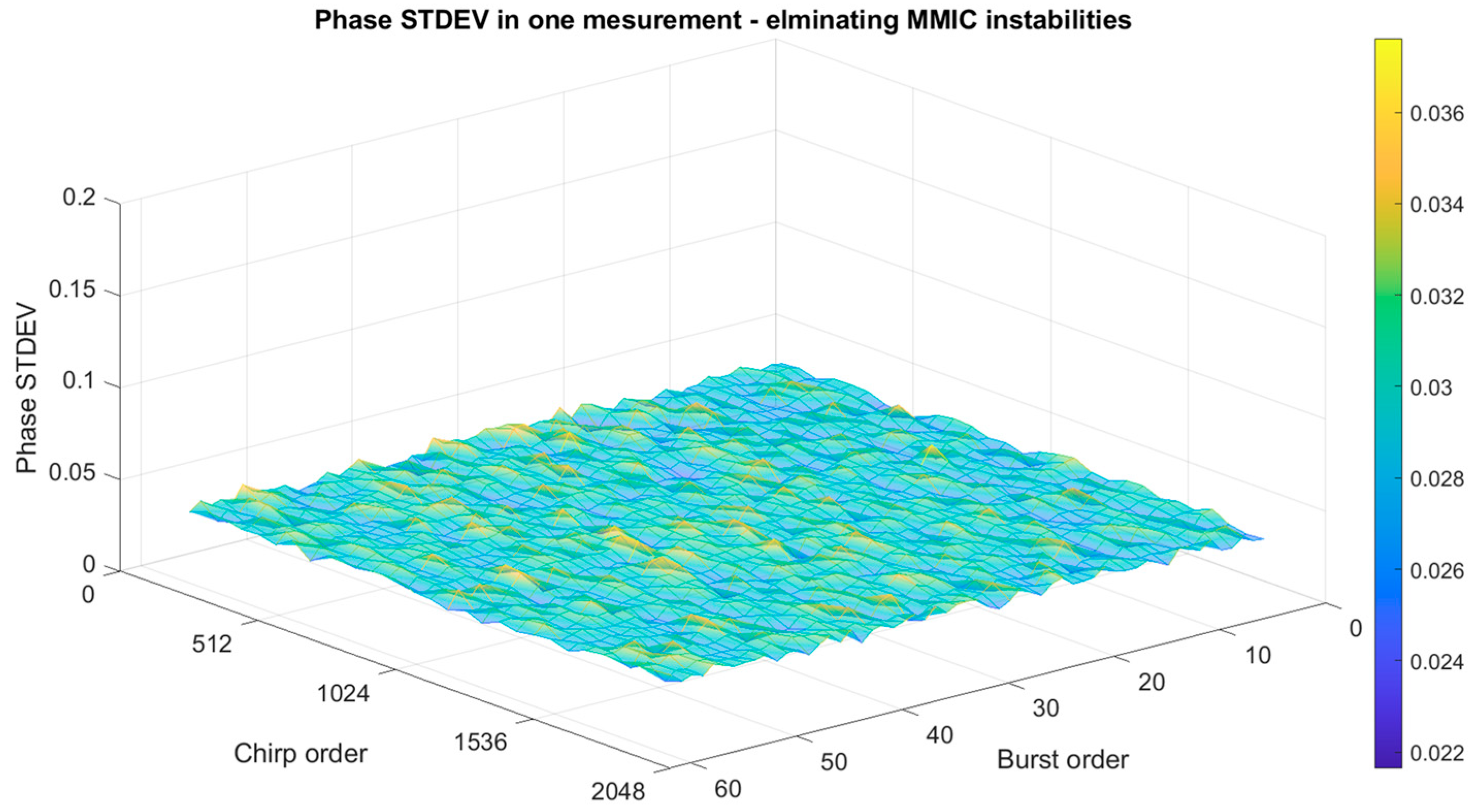
In
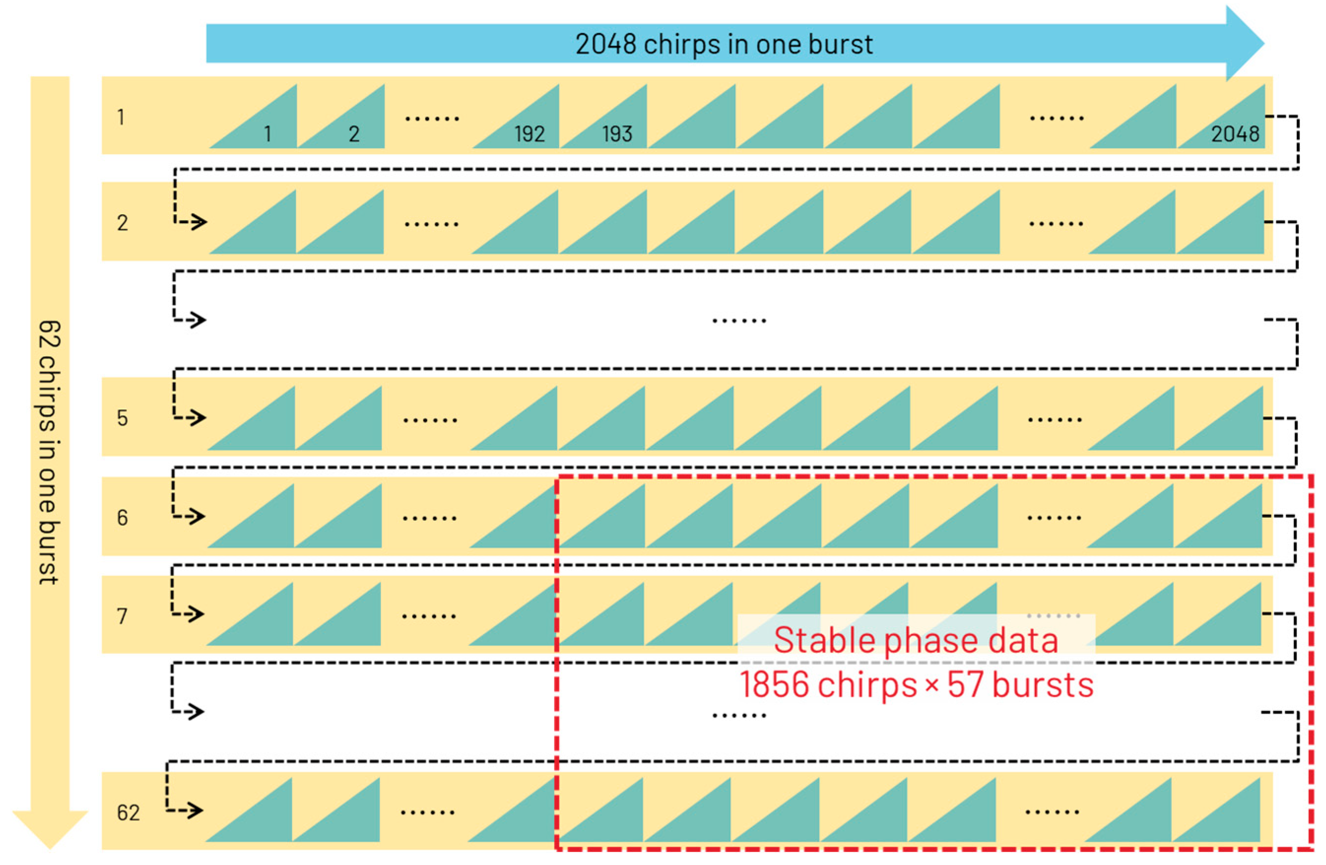
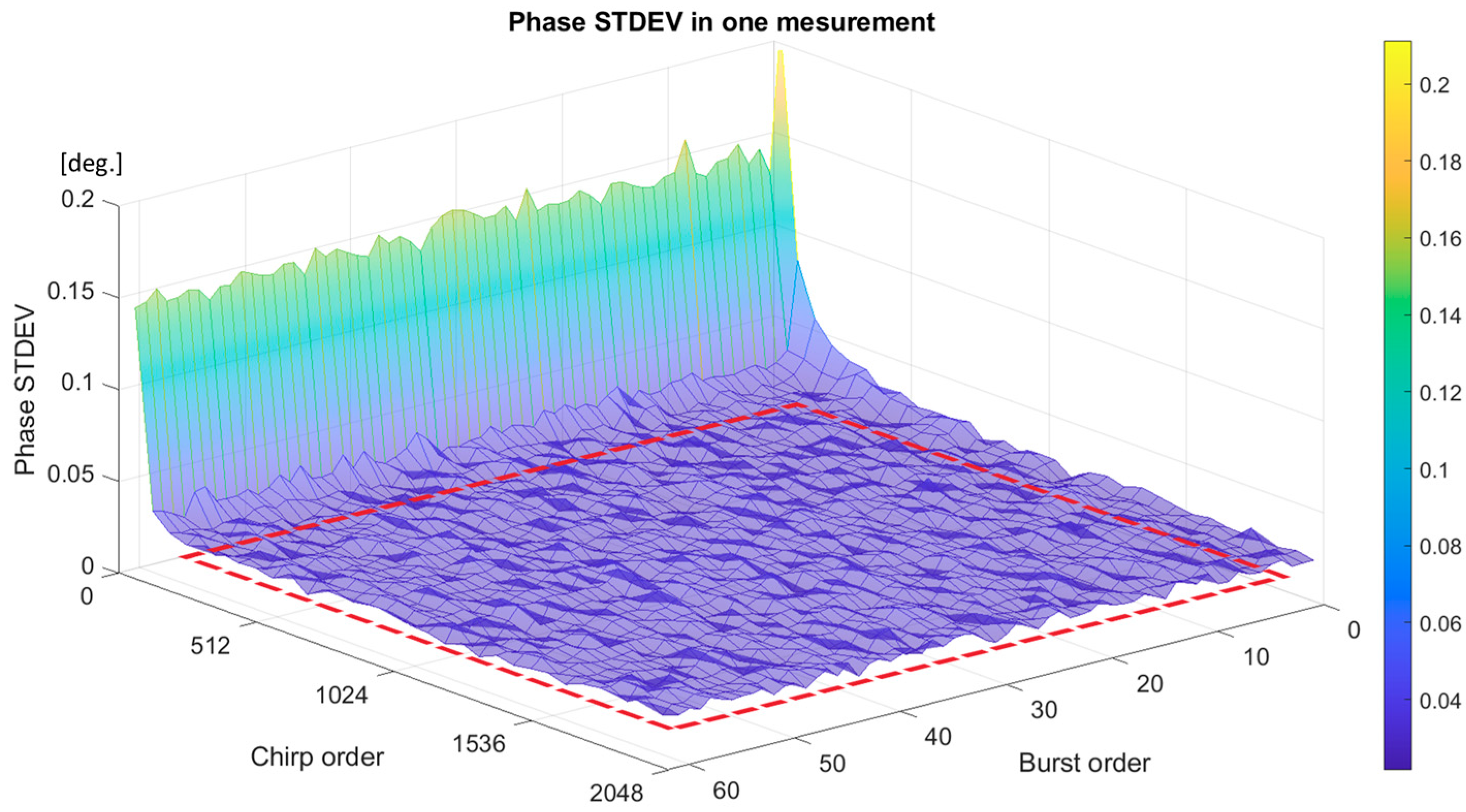
Section 4, there are instability zones in the phase data, and this work eliminated such instability zones as described in
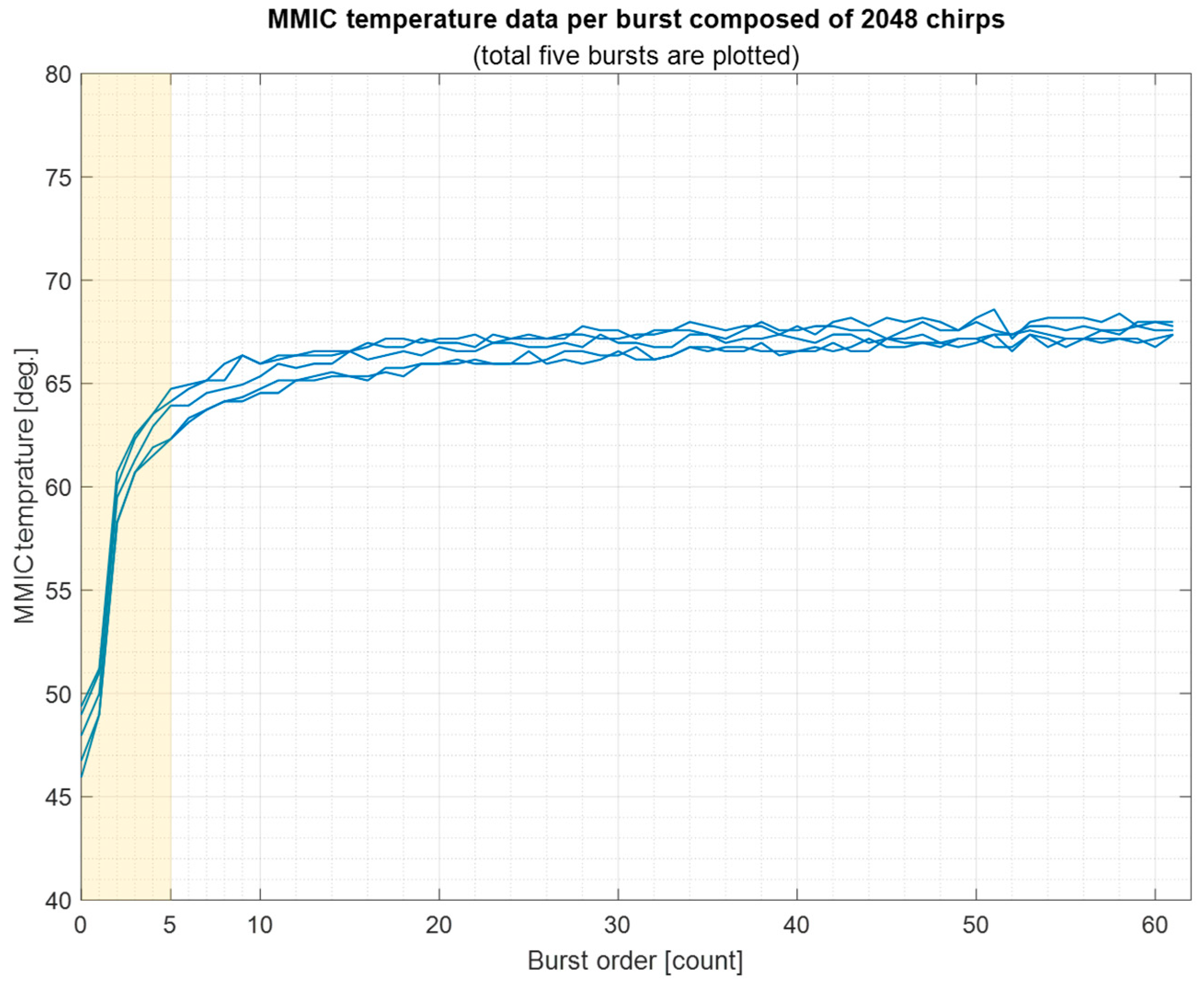
Section 4.1. The instability data appear at the beginning of the waveform in the transmitting process, where the phase is affected by the temperature of the MMIC.
Figure 14 shows MMIC temperature data in the measurement experiment of the loopback waveguide in
Section 3.2, where five measurement trials are plotted. The temperature changes to become higher at the beginning of the first five bursts, as highlighted. Thus, MMIC temperature is sensitive when handling very small phase data.
As mentioned in
Section 4, two error components were observed through the two measurement experiments:
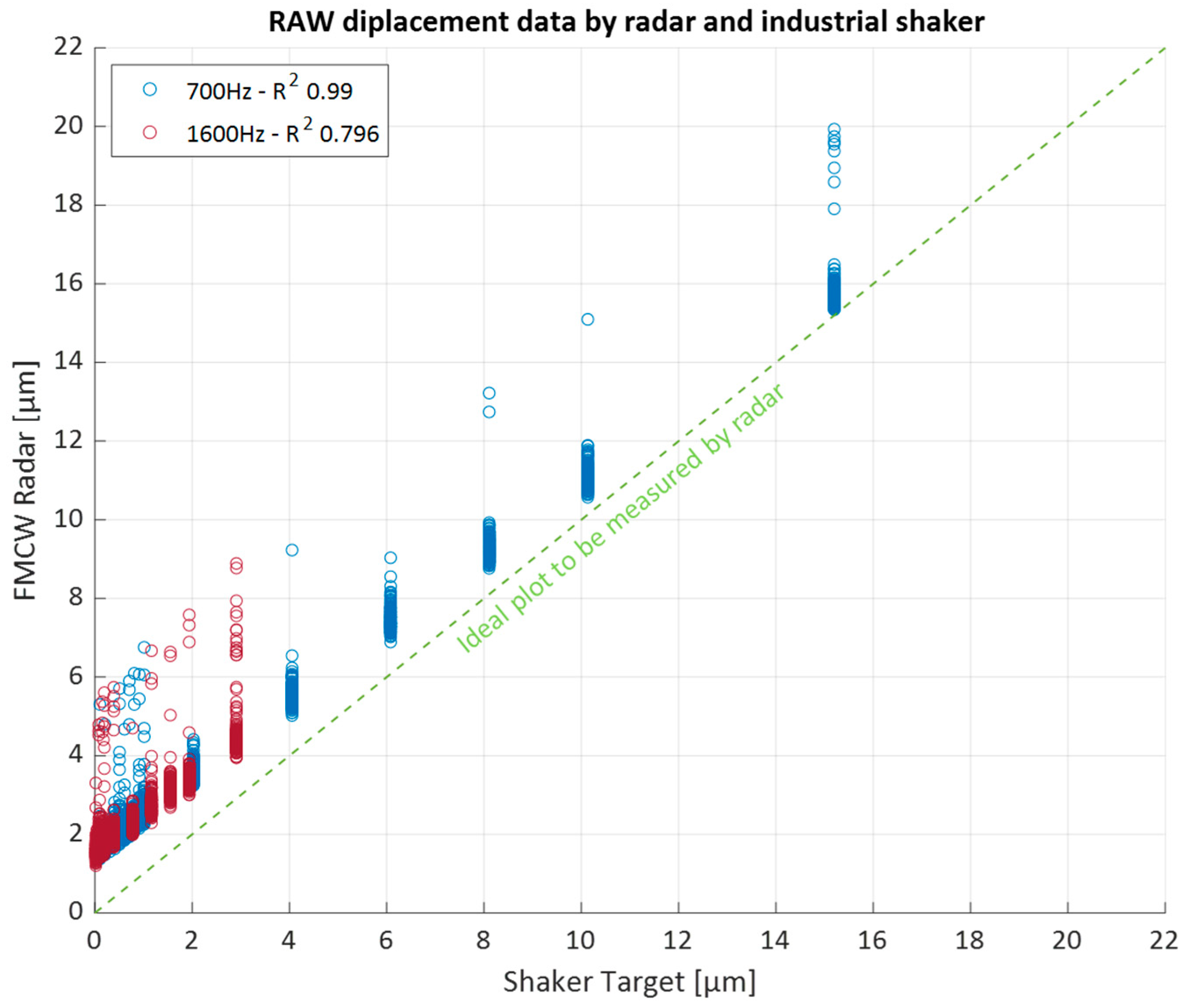
Looking at stability data, the data exhibit strong linearity across the entire measurement range, as shown in
Figure 13, and can be calibrated using appropriate signal processing techniques. For instance,
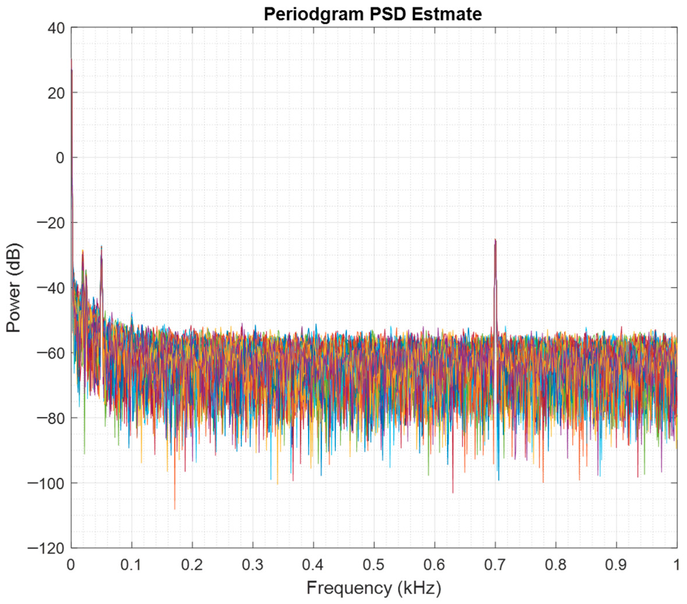
Figure 15 presents a periodogram that estimates the spectral density of the measured phase during a shaker vibration case at 700 Hz with a displacement of 1.013 μm. This reveals unexpected signals at lower frequencies, despite the shaker vibrating at a consistent frequency of 700 Hz.
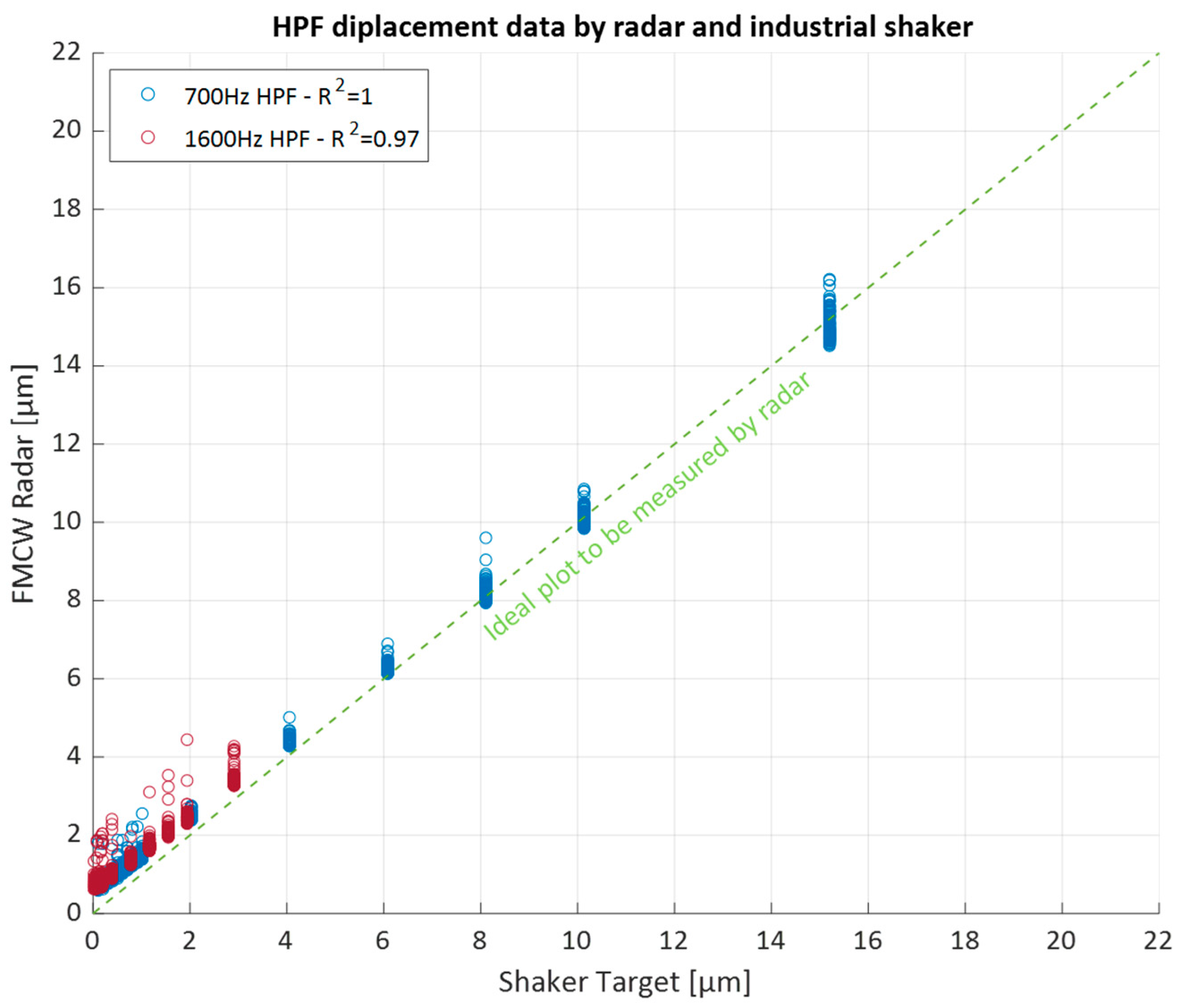
To address this issue, a high-pass filter (HPF) was applied to the sensor data.
Figure 16 displays the results obtained after the application of an HPF with a cutoff frequency of 500 Hz. The application of the HPF reduced the offset, aligning the data more closely with the ideal line. This also improved the R
2 value from 0.99 to 1.00 for the 700 Hz vibration case and from 0.80 to 0.97 for the 1600 Hz vibration case, as summarized in
Table 8. This improvement suggests that the offset is likely caused by low-frequency noise.
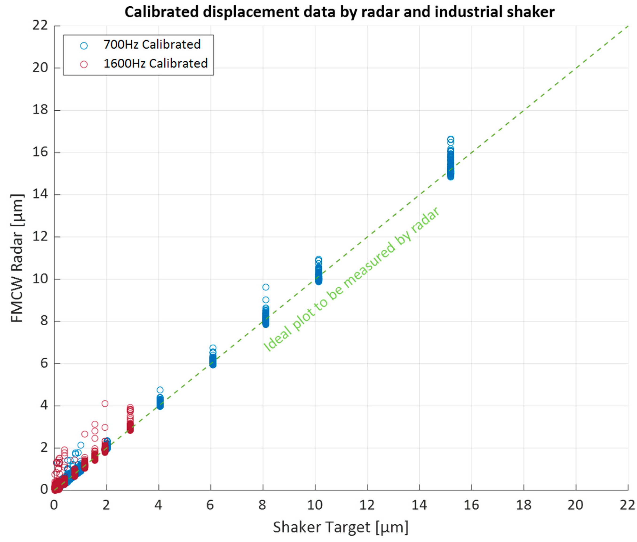
Furthermore, the linear regression model provides coefficients with Equation (9) describing the 700 Hz scenario and Equation (10) describing the 1600 Hz scenario, where
dsht_prt and
dlng_prt are calibrated sensor data, and ds is the raw data measured by the radar sensor. These equations can be used for sensor calibration.
Figure 17 presents the calibrated sensor data using the regression coefficients, demonstrating a close fit to the ideal displacement produced by the shaker. Although calibration was successfully achieved, the cause of the gradient error remains unclear. Future work should address this issue through additional test measurements across a wider range of accelerations and vibration frequencies and various types of shaker machines.
6. Conclusions
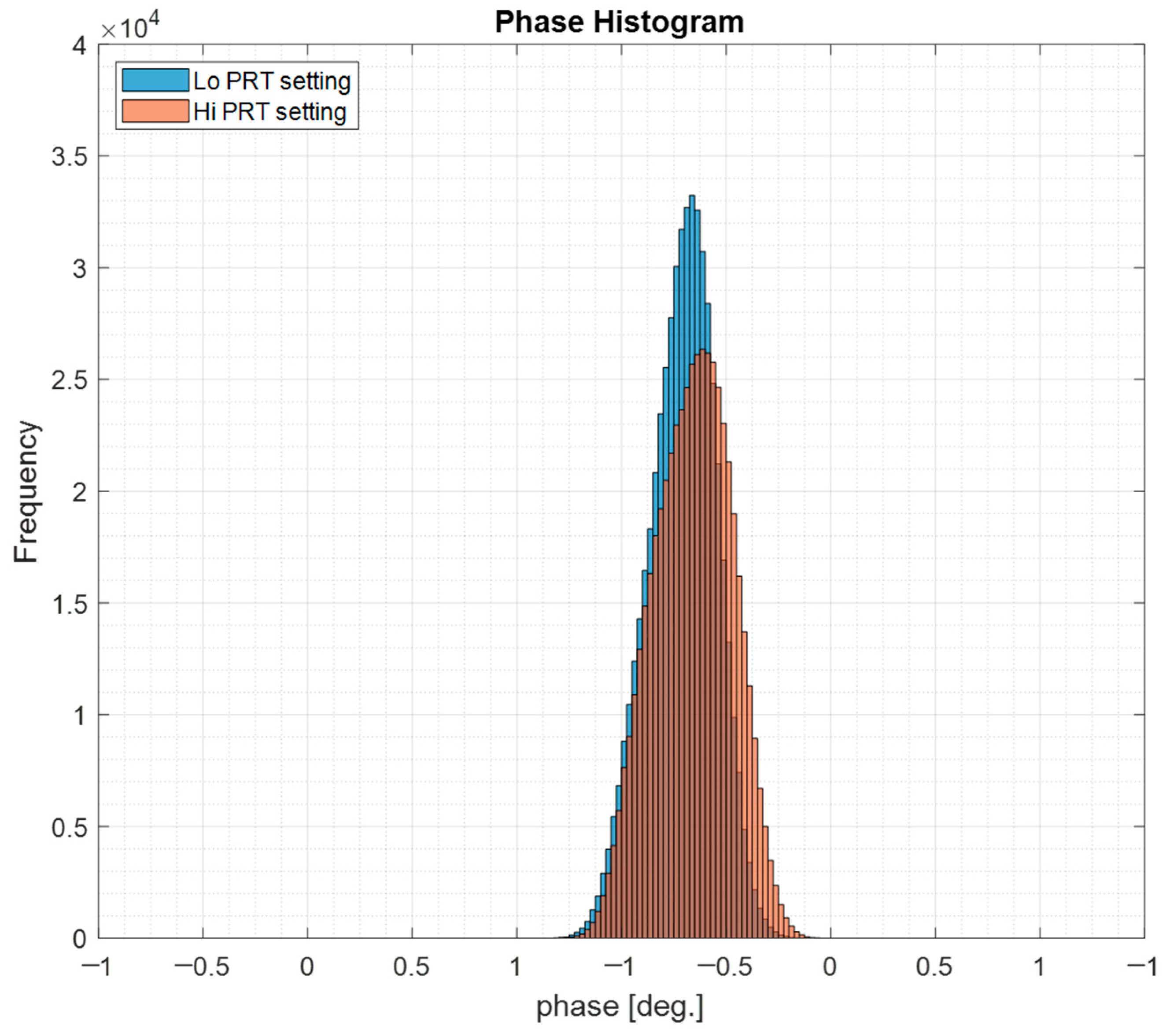
In this study, a millimeter-wave FMCW radar sensor system was developed for small displacement sensing, and its phase accuracy and precision were experimentally evaluated using two test scenarios. The sensor demonstrated a phase accuracy shift of +0.137 degrees with a standard deviation of ±0.222 degrees. The maximum observed shift was +0.359 degrees, corresponding to a displacement offset of +1.907 μm. This offset falls within a 3-sigma condition, confirming the sensor’s accuracy. Similarly, the 3-sigma deviation of ±0.222 degrees corresponds to a displacement precision of ±1.180 μm.
The industrial shaker test verified the sensor’s capability to measure displacements ranging from 15.198 μm to as small as 0.019 μm with good linearity, as confirmed by regression analysis. Applying a high-pass filter and calibration using regression coefficients effectively aligned the measured displacement with the reference values. After calibration, the sensor precision (±1.180 μm) equaled its accuracy.
Future work will address identifying the root causes of the observed errors to further enhance reliability. Additional measurements under varied vibration conditions, including different frequencies, accelerations, and shaker types, will be conducted to better understand the influence of radar MMIC characteristics and the mechanical properties of the shaker machine on sensor performance.
