1. Introduction
Lower-limb length discrepancy (LLD) is defined as a discrepancy between the lengths of the two lower limbs, occurring when the natural symmetry of the body is affected. LLD, when exceeding the limits accepted by clinicians, can affect locomotion, balance, posture foot pathologies, and low back pain [
1,
2]. LLD can be categorized as either structural (anatomical), where limb inequality is caused by bone structure, or functional (apparent), where biomechanical changes such as knee or foot deformities (varus or valgus) and spinal abnormalities (especially functional scoliosis in children [
1]) are present. LLD leads to a shift in the normal position of the center of mass (CoM), thereby disrupting the proper functioning of the human body, including changes in gait kinematics [
2,
3,
4].
There are several methods and devices available for measuring limb length discrepancy (LLD). Traditional devices, typically operated by medical specialists, offer limited accuracy; these include methods such as direct limb measurement and bubble level devices. Modern methods, on the other hand, rely on advanced technologies such as imaging, ultrasound, and large-scale devices designed for precise center-of-mass determination. However, these advanced systems are often inaccessible to most patients due to their size, cost, and the specialized environments in which they are typically housed [
4,
5,
6,
7,
8,
9,
10].
Accurate measurement of LLD is crucial in the study of both functional and anatomical LLD. Subjects are often unaware of an LLD smaller than 20 mm, and a discrepancy of up to 20 mm can typically be tolerated [
2,
11]. Additionally, the literature indicates that an LLD greater than 20 mm causes pathological changes in gait and induces fatigue in the quadriceps muscle of the longer limb [
12]. It has been reported that subjects can perceive a limb length discrepancy greater than 20 mm [
13]. Furthermore, in cases of structural LLD, a greater vertical ground reaction force is observed on the shorter limb compared to the longer limb. For example, when LLD is 3.5 cm, the load on the shorter limb reaches 64% of the subject’s body mass [
3,
14,
15]. Both categories of LLD (anatomical and functional) are associated with hip or knee osteoarthritis and other mechanical pathologies resulting from improper distribution of load across the limbs [
16].
Changes in spinal kinematics were studied in 20 subjects with unilateral transtibial amputation (prosthesis wearers for at least 1 year) by simulating LLD through the placement of 30 mm wooden blocks under the foot. Limb inequality resulted in lateral pelvic tilt, which in turn caused lateral bending of the subjects’ spines. The changes induced by a shorter prosthetic limb appeared to be more substantial than those induced by a longer prosthetic limb [
11].
It is well known that prosthetic users must make two visits per year (depending on age and growth stage) to a specialist for monitoring the alignment of the spine, pelvic girdle, and limb length discrepancy. As the child grows, adjustments to the prosthesis parameters or regular replacement of the prosthesis are necessary to ensure proper fit that keeps pace with the patient’s growth. Typically, the conventional prosthetic device is replaced once a year [
17].
Conventional prostheses designed for patients in the growth period require length adjustments as long as the prosthetic structure allows (at which point replacement is necessary). Their replacement occurs at least once a year, and specialist consultations are typically conducted about twice a year [
17]. Some prostheses allow for adjustment by removing the artificial foot and inserting elements, such as wooden blocks, between the foot and the prosthetic rod. This process compensates for the limb length discrepancy until it matches the contralateral foot. Adjustable rods with metal inserts, which are fixed at a specific length, are also used to achieve the same effect [
18].
The Ring concept, which features passive adjustment for length modification, is well known. This prosthetic concept was developed by designer S. Jeremic and is specifically designed for children with unilateral transtibial amputations in developing countries. To modify the length of the prosthesis during the child’s development, additional modular rings are added to increase length as LLD emerges due to growth [
19]. Similarly, the FIT concept proposed by designer O. Benderman promotes the idea of length adjustment through a central modular rod, allowing the user to extend or shorten the prosthesis as needed. This cost-effective concept is intended for manual adjustment to ensure a customized fit (over several years) for the residual limbs of children with amputations in developing countries [
20,
21].
Additionally, a CAD version of a module consisting of two interlocking tubes with different diameters is available, which can be secured at the desired length using an elastic bushing [
22].
As an attempt to address the issue of adjusting the length of lower-limb prostheses for proper fitting over several years as the patient grows, prosthetic assembly was developed. This assembly consists of a prosthetic foot attached to an adjustable rod secured with a bushing and screw [
23]. The system also allows for the length adjustment of the foot by shifting a component that simulates the forefoot and attaches to the midfoot. The prosthetic rod, which is made entirely of mechanical components without any electronic systems, can be lengthened or shortened manually based on the growing child’s needs. This adjustment is intended to be performed manually (without any measurement system), without the need for visits to a specialist or the involvement of expert advice [
23,
24,
25].
The needs of patients in developing countries and the high cost of prosthetic devices make it impossible to frequently change the prosthesis in accordance with the development of a growing amputee child. Therefore, for a 9-year-old female patient with a transtibial amputation, an adjustable aluminum rod was developed (with an extension of up to 50 mm, with a 1 mm pitch), secured with a counter nut. The rod, suitable for use in modular prostheses, was placed between the classic prosthetic foot and the prosthetic socket [
25]. A similar design for an adjustable prosthetic rod for the lower limb, with counter nut fixation, was designed to facilitate the adjustment of prostheses for disadvantaged children [
26]. It was reported that the prosthesis was changed for 15 children (out of 28 monitored) on two occasions within a 6-month period, once after 3 months for 5 patients, while no adjustments were reported for the remaining patients or for those not monitored. Additionally, another prosthetic limb with adjustable length contains a screw-and-nut mechanism that allows for elongation when the screw is manually rotated (by the prosthetist or user), with rotational motion being converted into linear motion [
27].
Additionally, the design of a passive lower-limb prosthesis has been reported, featuring incremental length adjustment through the manual operation of a system consisting of three interlocking rods. This system is functionally similar to other prostheses that allow for such adjustments. The rod would enable the user to adjust the length while using the same prosthesis over a period of several years (suitable for users up to 10 years old) [
28].
All current prosthetic length adjustment devices are manually operated, lacking automated or autonomous components, which may introduce usage errors and require specific training for precise adjustments. Currently, the specialized literature and medical practice do not include an adaptive prosthesis model capable of detecting limb length discrepancy (LLD), eliminating these limitations, and simplifying the alignment process for the prosthetic patient.
In this context, our multidisciplinary team, comprising bioengineers, mechanical engineers, and electronics engineers, developed an innovative prosthetic device—an auto-adaptable transtibial prosthesis—to support unilateral transtibial amputee patients during their growth period. The following steps were taken in the development process: firstly, the CAD design of the prosthesis was executed; secondly, 3D printing was utilized for fabrication; thirdly, the device was implemented on an anatomical mannequin; and finally, a detection and compensation system for limb length discrepancies was developed. The results demonstrate the concept, design, and early prototyping of the first self-adaptable transtibial prosthesis.
3. Results
3.1. Materials and Devices Used in the Implementation of Test Stands
The materials used and the electronic components integrated into the functional prototypes that are pivotal to the detection and compensation system of lower-limb length discrepancy (LLD) are indicated and briefly described. This description encompasses the primary technical specifications of interest in this work, performance characteristics, and the rationale behind the selection of these elements. These materials and electronic components were integrated into operational prototypes, demonstrating their feasibility in real-world scenarios, thereby ensuring both the required clinical functionality and optimal electrical and mechanical performance for the automatic adjustment of prosthetic length.
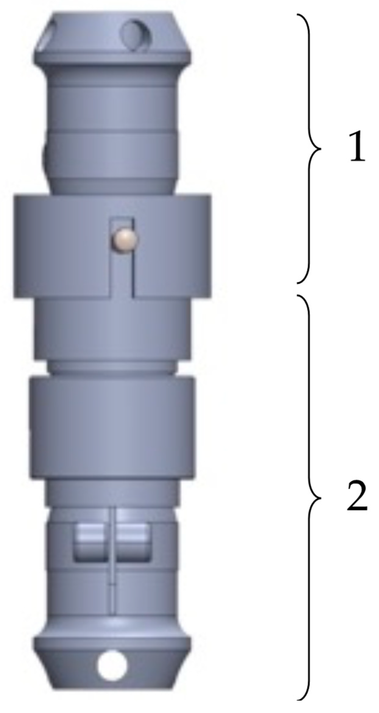
3.1.1. Prototyping of the Expandable Prosthetic Module
In
Figure 3, the final construction variant of the EPM for lower-limb prostheses is illustrated. It consists of a mobile prosthetic assembly (1) and a fixed prosthetic assembly (2), positioned between a socket for residual limb support and the artificial ankle joint, which can be either active or passive.
It was observed that the mobile prosthetic assembly (1) contains a pyramidal adapter with a screw-based fixation system, allowing it to connect with the standardized pyramidal systems attached to commercial prostheses. The adapter partially houses a flange that rests on it, into which a casing with a shoulder is screwed. This casing supports another casing, which is also fixed by screwing. The fixed prosthetic assembly (2) consists of a flange into which the casing is inserted and fixed into a pyramidal adapter identical to the one in the mobile assembly. This adapter attaches the prosthetic socket or the osteointegrated implant at the patient’s residual limb level using standardized fixation elements. The fixed assembly also contains a DC motor, which operates a screw–nut mechanism that converts rotational motion into linear motion.
We used a 12 V CHR-GM25-370 DC motor to drive the EPM, which has the technical specifications listed in
Table 1.
In this iteration of the prototype, the EPM was modified to enhance its robustness. The prototype was found to have a weight of 680 g. It is hypothesized that, for a prototype intended for clinical testing, the weight can be significantly reduced through the optimization and refinement of components.
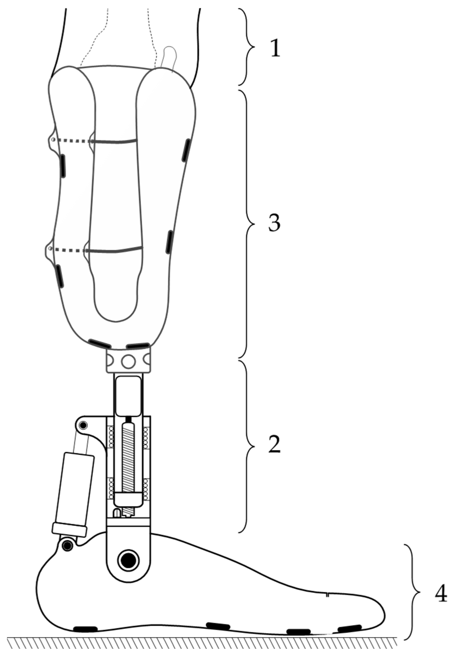
In order to simulate the most realistic conditions for testing the EPM, we selected an anatomically shaped mannequin on which intervention was performed by sectioning the left lower leg. This simulates laboratory conditions similar to those of a patient with a transtibial amputation (
Figure 4).
In accordance with the standardized dimensions in the field of prosthetics, two pyramid-shaped elements were made and attached to the extremities of the extensible prosthetic module (EPM). These components enabled the integration of the EPM into the mannequin, which was positioned in a seated position on a rigid chair, with the shins oriented approximately perpendicular to the base plate that supported the feet. Both feet were fixed using fastening devices, ensuring stable connection to the base plate and precise alignment of the forming elements.
The EPM components are fabricated from robust materials, with a weight capacity of approximately 70 daN. It is important to note that the prosthesis does not correct LLD under the weight of the entire body or the affected side of the body. Adjustment of the prosthetic length takes place when the subject is in a seated position, so the load on the EPM is minimal. In the unlikely event of additional motor power being required, the EPM’s modular design allows for the replacement of the motor with a more powerful one.
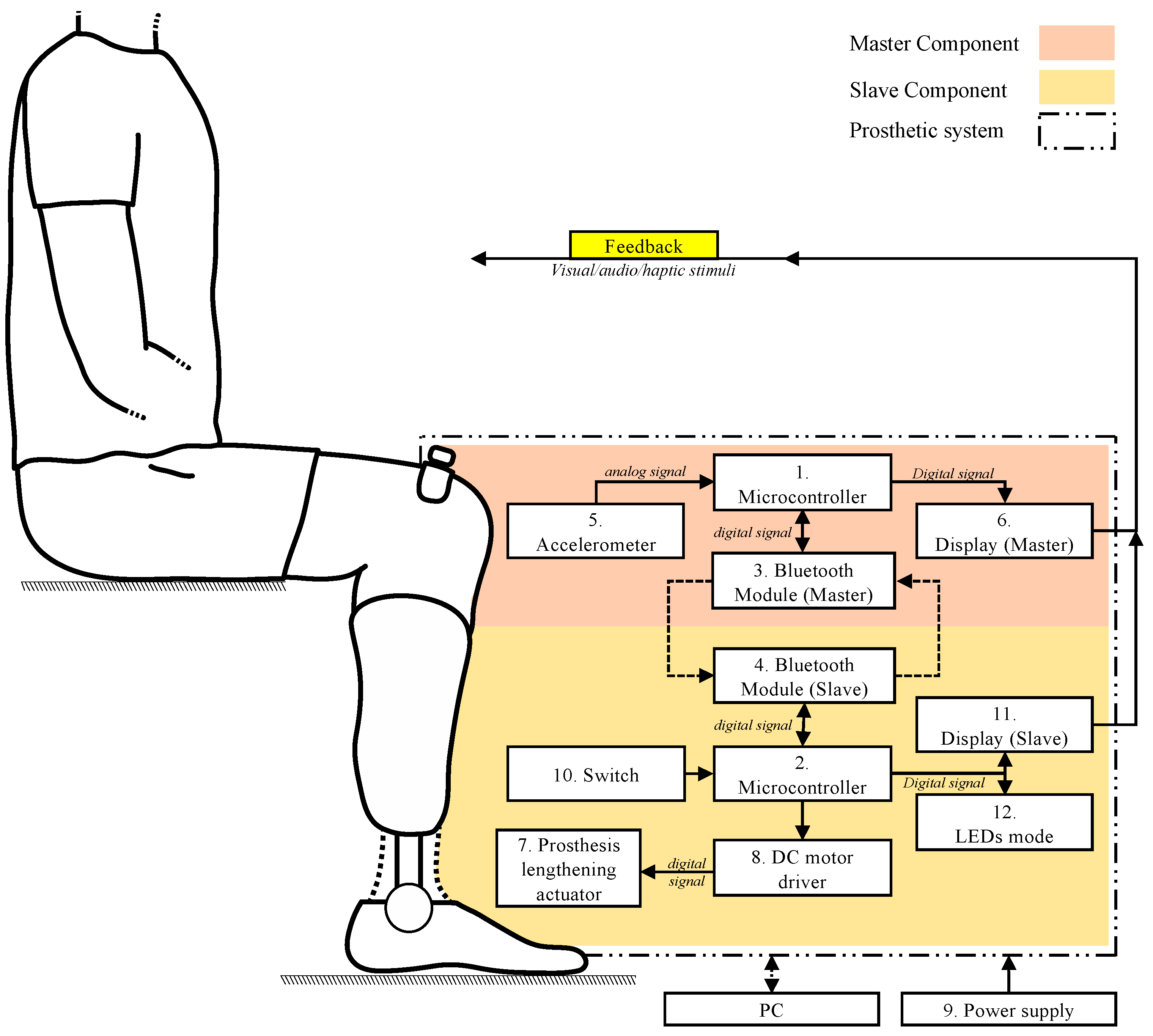
3.1.2. Architecture of the Master Component
The Master component is responsible for determining the limb length discrepancy (LLD), a process that is carried out using an I2C MPU 6500 accelerometer (InvenSense Inc., San jose, USA). This sensor is able to monitor the position of the affected limb, thus contributing to the rapid detection of the length discrepancy required for an efficient correction. The main technical characteristics of the accelerometer are presented in
Table 2.
The
Y-axis of the I2C MPU 6500 accelerometer was utilized for the detection of LLD, a decision that was informed by its alignment with the operational position of the Master component prototype mounted on the prosthetic body. The
Y-axis signifies the direction in which variations in position that are pertinent to LLD detection are documented. The data collected by the accelerometer are then transmitted to the ESP 32 development board (see
Table 3 for a detailed list of the parameters), which processes the information in real time to generate the commands necessary for compensation. The system’s functionality is predicated on the input variable LLD, as determined by the inclination detected by the prosthesis sensor. The accelerometer mounted on the Master measures this inclination, while specialist software interprets it to restore the user’s body symmetry. The sensor detects gravitational acceleration on the
Y-axis, and the AccY variable, displayed on the screen, represents a scaled version of this acceleration. Consequently, the system undertakes an analysis of the inclination angle of the pivoting bar and determines LLD.
The data characterizing the position of the lower limbs of the prosthetic individual, as well as the connection status between the Master and Slave components, are monitored and displayed in real time on an OLED display. This display features technical characteristics suitable for biomedical applications, allowing for the rapid visualization of the information. The main characteristics of this display, including the display resolution and compatibility with embedded systems, are presented in summary in
Table 4.
The OLED display has been developed to provide a user-friendly interface, facilitating the real-time evaluation and adjustment of critical parameters, such as the position of the prosthetic limb and the stability of the wireless connection. This solution contributes to the efficiency and accuracy of LLD correction, offering immediate and detailed visual feedback, which is essential for monitoring LLD.
3.1.3. Implementation Details in the Master Component
As previously outlined, the electronic components described previously were integrated into an experimental physical prototype, as illustrated in
Figure 5. This prototype, designed for the detection of lower-limb length discrepancy (LLD), allows for the real-time display of the collected and analyzed data. The power supply for the prototype is provided via the USB connection to a 5 V source, ensuring stability and continuous operation. Although the system is currently powered through a physical electrical connection, the prototype was designed to integrate an internal battery, which would allow for greater mobility and independence in its use. This innovative approach was adopted to ensure system stability during experimental testing on the stand, thus minimizing potential interruptions caused by voltage fluctuations or the loss of connection when using an uncalibrated battery that does not currently meet the operational requirements of the Master component.
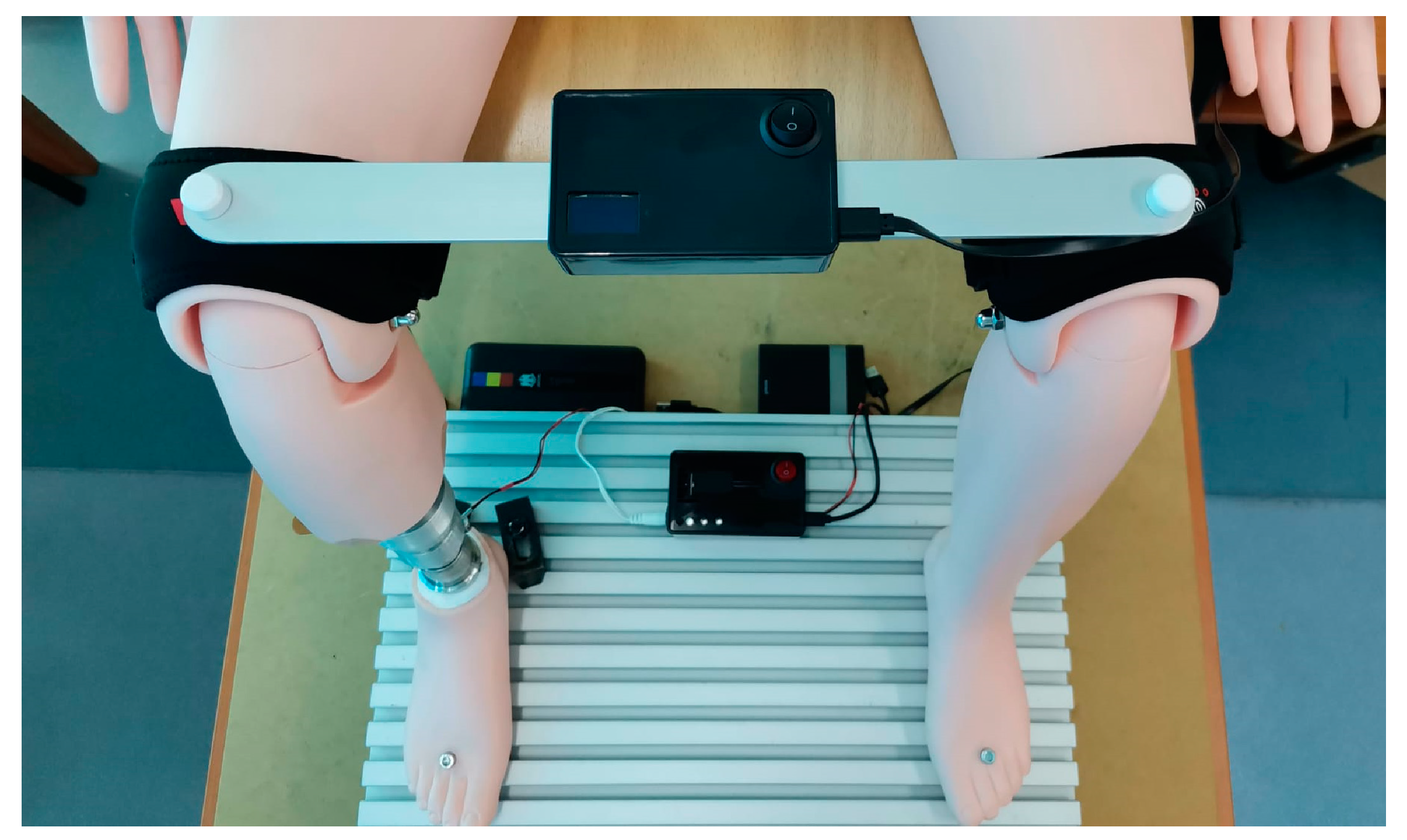
The physical prototype was mounted on a rigid plate positioned at the midpoint of its length, constructed from an aluminum alloy to ensure minimal weight. As illustrated in
Figure 6, the extremities of the rigid bar were positioned on the suprapatellar regions of the anatomical mannequin, which was situated in a seated position. This configuration simulated the clinical situation of a patient with a prosthetic lower limb.
Two medical orthoses were integrated at the ends of the bar, surrounding the distal region of the thigh, with the intention of increasing stability during testing and minimizing errors, without the intention of their use on a real patient.
It is important to mention that the rigid bar is securely fixed to the suprapatellar regions of the mannequin through fastening elements, allowing a solid and non-elastic connection between the ends of the bar and the mannequin. During the experimental tests, the prototype enables the evaluation of the LLD detection and compensation system’s functionality, with all components integrated and assembled to ensure an assessment as close as possible to real clinical scenarios.
3.1.4. Architecture of the Slave Component
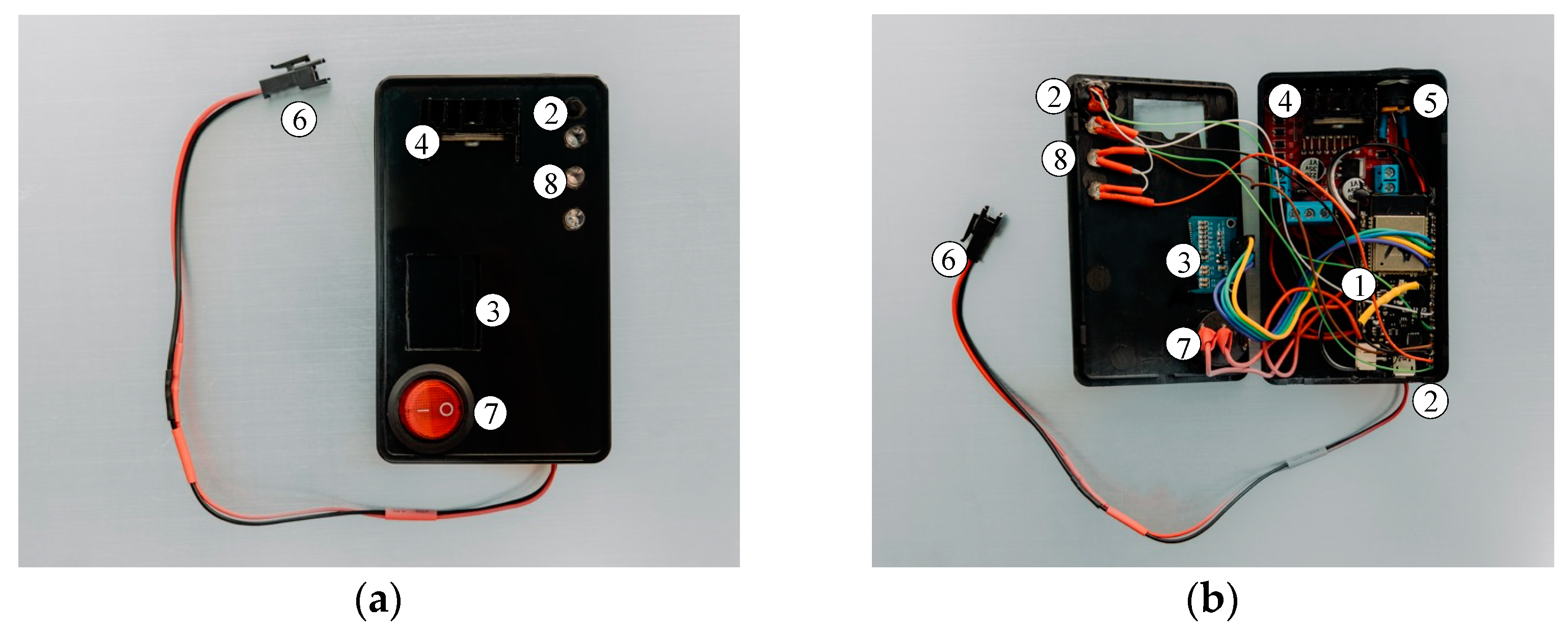
For the practical implementation of the Slave component prototype, several electronic and electrical components were used, which can be seen in
Figure 7.
The Node MCU Lolin 32 development board manages the operation of the prototype, ensures wireless connectivity through the integrated Bluetooth module, and communicates with the Master component, which is equipped with an identical board, thus enabling real-time data exchange.
The development board is powered through a dedicated USB connection with a 5 V power source. The Bluetooth connection between the two components is automatically established when the microcontrollers are powered, thereby enabling low-latency interaction between them. Information regarding the connection status is displayed on an OLED screen, which is identical to the one used in the Master component prototype. Additionally, in a manner analogous to the Master component, the Slave component displays real-time information about the position of the mannequin’s lower limbs.
The Slave component is functionally connected to the electric actuator, which is integrated into the extensible prosthetic module (EPM). The connection is facilitated by an L298N module that uses a double “H” bridge for controlling the actuator’s direction. The module is powered through a dedicated connection with a 12 V supply, and the power can be activated or deactivated via an on/off switch. The main characteristics of the driver are listed in
Table 5.
This electrical configuration allows for precise control of the actuator, ensuring a fast and efficient response to commands received from the main microcontroller (Slave).
3.1.5. Implementation Details in the Slave Component
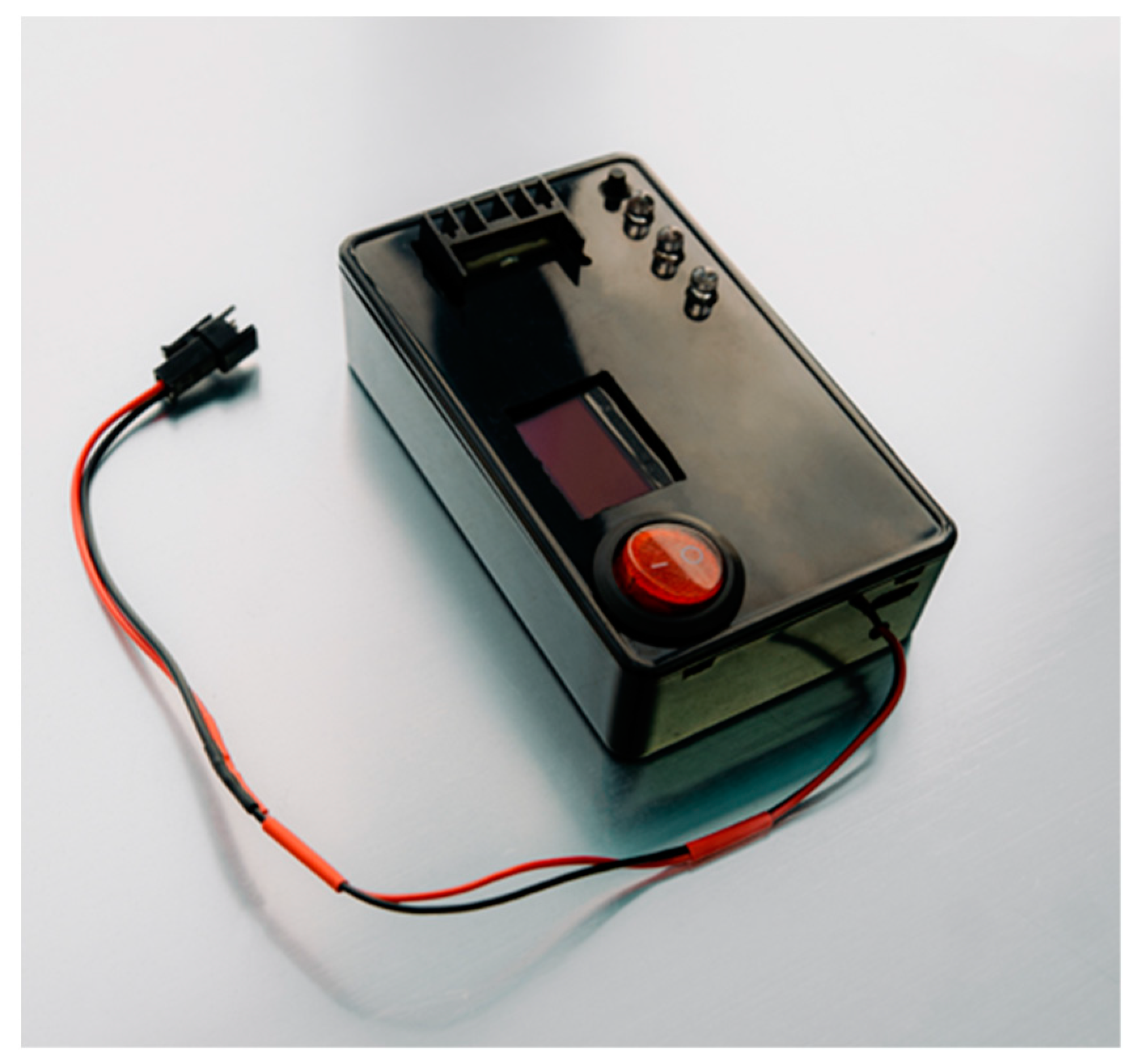
The user receives real-time feedback regarding the actions performed by the Slave microcontroller (Node MCU Lolin 32, Espressif, Shanghai, China). For instance, when the push button is pressed for the first time, the system activates the limb length discrepancy (LLD) correction mode, and an LED module visually indicates this action. Simultaneously, the LEDs inform the user about the action being performed by the MOPE (operational module), providing immediate feedback. Upon the second press of the button, the LLD correction mode is deactivated, and the system returns to a standby state, ready for a new action. Thus, the user can intuitively control and monitor the LLD correction cycle, ensuring precise control over the device.
The final version of the prototype is shown in
Figure 8.
3.2. Simulation of Test Conditions for the Self-Adjusting Transtibial Prosthesis
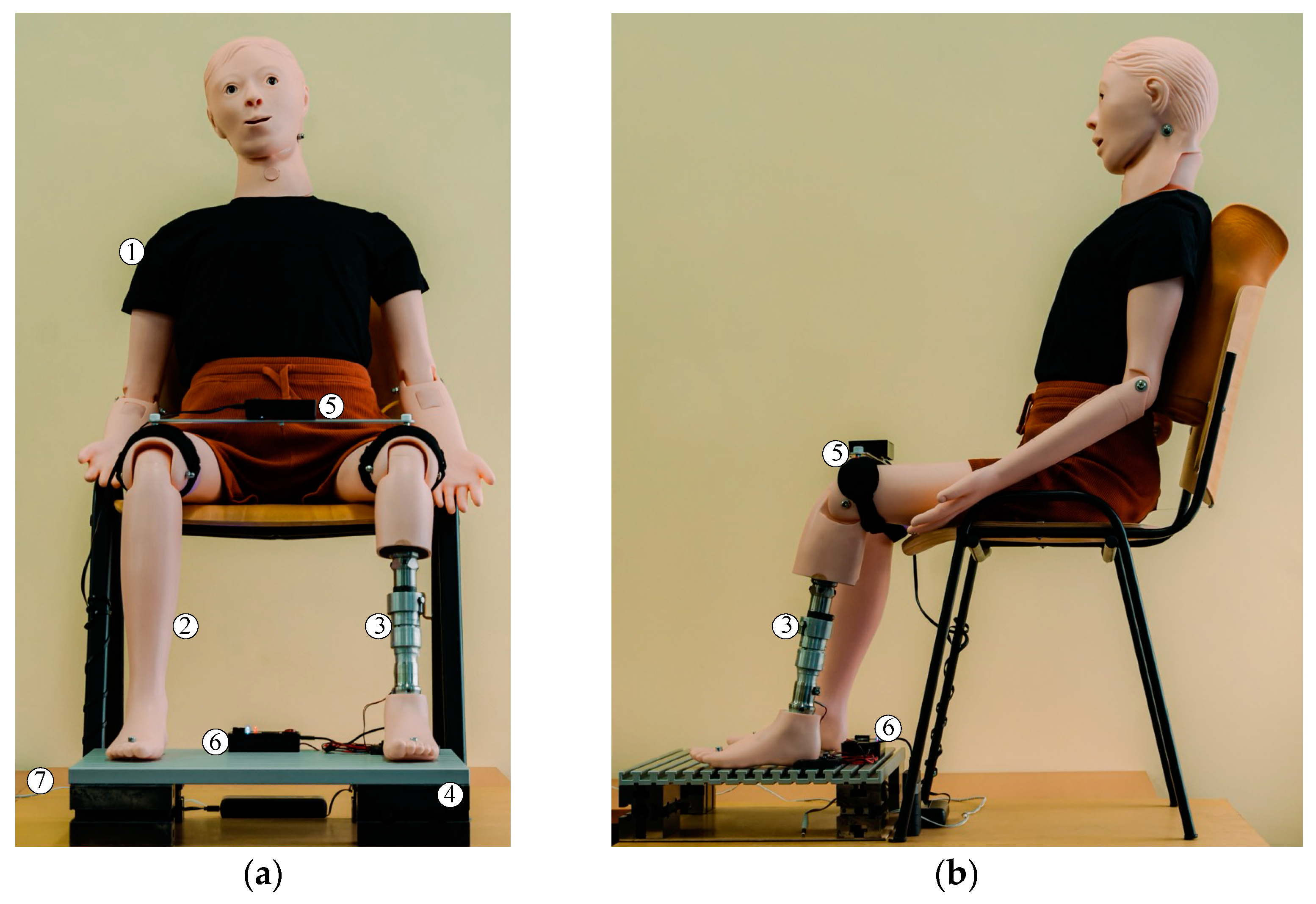
The Master and Slave components developed have the capability to maintain fast wireless connections, enabling the implementation of a distributed control system, with each component handling part of the processing load, reducing complexity and increasing system efficiency. Bidirectional communication between the two components is achieved in real time, allowing the rapid transmission of data from the accelerometer in the Master component (which detects LLD) to the Slave component, which is responsible for the prosthetic adjustment via the EPM.
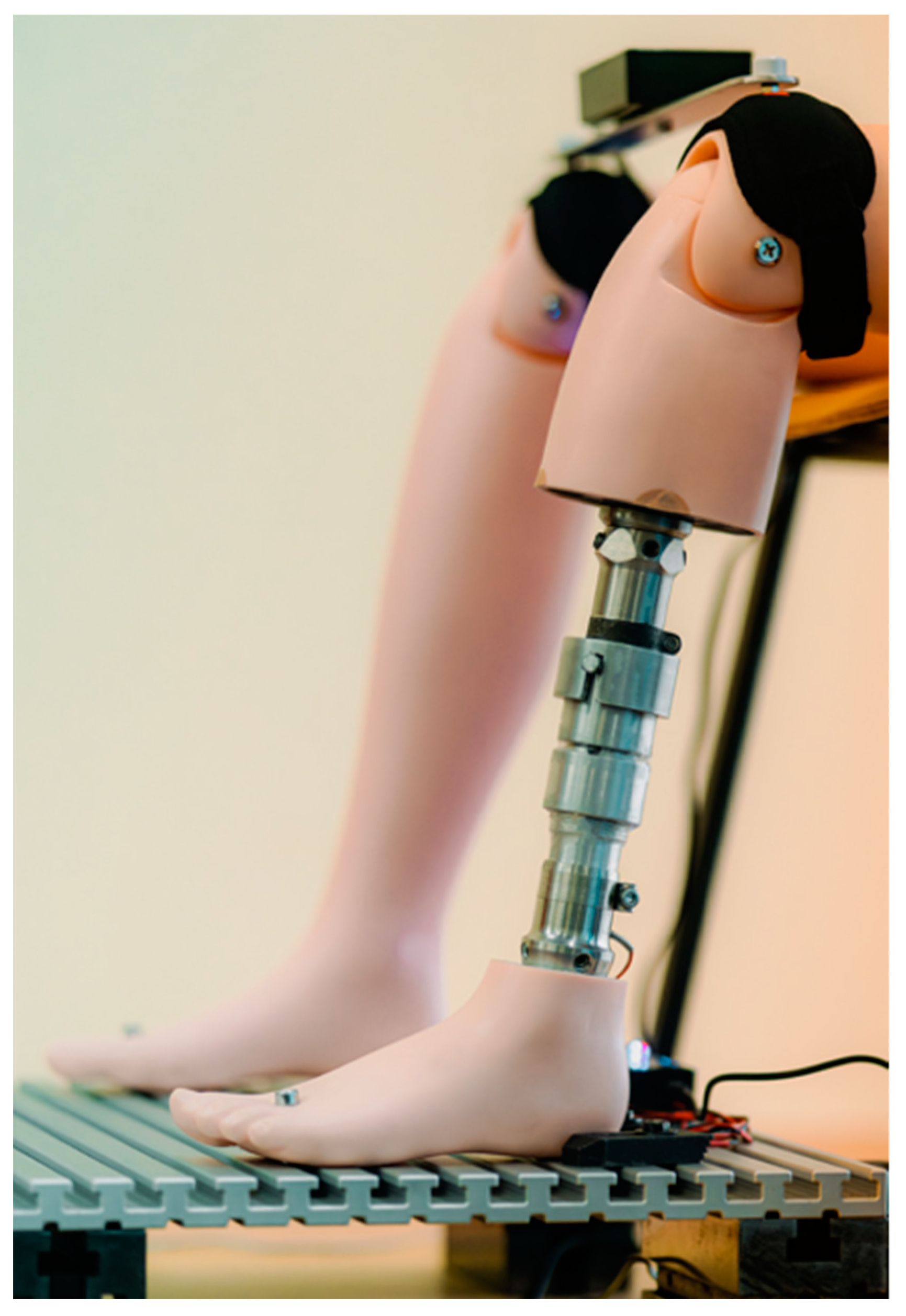
The collaborative operation of the Master and Slave components in this prototype facilitates the detection and correction of limb length discrepancy (LLD) at the experimental setup level depicted in
Figure 9.
The Master component is strategically placed at the suprapatellar regions of the mannequin, ensuring monitoring of the lower-limb length inequality, while the Slave component is positioned on the base plate and connected to the EPM.
The power supply for the self-adjustable prosthesis is provided by an external power source. This is to obviate the necessity for the patient to carry auxiliary electronic components with them at all times. This has a significant effect on the weight of the prosthesis.
The experimental setup in this configuration enables the evaluation of the adaptable transtibial prosthesis, with specific reference to the accuracy with which the Master component detects the simulated limb length discrepancy (LLD) at the level of the mannequin’s right lower limb. Concurrently, the Slave component is responsible for correcting the detected discrepancy in real time by sending an electrical command to the EPM. The precision and efficiency of the detection and correction process are validated using a DIC-type metrological system for high-accuracy measurements.
3.3. Testing the Prosthesis’s Movement
The behavior of the self-adjusting transtibial prosthesis during movement was evaluated using a Digital Image Correlation (DIC) system. The DIC method is a non-contact, non-destructive measurement technique that involves calculating 2D or 3D coordinates from a series of images obtained through recording with two cameras, which allow for the determination of 3D coordinates [
36].
In order to facilitate the calculation of 3D displacement values of the self-adjusting transtibial prosthesis by means of this method, the 3D coordinates of the points of interest were determined by subtracting the 3D coordinates of each recorded stage over time from those of the reference stage. The determination of the displacement during the alignment process of the mannequin limbs, subsequent to simulating the growth of the non-prosthetic limb, was determined using the ARAMIS 3D DIC System, Teledyne Dalsa 12M (Carl Zeiss, Jena, Germany). The system ran the PONTOS software version 6.3.1-1 (PONTOS Software GmbH, Jena, Germany).
The main technical characteristics of the DIC system are highlighted in
Table 6.
The PONTOS Live system operates on the principle of triangulation and is capable of point-by-point analysis of components made from various materials, with dimensions ranging from a few millimeters to several meters [
36,
37].
Using the stereo cameras mounted in front of the prosthetic mannequin, the 3D coordinates of the reference points, represented by markers (standardized dimensions), were obtained. These markers were strategically positioned on the self-adjusting transtibial prosthesis and on the lower limbs of the mannequin.
The DIC system was strategically positioned in front of the stand, consisting of the mannequin fitted with the self-adjusting transtibial prosthesis. This ensured that the angle and distance between the cameras were optimal for capturing all the necessary details during the analysis. The measurement equipment configuration was designed to maximize the accuracy of capturing the movements performed by the prosthesis, and consequently, by the lower limbs.
After the proper positioning of the DIC system, as shown in
Figure 10a, the equipment was calibrated to ensure the accuracy and reliability of the measurements that were to be performed.
The calibration process synchronized the stereo cameras, rectified optical errors to prevent the introduction of artifacts into the captured images, and facilitated the repeatability of the measurements. Calibration was performed according to the contrast, luminosity, and temperature requirements recommended by the manufacturer of the DIC system.
Ultimately, the PONTOS software was able to provide the mean values of the 3D coordinates (X, Y, and Z) for each marker placed on the transtibial prosthesis and the mannequin’s limbs. These coordinates were automatically calculated based on the data captured by the DIC system, using advanced three-dimensional reconstruction algorithms.
The objective of the experiments was to analyze the behavior of the self-adjusting prosthesis to reflect its ability to compensate for a simulated leg length discrepancy (LLD). The simulation was performed on the intact limb of the mannequin by introducing standardized plates with thicknesses ranging from 1 mm to 10 mm under the plantar surface. As shown in
Figure 10b, points 1 and 2 (P1 and P2) were placed on the intact limb, recording the displacement caused by the introduction of the test plate. Point 3 (P3) was positioned on the actuator designed to compensate for the displacement in order to correct the LLD, while point 4 (P4) was placed on the foot, which rests on the mannequin’s support plate.
The DIC system tracked and monitored the prosthesis’s response in real time, highlighting its speed and efficiency in compensating for the artificially induced LLD. It provided precise insights into the actuator’s ability to respond to varying degrees of displacement. The graphs were obtained using PONTOS software version 6.3.1-1.
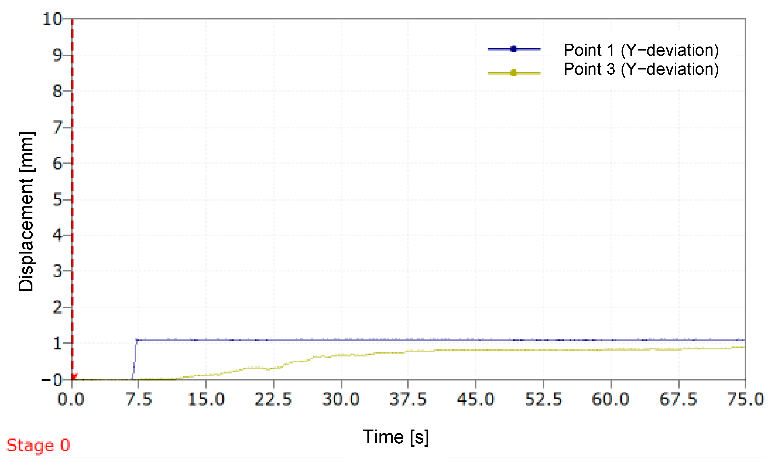
The results for the displacement generated by a simulated LLD of 1 mm and 10 mm are presented below.
Figure 11 illustrates the variation in deviation along the
Y-axis over time for two distinct points (P1 and P3) during a simulation of a 1 mm LLD. Stage 0 represents the starting point of the DIC measurement process.
A sudden increase in the displacement curve of P1 is observed around the value of 1 mm, consistent with the introduction of the standardized 1 mm plate used to simulate the limb length discrepancy (LLD). After a short period, the curve stabilizes. For P2, positioned on the movable component of the MOPE, the curve shows a continuous increase in the initial seconds, followed by stabilization, with the maximum displacement value approaching 1 mm. The relative error with which the prosthesis compensated for the simulated LLD is 8.8%.
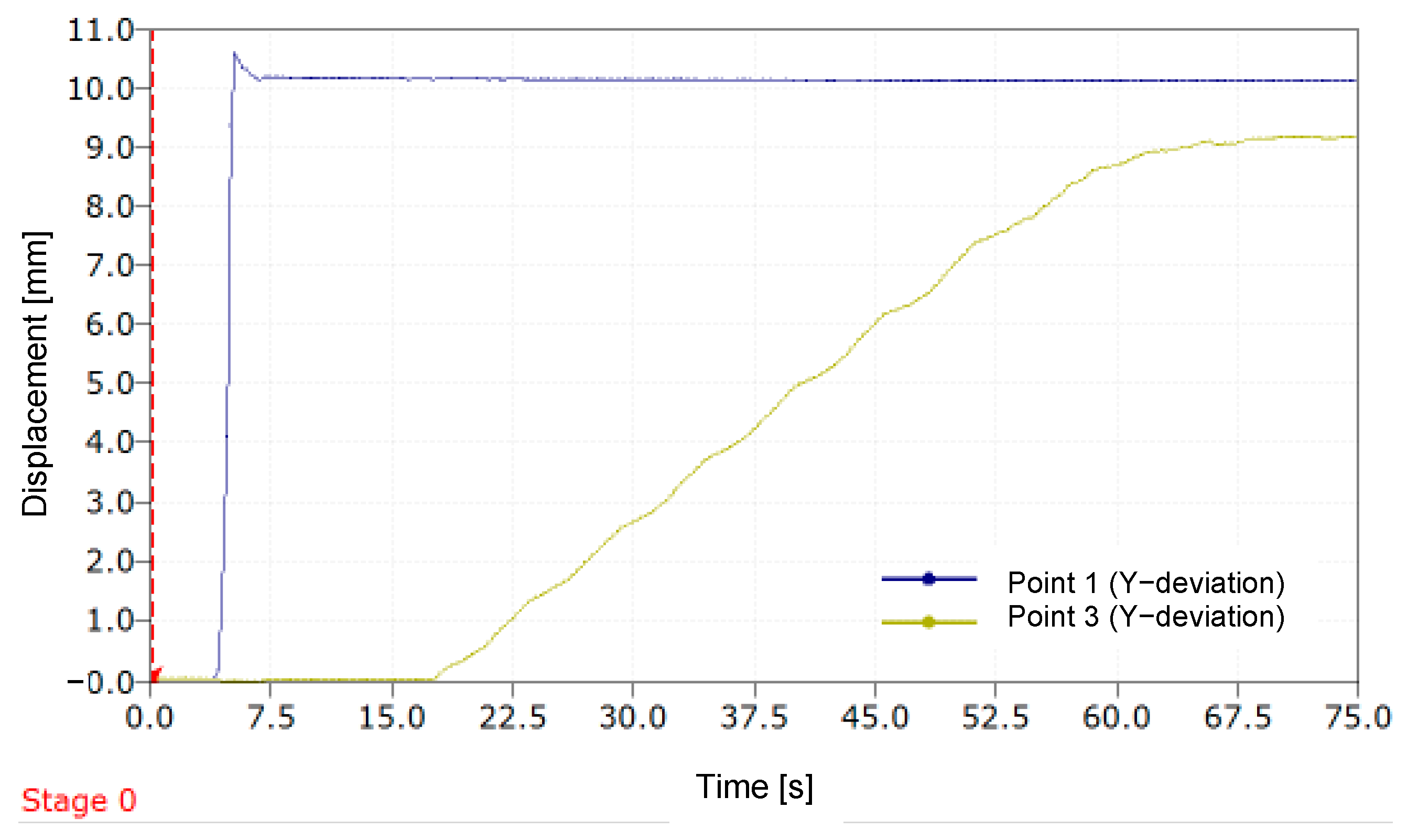
In
Figure 12, which is analogous to
Figure 11, it can be observed that the prosthesis compensates for an LLD exceeding 9.2 mm when a simulated LLD is induced using a 10 mm plate.
In this instance, the relative error value with which the mannequin’s leg length discrepancy was compensated is 7.2%.
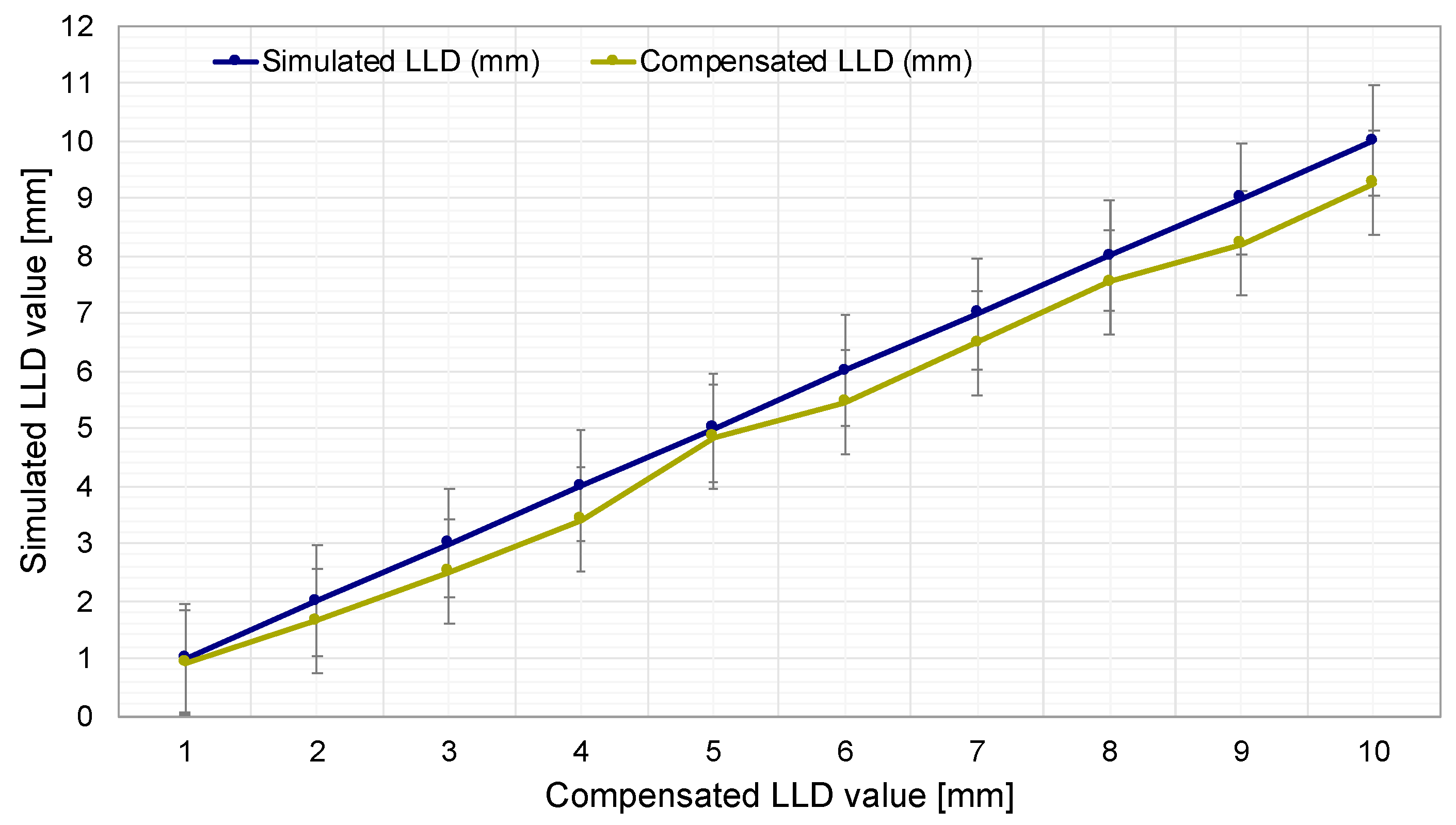
As illustrated in
Figure 13, the simulated LLD values (blue curve) are shown, ranging from 1 mm to 10 mm with 1 mm increments. This enables an assessment of the impact of leg length discrepancy on the measurement and compensation system.
Another curve (green) illustrates the evolution of LLD compensation performed by the prosthesis. This curve demonstrates how the prosthesis automatically compensates for length discrepancies based on the simulated LLD values. This visual representation facilitates a direct comparison between the simulated LLD and the prosthesis’s capacity to automatically adjust its length, with an average relative error of 9.8%.
4. Discussion
This prosthetic device was designed to address three main needs in the medical recovery and assistance process for patients with unilateral transtibial amputation: (1) early detection of limb length discrepancy (LLD) without the need for frequent visits to the clinician, for preventive purposes; (2) automatic correction of LLD without the assistance of a medical specialist, following an initial calibration; (3) automation of the limb alignment process using a device produced at low cost, suitable for patients in developing countries.
A home-based LLD monitoring and control device, such as the one proposed in this study, can be useful given that patients do not perceive an LLD smaller than 20 mm—a value that is still clinically tolerable [
2,
11]. This discrepancy cannot be effectively managed, as it relies on the presence of a clinician to equalize limb lengths. All prosthetic length adjustments are manually performed by specialists using passive mechanisms [
18,
19,
20,
21,
22,
23,
24,
25,
26,
27,
28], typically occurring only once or twice a year [
17]. During daily use of a standard or bionic prosthesis, without regular adjustment of the prosthetic shaft length, an LLD exceeding the 20 mm threshold becomes harmful. This discrepancy can lead to fatigue and cause significant imbalances in gait biomechanics [
12], potentially resulting in hip or knee osteoarthritis and other mechanical pathologies due to improper load distribution on the shorter limb, specifically the amputated and prosthetic one [
3,
14,
15,
16]. Furthermore, an LLD exceeding 20 mm is perceptible to prosthetic users [
13].
Given that the clinically accepted threshold for LLD is a maximum of 20 mm between a prosthetic limb and an intact limb, and our tests demonstrated that the self-adjusting transtibial prosthesis automatically compensates for LLD with a relative error of 9.8%, the obtained results indicate promising clinical performance. Such an error is considerably low in the context of a 20 mm discrepancy, suggesting that the prosthesis could provide effective correction. The developed prosthesis achieves a performance level sufficient to compensate for most limb length discrepancies within the limits accepted by clinicians.
In terms of accessibility, the self-adjusting prosthesis cannot be directly compared to a traditional prosthesis but rather to a set of classic prostheses of different sizes that need to be replaced approximately twice a year. Thus, the prosthesis proposed here can eliminate the additional costs of frequent replacements and, through its self-adjustability, reduce the need to purchase new prostheses.
Furthermore, the prosthesis reduces the frequency of visits to the prosthetist and long-distance travel, which are costly and difficult for amputees to manage, especially in impoverished regions with a lack of trained prosthetists. Consequently, the self-adjusting prosthesis is more cost-effective in the long term, potentially eliminating the need for prosthetist intervention and providing an economical and accessible solution, even in conditions of limited resources. The authors estimate that such a prosthesis can reduce the cost of adequately fitting a patient with a prosthesis by about 30–40% compared to conventional prostheses. In our estimates, we did not include software development costs. We also do not exclude that the hardware element controlling the prosthesis could be used by multiple patients. For example, a whole group of prosthetized patients from a village in a poor country can benefit from the Master–Slave system of the self-adaptive transtibial prosthesis. This can also reduce costs by eliminating the need for a prosthetist to periodically adjust all these patients.
The CAD design of the prosthesis could be utilized by any individual with access to the requisite software and a manufacturing modality, thereby facilitating prosthesis production in environments with limited resources. Additive manufacturing has the potential to substantially reduce costs and enable local production. Collaborations with non-profit organizations and educational institutions can support the training of local specialists in the creation and fitting of prostheses, while pilot projects can facilitate their deployment in economically disadvantaged regions. Consequently, this technology can become accessible and effective even in regions with limited resources.
The utilization of the self-adjustable transtibial prosthesis is hypothesized to pose minimal challenges in pediatric patients; however, in growing children, circumstances may emerge necessitating frequent prosthesis adjustments. The prosthesis’s adaptable and flexible design facilitates expeditious and effective modifications, ensuring continuous comfort. In instances of sudden and repetitive movements, the lower limbs can be gently stabilized without compromising the LLD evaluation method. For instance, caregivers can employ various engaging methods to attract a child’s attention, enabling the prosthesis accelerometer to swiftly detect LLD. This approach ensures an accurate and efficient assessment of limb length discrepancy without compromising the user’s safety or comfort.
The findings of this study demonstrate that the prototype of the self-adjusting transtibial prosthesis signifies a substantial advancement in the development of an automated LLD compensation system. While its present performance can be regarded as adequate within a clinical context, further testing and clinical validation are imperative to substantiate its performance under diverse conditions. The objective is to undertake additional tests in the future, which has the potential to result in substantial enhancements to the prosthesis’s performance. In addition, we are exploring the development of a contactless LLD detection solution that could enhance the accuracy and fidelity of early discrepancy detection while maintaining a similarly low cost.


 ,
, 


