

Stability Assessment of Gob Side Entry at the Steeply Inclined Mining Face


Abstract
1. Introduction
2. Materials and Methods
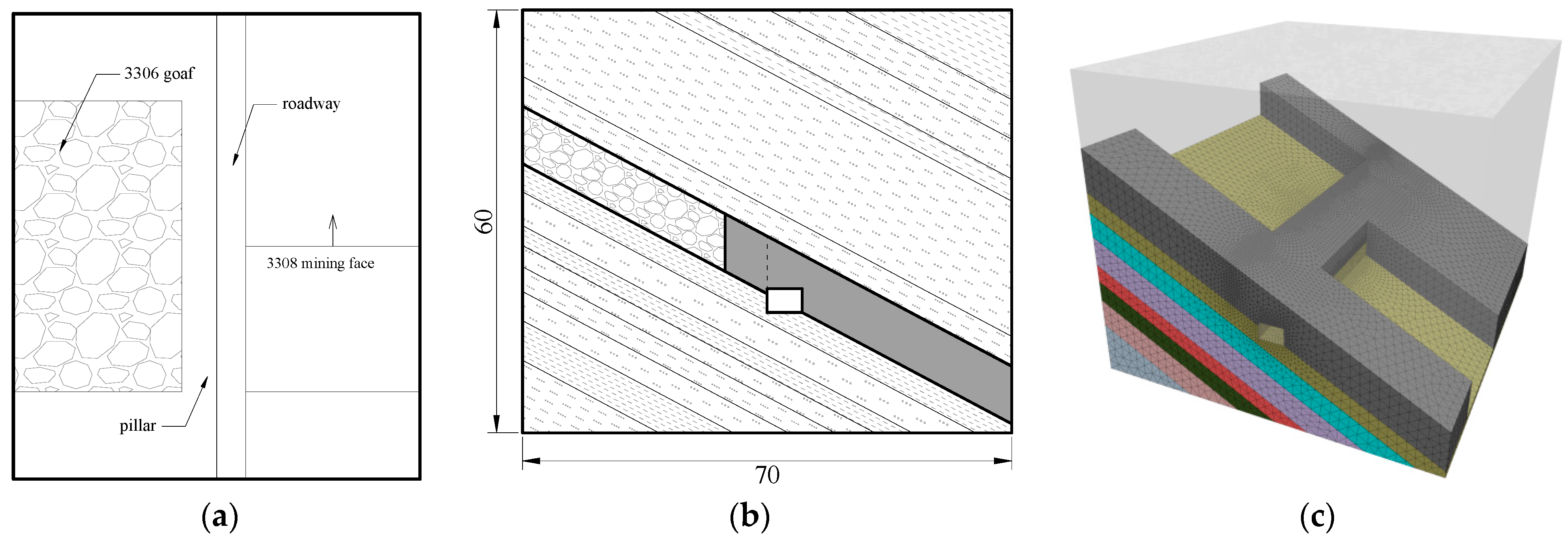
2.1. Brief of the Case
- (1)
- Buried Depth
- (2)
- Strata Thickness and Lithology
- (3)
- Geological Structure and Tectonic Stress
- (4)
- Stratigraphic Dip
2.2. In Situ Stress Measurement
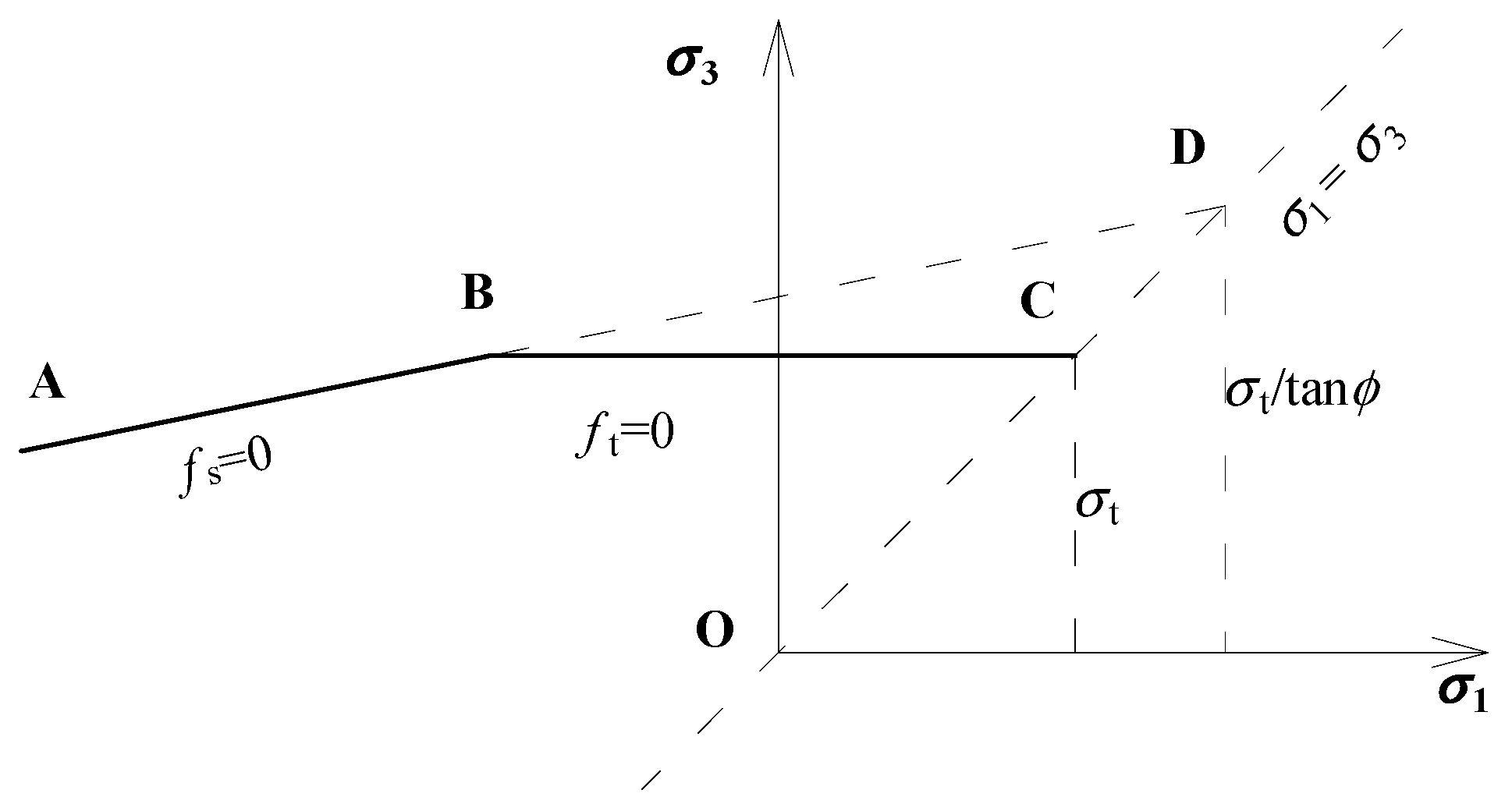
2.3. Numerical Simulation
2.4. Roadway Displacement Measurement
3. Results
3.1. Geostress
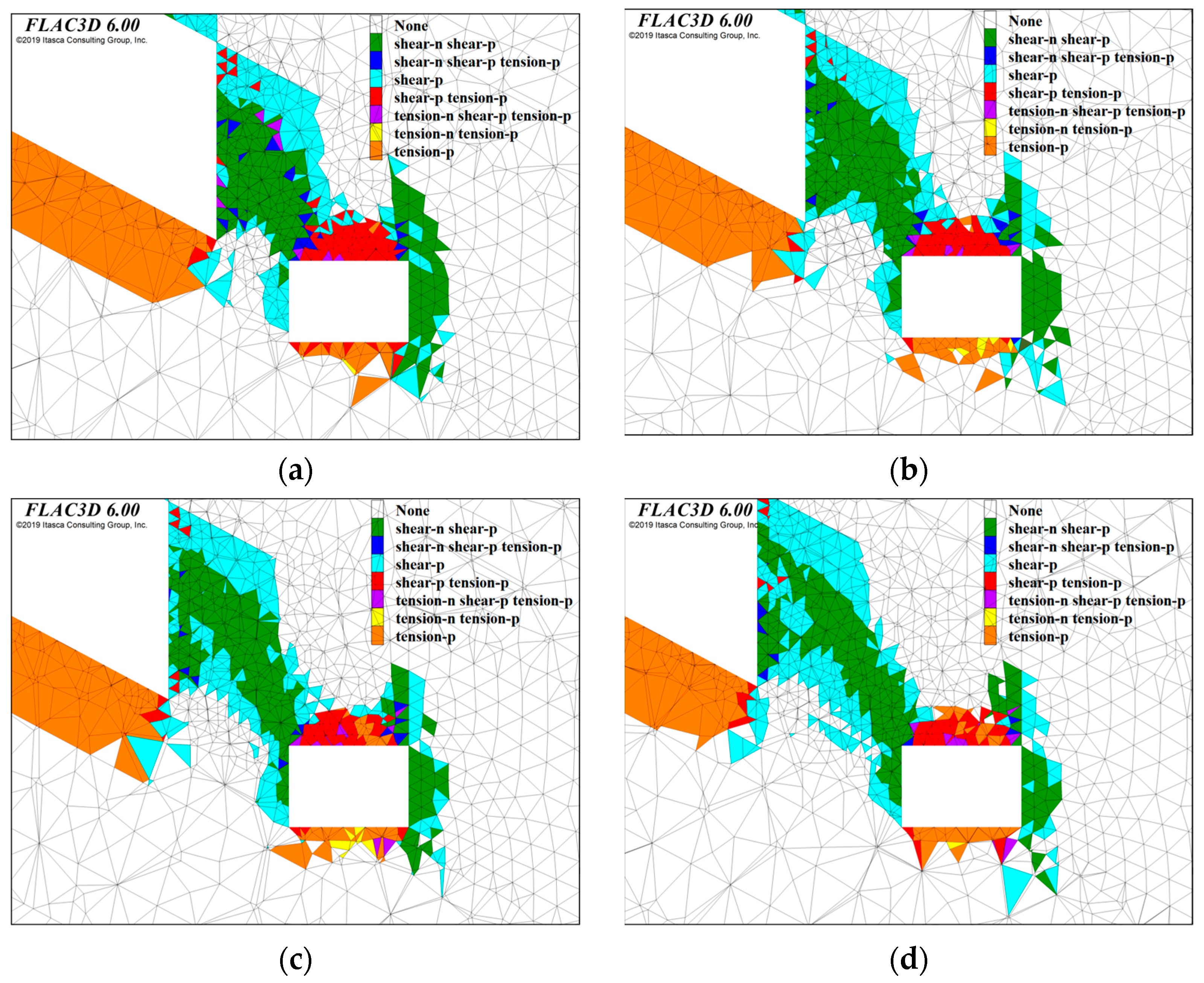
3.2. Coal Pillar Width Analysis
- (1)
- Vertical Stress
- (2)
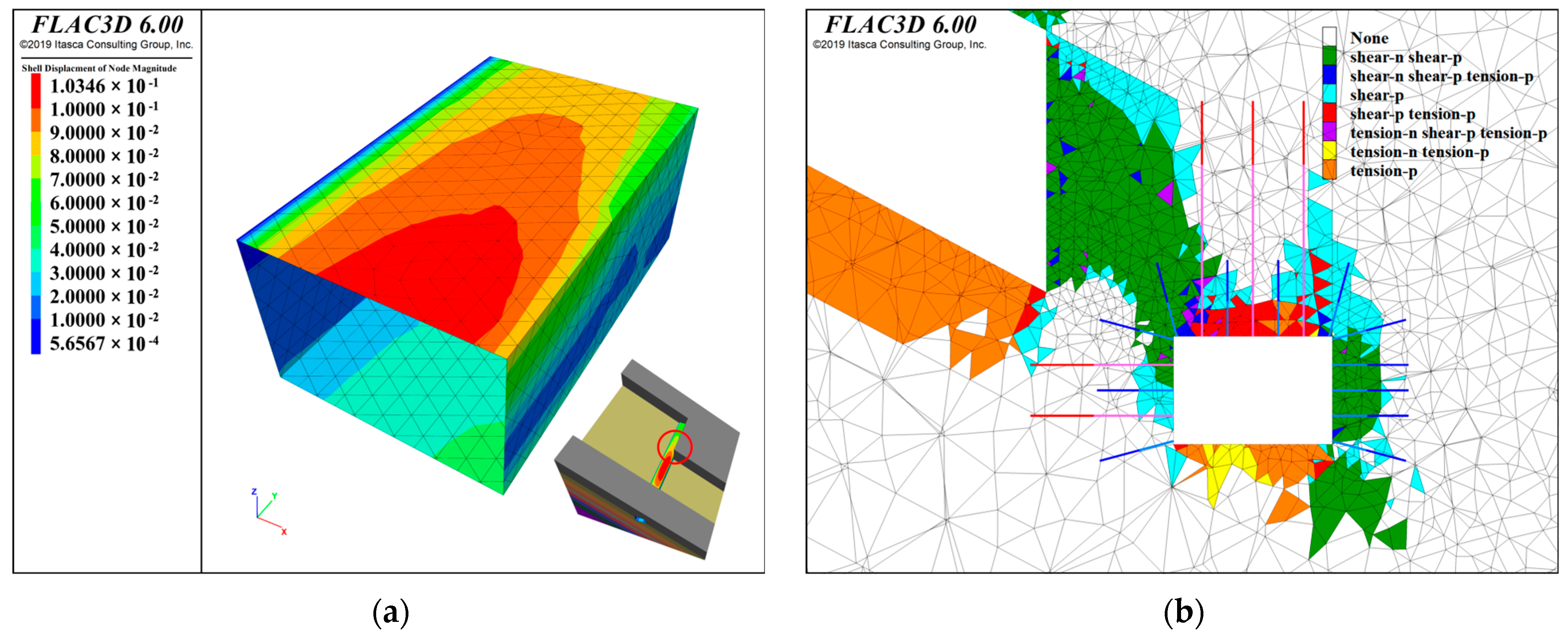
- Plasticity State
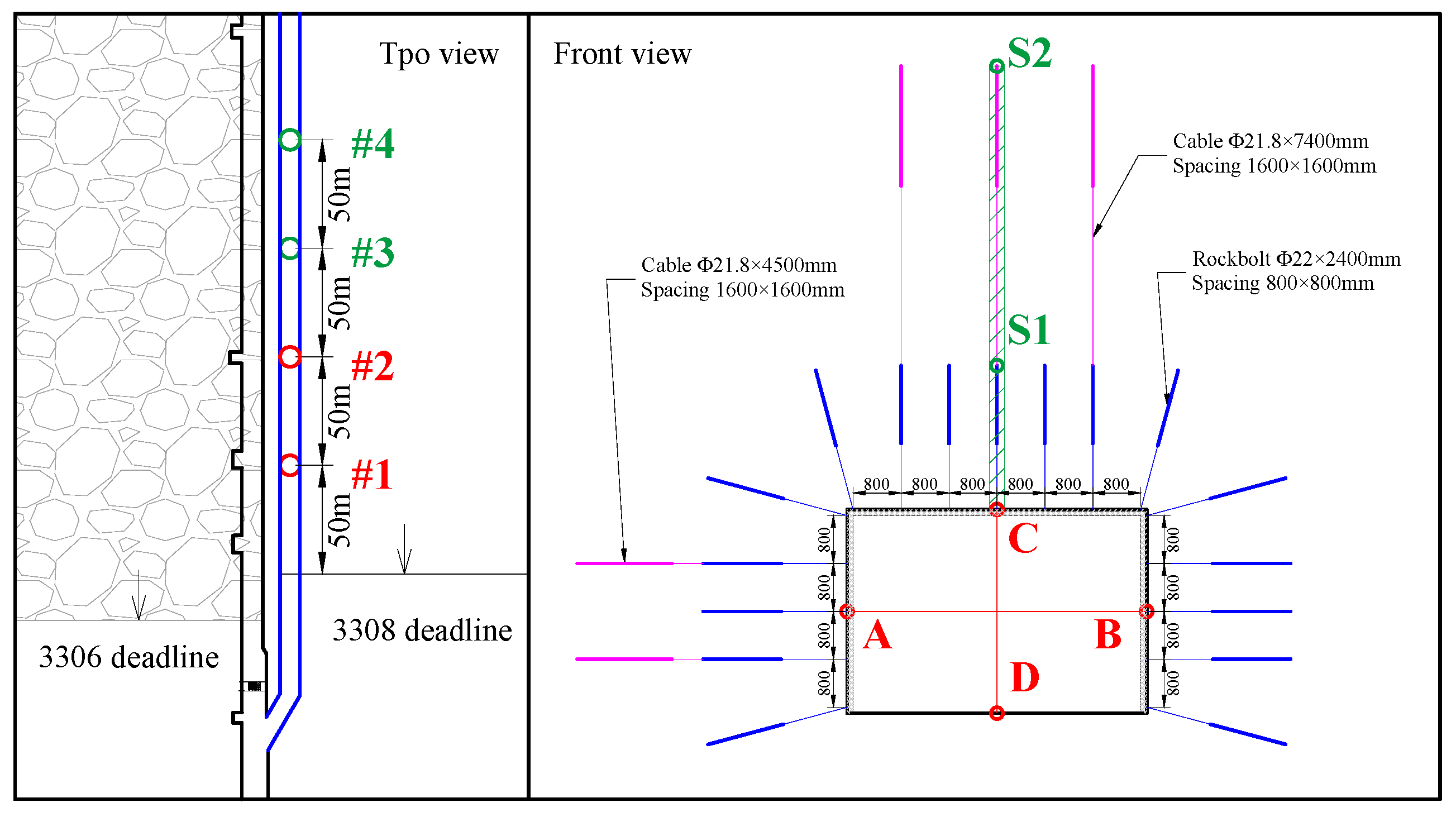
3.3. Support Scheme
- (1)
- Rock Bolt
- (2)
- Anchor Cable
- (3)
- Steel Mesh
3.4. Support Effect
- (1)
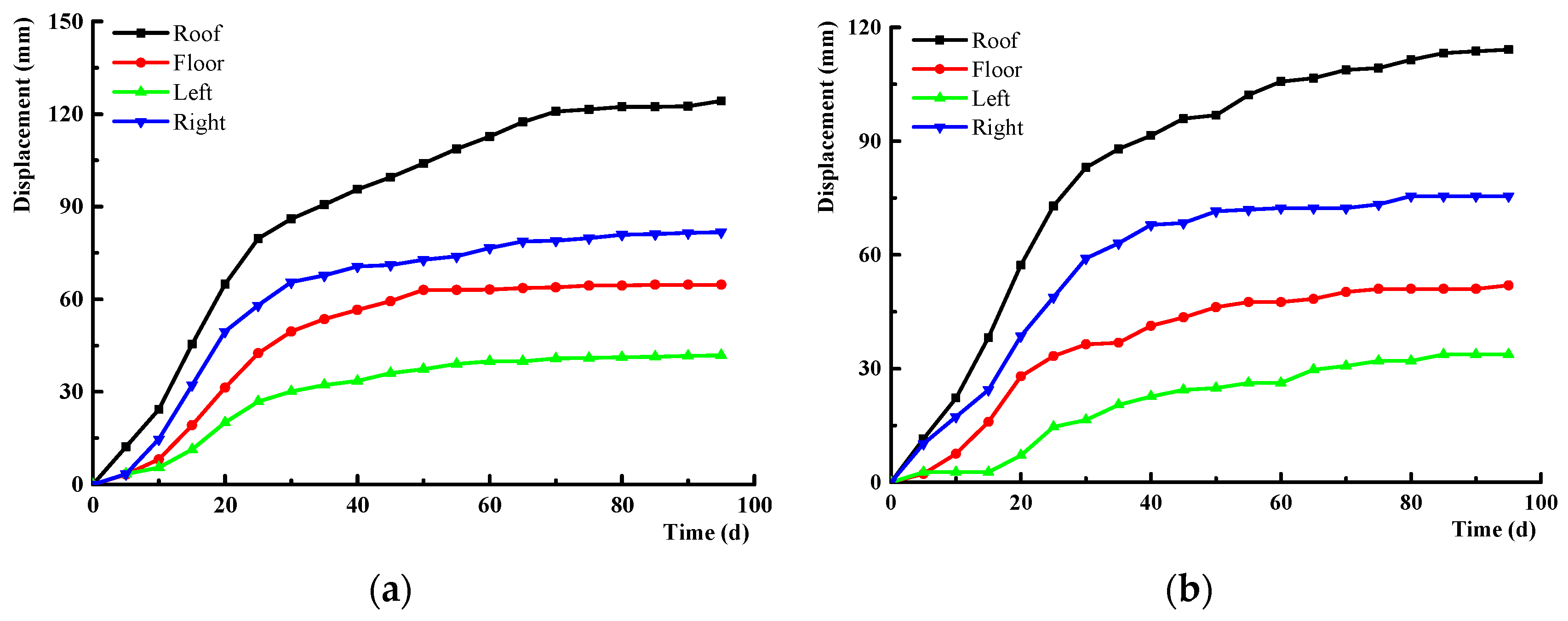
- During the initial phase of 3308 track entry driving, the displacement variation is significant, exhibiting a rapid upward trajectory. The support resistance escalates with deformation. The roadway deformation stabilized after 70 days of support application, signifying that the surrounding rock stress attained equilibrium.
- (2)
- The change size of roadway displacement is as follows: roof > solid coal side > floor > pillar side. Subsequent to the stabilization of the surrounding rock deformation, the roof subsidence measures 120~130 mm. The floor heave measures 50~60 mm. The lateral displacement of the solid coal is approximately 70~80 mm. The pillar displacement measures 30~40 mm. The deformation of the two sections is asymmetric, although the displacement remains within the acceptable limit.
- (3)
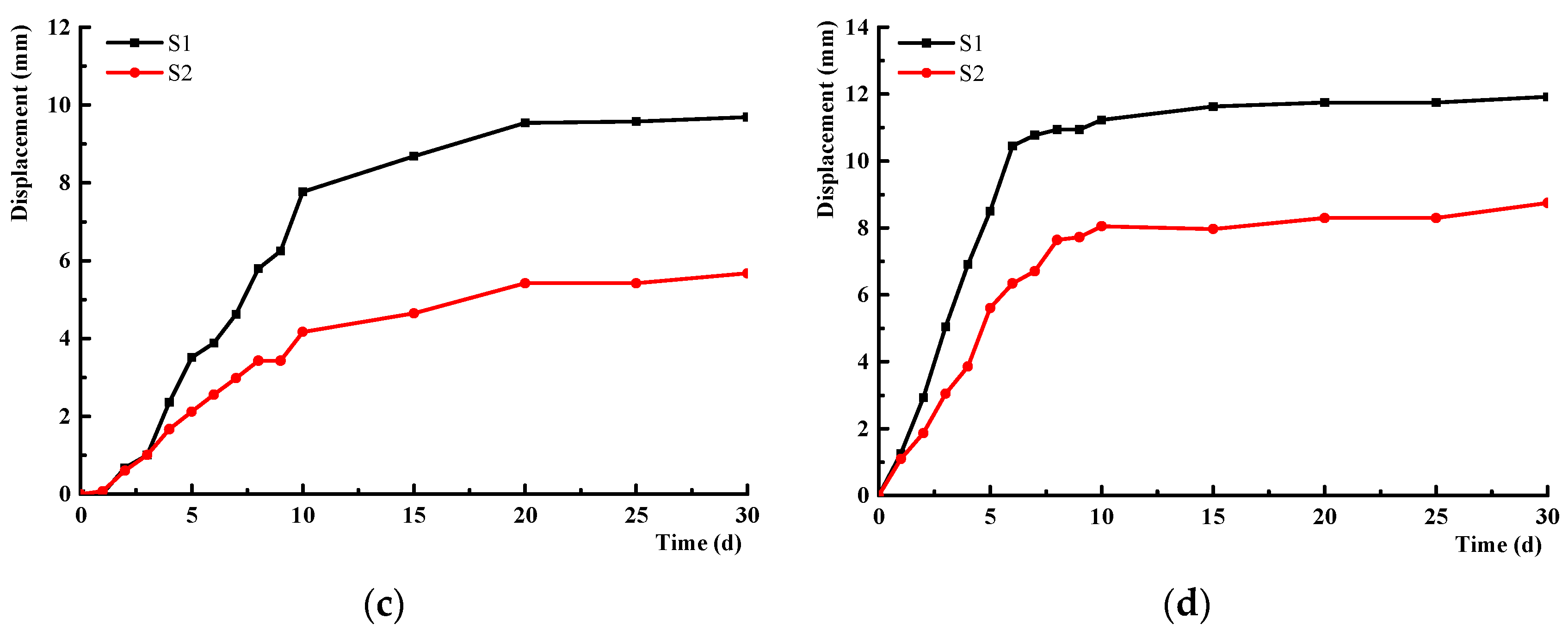
- Following the excavation of the roadway, the stability of the roof is augmented. Ten days prior to the roadway excavation, the expansion rate of the separation layers is considerably high. As monitoring time increases, the internal deformation rate of the surrounding rock progressively diminishes. The roof crack’s maximum width is around 12 mm. The monitoring results indicate that the support strategy can significantly diminish layer separation.
4. Discussion
- (1)
- High-Stiffness Rock Bolt
- (2)
- Anchor Cable
- (3)
- Strengthen the Coal Pillar
5. Conclusions
- (1)
- Analyzing the pillar width in the context of a significant inclination angle. When the breadth of the coal pillar ranges from 3~6 m, the surrounding rock pressure is consistently asymmetric. The pillar and roof possess the primary reinforcement zone for surrounding rock stabilization. The displacement of the roadway exhibits an asymmetric characteristic relative to the roof, solid coal side, and pillar side. The plastic zone consistently exhibited an unequal distribution in its width. A thorough assessment of stress and plastic area parameters indicates that the optimal coal pillar width is 4 m.
- (2)
- Proposing control measures for the gob side entry. The proposed essential technology for surrounding rock control is based on the features of stress and the plasticity state. Utilizing high-stiffness (500 MPa) rock bolt, the size is Φ 22 × 2400 mm and the spacing measures 800 × 800 mm. The stiffness of cable is 1860 MPa and the spacing measures 1600 × 1600 mm. The size of roof cable and pillar cable is Φ 21.8 × 7400 mm and Φ 21.8 × 4500 mm, respectively. After 70 days of support application, the maximum displacement is measured on roof, with a reasonable value of 130 mm.
Author Contributions
Funding
Institutional Review Board Statement
Informed Consent Statement
Data Availability Statement
Acknowledgments
Conflicts of Interest
References
- Wang, Q.; Jiang, Z.; Jiang, B.; Gao, H.; Huang, Y.; Zhang, P. Research on an automatic roadway formation method in deep mining areas by roof cutting with high-strength bolt-grouting. Int. J. Rock Mech. Min. Sci. 2020, 128, 104264. [Google Scholar] [CrossRef]
- Ranjith, P.G.; Zhao, J.; Ju, M.; De Silva, R.V.S.; Rathnaweera, T.D.; Bandara, A.K.M.S. Opportunities and Challenges in Deep Mining: A Brief Review. Engineering 2017, 3, 546–551. [Google Scholar] [CrossRef]
- Zha, W.; Shi, H.; Liu, S.; Kang, C. Surrounding rock control of gob-side entry driving with narrow coal pillar and roadway side sealing technology in Yangliu Coal Mine. Int. J. Min. Sci. Technol. 2017, 27, 819–823. [Google Scholar] [CrossRef]
- Bai, J.-b.; Shen, W.-l.; Guo, G.-l.; Wang, X.-y.; Yu, Y. Roof Deformation, Failure Characteristics, and Preventive Techniques of Gob-Side Entry Driving Heading Adjacent to the Advancing Working Face. Rock Mech. Rock Eng. 2015, 48, 2447–2458. [Google Scholar] [CrossRef]
- Zhang, Y.; Xia, X.; Sun, X.-m.; Song, P.; Wang, J.; Sun, S.-j.; Chen, C. Research on Coupling Control Technology of Constant Resistance in Gob-side Entry Under Mined Gob of Recent Coal Seam Group. Geotech. Geol. Eng. 2020, 38, 4685–4699. [Google Scholar] [CrossRef]
- Jiang, Y.; Wang, H.; Xue, S.; Zhao, Y.; Zhu, J.; Pang, X. Assessment and mitigation of coal bump risk during extraction of an island longwall panel. Int. J. Coal Geol. 2012, 95, 20–33. [Google Scholar] [CrossRef]
- Zhang, S.; Wang, X.; Fan, G.; Zhang, D.; Jianbin, C. Pillar size optimization design of isolated island panel gob-side entry driving in deep inclined coal seam—Case study of Pingmei No. 6 coal seam. J. Geophys. Eng. 2018, 15, 816–828. [Google Scholar] [CrossRef]
- Fan, L.; Wang, W.; Yuan, C.; Peng, W. Research on large deformation mechanism of deep roadway with dynamic pressure. Energy Sci. Eng. 2020, 8, 3348–3364. [Google Scholar] [CrossRef]
- Zang, C.; Chen, M.; Zhang, G.; Wang, K.; Gu, D. Research on the failure process and stability control technology in a deep roadway: Numerical simulation and field test. Energy Sci. Eng. 2020, 8, 2297–2310. [Google Scholar] [CrossRef]
- Liu, F.; Han, Y.; Liu, J. Deformation Mechanism and Control of the Surrounding Rock during Gob-Side Entry Driving along Deeply Fully Mechanized Caving Island Working Face. Geofluids 2021, 5515052. [Google Scholar] [CrossRef]
- Yang, J.; Cao, S.; Li, X. Failure laws of narrow pillar and asymmetric control technique of gob-side entry driving in island coal face. Int. J. Min. Sci. Technol. 2013, 23, 267–272. [Google Scholar] [CrossRef]
- Jiang, B.; Wang, L.; Lu, Y.; Wang, C.; Ma, D. Combined early warning method for rockburst in a Deep Island, fully mechanized caving face. Arab. J. Geosci. 2016, 9, 743. [Google Scholar] [CrossRef]
- Qian, D.; Zhang, N.; Shimada, H.; Wang, C.; Sasaoka, T.; Zhang, N. Stability of goaf-side entry driving in 800-m-deep island longwall coal face in underground coal mine. Arab. J. Geosci. 2016, 9, 82. [Google Scholar] [CrossRef]
- He, H.; Sun, L.; Su, S.; Yang, B.; Yi, P. Study on Strata Behavior Law and Support Adaptability in Fault Island Pillar Light Caving Face. Procedia Earth Planet. Sci. 2011, 2, 40–43. [Google Scholar] [CrossRef]
- Zhu, G.-a.; Dou, L.-m.; Wang, C.-b.; Li, J.; Cai, W.; Ding, Z.-w. Numerical investigation of the evolution of overlying strata and distribution of static and dynamic loads in a deep island coal panel. Arab. J. Geosci. 2017, 10, 549. [Google Scholar] [CrossRef]
- Ye, Q.; Wang, G.; Jia, Z.; Zheng, C.; Wang, W. Similarity simulation of mining-crack-evolution characteristics of overburden strata in deep coal mining with large dip. J. Pet. Sci. Eng. 2018, 165, 477–487. [Google Scholar] [CrossRef]
- Liang, Z.; Song, W.; Liu, W. Theoretical models for simulating the failure range and stability of inclined floor strata induced by mining and hydraulic pressure. Int. J. Rock Mech. Min. Sci. 2020, 132, 104382. [Google Scholar] [CrossRef]
- Cheng, Q.; Shi, Y.; Zuo, L. Numerical Simulation and Analysis of Surface and Surrounding Rock Failure in Deep High-Dip Coal Seam Mining. Geotech. Geol. Eng. 2019, 37, 4285–4299. [Google Scholar] [CrossRef]
- Chi, X.; Yang, K.; Wei, Z. Breaking and mining-induced stress evolution of overlying strata in the working face of a steeply dipping coal seam. Int. J. Coal Sci. Technol. 2021, 8, 614–625. [Google Scholar] [CrossRef]
- Yang, Z.; Liu, C.; Tang, S.; Dou, L.; Cao, J. Rock burst mechanism analysis in an advanced segment of gob-side entry under different dip angles of the seam and prevention technology. Int. J. Min. Sci. Technol. 2018, 28, 891–899. [Google Scholar] [CrossRef]
- Chang, Q.; Tang, W.; Xu, Y.; Zhou, H. Research on the width of filling body in gob-side entry retaining with high-water materials. Int. J. Min. Sci. Technol. 2018, 28, 519–524. [Google Scholar] [CrossRef]
- Wu, W.-d.; Bai, J.-b.; Wang, X.-y.; Yan, S.; Wu, S.-x. Numerical Study of Failure Mechanisms and Control Techniques for a Gob-Side Yield Pillar in the Sijiazhuang Coal Mine, China. Rock Mech. Rock Eng. 2018, 52, 1231–1245. [Google Scholar] [CrossRef]
- Sun, Q.; Zhang, J.; Huang, Y.; Yin, W. Failure Mechanism and Deformation Characteristics of Gob-Side Entry Retaining in Solid Backfill Mining: A Case Study. Nat. Resour. Res. 2019, 29, 2513–2527. [Google Scholar] [CrossRef]
- Guo, P.; Ren, D.; Xue, Y. Simulation of multi-period tectonic stress fields and distribution prediction of tectonic fractures in tight gas reservoirs: A case study of the Tianhuan Depression in western Ordos Basin, China. Mar. Pet. Geol. 2019, 109, 530–546. [Google Scholar] [CrossRef]
- Matsumoto, S.; Nakao, S.; Ohkura, T.; Miyazaki, M.; Shimizu, H.; Abe, Y.; Inoue, H.; Nakamoto, M.; Yoshikawa, S.; Yamashita, Y. Spatial heterogeneities in tectonic stress in Kyushu, Japan and their relation to a major shear zone. Earth Planets Space 2015, 67, 172. [Google Scholar] [CrossRef]
- Vo, U.D.; Chang, C. Geomechanical characterization of sedimentary basins using tectonic stress and strain. Geosci. J. 2020, 24, 669–678. [Google Scholar] [CrossRef]
- Zhang, F.; Lu, X.; Botterill, S.; Gingras, M.; Zhuo, Q.; Zhong, H. Horizontal tectonic stress as a cause of overpressure in the southern margin of the Junggar Basin, northwest China. J. Pet. Sci. Eng. 2021, 205, 108861. [Google Scholar] [CrossRef]
- Yang, S.-Q.; Chen, M.; Jing, H.-W.; Chen, K.-F.; Meng, B. A case study on large deformation failure mechanism of deep soft rock roadway in Xin’An coal mine, China. Eng. Geol. 2017, 217, 89–101. [Google Scholar] [CrossRef]
- Li, S.C.; Wang, Q.; Wang, H.T.; Jiang, B.; Wang, D.C.; Zhang, B.; Li, Y.; Ruan, G.Q. Model test study on surrounding rock deformation and failure mechanisms of deep roadways with thick top coal. Tunn. Undergr. Space Technol. 2015, 47, 52–63. [Google Scholar] [CrossRef]
- Xu, W.; Wang, E.; Shen, R.; Song, D.; Zhang, J. Distribution pattern of front abutment pressure of fully-mechanized working face of soft coal isolated island. Int. J. Min. Sci. Technol. 2012, 22, 279–284. [Google Scholar] [CrossRef]
- Batugin, A.; Wang, Z.; Su, Z.; Sidikovna, S.S. Combined support mechanism of rock bolts and anchor cables for adjacent roadways in the external staggered split-level panel layout. Int. J. Coal Sci. Technol. 2021, 8, 659–673. [Google Scholar] [CrossRef]
- Wang, E.; Xie, S. Determination of coal pillar width for gob-side entry driving in isolated coal face and its control in deep soft-broken coal seam: A case study. Energy Sci. Eng. 2022, 10, 2305–2316. [Google Scholar] [CrossRef]
- Yuan, C.; Wang, W.; Huang, C. A Study on the Mechanism and Controlling Techniques of Roadway Deformations Under High In Situ Stress Conditions. Geotech. Geol. Eng. 2019, 38, 605–620. [Google Scholar] [CrossRef]


| Point | Elevation/m | Location | Direction/° | Dip/° |
|---|---|---|---|---|
| 1# | −650 | Air tunnel for the −650 m phase | 120 | 4.5 |
| 2# | −650 | Air tunnel for the −650 m phase | 113 | 5 |
| 3# | 920 | Belt tunnel for the third mining area | 16 | 4 |
| Lithology | Bulk/GPa | Shear/GPa | Cohesion/MPa | Friction/° | Tension/MPa | Density/(kg/m3) |
|---|---|---|---|---|---|---|
| Packsand | 7.88 | 4.90 | 4.76 | 44.1 | 4.31 | 2750 |
| Siltstone | 6.77 | 3.76 | 4.85 | 39.9 | 5.36 | 2570 |
| Coal | 2.23 | 0.98 | 1.64 | 33.6 | 1.48 | 1450 |
| Mudstone | 4.33 | 2.84 | 0.76 | 39.9 | 3.18 | 2460 |
| Fine sandstone | 9.24 | 5.57 | 2.28 | 42.0 | 5.44 | 2650 |
| Point | Principle | Value/MPa | Direction/° | Dip/° | sv/MPa | sx/σv | s1–s3 | s1/s3 |
|---|---|---|---|---|---|---|---|---|
| #1 | s1 | 21.3 | 119.5 | 5.2 | 14.7 | 1.45 | 13.4 | 2.7 |
| s2 | 12.4 | 9.7 | 75.1 | 0.84 | ||||
| s3 | 7.9 | 210.8 | 13.9 | 0.54 | ||||
| #2 | s1 | 20.2 | 121.2 | 9.3 | 14.7 | 1.37 | 10.2 | 2.0 |
| s2 | 14.7 | −3.9 | 74.1 | 1 | ||||
| s3 | 10.0 | 213.3 | 12.8 | 0.68 | ||||
| #3 | s1 | 35.0 | 161.4 | −6.6 | 23.2 | 1.49 | 15.3 | 1.8 |
| s2 | 23.4 | 28.8 | −80.3 | 1.01 | ||||
| s3 | 19.7 | 252.3 | −7.1 | 0.85 |
Disclaimer/Publisher’s Note: The statements, opinions and data contained in all publications are solely those of the individual author(s) and contributor(s) and not of MDPI and/or the editor(s). MDPI and/or the editor(s) disclaim responsibility for any injury to people or property resulting from any ideas, methods, instructions or products referred to in the content. |
© 2025 by the authors. Licensee MDPI, Basel, Switzerland. This article is an open access article distributed under the terms and conditions of the Creative Commons Attribution (CC BY) license (https://creativecommons.org/licenses/by/4.0/).
Share and Cite
Qin, Z.; Liu, Y.; Zhang, F.; Liu, N. Stability Assessment of Gob Side Entry at the Steeply Inclined Mining Face. Appl. Sci. 2025, 15, 3244. https://doi.org/10.3390/app15063244
Qin Z, Liu Y, Zhang F, Liu N. Stability Assessment of Gob Side Entry at the Steeply Inclined Mining Face. Applied Sciences. 2025; 15(6):3244. https://doi.org/10.3390/app15063244
Chicago/Turabian StyleQin, Zhongcheng, Yongle Liu, Feng Zhang, and Nan Liu. 2025. "Stability Assessment of Gob Side Entry at the Steeply Inclined Mining Face" Applied Sciences 15, no. 6: 3244. https://doi.org/10.3390/app15063244
APA StyleQin, Z., Liu, Y., Zhang, F., & Liu, N. (2025). Stability Assessment of Gob Side Entry at the Steeply Inclined Mining Face. Applied Sciences, 15(6), 3244. https://doi.org/10.3390/app15063244