Article

Mission: Dexterous Functionality—Redesigning the Palmar Configuration Paradigm of Underactuated Prosthetic Hands

1
Department of Engineering Design, Indian Institute of Technology Madras, Chennai 600036, India
2
Department of Applied Mechanics and Biomedical Engineering, Indian Institute of Technology Madras, Chennai 600036, India
*
Author to whom correspondence should be addressed.
Appl. Sci. 2025, 15(6), 3214; https://doi.org/10.3390/app15063214
Submission received: 10 January 2025 / Revised: 6 March 2025 / Accepted: 11 March 2025 / Published: 15 March 2025
(This article belongs to the Section Biomedical Engineering)

Abstract

:

Featured Application

The current work aims to design prosthetic hands with sufficient dexterity and functionality to bridge the gap between research and end-patient utilization.

Abstract

The design of prosthetic hands presents inherent complexities and contradictions that require careful resolution during the initial design phase to achieve a functional solution. This study simplifies prosthetic hand design through an in-depth analysis of the two degrees of freedom (DoF) metacarpophalangeal (MCP) joint, critical in enabling versatile grasping capabilities. Optimal palmar finger orientations were devised using performance metrics, enabling each finger to have 3 DoF while maintaining a simplified mechanical structure. The proposed palmar configuration demonstrated significantly improved grasping performance compared to conventional parallel-fingered designs, accommodating objects of diverse shapes and sizes. A preliminary 3D printed prototype was developed and tested to validate the design. The prototype successfully demonstrated its ability to grasp a wide range of objects, substantiating the efficacy of the novel palmar configuration. This innovative design reduces mechanical complexity without compromising dexterity or functionality. It represents a transformative approach to prosthetic hand development, aligning with the principal goal of enabling users to perform activities of daily living effectively. The findings of this work introduce a novel paradigm in prosthetic hand design, offering a balanced combination of efficiency, dexterity, and practical applicability, thereby advancing the state-of-the-art in prosthetic technology.

1. Introduction

1.1. Background and Motivation

The human hand is a highly intricate kinematic system, possessing 21 degrees of freedom (DoF), excluding the wrist [1], which enables us to perform a vast array of tasks and activities with remarkable precision and adaptability. Designing a prosthetic device to replicate the hand’s capabilities, both in terms of functionality and structure, presents a significant challenge due to inherent contradictions. A prosthetic hand must be simple in design yet possess sufficient dexterity to perform essential functions—tasks that, while seemingly trivial to a human hand, can be exceptionally complex for artificial alternatives [2]. For many decades, researchers have been working to design prosthetic hands that cater to the diverse needs of patients [3,4,5]. The loss of a limb not only hinders an individual’s ability to perform basic motor tasks but also significantly impacts mental well-being, further complicating the recovery process [6].
While a universal prosthetic design may seem ideal, such an approach is counterproductive, as each patient has unique needs and requirements. Researchers worldwide agree that the primary goal of prosthetic hand development is to create devices capable of performing activities of daily living (ADL) [7]. ADLs involve complex kinematic operations that often require coordinated bimanual actions [8], which most current prosthetic hands fail to address fully. Most prosthetic devices available today primarily offer basic grasping and manipulation functions. Since residual electromyography (EMG) signals control most hands, the design complexity is often limited, resulting in prosthetic hands with restricted dexterity and functionality [9]. Therefore, a more targeted and patient-specific approach is essential to improve prosthetic hands, mainly when the goal is to perform the full range of ADLs.
Considerable advancements have been made in recent years to create affordable, functional, and relatively simple prosthetic hands [7]. However, current prosthetic hands still suffer from several significant drawbacks, including (a) insufficient dexterity for fine manipulation, (b) a limited number of joints and degrees of freedom, resulting in restricted movement, and (c) increased design complexity when attempting to integrate the necessary sensors and control systems [10]. The human hand achieves its remarkable dexterity, despite being a kinematically redundant system, due to several key factors: (i) the abundance of musculature in the forearm and palm, (ii) the large number of neurons controlling the hand muscles, (iii) the direct cortical projections onto the motor neurons, and (iv) the intricate network of sensory receptors located on the hand’s surface. These features enable seamless and sophisticated control, allowing the human hand to perform exact movements and adapt quickly to different tasks [11].
In the present study, a mechanical design approach has been utilized to reduce the complexity inherent in the design of prosthetic hands. The primary contributions of this work are as follows:
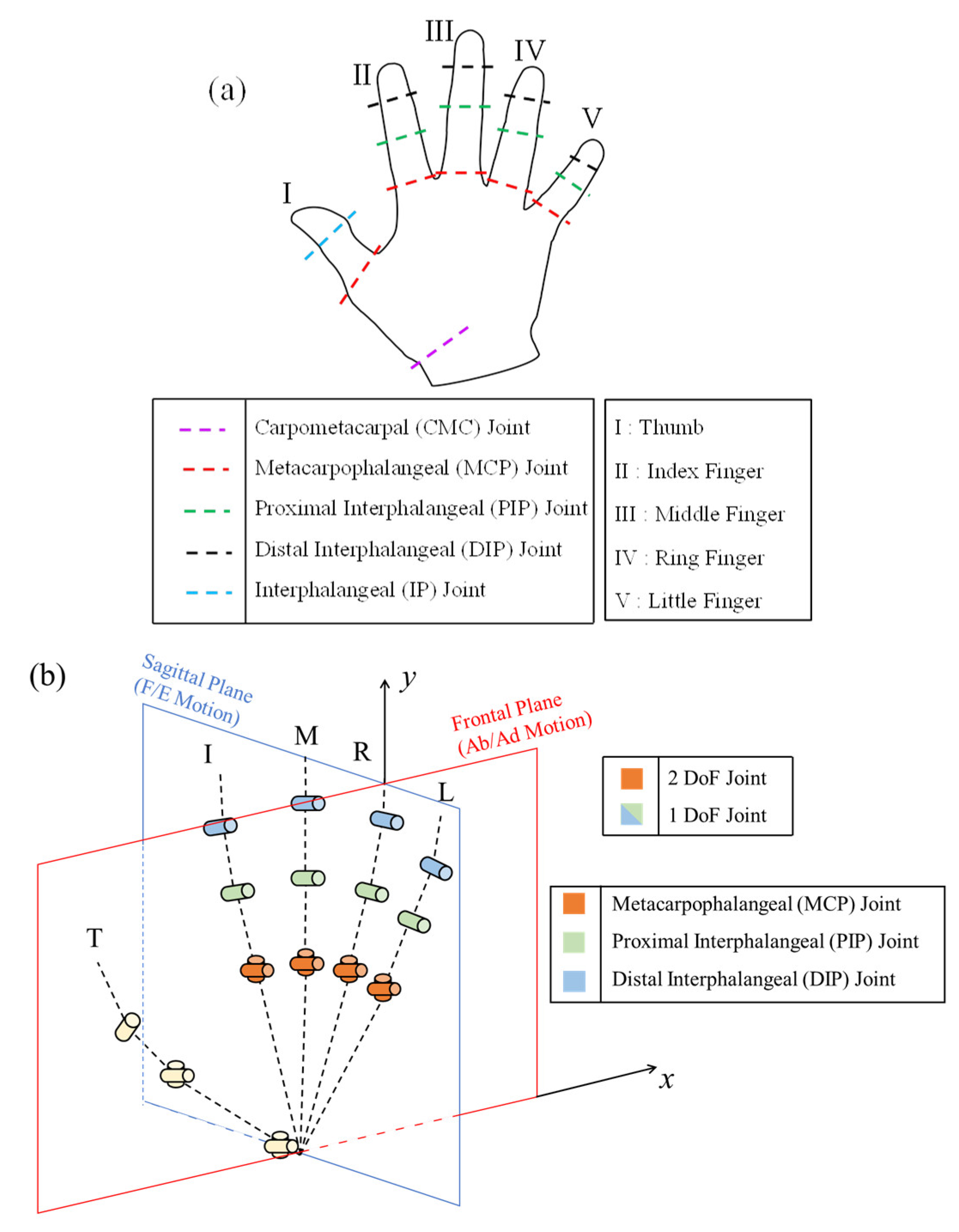
  • The two-DoF metacarpophalangeal (MCP) joint has been selected for analysis to simplify the prosthetic hand design. A novel palmar configuration has been developed since a two-DoF joint introduces significant complexity in both kinematics and control. The design incorporates a one-DoF MCP joint, allowing only flexion/extension (F/E) motion. The simplified configuration is achieved through the application of performance indices.
  • A novel design approach for finger placement based on anatomical and physiological considerations is also proposed, focusing on optimizing size considerations.
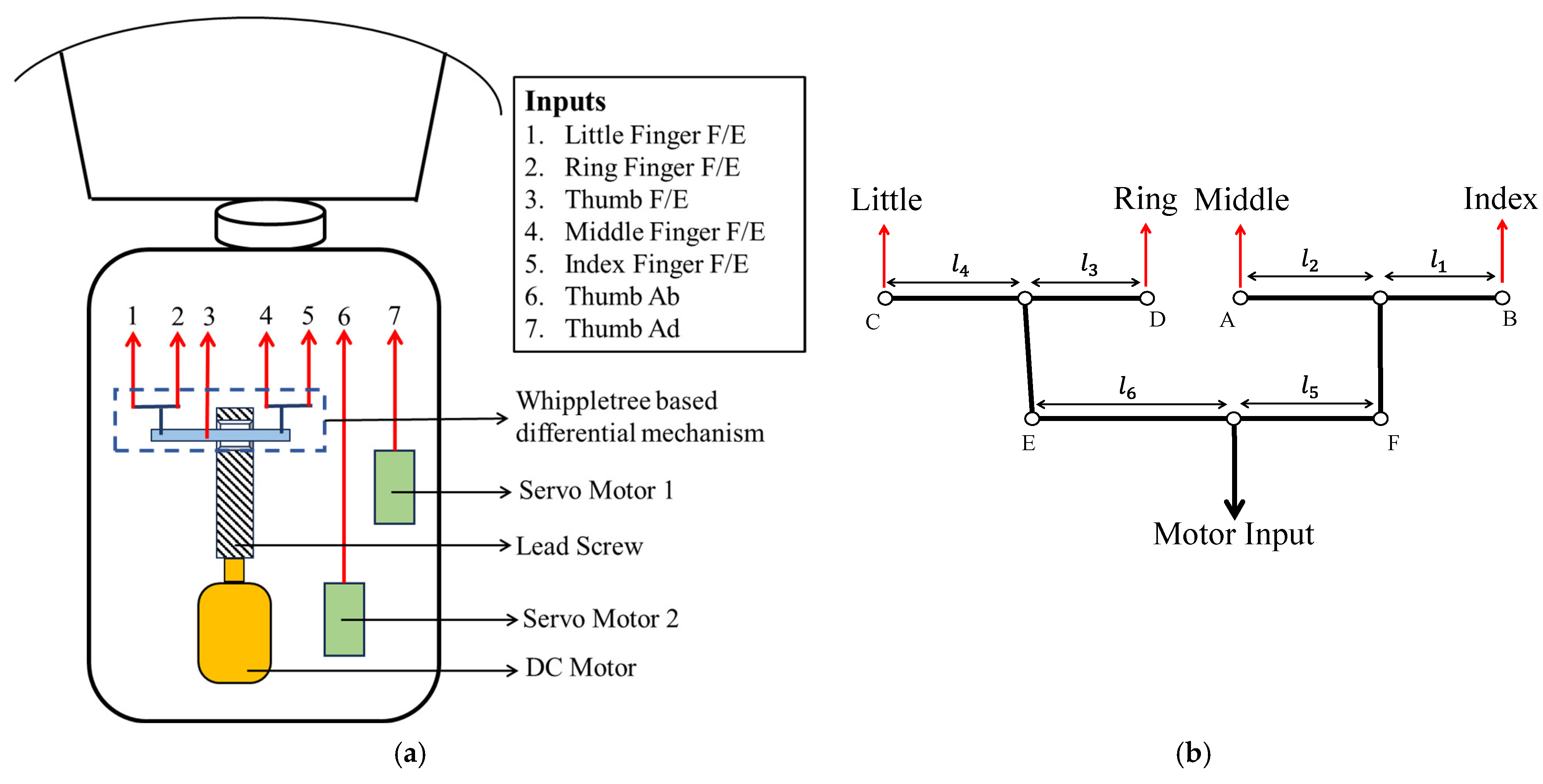
  • A minimalistic motion transmission mechanism that provides a differential input to the finger for anthropomorphic motion is developed. The novel mechanism aims to allow the fingers to grasp objects of various shapes and sizes with sufficient dexterity and stability.
Integrating these contributions results in a prosthetic hand with a simplified design while retaining the ability to grasp various objects. By reducing structural complexity, the need for a less intricate control system is automatically achieved by reducing the number of required control signals. This reduces the resulting prosthetic hand’s cost, weight, and size. The novel design paradigm presented in this paper represents a notable advancement toward developing functional and dexterous prosthetic hands.

1.2. Related Literature

Anthropological and evolutionary studies of the human hand suggest that the fingers are approximately equal in length and arranged in a circular pattern on the palm [12]. Notably, the center of this circular arc is not at the anatomical midpoint of the hand; rather, it lies at the base of the thumb, where the lines of action of the fingers intersect. This configuration facilitates the movement of all fingers and the thumb towards one another, enhancing opposition and increasing finger interaction [13].
Grasping studies of the human hand indicate that it is a two-stage process: (i) prehension, where the arm extends toward the object and the fingers, fully stretched, gradually flex and adduct to conform to the shape and size of the object, and (ii) grasping, where the fingers envelop the object [14]. The number of fingers extended and flexed during grasping depends on both the object grasped and the intended task. Critical to note here is that, during the prehension phase, regardless of the object’s shape and size, the fingers used for grasping achieve their maximum “aperture”, defined as the distance between the tips of the fingers and the thumb. The grasping phase primarily involves finger joint flexion with minimal adduction.
While these insights suggest that a simplified MCP joint design could benefit prosthetic hands, the literature lacks a consensus on optimal finger placement on the palm. Previous analyses of kinematic data from human participants have sought to determine the ideal number of DoF for prosthetic hands, aiming to simplify the design process based on the required manipulations [15]. Kinematic designs for the MCP joint’s planar and spherical mechanisms have been proposed in [16] to minimize coordination errors in abduction/adduction (Ab/Ad) motion. Some studies have attempted to simultaneously actuate both F/E and Ab/Ad motions using flexure-based joints and soft fingers [17]. Other designs have positioned the fingers on a circular arc centered at the MCP joint of the middle finger, with finger inclination based on anatomical and surgical data [18]. Tendon-driven soft fingers were designed to produce 3-dimensional motion by authors in [19].
MCP joint designs commonly reported in the literature include (i) parallel finger configurations without Ab/Ad motion, (ii) four-DoF fingers with active Ab/Ad joints at the expense of simplicity, and (iii) passive Ab/Ad motion via various mechanisms, materials, or control systems, often leading to reduced fingertip force production. Given the need for effective grasping across various object shapes and sizes, incorporating the functionality of Ab/Ad motion into prosthetic hand designs is essential. Therefore, this work seeks to integrate Ab/Ad functionality into a 3-DoF finger design to minimize design complexity. A preliminary design for a complete prosthetic hand is also presented to test and validate the palmar orientation and finger placements. The scope of the current work is limited to finger orientations and locations of the index, middle, ring, and little fingers.
The remainder of this paper is organized as follows: Section 2 analyzes the MCP joint, quantifying its significance and calculating finger configuration based on the MCP joint. Section 3 provides the results of the grasp validation study. A preliminary prosthetic hand design is also provided to validate the theory proposed in the work experimentally. Finally, a discussion and conclusion are provided to end the paper.

2. Materials and Methods

The fingers of the hand have 4 DoF—3 (F/E) motions at the MCP, proximal interphalangeal (PIP), and distal interphalangeal (DIP) joints. The fingers’ MCP joint is unique in that they are 2-DoF joints, allowing the fingers to move in the palmar plane and make out-of-plane motions [20]. These motions help the hand perform numerous postures and grasp objects of various sizes and shapes. Abduction motion is the movement of the finger away from the midline of the palm, whereas adduction motion is the movement toward the center of the palm [20]. Because of the nature of the definition of these movements, the abduction motions of the index and middle fingers are in the opposite direction compared to the ring and little fingers. Further, they also help in performing in-hand manipulations of objects based on task requirements. During in-hand manipulation, the orientation of a grasped object is changed without external support to perform a different task with the said object. The Ab/Ad motion is analyzed to design a palmar configuration for the prosthetic hand to compensate for the dexterity loss arising from 3-DoF fingers. In this context, we analyze the human hand kinematic data obtained through experimentation to quantify and understand the importance of MCP joints during grasping operations. The subsequent sub-sections outline the kinematic experiment that was conducted and the analyses that were performed.

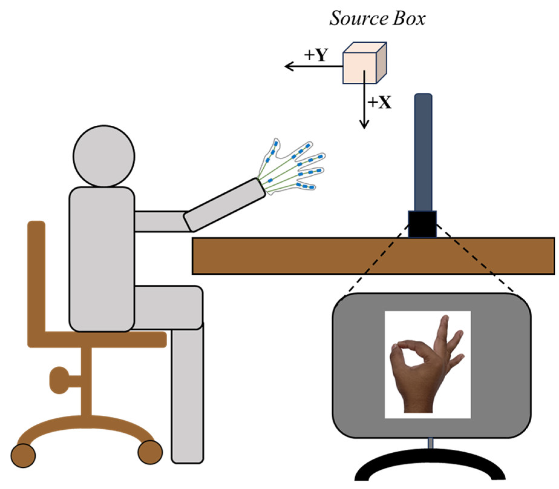
2.1. Kinematic Experiment

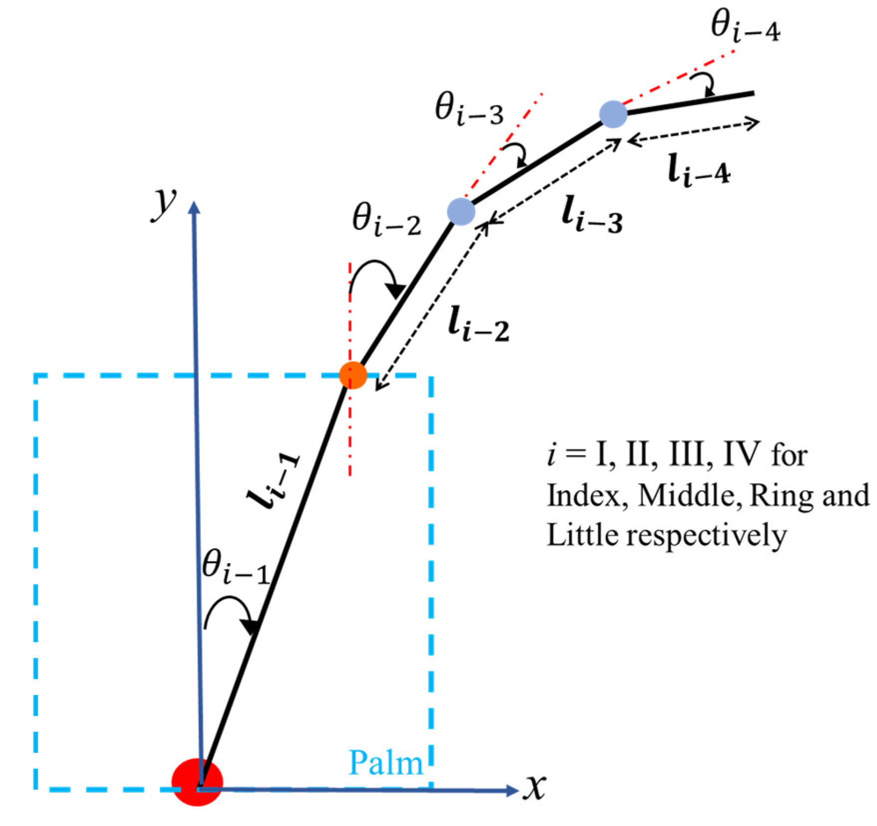
2.1.1. Kinematic Model of the Human Hand

The human hand is a complex mechanical system comprising 19 bones that articulate in 15 joints, excluding the wrist [20]. Hence, it is crucial to formulate a kinematic model of the human hand for experimentation. The model is especially crucial to decide the number and location of the sensors used in the kinematic data collection experiment. The human hand is modelled as a system with 21 DoF for kinematic data collection. The index, middle, ring, and little fingers have 4 DoF each, whereas the thumb is modelled to have 5 DoF for kinematic data collection purposes. The anatomical names of all the hand joints are shown in Figure 1a for reference. The hand model’s kinematic structure and anatomical planes are shown in Figure 1b.

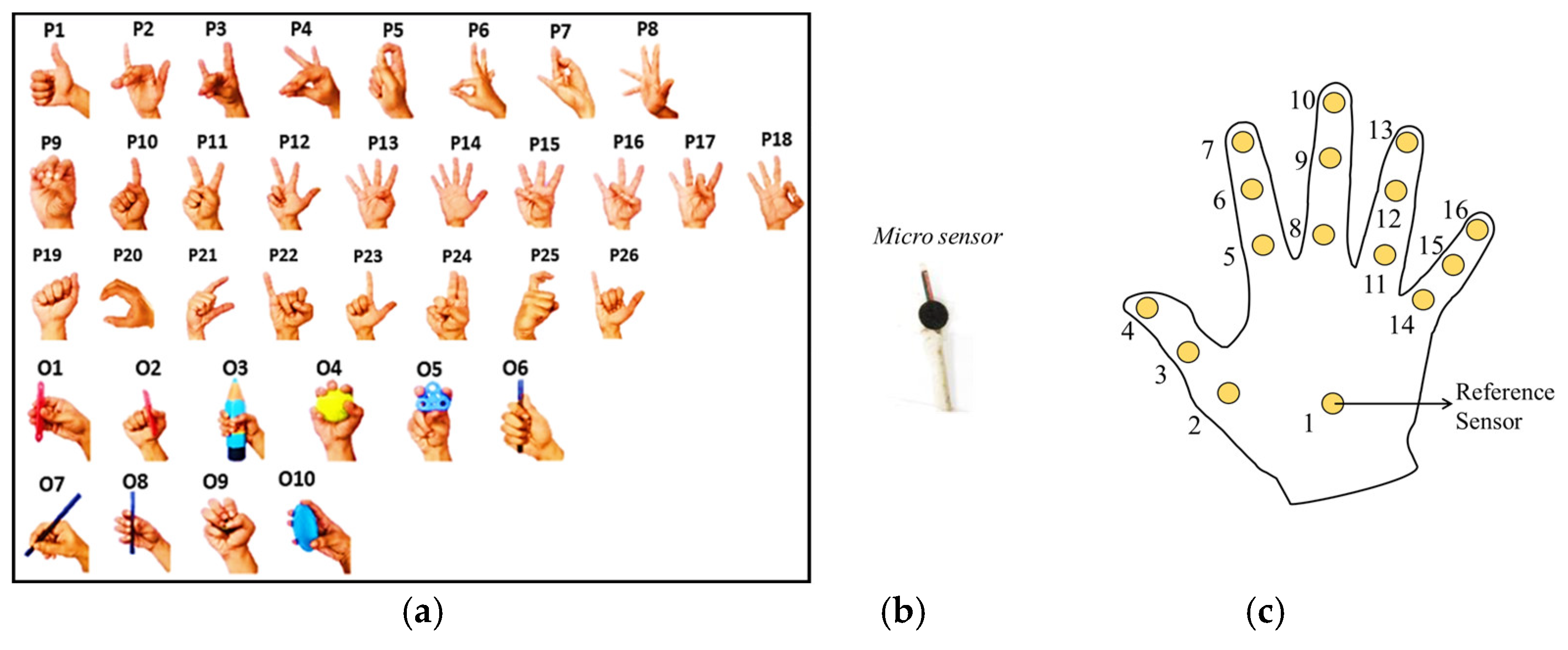
2.1.2. Experiment Design

Ten right-handed participants [5 Males and 5 Females; Age (Mean ± SD)—26.2 ± 3.81 years] took part in the experiment to record hand postures. None of the participants had any history of neuromotor disorders or previous injuries. The IIT Madras ethics committee approved the study (IEC/2020-03/SKM/02/10). During the experiment, the participants were required to perform 26 postures and hold 10 objects, as shown in Figure 2a. The postures were chosen to encompass the different grasps available in the grasp taxonomy as provided in [21]. Each posture/object was repeated for three trials, each lasting 8 s. The data were collected at 100 Hz using a custom LabVIEW (NITM, Austin TX, USA; Version 2017) program. Appendix A and [22] provide additional information regarding the kinematic experiment.

2.1.3. Data Collection and Processing

Position and joint angle data were collected using 16 electromagnetic tracking sensors (Model: Liberty Microsensors, Polhemus Inc., Colchester, VT, USA), as shown in Figure 2b. The microsensors utilized have a diameter of 1.8 mm and a resolution of 1.27 microns. Their static position accuracy is 0.76 mm, while their static angular orientation accuracy is 0.15 degrees. The placement of each sensor on the surface of the palm is shown in Figure 2c. The orientation data from each sensor with respect to the source box were collected in the form of quaternions to avoid singularities in the range of motion. The sensors also output the position data ( x ,   y ,   z ) for each phalanx. Hence, the dimension of the dataset for each trial was 800 rows (8 s × 100 Hz) and 96 columns (16 sensors × 7 readings per sensor). The data collected were filtered with a cutoff frequency of 5 Hz using a linear 2nd order Butterworth filter with zero lag to remove the effects of any physiological tremor. The quaternion data were filtered by converting them into exponential map format [22]. All the data analyses and processing required were performed in MATLAB (MathWorks, Inc., Natick, MA, USA; Version: R2022a). The raw quaternion data were converted into 21 joint angles by relative quaternions using the formula below from [23].
q r e l = q i c o n j     q j
where q r e l is the relative quaternion between quaternions q i and q j measured across any joint k. q i c o n j represents the quaternion conjugate and indicates quaternion multiplication. The relative quaternion thus obtained is converted to Euler angles using the ‘eulerd’ function in MATLAB using “XYZ” as the rotation sequence. The 3 Euler angles represent rotation, Ab/Ad, and F/E according to the sequence. The required angles for each joint were extracted accordingly. Thus, the dataset for each participant has 86,400 rows (36 postures × 3 trials × 800 data points) and 21 columns (21 joint angles).

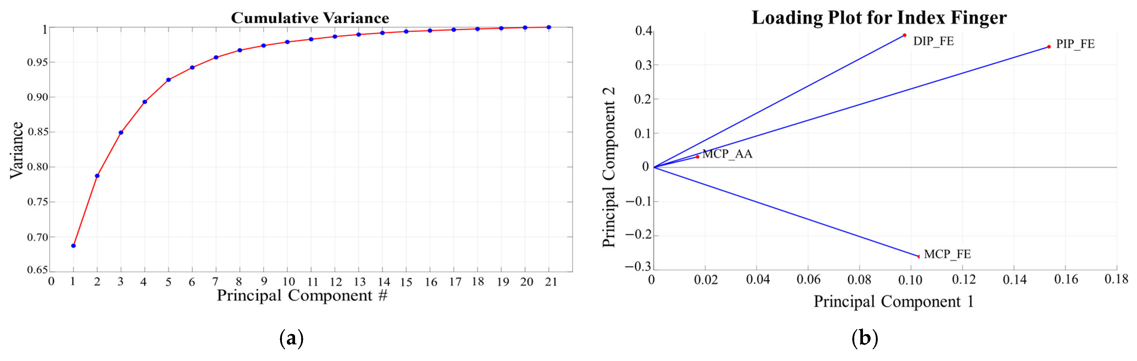
2.1.4. Data Analysis

The data matrix of size 86,400 × 21 was used to perform all the analyses. Identifying the joint angles that have the most significant impact on the overall data variance is crucial. The angles with the highest variance must be actively controlled by external motors in the prosthetic hand design for efficient operation. Principal Component Analysis (PCA) was conducted to analyze the variance of each joint angle. It was observed that the MCP F/E angles have a maximum contribution to the first principal component (PC), indicating their higher variance in grasping. Figure 3a shows the cumulative variance of each PC averaged across participants, postures, and trials. It can be observed that ~85% of the total variance can be expressed by the first 3 PCs as expected [24]. It is also noted that a significant variance of the MCP Ab/Ad angle is observed only in the 3rd PC. This can be attributed to the lower ROM of the MCP Ab/Ad angle. The loading chart of the index finger for the first 2 PCs is shown in Figure 3b. It can be seen that the length of the line segment corresponding to the Ab/Ad angle is quite small when compared to the other three angles of the finger, which shows a lower representation of the MCP Ab/Ad angle in the first two PCs.
Performing only a PCA does not clearly indicate the importance of the Ab/Ad angle in grasping due to the difference in the ROM of the three F/E angles and the Ab/Ad angle. Hence, data normalization needs to be performed to compare variances on a uniform scale. To this end, using the following formula, “min-max normalization” was performed for all the joint angles of the index, middle, ring, and little fingers.
x n e w = x x m i n x m a x x m i n
where x is the data (individual joint angle) value for any joint angle. x m a x and x m i n are the maximum and the minimum values of that joint angle dataset.
The normalized data were then used to perform the variance analysis. The coefficient of variance for the MCP F/E and the Ab/Ad angles was calculated to compare the two joint angles. The results are shown in Figure 4. It was noted that the Ab/Ad angle exhibited a higher coefficient of variance for the index, ring, and little fingers. This finding suggests that the MCP Ab/Ad angle has a significant variance, even within its limited range of motion, highlighting the need to incorporate this functionality into the design of prosthetic hands. Therefore, the role of the Ab/Ad angle should be considered in the design and control of prosthetic hands to enhance overall dexterity and performance.
The current section showed the importance of the Ab/Ad angle and provided the basis for incorporating the functionality of the Ab/Ad angle in prosthetic hand design. This work proposes to design a 3 DoF fingers palmar finger orientation analysis. Orientation of each finger in the current work refers to the Ab/Ad angle as measured in the frontal plane with respect to the y-axis (refer to Figure 1). To this end, in the current work, finger orientation analysis is performed based on the kinematic structure of the finger and the fingertip workspace. Since the finger and hand kinematics have already been established, we continue by performing the workspace analysis of the fingertips.

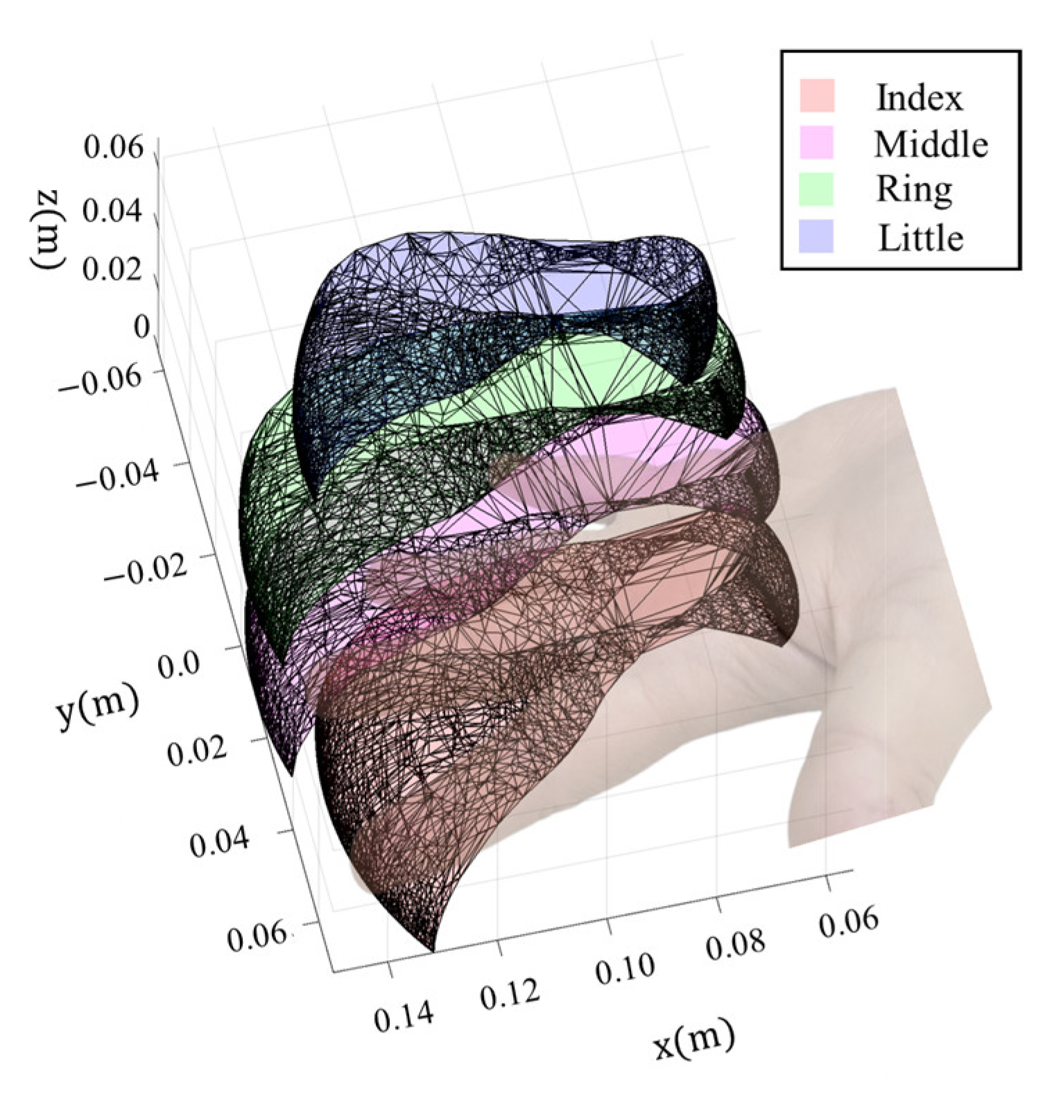
2.2. Finger Workspace Calculation

The finger workspace provides a means to compute various performance parameters, which will then be used to calculate the finger orientation. The fingertip workspace of all the fingers is obtained by performing forward kinematics. Figure 5 shows the kinematic parameters used for workspace calculation. The Denavit–Hartenberg (DH) parameters in Table 1 are used to frame the forward kinematic equations. In the current work, the fingertip workspace is calculated with respect to its base, the MCP joint. Hence, the DH parameters for the index, middle, ring, and little fingers are framed by considering them as 4-DoF serial manipulators.
Using the DH parameters, the workspace boundary for each finger can be traced by considering the anatomical ranges of motion (ROM) for all the hand joints. The joint limits of a human hand, as provided in [25,26], and the ROM for the finger joints, as given in [1,27], are adapted and used in the current work. The ROM for all the joints and the length parameters used in the current work are given in Table 2 and Table 3.
Sign convention for all the angles is considered according to the reference frames shown in Figure 1b. They are as follows—(i) flexion is considered positive whereas hyperextension is written with a negative sign (ii) for Ab/Ad angle, angles measured in counterclockwise direction are considered as positive for mathematical uniformity since abduction motion for index and middle fingers are opposite to ring and little fingers. The workspace boundary for the index, middle, ring, and little fingers are then traced using the sequence of operations as provided in [27]. The fingertip workspace of the index, middle, ring, and little fingers is shown in Figure 6. Since the thumb is not being considered for the analysis, its workspace is not calculated in the current work.

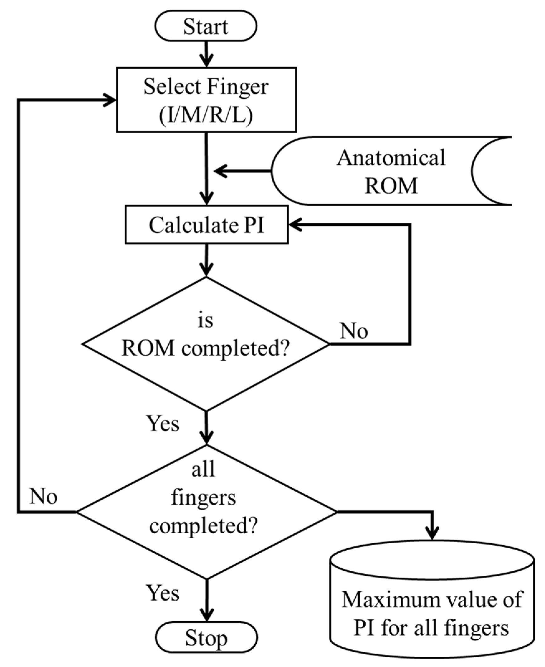
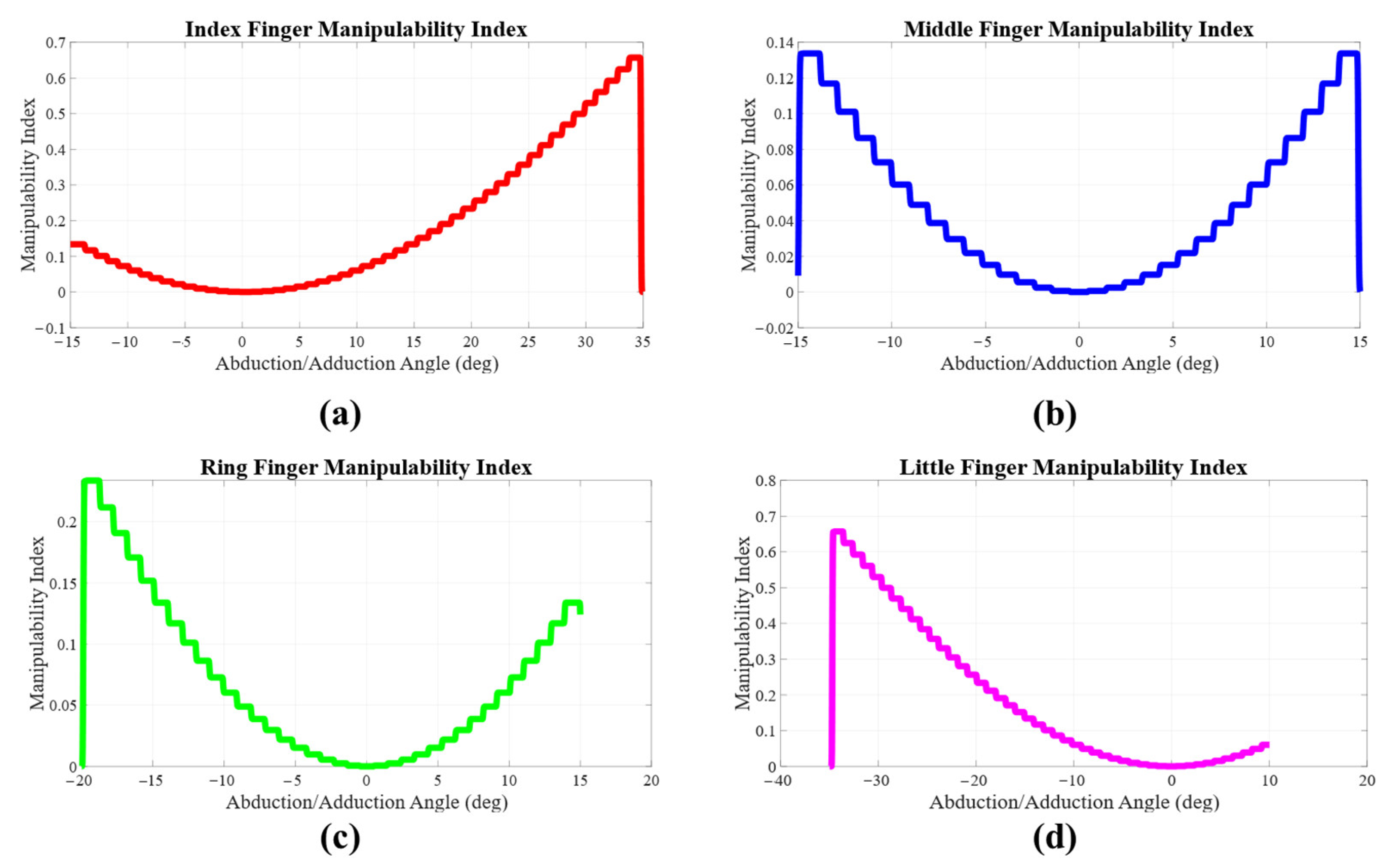
MCP Ab/Ad Joint Calculation

This subsection analyzes the four fingers’ MCP Ab/Ad joint to determine their palmar orientation, enabling the prosthetic hand to achieve 3 DoF for each finger. To optimize finger orientation for enhanced functional dexterity, the manipulability of each finger is evaluated across the full ROM of the MCP Ab/Ad angle. Various performance indices (PIs) commonly employed in evaluating traditional serial manipulators are utilized for this assessment [28]. In this work, the selected PIs are applied either directly or with modifications to the human hand, treating each finger as a serial 4-DoF manipulator to determine the angle for the MCP Ab/Ad joint. The methodology involves calculating the chosen PI for each finger posture across the full ROM of the Ab/Ad joint. The overall methodology employed in this paper for calculating the performance indices (PI) is described in Figure 7. Simulations in a MATLAB environment are used to perform these calculations, with a 1° change in the Ab/Ad angle considered as the step size for determining finger postures. The fingertip positions in the workspace for each posture are then computed. This process is repeated for each finger according to its anatomical ROM. The two PIs listed below were selected for analysis in this study.
(a) Manipulability Index ( μ ): The measure of manipulability or the manipulability index, μ , of a serial manipulator was first defined in 1985 by Yoshikawa [29] as follows
μ J     d e t ( J J T )
where J is the velocity Jacobian matrix of the manipulator. Since the Jacobian matrix of each finger changes for every posture, it is possible to find the posture for which the value of μ will be maximum within the anatomical ROM for each joint of every finger.
The value of μ is calculated for every posture achieved by formulating the Jacobian matrix. The variation of μ for the index, middle, ring, and little fingers across the ROM for the MCP Ab/Ad joint is individually calculated. The variation of μ for the index, middle, ring, and little fingers across the ROM for the MCP Ab/Ad joint is shown in Figure 8. It was observed that the value of μ increases as the absolute value of the Ab/Ad angle increases from 0°. This indicates that, for best performance, the fingers must be placed on the palm at their maximum abducted position. Additionally, it can be inferred from the measure of manipulability that parallel finger arrangement is not ideal for the design of prosthetic hands.
(b) Thumb Opposability Measure ( T ): The performance of any prosthetic hand depends on the level of interaction between the thumb and the fingers. The measure of opposability of the thumb provides the level of interaction between the thumb and the other fingers. The higher the value of the opposability measure, the higher will be the performance of the given hand. The thumb opposability measure T used in this work is obtained by modifying the expression given for the “anthropomorphism index of the kinematic chain” in [30]. The value of T is calculated using the following expression.
T i = w i l t h 2 a i
where T i is the thumb opposability index for the ith finger, a i is the area of intersection between the ith finger and thumb’s workspace, l t h is the length of the thumb, and w i is the numerical weight for calculating the thumb opposability index for each finger. The numerical weight for all four fingers is considered as ‘1’ in the current work for uniformity, as seen in [5]. The Ab/Ad angle for which the value of T (maximum overall intersection area) is highest is chosen. The Ab/Ad angle for the four fingers calculated based on T is provided in Table 4.
Based on the above calculations, we have chosen the results derived from the calculation of T rather than μ . This decision is made because T considers the thumb’s influence on each finger, meaning the performance of any finger is measured in relation to the thumb. In contrast, μ considers the fingers independently and, therefore, cannot provide an accurate measure of overall hand performance. It is important to note that the joint angles for the MCP Ab/Ad joint will significantly influence the PI. In this study, μ was initially considered as a Jacobian matrix-based manipulability measure, the default metric for analysis of serial manipulators.

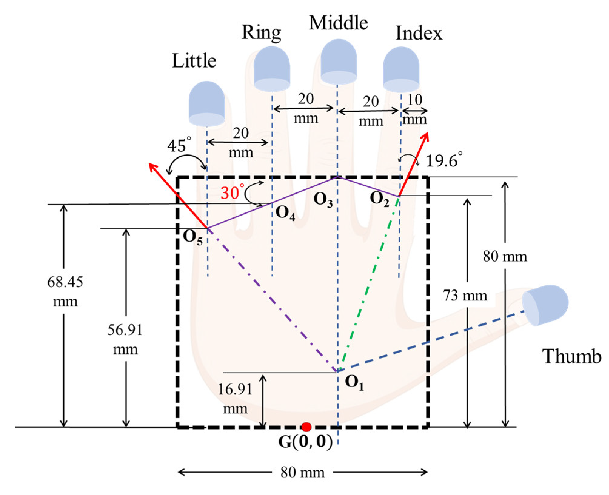
2.3. Location of Finger Bases

The finger orientation design is incomplete without locating the base joints on the palmar surface. The location of the MCP joints plays a critical role in hand dimensions and the overall dexterity of the designed prosthetic hand. The locations of the finger bases on the palm surface shown in Figure 9 are obtained, as explained below. It is also noted that the location of the thumb CMC joint is discussed in this subsection. This is because the location of the MCP joints is directly dependent on the location of the thumb, and it would be impossible to design a functional prosthetic hand otherwise.
The palm is considered to be a square of size 80   m m for calculation, considering anatomical references [25]. The origin G ( 0 , 0 ) is the wrist frame of reference. The vertical lines of action for the index, middle, ring, and little fingers are considered to be equidistant with each other. Based on this consideration, the base of the middle finger O3 is located on the edge of the palmar square. Anatomical and physiological studies of human grasping indicate that a line joining the MCP joint of the middle and little fingers is inclined at an angle of 30 ° with respect to the horizontal when all the fingers are fully flexed [13]. Accordingly, the little finger base O5 is located at the intersection of the vertical and the 30 ° line originating from O3.
Grasping studies of the human hand indicate that the middle, ring, and little fingers converge towards the base of the thumb and index finger [13]. This convergence provides more significant interaction between the thumb and the other fingers, resulting in higher dexterity. Further, the presence of the thenar and hypothenar muscles in the human hand facilitates the interaction between the thumb and the little finger, enabling precise and coordinated movements. However, in prosthetic hands, the thumb is located more toward the base of the middle finger. This design modification is intended to have a 2-fold effect—(i) successful interaction with the little finger and (ii) the ability to perform a lateral pinch in coordination with the index finger. To simplify the location of the thumb base, the CMC joint of the thumb in the current design is assumed to be along the line of action of the middle finger.
The interaction between the thumb and little finger is considered to finalize the location of the thumb CMC joint. The kinematics during the Kapandji test for the thumb dexterity measurement show that the median line of action for the thumb and little finger are collinear during opposition motion [31]. Accordingly, in the current design, the line of action of the little finger at its maximum anatomical abducted position is considered to be the intersection with the thumb CMC joint. Hence, the thumb base O1 is located on the palm surface with the line joining O5 and O1, inclined at 45 ° with respect to the vertical, which is its maximum abducted position [1]. The above considerations provide maximum interaction between the thumb and little finger to enhance grasp stability.
The ring MCP joint O4 is located at the intersection of its vertical line of action and the 30 ° line between O3 and O5. The location of the base of the index finger is critical since the index, middle, and thumb form the tripod grasp, which serves as the primary and most commonly used grasp. The index finger Ab/Ad joint angle was calculated and analyzed to locate its MCP joint. It was observed that the average abduction angle calculated from the experimental data for the index finger was 19.6 ° . Further, the mean of the anatomical ROM for the index finger Ab/Ad joint is 20 ° , which closely matches the experimental average. Hence, the index finger base O2 is located at the intersection of a line inclined at 19.6 ° and the index finger grasp line of action. It is important to note here that the angles calculated/considered in the index and little finger’s location analysis differ from those obtained during finger orientation analysis. The angles in the finger base location analysis refer to the inclination of the line joining the index and little finger base (O2 and O5, respectively) with the thumb base O1. In contrast, the finger orientation angle is the inclination at which all the fingers are placed on the palm surface. The locations of the finger bases O1–O5 are shown in Figure 9, and their coordinates are provided in Table 5.

2.4. Grasp Simulation

Once the MCP Ab/Ad angle for the fingers is calculated, a grasp analysis simulation is performed to validate the angles and test the overall performance. The grasping performance can be assessed through numerous metrics such as the anthropomorphism index, the measure of dexterity, etc., as given in [32]. Prosthetic hands with a high level of anthropomorphism are required to have real-world application and functionality. Hence, a measure of anthropomorphism is usually considered as a measure of grasp quality for prosthetic hands. There are numerous measures of anthropomorphism available in the literature, as in [33,34,35].
In this study, a simulation of a five-fingered grasp was conducted to assess the grasp quality and performance of the designed hand using the SynGrasp toolbox in MATLAB [36]. To validate the design effectively, grasp quality metrics outlined below were applied and compared across three different hands: (i) the human hand, (ii) a prosthetic hand with parallel fingers, and (iii) the current design. The grasp quality metrics used in this study are presented below.
(a) Volume of Manipulability Ellipsoid ( V ): The relationship between the hand space and the object space during the grasping of an object is represented by the hand Jacobian matrix H [37]. The kinematic manipulability of a manipulator is the ability of the end effector (fingertip) to change position and orientation given a joint configuration. To eliminate singular configurations, the objective is to convert the manipulability ellipsoid into a sphere by maximizing the volume of the ellipsoid. The volume of the manipulability ellipsoid is given below
V = k d e t ( H H T ) = k ( σ 1 σ 2 σ 3 σ n )
where σ 1 σ 2 σ 3 σ r are the singular values of the Jacobian matrix H and k is the proportionality constant.
(b) Measure of Finger Interactivity: To validate the design and compare the current and conventional design comprehensively, a second metric is used to measure grasp quality. The interactivity of the fingers with the thumb determines the dexterity of any prosthetic hand. The thumb opposability-based performance index ( T ) considered only the thumb’s length. While this provides information regarding the range of motion of the joints of the hand, it does not provide a complete picture concerning the grasping capability of the hand. The authors of [37] analyzed various grasp quality metrics available in the literature and concluded that performance often depends on the metric. Since the importance of the thumb is widely acknowledged, in this paper, a novel finger interactivity index, I F , is defined to calculate the performance of the hand. This metric has been derived through modifications to the “Opposability of Thumb” measure defined in [5]. It can be expressed as
I F = i = 1 4 w i a i l i d i
where i = 1 to 4 represents the four fingers of the hand, i.e., index, middle, ring, and little finger, respectively. a i is the workspace intersection area of the ith finger with the thumb, l i denotes the length of the ith finger, d i represents the distance from the base (MCP joint) of the ith finger to the base of the thumb, and w i represents the weighting coefficient for the ith finger. For this analysis, the numerical weight for the index, middle, ring, and little fingers are considered to be 1, 0.5, 0.25, and 0.75, respectively. The little finger is provided a higher weightage compared to the middle and ring despite providing a low force output. This is because the little finger can move out of the plane of the palm, similar to the thumb [20]. This capability enables it to provide much-needed stability to the grasped object. Further, this helps the hand in performing in-hand manipulation activities. Hence, the little finger is given a higher weight due to its similarity to the thumb [38].

3. Results

3.1. Finger Configuration

The results of the grasp analysis simulation are provided in Table 6 and Table 7. It can be observed that the grasp performance is better in the current design when compared with the conventional prosthetic hand. This was observed for both V and I F . This can be attributed to the fact that the fingers of the hand approach the objects in different directions, which results in a more stable grasp than parallel fingers.
From the above calculations, it can be inferred that the current design performs better than the conventional prosthetic hand with parallel fingers. It must be noted that the grasping performance for any hand depends on the grasped objects and the intended task. This is because the grasping performance depends on the type of posture and the amount of fingertip force exerted, which, in turn, depends on the two factors listed above.

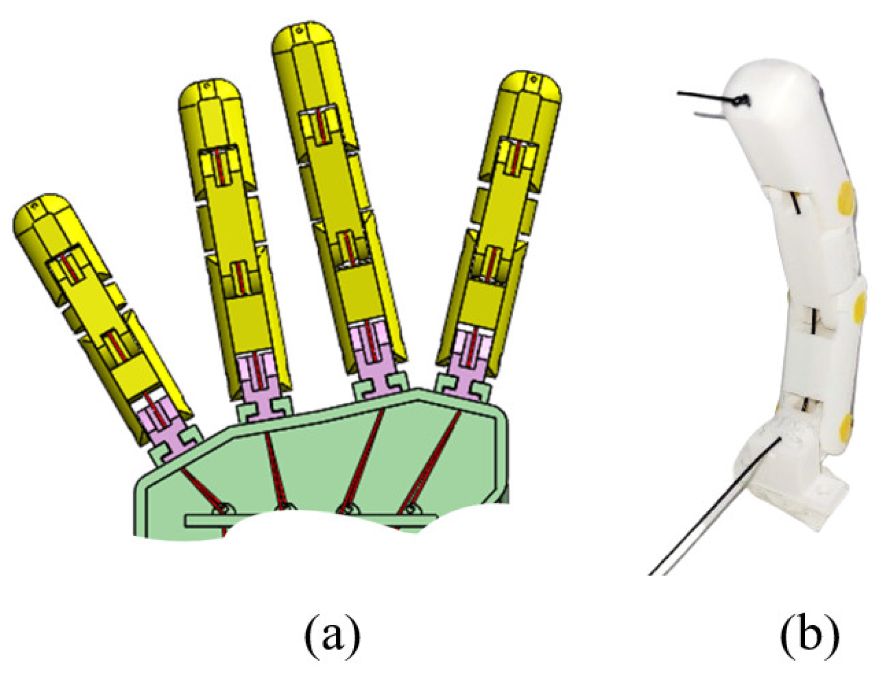
3.2. Prosthetic Hand Design

A complete prosthetic hand has been developed to perform grasping experiments to check the validity of the novel palmar configuration. The design involves fingers oriented at angles (Table 4) and placed at locations (Table 5) per the values obtained in the previous section. This subsection presents the fingers and the motion transmission mechanism used in the prosthetic hand.
Since the objective here is to test the finger configuration, primitive tendon-driven fingers are used in the prosthetic hand design owing to their simplicity. Each finger has three anthropomorphic segments controlled by a single flexor tendon. Each finger has an extension spring to assist finger extension motion without external actuation, as suggested in [39]. The 3D CAD model and the 3D printed prototype of the fingers used in the prosthetic hand are shown in Figure 10.

3.2.1. Motion Transmission Mechanism

The performance of an underactuated prosthetic hand depends on how its actuators provide motion to the active joints. The degree of underactuation is determined by the number of actuators, and minimizing this number is crucial in prosthetic hand design. Fewer actuators offer several advantages: (i) reduced weight, (ii) lower battery requirements for extended use, (iii) simplified control architecture with fewer biosignal inputs, and (iv) reduced cost, as motors are the priciest components. However, fewer motors limit individual finger control and dexterity, influencing the design of the motion transmission system.
In the current work, a novel motion transmission mechanism (MTM) has been developed to control the prosthetic hand. Given the emphasis on the novel finger configuration analysis, it is essential to design an MTM capable of efficiently actuating the proposed prosthetic hand while maintaining its functional versatility and precision. The hand is chosen to be actuated by three input motors—one DC motor (N20 Motor, 12V, 60 RPM, 1.6 Nm of Rated Stall Torque) and two servo motors (Tower Pro SG90 with continuous rotation, 0.12 Nm of Stall Torque). The DC motor is used to actuate the flexion motion of all five fingers. The two servo motors individually control the Ab/Ad motion of the thumb. All three motors are placed in the forearm region of the designed hand. The single DC motor input is distributed to the four fingers through a whippletree-based differential mechanism. A modified whippletree-based differential mechanism is used here for motion transmission to generate adaptive grasping. It is generally used in the design of prosthetic hands to provide uniform force output to the fingers [40,41]. The other advantage of using a Whippletree mechanism is that, when properly designed, it enables complete flexion of those fingers that do not contact the object being grasped. The input motion through the differential mechanism halts once all the fingers reach maximum flexion or have contacted the object. The overall motion transmission mechanism involving motors and the differential mechanism is shown in Figure 11.
The mechanism consists of three links (AB, CD, and EF), as shown in Figure 11b. It typically features symmetric links to distribute the input to all the outputs evenly. However, in this prosthetic hand design, the pivot points of the links are acentric. This acentricity is intended to create the stable 3-fingered tripod as the initial pose. Grasping studies show that most daily objects can be effectively manipulated using only a tripod grasp [21].
In the current design, the link lengths of the differential mechanism are set such that the fingers have anthropomorphic behavior. Link AB has an uneven fulcrum point with l 1 < l 2 . The index finger and the thumb make preliminary contact with the object. Hence, the mechanism should provide more space for the middle finger to flex, and hence l 1 < l 2 . By a similar logic, l 3 < l 4 and l 5 < l 6 for links 2 and 3, respectively. The ratio of link lengths— l 1 l 2 , l 3 l 4 , and l 5 l 6 —is decided based on the linear tendon excursion required to complete the entire ROM for each of the four fingers individually. Tendon excursion accounts for the fingertip’s Euclidean distance during motion and finger sizes. The excursion length, a , was measured experimentally for each finger using a prototype with a 3D-printed model actuated by a tendon connected to the distal phalanx. a represents the length needed for full flexion. The link length ratios were then determined as in Equation (7).
l 1 l 2 = a i n d e x a m i d d l e l 3 l 4 = a l i t t l e a r i n g l 5 l 6 = a i n d e x + a l i t t l e a r i n g + a m i d d l e
Based on the above ratios, the values of the link lengths were obtained, as presented in Table 8.

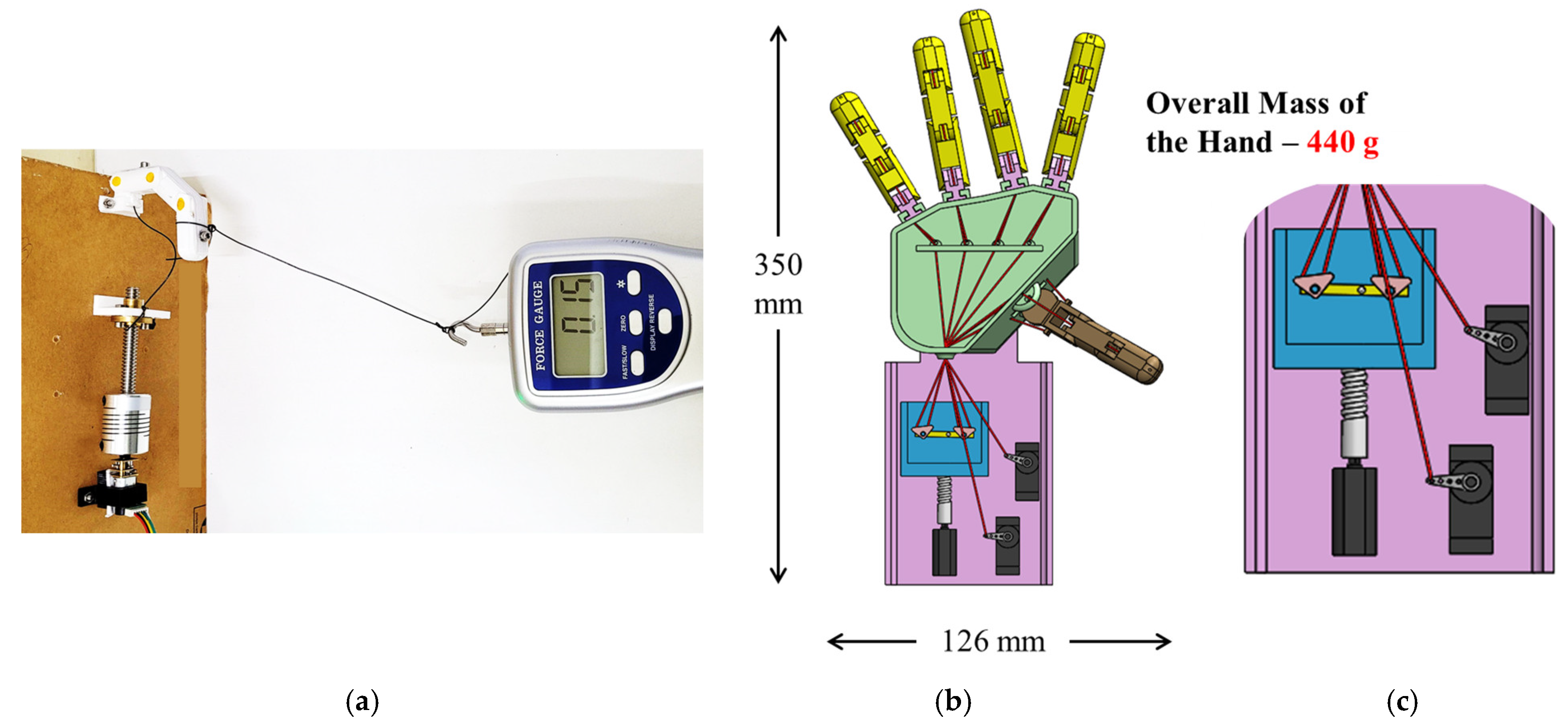
3.2.2. Prototyping and Experiments

Grasping experiments with the hand prototype were performed to validate the prosthetic hand design. A single finger was prototyped using the 3D printing technique as a first step in the experimentation. Polylactic acid (PLA) material was used in the 3D printing process because of its ease of printing. The individual finger prototype was experimentally flexed to calculate fingertip force production. It was observed that the single finger could produce ~1.5 N force when it was at the maximum flexed position. The experimental setup used to calculate the force is shown in Figure 12a.
The complete prosthetic hand was 3D printed with four 1-DoF fingers as per the design from the previous subsection. The prosthetic hand was designed to have a simplistic 3-DoF thumb only for experimental purposes. It is critical to note that the term “DoF” for the prototype has been used to indicate the kinematic configuration of the fingers and does not represent the number of independent axes of motion. As designed earlier, each finger is controlled by a singular tendon and hence has one degree of actuation for the three joints. The tendon-driven thumb has flexion capabilities at the MCP and PIP joints and Ab/Ad motion at the CMC joint. The CAD model of the hand prototype is shown in Figure 12b,c. The entire hand mechanism was mounted on a 5 mm acrylic sheet for experimental purposes. The 3D printed hand model and the objects that were used in the grasping experiment are shown in Figure 13. It was observed that the hand prototype was able to grasp the objects successfully. Further, because of the differential mechanism that has been implemented, the ring and little finger flex completely during three-fingered grasping, as shown in Figure 13e,f. The motors were controlled using a custom Arduino program loaded onto an Arduino UNO board. The experiments showed that the designed hand could successfully grasp objects of various shapes and sizes. The Supplementary Materials provides additional data about the prototype and experiments.

4. Discussion

A prosthetic hand must exhibit basic anthropomorphic behavior, as it needs to interact with objects designed, created, and used by the human hand [2]. The design of prosthetic hands involves inherent contradictions, demanding an optimal balance to meet diverse requirements. Table 9 below provides a comparison of some of the prosthetic hands available in the literature.
Two main conclusions can be drawn from the above table despite its non-exhaustive nature—(i) prosthetic hands having 2-DoF MCP joints with active Ab/Ad motion involve complexity in mechanism or actuators or both, (ii) the majority of prosthetic hands available in the literature have parallel finger arrangement with reduced dexterity. This work addresses these challenges by presenting a novel design paradigm for underactuated prosthetic hands. This methodology leads to novel bio-inspired finger configurations for the index, middle, ring, and little fingers. The configuration consists of two key elements: finger orientation and finger placement. The novel finger orientation reduces the number of controlled joints by eliminating the need for an active MCP Ab/Ad joint, simplifying the overall hand design. This innovative approach allows the hand to grasp objects of various sizes and shapes without sacrificing dexterity. Additionally, finger inclination can be customized for specific tasks or postures, increasing versatility. Further, a new finger placement is introduced to improve dexterity in the three DoF fingers in the current work. The positioning of the finger bases is undertaken to match anthropomorphic behavior.
Grasp simulation results show that the current configuration outperforms conventional parallel finger design. A preliminary prosthetic hand prototype was designed, 3D-printed, and validated using a tendon-driven mechanism and a novel whippletree-based differential mechanism-based motion transmission system. The novel differential mechanism’s lever lengths were calculated and optimized using experimental tendon excursions and anthropometric data.
The authors emphasize that alternative inclination angles, derived from various performance indices, can enhance grasping capabilities beyond those of traditional prosthetic hands with parallel fingers. Rather than determining the optimal inclination angles, this paper demonstrates that the proposed methodology significantly improves grasping performance. However, it is also possible for some of the derived orientations to be non-ergonomic, leading to intersecting finger trajectories. Even in the current work, based on the PIs selected, we have obtained inclinations of 13° and 10° for the middle and ring finger, respectively. This orientation may lead to the two fingers intersecting while grasping small objects, which is a drawback of the current design. Further, the current prototype built for the grasp experiment is primitive. Hence, a thorough integration of stability-based design must be performed for the prosthetic hand. Additionally, all the electronics, motors, and accessories must be optimally positioned to help develop a complete prosthetic hand.
The current work does not focus on the kinematic analysis or configuration of the thumb due to its complexity. A basic thumb design is only included in the prototype solely for grasping experiments. However, as the thumb is crucial for effective grasping, as highlighted earlier, a dedicated thumb analysis will be conducted in future work to develop a fully functional prosthetic hand. Further, a finger mechanism capable of producing sufficient force output at the fingertips must be developed to enable the prosthetic hand to grasp various objects efficiently. Finally, an MTM capable of actuating the fingers individually needs to be designed to have refined movements and enhanced dexterity of the prosthetic hand.

5. Conclusions

A novel design paradigm for achieving dexterous finger configuration for the index, middle, ring, and little fingers has been presented in this work. The finger orientation and placements have an anatomical and physiological basis, enabling the prosthetic hand to grasp objects of various shapes and sizes. The grasping performance of the proposed hand is compared with that of a human hand and a prosthetic hand with parallel fingers through simulation. It was observed from the simulated results involving grasp quality measures that the performance of the current hand was better than the parallel finger design for prosthetic hands.
A preliminary prosthetic hand has been designed, developed, and 3D printed to validate the design. A primitive design for fingers involving tendon-driven fingers was used in the current work for validation purposes. The hand was also designed to transmit input motion through a novel whippletree-based differential mechanism. The novelty of the current MTM is that the lever lengths of the differential mechanism have been calculated based on experimental tendon excursions and anthropometric parameters. As a final step in the work, the 3D printed prototype was used to grasp real-world objects in a static setting. The hand prototype successfully grasped objects of various sizes and shapes, validating the current finger orientation.

Supplementary Materials

The following supporting information can be downloaded at: https://www.mdpi.com/article/10.3390/app15063214/s1, Video S1: MCP Analysis.mp4.

Author Contributions

Conceptualization, V.S. (Vignesh Sompur), V.S. (Varadhan SKM) and A.T.; Formal analysis, V.S. (Vignesh Sompur); Methodology, V.S. (Vignesh Sompur); Supervision, V.S. (Varadhan SKM) and A.T.; Visualization, V.S. (Vignesh Sompur); Writing—original draft, V.S. (Vignesh Sompur); Writing—review and editing, V.S. (Varadhan SKM) and A.T. All authors have read and agreed to the published version of the manuscript.

Funding

This research received no external funding.

Institutional Review Board Statement

The study was conducted in accordance with the Declaration of Helsinki. The kinematic data collection experiment performed as a part of this work was approved by the institutional ethics committee at IIT Madras (IEC/2020-03/SKM/02/10).

Informed Consent Statement

Informed consent was obtained from all subjects involved in the study.

Data Availability Statement

The original contributions presented in the study are included in the article/Supplementary Materials. Further inquiries can be directed to the corresponding author.

Acknowledgments

The authors would like to sincerely thank Prajwal Shenoy for his contribution during the kinematic data collection phase of the current work.

Conflicts of Interest

The authors declare no conflicts of interest.

Abbreviations

The following abbreviations are used in this manuscript:
Ab/AdAbduction/Adduction
ADLActivities of Daily Living
CADComputer-Aided Design
CMCCarpometacarpal
DHDenavit–Hartenberg
DIPDistal Interphalangeal
DoFDegree of Freedom
EMGElectromyography
F/EFlexion/Extension
MCPMetacarpophalangeal
MTMMotion Transmission Mechanism
PCAPrincipal Component Analysis
PIPerformance Index
PIPProximal Interphalangeal
PLAPoly-Lactic Acid
ROMRange of Motion
SDStandard Deviation

Appendix A

Appendix A.1. Kinematic Data Collection Experiment—Setup

The participants were asked to sit comfortably on a height-adjustable wooden chair before a table. A monitor screen was placed in front of the participant at a distance of 1.5 m, as shown in Figure A1. The posture that the participant needed to perform was displayed on the monitor as a reference. Since Polhemus EMTS is highly susceptible to magnetic distortion, care was taken to eliminate all metal parts within a 2 m radius of the participant. Orientation and position data were collected from each sensor. The sensors provided the data with reference to the source box. The collected data were appropriately transformed to the wrist frame of reference using transformation matrices. The position for each sensor and angle for each joint was then computed using relative transformations.
Figure A1. Experimental setup for kinematic data collection.
Applsci 15 03214 g0a1

References

  1. Ingram, J.N.; Körding, K.P.; Howard, I.S.; Wolpert, D.M. The statistics of natural hand movements. Exp. Brain Res. 2008, 188, 223–236. [Google Scholar] [CrossRef] [PubMed]
  2. Balasubramanian, R.; Santos, V.J. (Eds.) The Human Hand as an Inspiration for Robot Hand Development; Springer Tracts in Advanced Robotics; Springer International Publishing: Cham, Switzerland, 2014; Volume 95. [Google Scholar] [CrossRef]
  3. Meghdari, A.; Arefi, M.; Mahmoudian, M. Geometric adaptability: A novel mechanical design in the Sharif artificial hand. Int. J. Robot. Autom. 1992, 7, 80–85. [Google Scholar]
  4. Crowder, R.M. An anthropomorphic robotic end effector. Robot. Auton. Syst. 1991, 7, 253–268. [Google Scholar] [CrossRef]
  5. Mouri, T.; Kawasaki, H.; Yoshikawa, K.; Takai, J.; Ito, S. Anthropomorphic robot hand: Gifu hand III. In Proceedings of the International Conference (ICCAS 2002), Muju Resort, Republic of Korea, 16–19 October 2002; pp. 1288–1293. [Google Scholar]
  6. Mendez, V.; Iberite, F.; Shokur, S.; Micera, S. Current Solutions and Future Trends for Robotic Prosthetic Hands. Annu. Rev. Control. Robot. Auton. Syst. 2021, 4, 595–627. [Google Scholar] [CrossRef]
  7. Cordella, F.; Ciancio, A.L.; Sacchetti, R.; Davalli, A.; Cutti, A.G.; Guglielmelli, E.; Zollo, L. Literature review on needs of upper limb prosthesis users. Front. Neurosci. 2016, 10, 209. [Google Scholar] [CrossRef]
  8. Jarque-Bou, N.J.; Vergara, M.; Sancho-Bru, J.L.; Gracia-Ibáñez, V.; Roda-Sales, A. Hand kinematics characterization while performing activities of daily living through kinematics reduction. IEEE Trans. Neural Syst. Rehabil. Eng. 2020, 28, 1556–1565. [Google Scholar] [CrossRef]
  9. Gentile, C.; Cordella, F.; Zollo, L. Hierarchical Human-Inspired Control Strategies for Prosthetic Hands. Sensors 2022, 22, 2521. [Google Scholar] [CrossRef]
  10. Piazza, C.; Grioli, G.; Catalano, M.G.; Bicchi, A. A Century of Robotic Hands. Annu. Rev. Control Robot. Auton. Syst. 2019, 2, 1–32. [Google Scholar] [CrossRef]
  11. Kandel, E.R.; Schwartz, J.H.; Jessell, T.M.; Siegelbaum, S.A.; Hudspeth, A.J. Principles of Neural Science, 5th ed.; McGraw Hill Professional: New York, NY, USA, 2013. [Google Scholar]
  12. Napier, J.R.; Tuttle, R.H. Hands; Princeton University Press: Princeton, NJ, USA, 1993. [Google Scholar]
  13. van der Hulst, F.P.J.; Schatzle, S.; Preusche, C.; Schiele, A. A functional anatomy based kinematic human hand model with simple size adaptation. In Proceedings of the 2012 IEEE International Conference on Robotics and Automation, St Paul, MN, USA, 14–18 May 2012; pp. 5123–5129. [Google Scholar] [CrossRef]
  14. MacKenzie, C.L.; Iberall, T. The Grasping Hand; Elsevier: Amsterdam, The Netherlands, 1994. [Google Scholar]
  15. Cobos, S.; Ferre, M.; Aracil, R. Simplified human hand models based on grasping analysis. In Proceedings of the 2010 IEEE/RSJ International Conference on Intelligent Robots and Systems, Taipei, Taiwan, 1 October 2010; pp. 610–615. [Google Scholar] [CrossRef]
  16. Demers, L.-A.A.; Gosselin, C. Kinematic design of a planar and spherical mechanism for the abduction of the fingers of an anthropomorphic robotic Hand. In Proceedings of the 2011 IEEE International Conference on Robotics and Automation, Shanghai, China, 9–13 May 2011; pp. 5350–5356. [Google Scholar] [CrossRef]
  17. Kontoudis, G.P.; Liarokapis, M.; Vamvoudakis, K.G.; Furukawa, T. An Adaptive Actuation Mechanism for Anthropomorphic Robot Hands. Front. Robot. AI 2019, 6, 47. [Google Scholar] [CrossRef]
  18. Cerruti, G.; Chablat, D.; Gouaillier, D.; Sakka, S. Design method for an anthropomorphic hand able to gesture and grasp. In Proceedings of the 2015 IEEE International Conference on Robotics and Automation (ICRA), Seattle, WA, USA, 26–30 May 2015; pp. 3660–3667. [Google Scholar] [CrossRef]
  19. Yan, Y.; Chen, X.; Cheng, C.; Wang, Y. Design, kinematic modeling and evaluation of a novel soft prosthetic hand with abduction joints. Med. Nov. Technol. Devices 2022, 15, 100151. [Google Scholar] [CrossRef]
  20. Halim, A. Human Anatomy: Volume I: Upper Limb and Thorax; I. K. International Pvt Ltd.: New Delhi, India, 2008. [Google Scholar]
  21. The GRASP Taxonomy of Human Grasp Types | IEEE Journals & Magazine | IEEE Xplore. Available online: https://ieeexplore.ieee.org/abstract/document/7243327 (accessed on 11 March 2024).
  22. Shenoy, P.; Sompur, V.; Skm, V. Methods for Measurement and Analysis of Full Hand Angular Kinematics Using Electromagnetic Tracking Sensors. IEEE Access 2022, 10, 42673–42689. [Google Scholar] [CrossRef]
  23. Hamilton, W.R. Elements of Quaternions; Longmans, Green, & Company: London, UK, 1866. [Google Scholar]
  24. Santello, M.; Flanders, M.; Soechting, J.F. Postural Hand Synergies for Tool Use. J. Neurosci. 1998, 18, 10105–10115. [Google Scholar] [CrossRef] [PubMed]
  25. Peña-Pitarch, E.; Falguera, N.T.; Yang, J. Virtual human hand: Model and kinematics. Comput. Methods Biomech. Biomed. Eng. 2014, 17, 568–579. [Google Scholar] [CrossRef] [PubMed]
  26. Yang, W.; Wu, X.; Zhang, H. Workspace Modeling and Analysis for Dexterous Hands. Int. J. Human. Robot. 2015, 12, 1550006. [Google Scholar] [CrossRef]
  27. Yang, W.; Xuan, J.; Wu, X.; Lian, C.; Pan, Z. A Workspace Modeling Approach for Multi-finger Hands. In Proceedings of the 2016 International Conference on Cyberworlds (CW), Chongqing, China, 28–30 September 2016; pp. 104–110. [Google Scholar] [CrossRef]
  28. Russo, M. Measuring performance: Metrics for manipulator design, control, and optimization. Robotics 2022, 12, 4. [Google Scholar] [CrossRef]
  29. Yoshikawa, T. Manipulability of Robotic Mechanisms. Int. J. Robot. Res. 1985, 4, 3–9. [Google Scholar] [CrossRef]
  30. Llop-Harillo, I.; Pérez-González, A.; Andrés-Esperanza, J. Anthropomorphism Indexes of the Kinematic Chain for Artificial Hands. J. Bionic Eng. 2020, 17, 501–511. [Google Scholar] [CrossRef]
  31. Kapandji, A. Clinical test of apposition and counter-apposition of the thumb. Ann. Chir. Main 1986, 5, 67–73. [Google Scholar] [CrossRef]
  32. Biagiotti, L.; Lotti, F.; Melchiorri, C.; Vassura, G. How Far Is the Human Hand. A Review on Anthropomorphic Robotic End-Effectors; University of Bologna: Bologna, Italy, 2004. [Google Scholar]
  33. Liu, Y.; Yang, D.; Jiang, L.; Liu, H. A synthetic framework for evaluating the anthropomorphic characteristics of prosthetic hands. In Proceedings of the 2015 IEEE International Conference on Advanced Intelligent Mechatronics (AIM), Busan, Republic of Korea, 7–11 July 2015; pp. 877–884. [Google Scholar] [CrossRef]
  34. Feix, T.; Romero, J.; Ek, C.H.; Schmiedmayer, H.-B.; Kragic, D. A Metric for Comparing the Anthropomorphic Motion Capability of Artificial Hands. IEEE Trans. Robot. 2012, 29, 82–93. [Google Scholar] [CrossRef]
  35. Liarokapis, M.V.; Artemiadis, P.K.; Kyriakopoulos, K.J. Quantifying anthropomorphism of robot hands. In Proceedings of the 2013 IEEE International Conference on Robotics and Automation, Karlsruhe, Germany, 6–10 May 2013; pp. 2041–2046. [Google Scholar] [CrossRef]
  36. Malvezzi, M.; Gioioso, G.; Salvietti, G.; Prattichizzo, D. Syngrasp: A matlab toolbox for underactuated and compliant hands. IEEE Robot. Autom. Mag. 2015, 22, 52–68. [Google Scholar] [CrossRef]
  37. Roa, M.A.; Suárez, R. Grasp quality measures: Review and performance. Auton. Robot. 2015, 38, 65–88. [Google Scholar] [CrossRef]
  38. Banuvathy, R.; Varadhan, S.K.M. Distinct behavior of the little finger during the vertical translation of an unsteady thumb platform while grasping. Sci. Rep. 2021, 11, 21064. [Google Scholar] [CrossRef]
  39. Birglen, L.; Laliberté, T.; Gosselin, C. Underactuated Robotic Hands; Springer Tracts in Advanced Robotics; Springer: Berlin/Heidelberg, Germany, 2008; Volume 40. [Google Scholar] [CrossRef]
  40. Fukaya, N.; Toyama, S.; Asfour, T.; Dillmann, R. Design of the TUAT/Karlsruhe humanoid hand. In Proceedings of the 2000 IEEE/RSJ International Conference on Intelligent Robots and Systems (IROS 2000) (Cat. No. 00CH37113), Takamatsu, Japan, 31 October–5 November 2000; pp. 1754–1759. [Google Scholar]
  41. Kumarage, K.P.L.; Wickramarathan, W.H.S.; Madhushan, V.; Mugilgeethan, V.; Neethan, R.; Thanihaichelvan, T. A Novel 3 -D Printed Wrist Powered Upper Limb Prosthesis Using Whippletree Mechanism. 2019. Available online: http://repo.lib.jfn.ac.lk/ujrr/handle/123456789/8647 (accessed on 5 February 2024).
  42. Yang, H.; Tao, Z.; Yang, J.; Ma, W.; Zhang, H.; Xu, M.; Wu, M.; Sun, S.; Jin, H.; Li, W.; et al. A lightweight prosthetic hand with 19-DOF dexterity and human-level functions. Nat. Commun. 2025, 16, 955. [Google Scholar] [CrossRef] [PubMed]
  43. You, W.S.; Lee, Y.H.; Oh, H.S.; Kang, G.; Choi, H.R. Design of a 3D-printable, robust anthropomorphic robot hand including intermetacarpal joints. Intell. Serv. Robot. 2019, 12, 1–16. [Google Scholar] [CrossRef]
  44. Gollob, S.D.; Poss, J.; Memoli, G.; Roche, E.T. A Multi-Material, Anthropomorphic Metacarpophalangeal Joint with Abduction and Adduction Actuated by Soft Artificial Muscles. IEEE Robot. Autom. Lett. 2022, 7, 5882–5887. [Google Scholar] [CrossRef]
  45. Zhang, T.; Jiang, L.; Liu, H. Design and Functional Evaluation of a Dexterous Myoelectric Hand Prosthesis with Biomimetic Tactile Sensor. IEEE Trans. Neural Syst. Rehabil. Eng. 2018, 26, 1391–1399. [Google Scholar] [CrossRef]
  46. Controzzi, M.; Clemente, F.; Barone, D.; Ghionzoli, A.; Cipriani, C. The SSSA-MyHand: A Dexterous Lightweight Myoelectric Hand Prosthesis. IEEE Trans. Neural Syst. Rehabil. Eng. 2016, 25, 459–468. [Google Scholar] [CrossRef]
  47. Jeong, S.H.; Kim, K.-S.; Kim, S. Designing Anthropomorphic Robot Hand with Active Dual-Mode Twisted String Actuation Mechanism and Tiny Tension Sensors. IEEE Robot. Autom. Lett. 2017, 2, 1571–1578. [Google Scholar] [CrossRef]
  48. Weiner, P.; Starke, J.; Hundhausen, F.; Beil, J.; Asfour, T. The KIT Prosthetic Hand: Design and Control. In Proceedings of the 2018 IEEE/RSJ International Conference on Intelligent Robots and Systems (IROS), Madrid, Spain, 1–5 October 2018; pp. 3328–3334. [Google Scholar] [CrossRef]
Figure 1. (a) The joints of the human hand. (b) Kinematic model of the human hand showing the DoF for all the joints of each finger.
Applsci 15 03214 g001
Figure 2. (a) Postures and objects used in the kinematic data collection experiment involving human participants. (b) Polhemus Microsensor. (c) Sensor placement locations on the dorsal surface of the hand.
Applsci 15 03214 g002
Figure 3. (a) Cumulative variance of all the principal components of the combined dataset. (b) Loading plot to indicate the relative importance of the 4 angles of the index finger in the first 2 principal components.
Applsci 15 03214 g003
Figure 4. The coefficient of variance for the MCP F/E and Ab/Ad angles of normalized data for all 4 fingers.
Applsci 15 03214 g004
Figure 5. Kinematic diagram indicating the link lengths and orientation.
Applsci 15 03214 g005
Figure 6. Plot showing fingertip workspace of index, middle, ring, and little fingers in three-dimensional space.
Applsci 15 03214 g006
Figure 7. Flowchart indicating overall methodology employed in calculating performance indices for the design of the prosthetic hand.
Applsci 15 03214 g007
Figure 8. The variation of manipulability index across the ROM of MCP Ab/Ad joint for (a) index finger, (b) middle finger, (c) ring finger, (d) little finger.
Applsci 15 03214 g008
Figure 9. Location of finger bases on the palmar surface.
Applsci 15 03214 g009
Figure 10. (a) CAD model of the fingers also showing the finger orientation, (b) 3D printed prototype of the finger used in the prosthetic hand.
Applsci 15 03214 g010
Figure 11. (a) Schematic diagram showing the motion transmission mechanism designed for controlling the prosthetic hand using 3 input motors. (b) Whippletree-based differential mechanism used for uniform force distribution among the 4 fingers.
Applsci 15 03214 g011
Figure 12. (a) Experimental setup for fingertip force measurement of 3D printed finger using force gauge. (b) Complete CAD model for the hand assembly. (c) Enlarged view of the differential mechanism and the motor assembly.
Applsci 15 03214 g012
Figure 13. (a,b) Complete setup of the 3D printed prototype with finger in its extended position. (cf) Grasping various objects using the hand prototype.
Applsci 15 03214 g013
Table 1. DH parameters for index, middle, ring, and little fingers.
Joint No. θ i (rad) a i (mm) d i (mm) α i (rad)
1 θ i 1 (MCP Ab/Ad)00 π 2
2 θ i 2 (MCP F/E) l i 2 00
3 θ i 3 (PIP F/E) l i 3 00
4 θ i 4 (DIP F/E) l i 4 00
Table 2. ROM for index, middle, ring, and little fingers.
MCP Ab/Ad (deg)MCP F/E (deg)PIP F/E (deg)DIP F/E (deg)
Index35/−1590/0100/090/0
Middle15/−1590/0100/090/0
Ring−20/1590/0100/090/0
Little−35/1090/0100/090/0
Table 3. Length parameters for all the five fingers of the hand.
Index
(mm)
Middle
(mm)
Ring
(mm)
Little
(mm)
l I 2 = 40 l I I 2 = 45 l I I I 2 = 42 l I V 2 = 32
l I 3 = 23 l I I 3 = 25 l I I I 3 = 24 l I V 3 = 19
l I 4 = 15 l I I 4 = 19 l I I I 4 = 17 l I V 4 = 12
Table 4. Value of Ab/Ad angle based on thumb opposability index.
FingerIndexMiddleRingLittle
Ab/Ad Angle13°−13°−10°−30°
Table 5. Coordinates of the finger bases.
PointCoordinate (mm)PointCoordinate (mm)
G ( 0 , 0 ) O3 ( 10 , 80 )
O1 ( 10 , 16.91 ) O4 ( 10 , 68.45 )
O2 ( 30 , 73 ) O5 ( 30 , 56.91 )
Table 6. Simulation results indicating volume of manipulability ellipsoid.
Objects Human   Hand   ( m m 3 ) Parallel Finger Design
( m m 3 )
Current Design
( m m 3 )
ϕ 50 mm Sphere109.351.866.9
ϕ 70 mm Sphere2066.977.71950.3
ϕ 100 mm Sphere236.285.5216.7
ϕ 40 mm; h = 100 mm Cylinder10.55.56.5
ϕ 60 mm; h = 120 mm Cylinder208.215.550.1
30 mm side Cube43.932.334.1
Table 7. Result of finger interactivity index for human hand, prosthetic hand with parallel fingers, and current design.
Human HandParallel Finger DesignCurrent Design
IF7.74.75.9
Table 8. Link lengths of the differential mechanism.
LinkLength (mm)LinkLength (mm)LinkLength (mm)
l 1 6 l 3 5 l 5 12
l 2 8 l 4 8 l 6 16
Table 9. Comparison of prosthetic hands available in the literature.
ReferenceMCP Joint DoFActive Ab/AdFinger ArrangementActuation MechanismKey Features
[42]2YesNon-Parallel (Random)Shape memory alloys with wires19-DoF biomimetic hand with 38 shape memory alloys for control.
[43]2YesNon-Parallel (Random)Hybrid—Tendons, ball screw, and movable pulleysThe SKKU hand has 14 DoF across only four fingers. The MCP joint has a decoupled mechanism for separate control of F/E and Ab/Ad motions.
[44]2YesSingle finger designedMcKibben soft actuatorsA single finger‘s biomimetic structure, control, and anthropomorphic motion are achieved through artificial muscles.
[17]2YesParallel (default)Bilateral tendonsThe hand consists of soft fingers capable of simultaneous F/E and Ab/Ad motion through selective actuation of tendons.
[45]1NoParallel ArrangementIndividual DC motors6-DoF myoelectric hand with modular fingers with motors mounted inside the finger body.
[46]1NoNon-ParallelDC motors with Geneva driveThis 5-fingered hand has index, middle, ring, and little fingers evenly spaced at 10 ° . Index and thumb motions are coupled.
[47]1NoNot Available Twisted string actuation6-DoF hand.
10 motors to provide all the inputs.
[48]1NoParallelTendons10-DoF KIT Prosthetic hand has two motors to control and 3 segmented fingers.
Current Work1NoNon-Parallel (Specific)TendonsFingers oriented at specific angles based on performance indices for optimal grasping capabilities.
Disclaimer/Publisher’s Note: The statements, opinions and data contained in all publications are solely those of the individual author(s) and contributor(s) and not of MDPI and/or the editor(s). MDPI and/or the editor(s) disclaim responsibility for any injury to people or property resulting from any ideas, methods, instructions or products referred to in the content.

