Featured Application
This study’s findings have direct applications in the design and optimization of aircraft brake systems, enhancing the understanding of heat transfer behaviors in brake discs.
Abstract
Aircraft brake discs undergo rapid temperature rises during braking, critically impacting safety, lifespan, and adjacent components. Therefore, it is particularly important to study the heat transfer mechanism during the braking process and predict the temperature distribution of the brake disc. To address challenges in experimental studies (e.g., high costs and extreme conditions), this study employs full-scale numerical simulations to investigate heat transfer behaviours in medium-sized passenger aircraft brake discs. In the numerical simulation process, a coupling model that comprehensively considers the friction heat generation of the brake disc, the solid heat transfer between the discs, and the heat dissipation of the outer surface of the disc and the surrounding air is constructed to accurately describe the heat transfer characteristics of the brake disc under dynamic conditions. The study shows that the surface temperature of the brake disc rises sharply during the braking process, resulting in a significant increase in the temperature gradient; at the same time, the surrounding air flow state significantly affects the heat dissipation efficiency of the brake disc and affects its temperature distribution. Finally, the effectiveness of the numerical simulation was verified by experiments, and the maximum relative error between the experimental results and the simulation results was about 4.5%. This study provides a research basis for optimizing the structural design of the brake disc, improving its heat dissipation performance and operating safety.
1. Introduction
The brake disc is a crucial component of mechanical braking systems, responsible for rapidly converting kinetic energy into thermal energy through friction, thereby enabling the deceleration or stopping of vehicles or equipment. Its performance is vital to ensuring operational safety and stability [1]. In aircraft braking systems, the brake disc operates under more demanding conditions compared to ground transportation. During landing and taxiing, the disc must endure significant energy conversions, leading to a rapid temperature rise on its surface and generating complex temperature fields and thermal stress distributions [2].
To meet the high-intensity braking requirements, aircraft brake discs are typically made from carbon-based composite materials, known for their exceptional lightweight and high-temperature resistance properties [3]. However, thermal stress accumulation under high-temperature conditions can result in cracking, deformation, or material failure, potentially impacting the functionality of adjacent components and threatening the aircraft’s operational safety. Thus, accurately predicting the temperature distribution in brake discs is critical for optimizing structural design and material selection, extending service life, and ensuring operational reliability and safety.
Current research on disc brakes for automobiles and trains is abundant [4,5,6,7], but studies on the temperature field of aircraft brake discs remain relatively limited. Kennedy et al. [8] pioneered the use of finite element methods to analyze the unsteady thermoelastic problem in aircraft braking systems and proposed a criterion for predicting wear rates of disc brakes in 1974. Qi et al. [9] employed thermocouples to measure the temperature at the friction interface and investigated its distribution patterns. Grzes [10] introduced a method based on HDFW equations to calculate the maximum temperature on the friction surface during braking. However, these studies largely rely on experimental testing and simplified theoretical analyses, constrained by time, cost, and the complexity of boundary conditions.
In order to verify the thermal safety of the brakes during the design phase, a computational model capable of predicting their thermal behaviour is required. Nosko et al. [11] established a model considering the heat exchange with the environment, derived formulas, and verified them through experiments, providing theoretical support and a basis for the calculation of the thermal analysis of aircraft brakes. With advancements in computational technology, numerical simulation has emerged as a vital tool for investigating heat transfer problems in brake discs. Constructing heat transfer models enables effective analysis of temperature distributions and their variations under different working conditions. Lei et al. [12] simulated the transient temperature field of carbon–carbon (C/C) composite aircraft brake discs, and clarified the calculation method of thermal load and the determination method of key parameters. By combining experiments and simulations, a real temperature field distribution nephogram was obtained. However, in this study, only 1/8 of the brake disc was used for 3D solid modelling, so there are still differences in the full-scale heat transfer characteristics. The interfacial heat transfer characteristics of C/C composite and the frictional heat generation process are necessary conditions for high-precision numerical simulation. Peszynska-Bialczyk et al. [13] used techniques such as Thermogravimetric Analysis/Fourier Transform Infrared Spectroscopy (TGA/FTIR), Temperature-Programmed Reduction (TPR), and Pyrolysis–Gas Chromatography–Mass Spectrometry (Py–GC–MS) to study the thermal behaviour and surface changes of C/C composites during simulated aircraft braking, providing a basis for a deeper understanding of the performance of this material in braking applications. Bauzin et al. [14] simulated the aircraft braking process by building an experimental platform, measured the system temperature, and used a one-dimensional thermal model and inverse method to identify the frictional heat flux, providing an important basis for research on the thermal performance of aircraft braking systems. This method relies on experimental data for parameter setting. However, how to set parameters during the brake design stage remains to be explored. Meanwhile, most studies are confined to specific scales or idealized conditions, with limited research on full-scale simulations under diverse conditions. This is particularly true for medium-sized aircraft brake discs (e.g., 100-seat, 50-ton class), where related research remains insufficient.
This study focuses on medium-sized aircraft brake discs, conducting full-scale numerical simulations to investigate their heat transfer characteristics during braking, with the aim to analyze the thermal performance of the braking system during design phase. A multiphysics coupling model was developed, accounting for key heat transfer mechanisms such as frictional heat generation, inter-disc thermal conduction, and surface heat dissipation via convection and radiation. The steps of parameter setting are described in detail. The model comprehensively captures the generation, transfer, and dissipation of heat under dynamic conditions, revealing the spatiotemporal distribution of the temperature field and the influence of varying operating conditions on heat transfer characteristics. Simulation results enable the accurate prediction of temperature distributions and the evaluation of the thermal load’s potential impact on the disc and surrounding components in the design phase. This research provides scientific insights for optimizing brake disc design, enhancing heat dissipation performance, and ensuring braking system reliability, contributing significantly to the operational safety and performance of medium-sized aircraft.
2. Model Description
2.1. Full-Size Brake Disc Geometry Mode
The multi-disc brake device of a medium-sized passenger aircraft includes a static brake disc, a dynamic brake disc, a torque tube, a brake actuator, and a brake wear indicator pin. The brake disc is composed of multiple static brake discs and dynamic brake discs, and the static discs and dynamic discs are stacked crosswise. The stator discs are shown in Figure 1a. They are installed onto the torque tube of the brake device, which are fixed relative to the landing gear, through an internal spline. It will not rotate with the wheel and can only move axially. The rotor discs are shown in Figure 1b. It is connected to the wheel hub through an external spline and can rotate with the wheel and move axially. When braking, the dynamic and static discs slide along the spline sleeve of the wheel hub and the spline shaft of the torque tube, respectively, so that the dynamic and static discs are pressed against each other to generate friction torque.
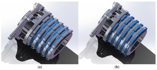
Figure 1.
Aircraft multi-disc brake system: (a) stator discs (blue part); (b) rotor discs (blue part).
The brake disc consists of five rotor discs and four stator discs stacked crosswise, and some structural parameters are listed in Table 1. Braking causes the temperature of the brake disc to change, which may affect the material properties, structure, braking state, and other aspects of the brake disc. The brake disc material is carbon–carbon (C/C) material. The density of C/C composite materials is relatively low and does not significantly change with temperature. As the temperature increases, the specific heat capacity of C/C composite materials will gradually increase. The thermal conductivity may slightly increase with temperature at lower temperatures, but it may tend to stabilize or slightly decrease near 1000 °C. Under ultra-high temperature conditions, the constant value assumption may underestimate the material’s heat capacity and thermal conductivity, leading to inaccurate predictions of temperature distribution, especially in areas with large temperature gradients. The temperature range predicted in this paper is within 1000 °C, and the impact will be slightly smaller. In order to simplify the simulation of the actual braking process, it is assumed that the material physical property parameters are fixed values. The specific parameters are shown in Table 2.

Table 1.
Structural parameters of brake discs.
Table 2.
Thermophysical parameters of brake discs.
2.2. Braking Condition Analysis
Under braking conditions, the variation in wheel speed over time is shown in Figure 2, and the corresponding parameter values are listed in Table 3.
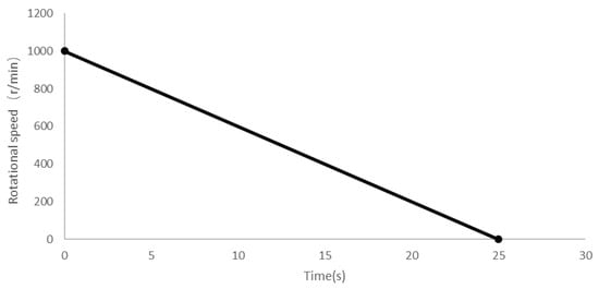
Figure 2.
The curve of wheel speed variation with time during the braking process.
Table 3.
Some parameters of aircrafts under braking conditions.
As shown in Table 3, the aircraft begins emergency braking at an initial speed of v0 = 36.7 m/s, relying solely on the disc braking system. With a constant deceleration of α = −1.468 m/s2, the braking duration is 25 s. The relationship between the aircraft’s speed vt and time t during braking is as follows:
During the braking the process of an aircraft, the brake disc decelerates along with the aircraft, and the law of the angular velocity of the brake disc changing with time is as follows:
where is the angular velocity; is the radius of the aircraft wheel. The change law of angular velocity will be used as the boundary condition to define the brake disc rotation speed in the brake disc coupling model.
During the braking process, the heat flux density generated is calculated using the following formula. The heat flux density changing with time is shown in Table 4.
Table 4.
The heat flux density changing with time.
3. Simulation Model and Simulation Methods
3.1. Finite Element Model
Based on the actual dimensions of the aircraft brake disc, a full-scale 1:1 three-dimensional model was created in SolidWorks v2021. The model consists of five rotating discs and four stationary discs stacked alternately, ensuring high detail fidelity and dimensional accuracy. During the braking process, the rotational structure of the brake discs disturbs the airflow within the limited volume. Therefore, a simplified model using a rectangular fluid domain as a virtual wind tunnel was adopted. The length of the rectangular fluid domain is approximately 2.6 times the outer diameter of the brake disc, measuring 900 mm; the height is approximately 1.8 times the outer diameter, measuring 600 mm; and the width is 540 mm. The right side of the rectangular domain serves as the air inlet, and the left side as the air outlet.
To visually observe the airflow disturbance caused by the brake disc, a cylindrical fluid domain with a diameter of 400 mm was created around the brake disc. To analyze the flow field behind the brake disc, the disc was positioned at one-quarter of the length of the fluid domain. The centre height of the brake disc was set to 300 mm, matching the sum of the aircraft wheel radius and the rail surface height, and the disc was placed in the centre of the width direction. Different fluid and solid domains were then defined, completing the construction of the brake disc computational model. The full-scale finite element model of the brake disc and the cylindrical fluid domain are shown in Figure 3.
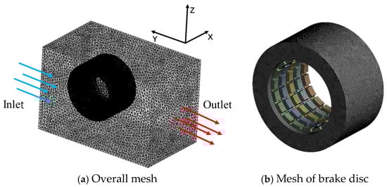
Figure 3.
Finite element model of brake disc.
3.2. Mesh
Given the complex and irregular area of the internal channel of the brake disc, a tetrahedral mesh is used. Tetrahedral meshes are selected for their ability to handle the complex geometry of the brake disc, particularly the irregular internal channels. While hexahedral meshes generally offer better accuracy and convergence for computationally demanding scenarios, their generation for such complex geometries can be challenging. Therefore, this paper selects tetrahedral meshing to ensure compatibility with simulation tools and maintain a good balance between accuracy and computational cost. For the cylindrical fluid domain, the encrypted mesh is used to improve the mesh quality and calculation accuracy, as shown in Figure 3b. For the rectangular fluid domain, the mesh size is increased without affecting the mesh quality, the number of meshes is reduced, and calculation time is saved [15]. A growth ratio of 1.2 was applied in our calculations to ensure smooth transitions between mesh elements and accurate heat flow analysis. The number of meshes is 739,236, and the average quality of the mesh is 0.84. The average orthogonal quality of the mesh is 0.78 and the average ortho-skew quality of the mesh is 0.22. The mesh division of the entire calculation area is shown in Figure 3a.
3.3. Governing Equations and Boundary Condition
The calculation domain adopts the k-ε turbulence model based on the Navier–Stokes equations. The air around the brake disc is regarded as a Newtonian fluid. The flow follows the laws of conservation of mass, momentum, and energy. The equation describing the control principle is as follows [16].
Continuity equation:
Momentum equation:
Energy equation:
where p and are the density and pressure, respectively; u, , cp, , and T are the velocity, dynamic viscosity, specific heat capacity, thermal conductivity, and temperature, respectively.
Standard k-ε turbulence model equations
where , and the term represents the turbulent kinematic viscosity, that is, . , , and are all constants; represents the turbulent Prandtl numbers for .
During the braking process, there is a temperature difference between the contacting brake discs, leading to heat transfer. Since the temperature of the brake discs changes over time, the heat conduction during braking is a three-dimensional transient heat conduction problem. The heat conduction differential equation is as follows:
where is the internal heat source.
The high-speed rotation of the brake disc causes irregular airflow in the surrounding air, leading to heat transfer between the air and the brake disc surface. This process falls under forced convective heat transfer and follows Newton’s law of cooling.
where is the heat flow rate; A is the solid surface area; and are wall temperature and fluid temperature, respectively; and h is the average convective heat transfer coefficient. In this study, an average heat transfer coefficient was employed to streamline the numerical model and cut computational expenses. Although it offers a fair approximation of overall temperature, it may overlook localized heat transfer variations.
Since the temperature range studied has little effect on the physical parameters, constant physical properties are used for calculation. The simulated physical parameters are shown in Table 5. The boundary conditions used in the calculation are as follows:
Table 5.
Physical parameters in numerical simulation.
- (1)
- The rotational angular velocity of the brake disc solid domain and the cylindrical fluid calculation area is equal to the rotational angular velocity of the aircraft axis, and the rotation axis is the X axis.
- (2)
- Inlet boundary: the air inlet surface is set as the velocity inlet, and the air flow direction is perpendicular to the surface, along the Y axis, and the wind speed is equal to the aircraft braking speed, simulating the wind speed that the aircraft is subjected to during actual braking.
- (3)
- Outlet boundary: the air outlet surface is set as the pressure outlet, the pressure is equal to the atmospheric pressure, and the wall temperature is set to 300 K.
- (4)
- Wall conditions: the two friction walls of the brake disc solid domain are applied with time-varying heat flux density, and the initial temperature of the other fluid–solid coupling walls is set to 300 K. The other four surfaces of the rectangular fluid domain are stationary walls, and the thermodynamic boundaries are set as adiabatic.
3.4. Numerical Method
The numerical simulation of the flow and heat transfer process is conducted using Ansys Fluent v2022, which allows for the calculation of basic physical quantities such as velocity, temperature, and pressure in the flow field through computational fluid dynamics (CFD) calculations. The control equations are discretized using the finite volume method to handle complex geometric shapes and boundary conditions. To deal with the coupling problem of pressure and velocity, the SIMPLE algorithm was adopted. The pressure term is discretized using the standard difference format, while the second-order upwind method is used for other terms during the difference process. The k-ε turbulence model was introduced in numerical simulations to capture the regularity of fluid flow and applied in transient calculations. In solution controls, the under-relaxation factors were set to 0.8 for turbulent kinetic energy, 0.4 for momentum, and 0.3 for pressure. To ensure the accuracy and reliability of the results, the convergence residuals of the energy equation and other variables were required to be less than 10−6.
4. Results and Discussion
4.1. Analysis of the Airflow Field Around the Brake Disc
Under braking conditions, the horizontal and rotational movements of the brake disc cause large disturbances in the surrounding air, and the surrounding air movement state is relatively complex. The flow rate of the air around the brake disc affects the convective heat transfer capacity of the brake disc surface, so analyzing the movement of the air around the brake disc is important for studying the heat dissipation performance of the brake disc.
The air flows in along the Y-axis direction, and the inlet wind speed is the same as the braking speed of the aircraft. The air velocity field around the brake disc at 10 s and 25 s—that is, at the end of braking—are shown in Figure 4. From Figure 4a, it can be seen that along the direction of air flow, the air flow velocity in the left area (also known as the windward area) of the brake disc is higher than that in the right area (also known as the leeward area), due to the effect of brake disc rotation resistance. From Figure 4a,b, it can be seen that the flow velocity in the upper and lower edge areas of the brake disc is relatively large, which is due to the disturbance effect of the brake disc. At the end of braking, the airflow velocity in the windward area has dropped to zero, but an obvious wake effect can still be observed at the rear of the brake disc.
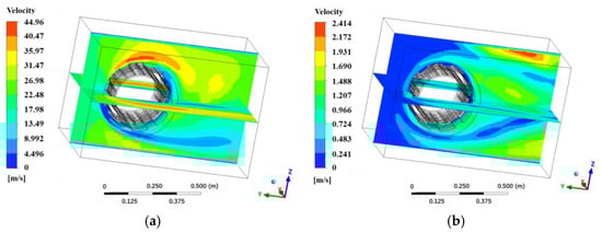
Figure 4.
The air velocity field around the brake disc at different times: (a) 10 s; (b) 25 s (i.e., the end of braking).
4.2. Analysis of Brake Disc Temperature Field
The change in brake disc temperature will have a great impact on the braking effect, so it is necessary to analyze the temperature field of the brake disc. For the end of braking, the temperature field of the brake disc is shown in Figure 5. Due to the symmetry of the brake disc structure and the effect of rotating friction heat generation, the temperature distribution on both the stator discs and the rotor discs is relatively uniform. The temperature curve of the overall average temperature of the brake disc over time is shown in Figure 6. As the braking time increases, the average temperature of the brake disc gradually increases, and due to the existence of heat dissipation, the rate of temperature increase gradually decreases.
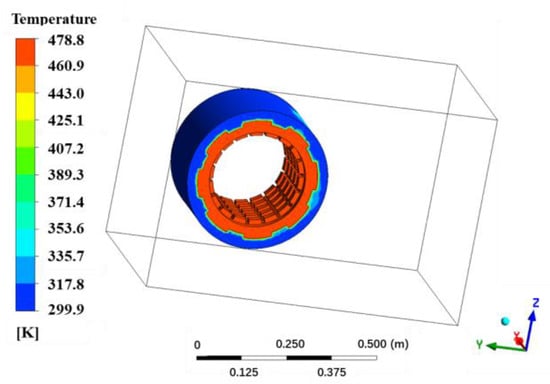
Figure 5.
Temperature field at end of braking.
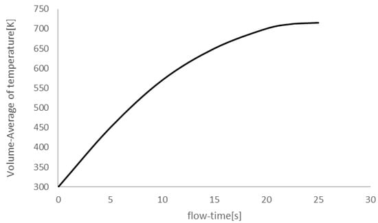
Figure 6.
Average temperature change curve of brake disc during braking process.
4.3. Experiment Analysis
In order to further verify the accuracy of the numerical simulation, an experimental study was conducted. The test bench is shown in Figure 7a. K-type thermocouples are placed on the internal parts to measure the temperature changes during braking. The schematic diagram of the positions of various temperature measurement points is shown in Figure 7b.
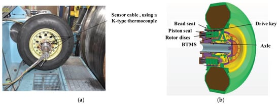
Figure 7.
Experimental diagram: (a) photo of thermocouple layout; (b) schematic diagram of thermocouple layout.
The experimental design conditions are as follows: the aircraft brake disc speed is 22 r/s and the braking time is 15 s, after which the aircraft stops, and the brake system enters the natural convection heat dissipation state. The energy is approximately 33 MJ when heat begins to dissipate using normal grounding without reverse thrust. The temperature change curves of each component in the experiment are drawn according to the temperature change of the thermocouple and compared with the simulated temperature change curves, as shown in Figure 8. Comparing and analyzing the temperature curve experimental data and simulation results of the rotor disc, it was found that the two were in good agreement. The maximum absolute error between the experiment and simulation is 29 K, and the maximum relative error does not exceed 4.5%, further confirming the reliability of the simulation model.
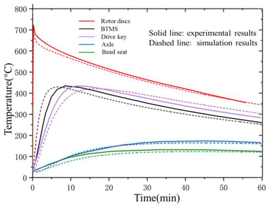
Figure 8.
Comparison of temperature changes between experiments and simulations under natural convection.
There are three main sources of error: (1) the simplification of material properties: numerical simulations often treat the thermal physical parameters of materials, such as specific heat capacity and thermal conductivity, as constant and isotropic, ignoring their temperature-dependent characteristics, resulting in deviations between simulation results and actual situations; (2) boundary condition setting: in numerical simulations, the convective heat transfer coefficient is set based on the empirical average value, but, in reality, this coefficient dynamically changes over time and has a spatial distribution, causing errors; (3) experimental measurement: during the experiment, errors may be introduced in terms of thermocouple accuracy, measurement location selection, and environmental factors such as air flow and radiation heat loss.
To compare the cooling effects of natural convection and forced convection, the fan is turned on for cooling after the vehicle stops. Figure 9 combines both the simulated temperature change curve and the experimental results for direct comparison; the simulation and experimental results are in good agreement. In this condition, the upper limit of energy for melting the fusible plug is adopted, which is approximately 48 MJ. It can be concluded that the cooling efficiency of forced convection is higher than that of natural convection.
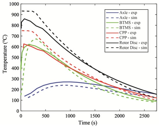
Figure 9.
Temperature change chart obtained from simulation and experiment under forced convection.
5. Conclusions
This study investigated the heat transfer behaviour of brake discs in a medium-sized passenger aircraft during braking through full-scale numerical simulation and experimental research, revealing the temperature distribution and heat transfer mechanism of brake discs during braking, and providing an important theoretical basis and practical guidance for the design and optimization of brake discs. Future research can further explore the temperature dependence of material properties, heat transfer mechanisms under complex boundary conditions, and more efficient heat dissipation strategies to enhance the overall performance and safety of brake systems. The main conclusions are as follows:
- (1)
- The surface temperature of the brake disc rapidly increases during the braking process, creating a significant temperature gradient, especially in the early stages of braking. This temperature gradient may cause thermal stress and material fatigue. Therefore, during design, special attention should be paid to material selection and structural design in areas with high temperature gradients to prevent cracks or deformations caused by thermal stress.
- (2)
- The air flow has a significant impact on the heat dissipation efficiency of brake discs, and the higher the flow speed, the better the heat dissipation effect. Even in the later stages of braking, air disturbance remains significant, indicating that forced convection (such as with a fan) at low speeds or when stopped can significantly improve heat dissipation efficiency. Therefore, the introduction of forced convection devices in practical applications can effectively accelerate the cooling of brake discs.
- (3)
- Experimental verification shows that the maximum relative error between numerical simulation results and experimental data is about 4.5%, indicating the high reliability of the model. The errors mainly come from the simplification of material properties, boundary condition settings, and experimental measurement uncertainties. To improve simulation accuracy, future research can adopt material thermophysical parameters that vary with temperature and optimize boundary conditions, especially the dynamic changes in convective heat transfer coefficients.
Author Contributions
Methodology, Q.M.; Software, H.S.; Validation, B.L.; Resources, Z.J. All authors have read and agreed to the published version of the manuscript.
Funding
This research was funded by the Natural Science Foundation of China (Grant Number 52205063).
Institutional Review Board Statement
Not applicable.
Informed Consent Statement
Not applicable.
Data Availability Statement
The original contributions presented in this study are included in the article. Further inquiries can be directed to the corresponding author.
Conflicts of Interest
The authors declare no conflict of interest.
References
- Pevec, M.; Potrc, I.; Bombek, G.; Vranesevic, D. Prediction of the cooling factors of a vehicle brake disc and its influence on the results of a thermal numerical simulation. Int. J. Automot. Technol. 2012, 13, 725–733. [Google Scholar] [CrossRef]
- Deren, E.A.; Volkhonsky, A.E.; Konoval, D.V. Computer simulation of heat transfer processes in aircraft landing gear braking mechanisms. IOP Conf. Ser. Mater. Sci. Eng. 2021, 1111, 012018. [Google Scholar] [CrossRef]
- Schmidt, D.L.; Davidson, K.E.; Theibert, L.S. Unique applications of carbon-carbon composite materials (part three). Sampe J. 1999, 35, 47–55. [Google Scholar]
- Afzal, A.; Abdul Mujeebu, M. Thermo-mechanical and structural performances of automobile disc brakes: A review of numerical and experimental studies. Arch. Comput. Methods Eng. 2019, 26, 1489–1513. [Google Scholar] [CrossRef]
- Bauzin, J.-G.; Laraqi, N. Three-dimensional analytical calculation of the temperature in a brake disc of a high-speed train. Appl. Therm. Eng. 2019, 154, 668–675. [Google Scholar] [CrossRef]
- Singh, S.K.; Abbassi, H.; Tamamidis, P. 3D investigation into the thermal behavior of the wet multi-disk axle brake of an off-highway machinery. Appl. Therm. Eng. 2018, 136, 576–588. [Google Scholar] [CrossRef]
- Belhocine, A.; Omar, W.Z.W. CFD analysis of the brake disc and the wheel house through air flow: Predictions of Surface heat transfer coefficients (STHC) during braking operation. J. Mech. Sci. Technol. 2018, 32, 481–490. [Google Scholar] [CrossRef]
- Kennedy, F.E., Jr.; Ling, F. A thermal, thermoelastic, and wear simulation of a high-energy sliding contact problem. J. Lubr. Technol. 1974, 96, 497–505. [Google Scholar] [CrossRef]
- Qi, H.S.; Day, A.J. Investigation of disc/pad interface temperatures in friction braking. Wear 2007, 262, 505–513. [Google Scholar] [CrossRef]
- Grzes, P. Maximum temperature of the disc during repeated braking applications. Adv. Mech. Eng. 2019, 11, 1687814019837826. [Google Scholar] [CrossRef]
- Nosko, A.L.; Mozalevb, V.V.; Nosko, A.P.; Suvorov, A.V.; Lebedeva, V.N. Calculation of temperature of carbon disks of aircraft brakes with account of heat exchange with the environment. J. Frict. Wear 2012, 33, 233–238. [Google Scholar] [CrossRef]
- Lei, L.; Yi, M.; Xu, H. 3-D temperature field for C/C composite braking discs. Acta Mater. Compos. Sin. 2009, 26, 113–117. [Google Scholar]
- Peszynska-Bialczyk, K.; Anderson, K.; Szymanski, T.; Krkoska, M.; Filipet, P. Thermal analysis of bulk carbon–carbon composite and friction products derived from it during simulated aircraft braking. Carbon 2007, 45, 524–530. [Google Scholar] [CrossRef]
- Bauzin, J.; Keruzore, N.; Laraqi, N.; Gapin, A.; Diebold, J. Identification of the heat flux generated by friction in an aircraft braking system. Int. J. Therm. Sci. 2018, 130, 449–456. [Google Scholar] [CrossRef]
- Cant, R.S.; Ahmed, U.; Fang, J.; Chakarborty, N.; Nivarti, G.; Moulinec, C.; Emerson, D.R. An unstructured adaptive mesh refinement approach for computational fluid dynamics of reacting flows. J. Comput. Phys. 2022, 468, 111480. [Google Scholar] [CrossRef]
- Shen, H.; Liu, C.; Yang, L.; Wang, Y. Pore-scale numerical investigation on comprehensive heat transfer performance of homogeneous and graded metal foam heat sinks. Therm. Sci. 2024, 28, 1529–1544. [Google Scholar] [CrossRef]
Disclaimer/Publisher’s Note: The statements, opinions and data contained in all publications are solely those of the individual author(s) and contributor(s) and not of MDPI and/or the editor(s). MDPI and/or the editor(s) disclaim responsibility for any injury to people or property resulting from any ideas, methods, instructions or products referred to in the content. |
© 2025 by the authors. Licensee MDPI, Basel, Switzerland. This article is an open access article distributed under the terms and conditions of the Creative Commons Attribution (CC BY) license (https://creativecommons.org/licenses/by/4.0/).