Article

Integrated Analysis of Optimization and Settlement Characteristics in Hybrid Pile Systems for Reused Foundations

1
Installation Engineering Co., Ltd., CSCEC 7th Division, Zhengzhou 450000, China
2
China Construction Seventh Engineering Division, Co., Ltd., Zhengzhou 450004, China
3
School of Human Settlements and Civil Engineering, Xi’an Jiaotong University, Xi’an 710049, China
4
Department of Civil and Environment Engineering, National University of Singapore, Singapore 117576, Singapore
*
Author to whom correspondence should be addressed.
Appl. Sci. 2025, 15(6), 3016; https://doi.org/10.3390/app15063016
Submission received: 5 February 2025 / Revised: 6 March 2025 / Accepted: 8 March 2025 / Published: 11 March 2025

Abstract

:
Pile reuse is a common technique in bridge renovation projects. However, the interaction mechanisms between new and existing piles under a shared cap remain unclear, restricting the size setting and further optimization of new piles in existing pile foundation environments. This study analyzes the effects of key parameters for new piles on the settlement behavior of existing piles under a shared pile cap using field measurement data and simulation results. The findings indicate that, within one pile cap, the settlement of both new and existing piles exhibits a negative correlation with the increasing new pile length. With the different load distribution patterns, the settlement differences between new and existing piles tend to be more stable in a lateral arrangement compared to a symmetrical distribution. Additionally, the pile cap size has a boundary effect on the combined pile system, specifically, as the pile cap length/width ratio is 4:2, the settlement disparity between new and existing piles tends to stabilize. Settlement behavior is also significantly affected by soil properties, with stiffer soils (higher elastic modulus) showing smaller settlements. Introduce the existing pile efficiency parameter, the main factors influencing settlement behavior rank as follows: soil properties, load distribution, pile distribution, pile length, pile diameter, and pile cap size. Based on these findings, it is recommended that the length of new piles be controlled to 1.0–1.1 times the length of existing piles, and the diameter of new piles be 1.0–1.2 times the diameter of existing piles. The study explores the interaction effects between new and existing piles, aiming to optimize the performance of pile reuse.

1. Introduction

Pile foundations are a core technology in construction engineering, with load-bearing capacity and settlement characteristics being key research areas. Traditional optimization and construction methods for pile foundations are relatively mature [1,2,3], research primarily focuses on exploring the effects of pile shape, external load patterns, and subsurface lithology on pile-bearing capacity and pile-soil interaction. The research methodologies include theoretical analysis, field tests, and numerical simulations. Studies have shown that pile-pile interaction can be influenced by pile shape, external load patterns, and soil properties [4,5,6]. With the continuous development of urban construction, pile engineering is becoming increasingly complex [7], especially in renovation projects where numerous existing piles are left in place.
When dealing with existing pile foundations, two common methods are considered: remove and reuse. However, removing existing piles not only increases construction costs but also significantly reduces soil stability [8,9]. Therefore, the reuse of existing piles has become a new research direction in geotechnical engineering [10]. Researchers evaluate the load-bearing capacity of existing piles for reuse [11,12], which greatly reduces environmental pollution and resource waste [13,14]. Compared to existing structures, new bridges often require higher load demands, necessitating the addition of a specific number of supplementary piles in the foundation to ensure the safety of the new bridge. The existing pile foundations have been in the ground for many years, and the surrounding soil has consolidated or aged due to long-term loading [15,16,17]. Therefore, under the same applied load, uneven settlement may occur between new and existing piles due to differences in load history. Identifying these differences and implementing targeted improvements could effectively control potential engineering hazards caused by differential settlement.
Poulos [18] found through theoretical research that existing piles are subjected to axial forces and bending moments due to the driving of adjacent piles, causing structural damage or tensile failure. Li and Gong [19] proposed an analysis system based on load transfer and shear displacement methods to predict settlement interaction between new and existing piles. Some researchers have also conducted theoretical analyses on the installation process of new piles [20,21,22,23]. In addition to theoretical research, Begaj and McNamara [24] found through centrifuge tests that the addition of new piles improved the performance of existing pile foundations. Tamura et al. [25] used vertical static load centrifuge tests to study the impact of existing piles on the vertical bearing capacity of new piles, showing that existing piles provide constraint to the surrounding soil, increasing the total shaft resistance of new piles. However, theoretical analyses and model tests have limitations in comparing a large number of working conditions, especially in complex geological conditions. Numerical simulations can quickly achieve different condition comparisons to overcome these limitations. For example, finite element analysis, as a continuum method, can automatically consider pile-soil coupling, which traditional load transfer methods cannot achieve [3]. Li et al. [26] used numerical experiments to study the impact of existing piles on new pile construction at different pile spacings. Additionally, Li et al. [27] analyzed the contribution of the fixed degree of existing pile heads to the lateral load response of new piles through numerical simulation and proposed a new pile design method considering the fixed degree of existing pile heads. Tamura [25] used finite element analysis to assess the influence of existing piles on the lateral resistance of new piles. Brian [10] used finite element software to analyze the impact of creep under certain loads on the bearing capacity of reused pile foundations with additional existing piles, finding that increasing the length of existing piles under reloading has little improvement in bearing capacity and stiffness.
Numerical simulations have advanced the study of interactions between new and existing piles under different conditions. However, there is still a lack of research on the factors influencing the mechanisms of new and existing piles under the constraint of a shared pile cap. This study focuses on the impact of new piles on existing piles under various conditions after the installation of new piles, forming a new pile cap. By comparing the settlement of existing piles under identical loads with and without new piles, the study quantifies the impact of different parameters. Field test data are used to validate the model parameters, with new pile length (hN) and diameter (dN) being the primary variables. External factors such as pile cap length-width ratio, pile arrangement, soil properties, and load eccentricity are also considered to examine their effects on the interaction between new and existing piles. The findings aim to guide the design of new piles, considering the reuse of existing piles.

2. Research Overview

The study area is located in Zhengzhou, Henan Province, where multiple bridges intersect. The substructure of these bridges is supported by pile foundations to ensure the safety of the superstructure; the settlement of the original pile foundations had stabilized with prolonged soil consolidation. However, with the rapid urban development, the original bridge width and load-bearing capacity are no longer sufficient to meet traffic demands. Therefore, it has been proposed to add new pile foundations to meet the new design requirements. Besides demolishing the superstructure for bridge reconstruction, another method is to directly widen one side of the existing bridge. This study mainly focuses on the reconstruction of the bridge section, where the existing pile foundations are reused, as shown in Figure 1. The existing pile foundations in the demolition area are grouped into fours, with two new pile foundations added to form a new foundation structure through the cap. The research area is relatively flat, and the stratum is mainly composed of silt, silty clay, and a certain thickness of fine sand layer. To minimize differential settlement when the new bridge operates on the foundations of both new and existing piles, and to enhance construction efficiency and safety, it is crucial to reasonably select the parameters for the new piles and implement appropriate reinforcement measures.

3. Pile-Soil Numerical Model

3.1. Pile-Soil Mechanical Model

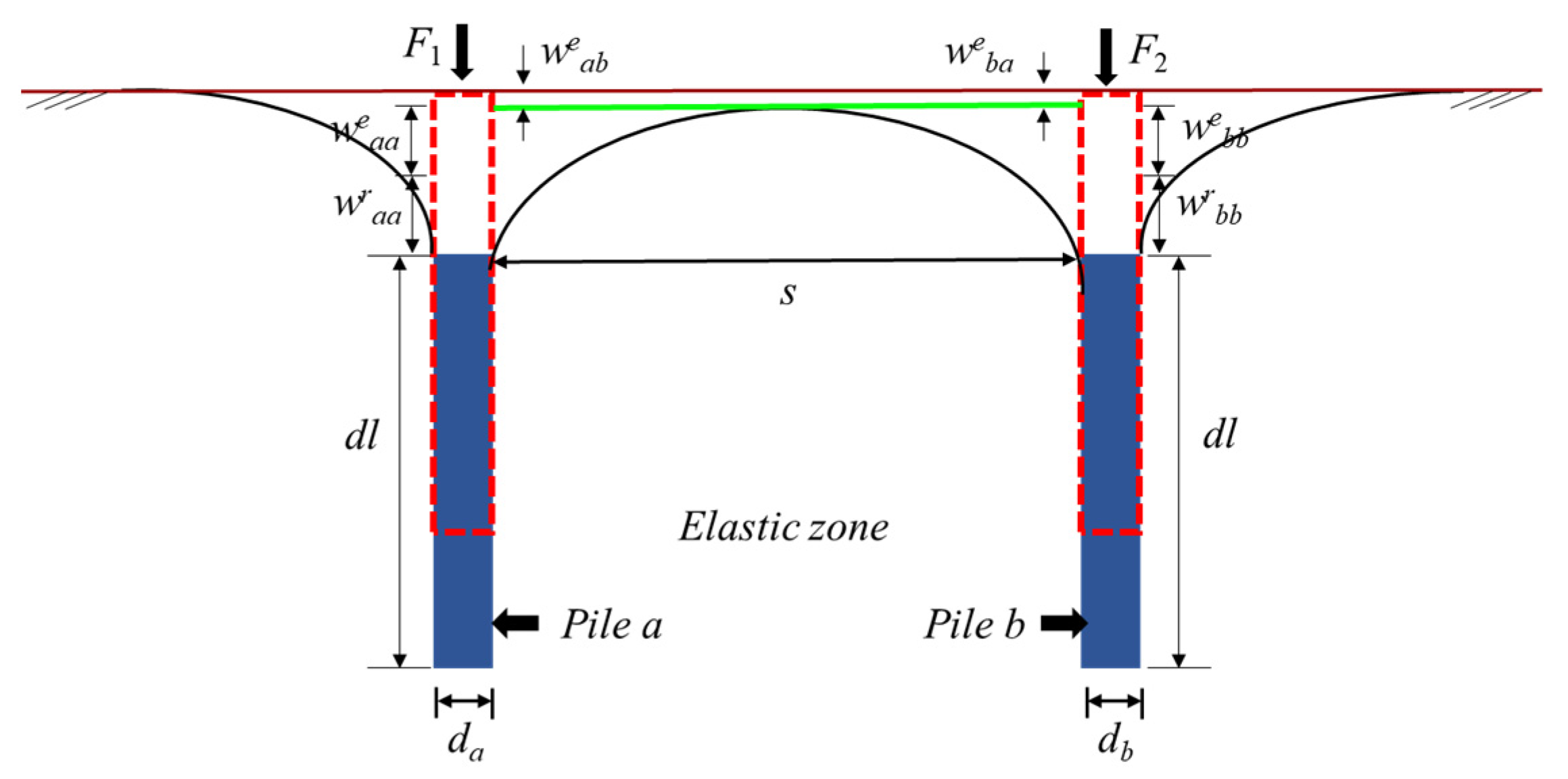
The mechanical interaction of bored piles typically manifests in the pile-soil and pile tip-soil interfaces. For bored piles under axial loading, the displacement of the soil around the pile shaft consists of both nonlinear and purely elastic displacements [28]. Figure 2 shows the interaction between adjacent piles in a pile group foundation. In addition to their own settlement, wraa and weaa represent the nonlinear and elastic displacements, respectively, of pile-a due to its own load F1. Similarly, wrbb and well represent the nonlinear and elastic displacements, respectively, of pile-l due to its own load F1. weab denotes the additional elastic displacement of pile-a applied to pile-b due to the load, and weba is the additional elastic displacement of pile-b applied to pile-a due to the load.
In addition, the mutual reinforcement effect between adjacent piles cannot be neglected in the vertical settlement of pile groups [19]. Considering the consolidation effect in the calculation of vertical displacement of pile groups and combining the settlement factors mentioned in Figure 2, the total settlement of any pile in a pile group foundation can be divided into self-load, load applied to adjacent piles, and the reinforcement effect of adjacent piles. The settlement caused by the reinforcement effect can be referenced from Huang [29].
Existing piles have certain unknown consolidation effects due to long-term historical loading and unloading. When new bored piles are added, the consolidation effect on existing piles is smaller compared to that on adjacent piles of the same period. Additionally, when new and existing piles act under a shared pile cap, it is unclear whether the settlement of new and existing piles constrained by the pile cap will cause deviations from theoretical analysis. However, these factors are relatively complex to reflect in a mechanical model. This study will analyze these effects by establishing a numerical model of the pile-soil system.

3.2. Pile-Soil Numerical Model

3.2.1. Model and Boundary Conditions

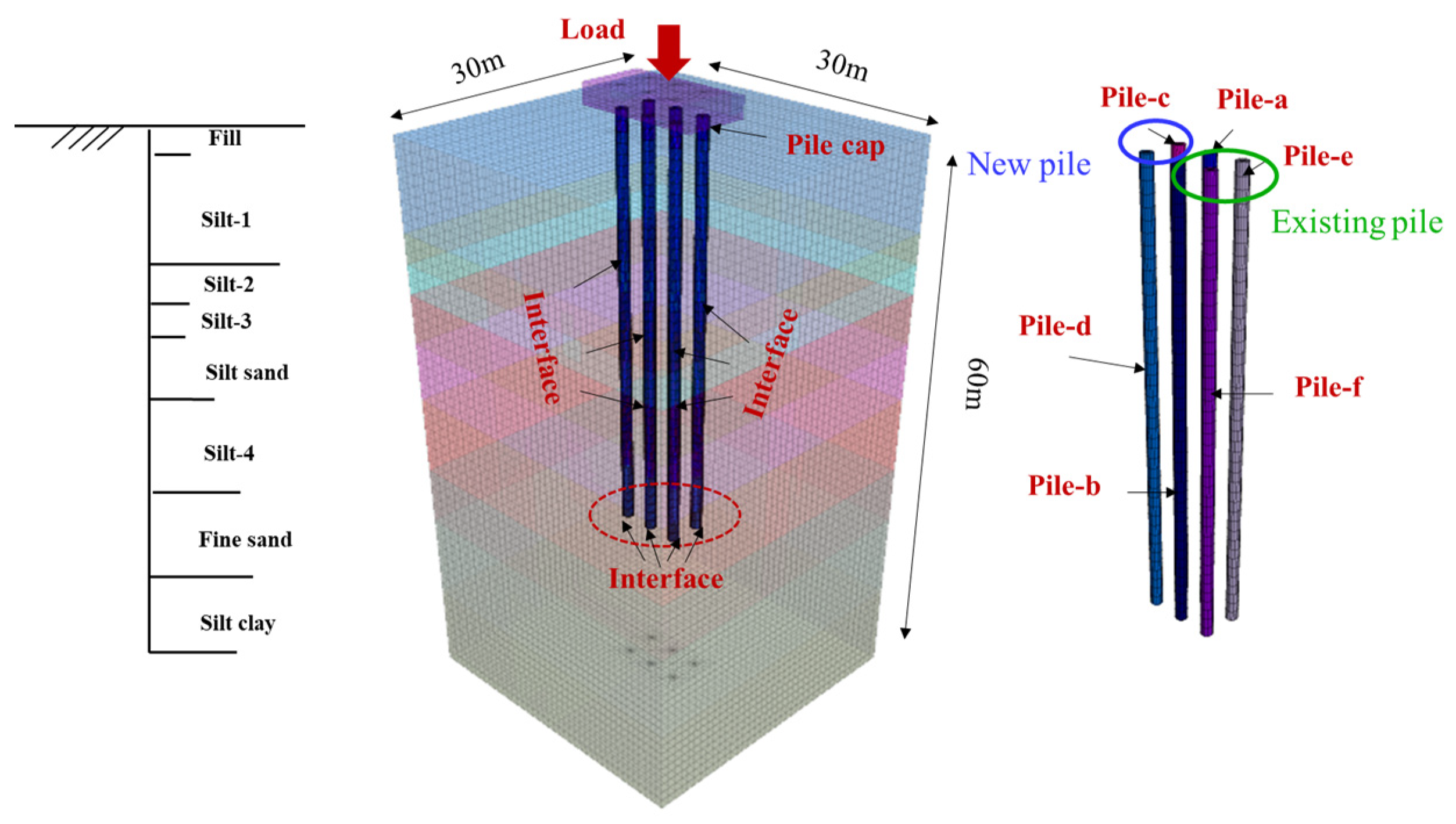
The finite difference (FD) software [30] was used to establish a geometric model identical to that of the actual engineering project, simulating the interaction between new piles, soil, and existing piles. Figure 3 shows the dimensions of the model and pile distribution used for the study analysis (length of the existing pile: h is 42 m, diameter of the existing pile: d is 1 m). The stratigraphic conditions of the model were established based on actual borehole data, as shown in Table 1. The pile foundations are divided into the existing pile under the original bridge and a new pile, consistent with the actual working conditions. All displacements at the bottom of the model are constrained, and normal displacements at the side boundaries of the model are restricted. The pile heads of the new and existing piles are connected by a pile cap with dimensions of 12 × 6 × 2 m (length L × width B × depth Hp). The spacing between the new pile and existing piles is set to 2d.
The soil behavior in the model was assumed to follow an elastic-plastic constitutive relation based on the Mohr-Coulomb criterion, which is commonly applied in analysis models of both new and existing piles [6,10,30,31,32], and is widely used in rock and soil materials and has also been applied in the analysis models of new and existing piles in recent years [33,34,35], and could effectively reflect the pile-soil interaction. The material characteristic parameters of the soil layers used in the model are shown in Figure 4. The piles and pile caps are modeled as elastic solid elements [36]. The model parameters are based on measurements from the actual engineering project, and the specific pile parameters and conditions are summarized in Table 2.

3.2.2. Contact Settings

When describing the pile-soil interface of bored piles, contact parameters are used to quantify the soil-pile interface. Referring to the contact model parameter formula mentioned by Chen and Xu [37]:
K s = K N = 10 max ( K + 4 3 G ) Δ z min
K = E 3 ( 1 2 v )
G = E 2 ( 1 + v )
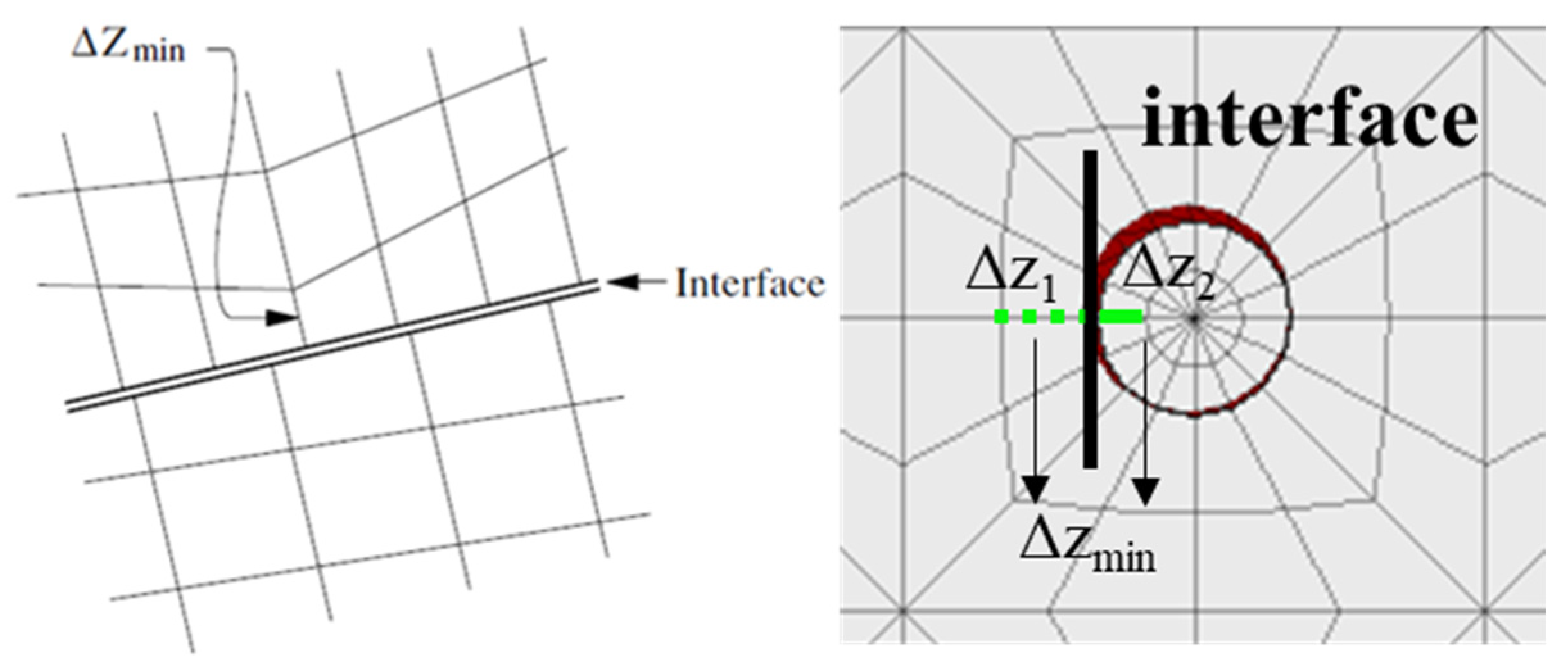
K represents bulk moduli of the equivalent stiffness of the stiffest neighboring zone; G represents shear moduli of the equivalent stiffness of the stiffest neighboring zone; the internal friction angle φ at the contact interface can be set to 0.5 to 0.8 times that of the adjacent soil layers. Δzmin represents the smallest width of an adjoining zone in the normal direction (see Figure 4).

3.2.3. Loading Process

To restore the loading history of the existing piles, the model introduces four 1 m (diameter) × 42 m (height) piles after geostress balance is achieved and then applies historical loads to the pile head. After the model calculation reaches stability, the overlying loads are removed, and the historical displacement is cleared. New piles are constructed around the existing piles according to the design scheme, with the addition of pile-soil interface parameters. The pile cap structure above the new and existing piles is then activated, and a vertical load is applied to the surface of the pile cap. The load is applied according to the allowable bearing capacity of the pile, as shown in Figure 5d–e. Meanwhile, the settlement and lateral displacement of the new and existing piles, as well as stress and deformation, are monitored in real-time during the loading process.

3.3. Verification of the Numerical Model

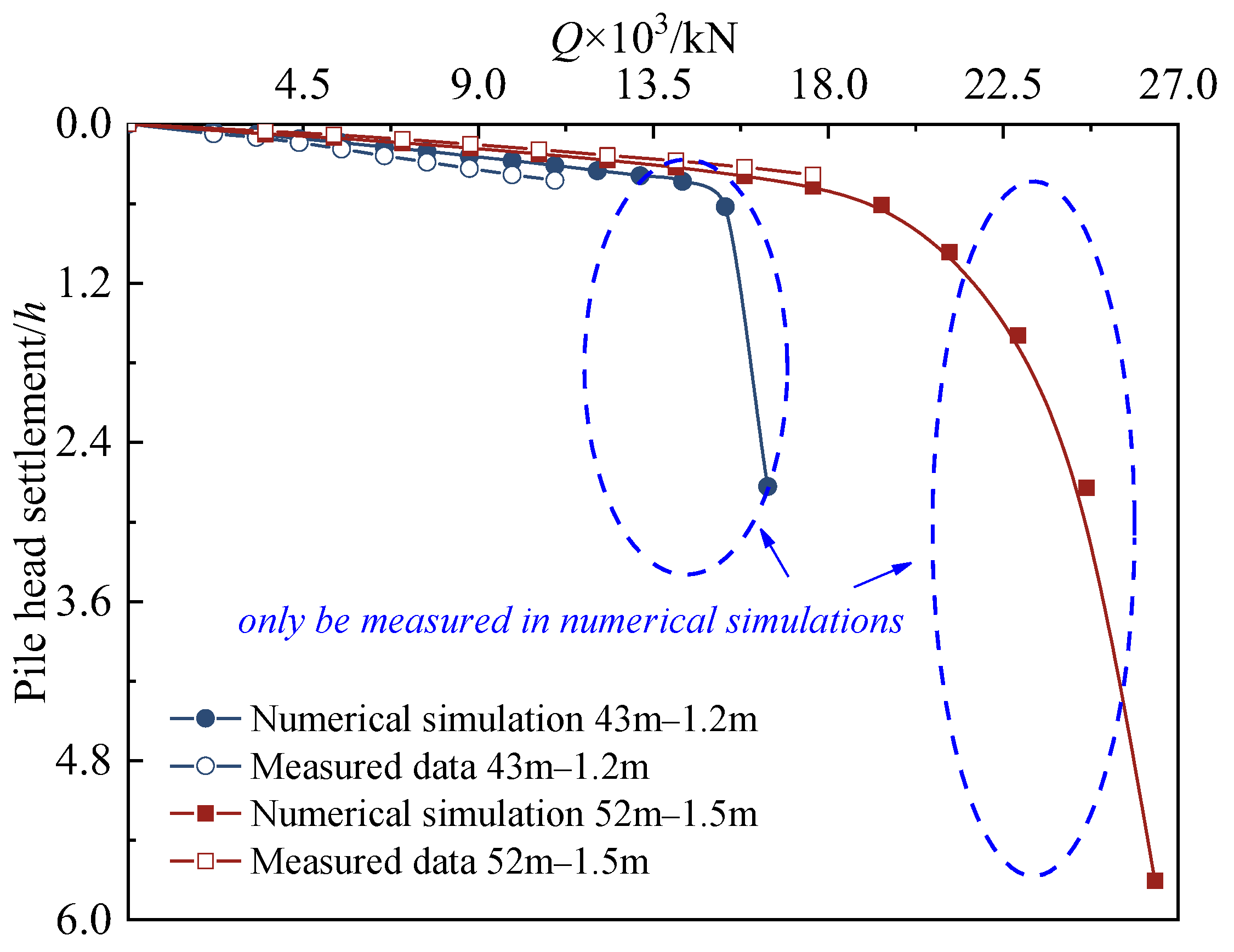
Two single-pile numerical models (pile lengths of 43 m and 52 m, diameters of 1.2 m, and 1.5 m) were established based on field static load tests, with graded loading applied at the pile head (as shown in Figure 6). The numerical results closely match the measured settlement data, confirming the applicability of the selected parameters for studying the interaction between new and existing piles. Since the field test piles needed to remain functional for future use, the loading level was limited. Therefore, additional loading was applied in the numerical simulations. The results indicate that the field tests underestim ated the actual ultimate bearing capacity, while the numerical analysis revealed the pile’s deformation and bearing characteristics under higher loads, suggesting that the field test evaluation was relatively conservative. This study validates the reliability of the numerical model and provides a foundation for optimizing pile design and investigating new existing pile interactions.

4. Interaction Between Parameters of New and Existing Piles

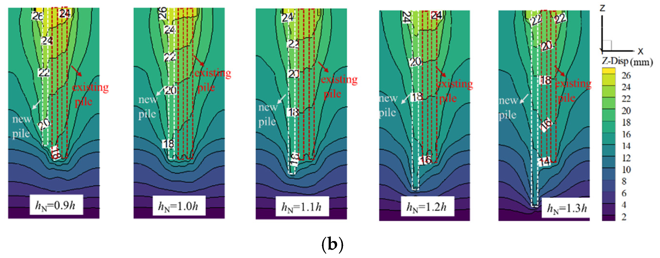
Figure 7a,b show the displacement contour results of new and existing piles under two cases: (1) dN (0.8–1.5d) hN (1.0h), (2) hN (0.8–1.3h) dN (1.0d), subjected to the allowable vertical load (4934 kN). The behavior of new and existing piles varies due to the interaction between the new pile and the existing pile under different parameters.
In Figure 7a, with changes in the dN, the settlement range of the soil around the pile increases and then stabilizes. Additionally, the increasing dN provides more resistance at the pile-soil interface. Within the dN range of 0.8–1.5d, the displacement at the head of the new pile decreases from 28 mm to 22 mm, a reduction of approximately 21%. Similarly, within the hN range of 0.9–1.2h, the displacement decreases by approximately 4 mm. The displacement contour indicates that, with an increase in hN, the displacement value also gradually decreases, suggesting that a longer hN provides more resistance to settlement. However, the displacement contour of the soil around the pile remains relatively stable under different hN(s).

4.1. Behavior of New Piles

Figure 8 and Figure 9 show the vertical settlement deformation of new piles under different hN(s) and dN(s), respectively, subjected to a certain vertical load.
Figure 8 indicates a negative correlation between hN and pile foundation settlement. Within the range of 0.9–1.3h, the settlement of the new pile consistently decreases with the increase in hN. At the pile head, the settlement variation ranges from 0.481 to 0.417, while at the pile bottom, it ranges from 0.364 to 0.228. The influence of larger hN on the pile bottom gradually decreases. In the displacement contour, longer piles transfer the load to deeper soil layers, where the high confining pressure constrains pile foundation deformation, effectively reducing settlement. The deeper hN, the more pronounced the effect.
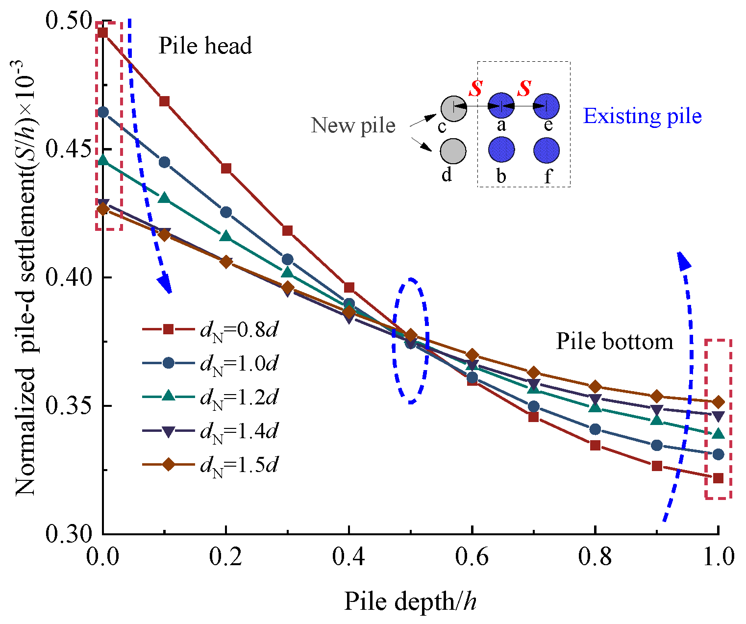
In the relationship between dN and the settlement of new piles, there is a notable attenuation at the pile head, then the settlement increased with dN. For both large-diameter piles and small-diameter piles, negative friction was distributed in the upper part of the pile and positive friction was distributed in the lower part of the pile, and the shaft friction of the large-diameter pile was greater than that of the small-diameter pile at the same depth [38]. This phenomenon can be attributed to the gradual dissipation of vertical soil stress between surface piles with increasing depth, while the negative friction in the upper section of the pile effectively offsets a portion of the vertical stress. In contrast, in the lower section, vertical soil stress increases due to the cumulative effects of soil self-weight and positive friction. Furthermore, the normal stress acting on the pile shaft is proportional to the vertical soil stress, leading to higher normal stresses on large-diameter piles. This effect becomes more pronounced as the diameter difference increases. Meanwhile, large-diameter piles carry greater loads; their pile-soil relative displacement is also more significant than that of small-diameter piles. These results indicate that pile diameter’s effect on settlement follows a nonlinear trend. At the initial stage, increasing the pile diameter significantly reduces settlement. However, as the pile diameter continues to increase, normal stress growth between piles and the pile-soil relative displacement may contribute to an increase in settlement.
Li’s study shows that the total bearing capacity Q(t) of an axially loaded pile consists of the end-bearing capacity Qs(t) and the side resistance Qb(t), expressed as [39]:
Q ( t ) = Q s ( t ) + Q b ( t ) = 0 l 2 π r p f s ( t ) d z + π r p 2 q b ( t )
where l is the pile length, rp is the pile radius, and qb is the unit end bearing resistance of a pile, defined as q b ( t ) = N c ( t ) s u 0 , t represents the consideration of time-dependent effects caused by clay creep, Su0 is the initial undrained shear strength of the soil, and Nc is the pile end coefficient. From the expression, both the increase in hN and dN enhance the overall bearing capacity. Theoretical explanations provide insights into the influence of hN and dN on pile-bearing capacity and settlement behavior. However, numerical simulations demonstrate that the settlement induced under identical vertical stress is relatively limited, particularly for variations in dN at a fixed pile length. When a new pile and existing piles are integrated into the same pile cap, the connection through the pile cap directly impacts the settlement of the existing piles, in addition to the soil-pile interaction.

4.2. Behavior of Existing Piles

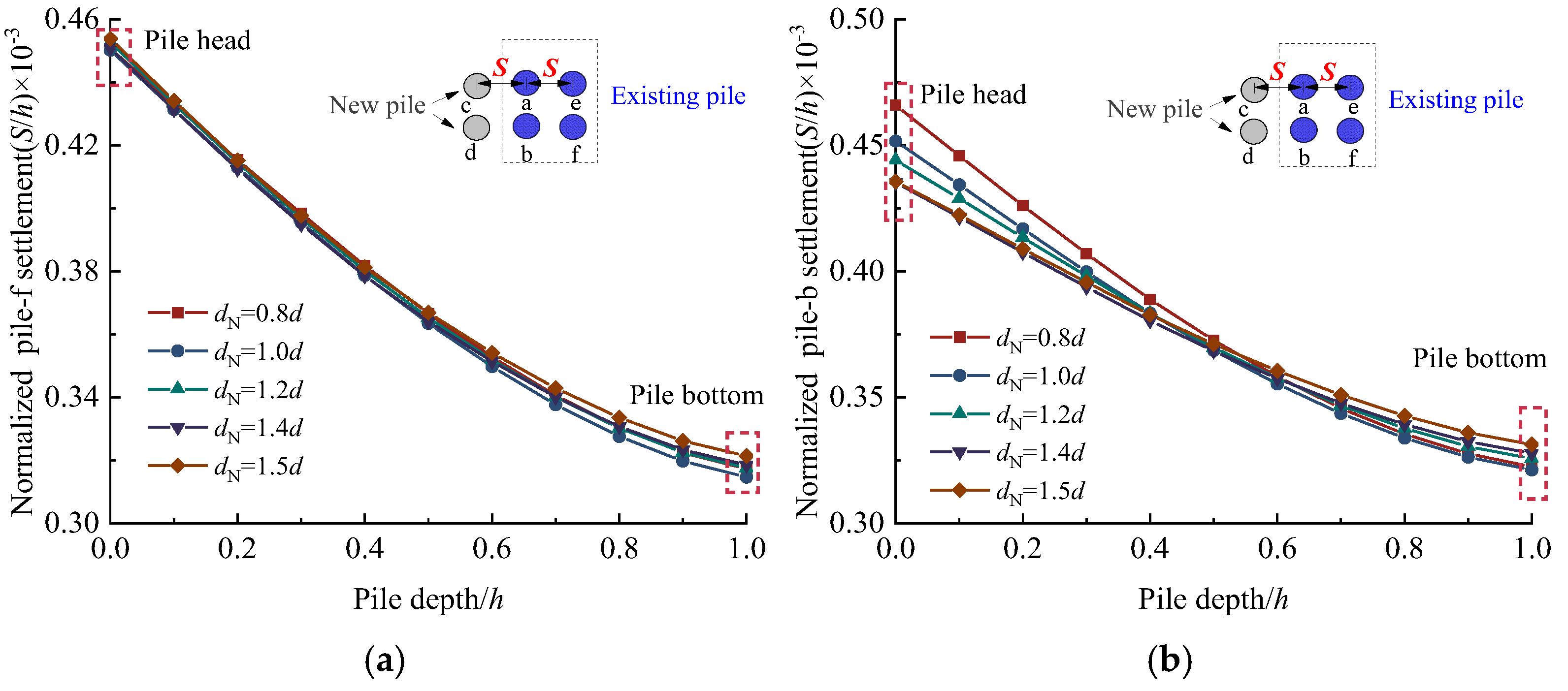
As new piles are introduced, the stress redistribution in the surrounding soil exerts pressure and remolding effects on adjacent existing piles [40,41]. Figure 10 and Figure 11 display the settlement results of existing piles under different hN(s) and dN(s) of the new piles. The results indicate a negative correlation between the settlement of existing piles and the increase in hN. The normalized settlement variation ranges from 0.46 to 0.41, with a stable gradient of change.
In the group pile model, the introduction of new piles will alter the load-sharing mechanism of the soil. Among them, an increase in hN can redistribute the overlying load, reducing the load borne by the existing pile and positively affecting the settlement control of the existing piles. The settlement of existing piles shows a positive correlation with the increase in the dN. After normalization, the settlement range of existing piles close to the new piles varies between 0.450 and 0.454, with only a small discrepancy across different parameters, ultimately stabilizing at 0.45.
The increase in dN reduces the net distance between piles. When new piles are introduced, the soil around the piles moves downward with pressure and friction, with the effect becoming more pronounced as the dN increases. This is evident from Figure 9. Consequently, adjacent existing piles also experience downward movement due to the influence of the moving surrounding soil. However, the impact of the increasing dN on the surrounding soil is limited, including the lateral influence range. As seen in Figure 11, the settlement influence of existing piles stabilizes at dN of 1.2d. Meanwhile, the existing pile (Pile b) near the new pile exhibits a settlement pattern along the depth direction that initially decreases and then increases with changes in pile diameter. However, the variation difference becomes significantly less than the new pile. By the time it reaches pile-f, this pattern has almost disappeared.

5. Study on the Behavior Parameters of Existing Piles

After the introduction of new piles, the surrounding soil structure is disturbed, leading to a decrease in its strength and stiffness [19], and the soil layer may undergo consolidation settlement [20]. Therefore, the response of the soil around the piles directly impacts the settlement of the existing piles. According to the load-settlement calculation formula for pile groups [29], pile settlement is primarily determined by load parameters, the shear modulus of the pile-soil interface, and the elastic modulus and stiffness of the soil beneath the pile. Under the one pile cap, the factors affecting load parameters include not only the load magnitude but also load distribution and load-bearing ratio. This section explores the load-settlement patterns of new and existing piles under different pile arrangements, pile cap sizes, and soil properties in a pile group interaction context.

5.1. Pile Arrangement

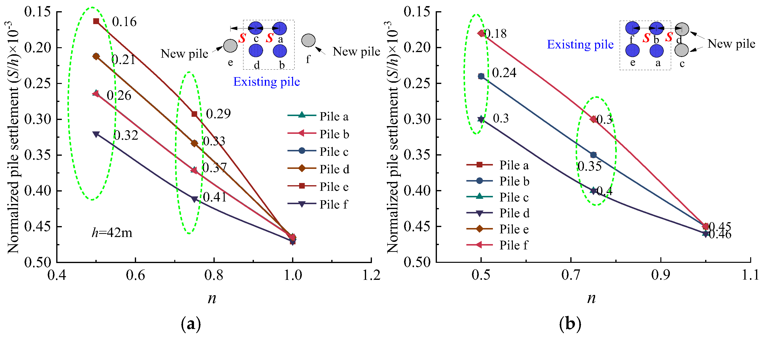
Common supplementary pile arrangements around existing piles include central positioning, dispersed around the existing pile, and gap-filling methods. Based on the original positions of the existing piles in this study, two pile arrangement forms are proposed: symmetric (new piles arranged on both sides of the existing piles) and lateral (new piles arranged on one side of the existing piles). The distance from the applied load to the center point of the pile cap (n = 1, 0.75, 0.5) is defined as e (0, 0.125L, 0.25L), as shown in Figure 12. For certain hN(s) and dN(s), the settlement differences under different arrangements of new and existing piles vary.
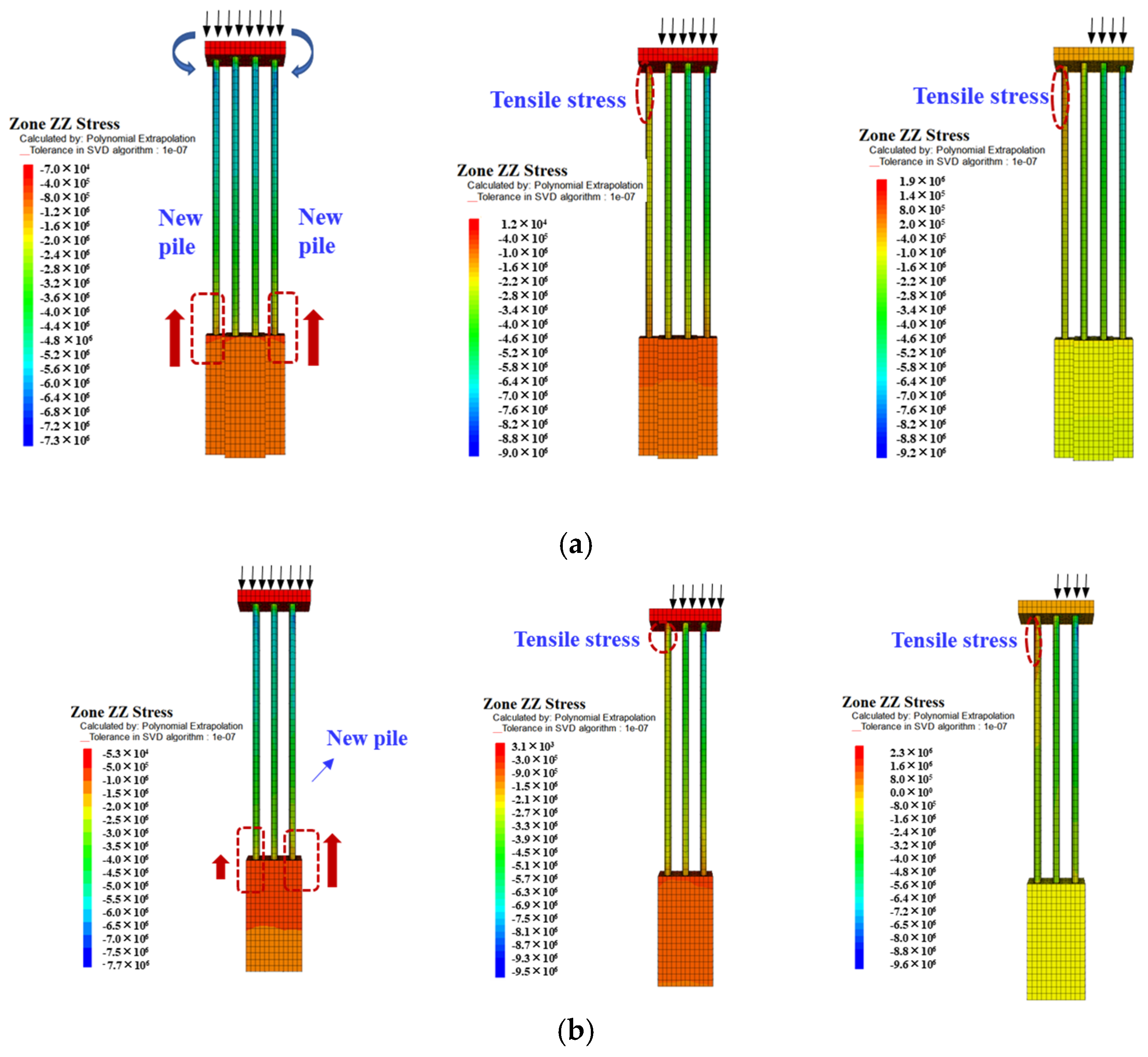
The form of pile arrangement determines the load-sharing mechanism between new and existing piles. Figure 13 shows the settlement results of existing piles under different load forms and pile arrangements. When the load is evenly distributed over the pile cap, the settlement of new and existing piles in the lateral arrangement is slightly higher than that in the symmetric arrangement. When the load is partially applied, the settlement difference between new and existing piles varies depending on the overlying load. As shown in the stress contour plot in Figure 14, under uniform load distribution, the stress difference between new and existing piles in the lateral arrangement is not significant, though the new piles experience relatively larger settlements. With the load shifting, the piles not subjected to the load experience uneven stress distribution due to lateral forces. The results under the symmetric arrangement are similar but numerically different from the lateral arrangement. Combining displacement and stress, the results indicate that eccentric loading is not advantageous for a symmetric pile arrangement. Under the same load variation, the symmetric pile arrangement slightly increases the difference between new and existing piles. At n = 0.75, the normalized settlement of the pile in the symmetric arrangement ranges from approximately 0.29 to 0.41, while the settlement difference in the lateral arrangement ranges from 0.30 to 0.40. At n = 0.5, the normalized settlement in the symmetric arrangement ranges from approximately 0.16 to 0.32, while the settlement difference in the lateral arrangement ranges from 0.18 to 0.30. Although the symmetric arrangement shows some advantages under uniform load (n = 1), considering the uncertainties of dynamic loads on the bridge in the later stages, the lateral arrangement would be simpler to reinforce.
In addition, Figure 14 shows that, in both arrangements, eccentric loads cause tensile stress in the unloaded piles, resulting in upward displacement and bending moment of the pile body, especially in the unloaded new pile. Therefore, in the context of new and existing piles, it is crucial to consider the impact of uneven settlement on bridge stability. Additionally, eccentric loading may induce tensile stress in the bridge pile, compromising the stability of the foundation. This consideration is a key factor in selecting the arrangement of new and existing piles.

5.2. Pile Cap

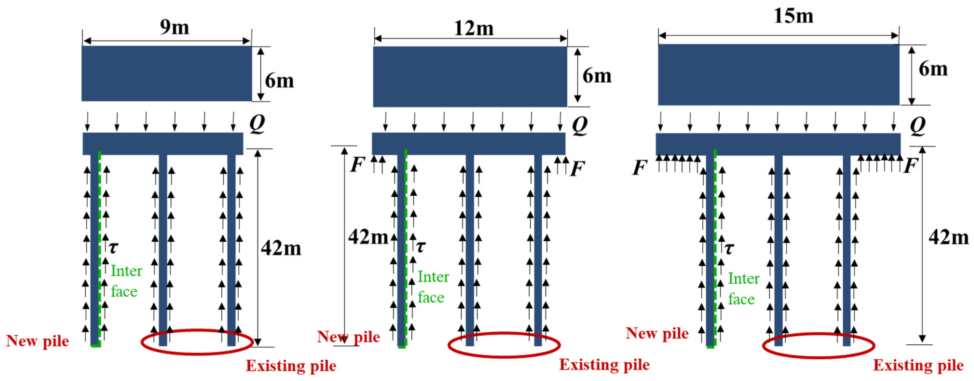
The pile cap acts as a link connecting upper loads, considering the design of new piles under loading conditions, larger or smaller pile cap configurations can induce variations in the deflection patterns of new and existing piles, thereby altering the interaction between new piles soil and existing piles. Three pile caps are designed, as shown in Figure 15. Under the same applied load in double pile models with different L/B, the settlement results of new and existing piles are depicted in Figure 16.
Figure 16 illustrates a consistent trend of reduced settlement variations of new and existing piles under different pile caps, indicating that pile caps, as stiff connectors, with larger areas providing greater area and stiffness, facilitate uniform transfer of upper loads to both new and existing piles, thereby reducing the loads borne by each pile. Concurrently, the load at both sides of the pile cap is supported by the underlying soil. It can be observed that whether at the pile head or pile bottom, for L/B > 4:2, settlement between the new pile and the existing pile remains stable. A similar settlement difference, then a stable difference between the new and existing piles with different L/B, indicates that under the same uniform load distribution, the settlement of the pile caused by changes in the pile cap remains limited and relatively stable.

5.3. Soil Layer Properties

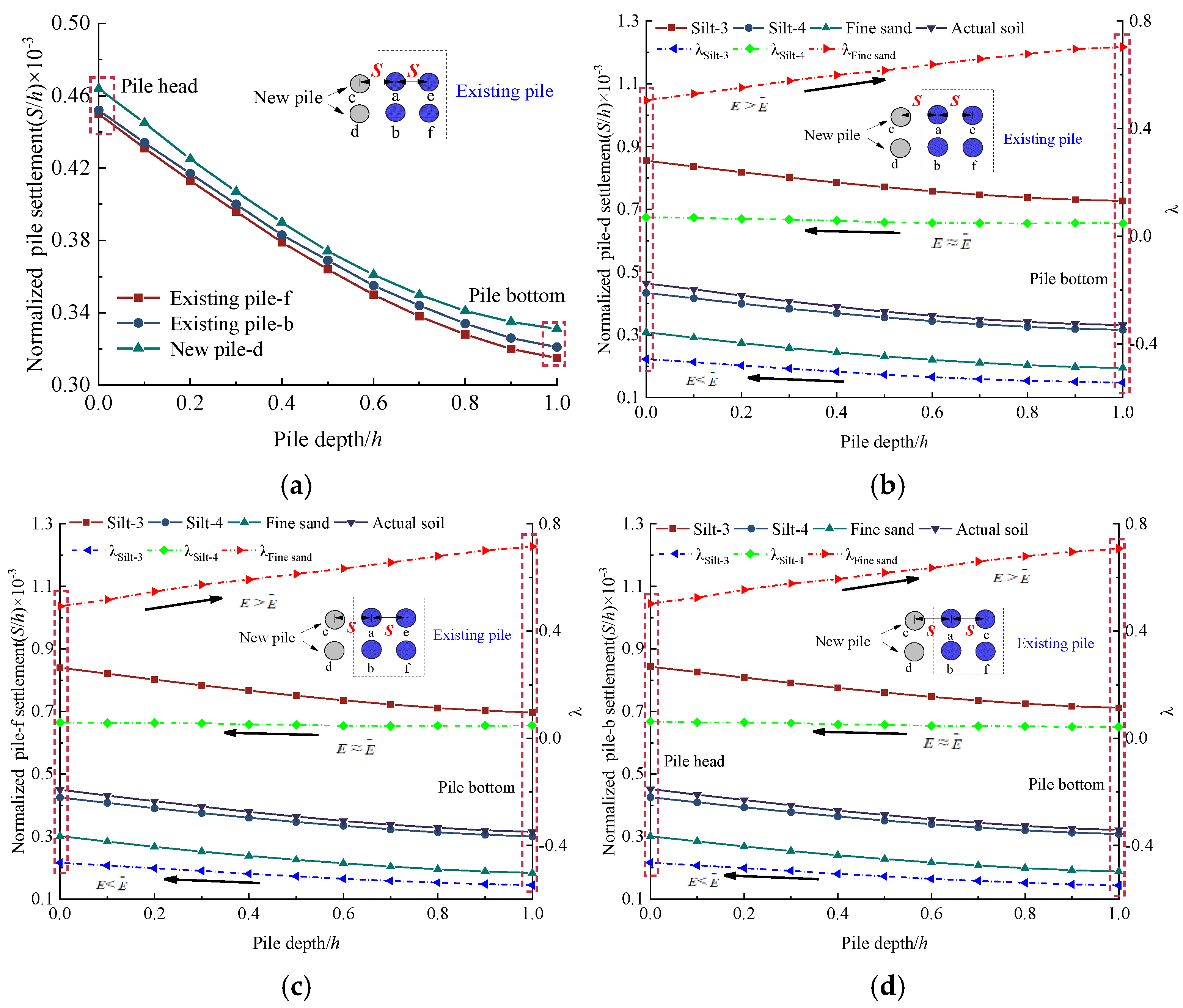
Single-layer soil models with different properties were established: silty soil with E1 = 6.5 MPa (E < Ea, Ea is the average elastic modulus of the original formation, 11.83 MPa) and E2 = 13.8 MPa (EEa), and sandy soil with E3 = 23 MPa (E > Ea). The settlement results of new and existing piles under different models, all with a pile length of 42 m, are shown in Figure 17. λ is defined to represent the ratio of the settlement differences between new and existing piles in the three soil layers compared to the actual conditions, which reflects the degree of settlement variation caused by soil layer deformation.
λ = S d S e S e
where Se is the settlement value of the pile in the single-layer soil model, and Sd is the settlement value of the new or existing piles under actual conditions.
Figure 17 shows a similar trend of pile settlement under different soil layers. Compared to the actual soil layers, the settlement results of new and existing piles under single-layer soils are closely related to E. In Figure 17b, the settlement of new piles decreases gradually with increasing pile depth in different soil models, and greater E of the soil layer is due to the smaller pile settlement result. When E < Ea, the settlement difference at the pile head is smaller than at the pile bottom.
For existing pile f and pile b, the settlement decreases gradually with increasing pile depth, consistent with the settlement pattern of new piles. In the silty soil-1 model (E < Ea), the settlement of new and existing piles under single-layer soil is greater than that under actual soil layers, with a stable value of λ approximately 0.7%. In the sandy soil model (E > Ea), the settlement of new and existing piles under single-layer soil is smaller than that under actual soil layers. In the silty soil-2 model (EEa), the settlement of new and existing piles under single-layer soil is similar to actual soil layers.

6. Discussion

A new parameter, existing pile efficiency (η), using the difference in settlement of existing piles with or without new piles as the settlement efficiency, is defined based on influence factors to quantify the mutual influence between existing and new piles. However, the efficiency of existing piles is influenced by many factors related to many factor parameters in this study. Therefore, further analysis focuses on proposing a general new pile design method based on η.
η = S S 0 S 0
where S is the settlement value of the existing pile after the establishment of new piles, S0 is the settlement value of the existing pile without new piles.

6.1. New Pile Parameters and Existing Pile Efficiency

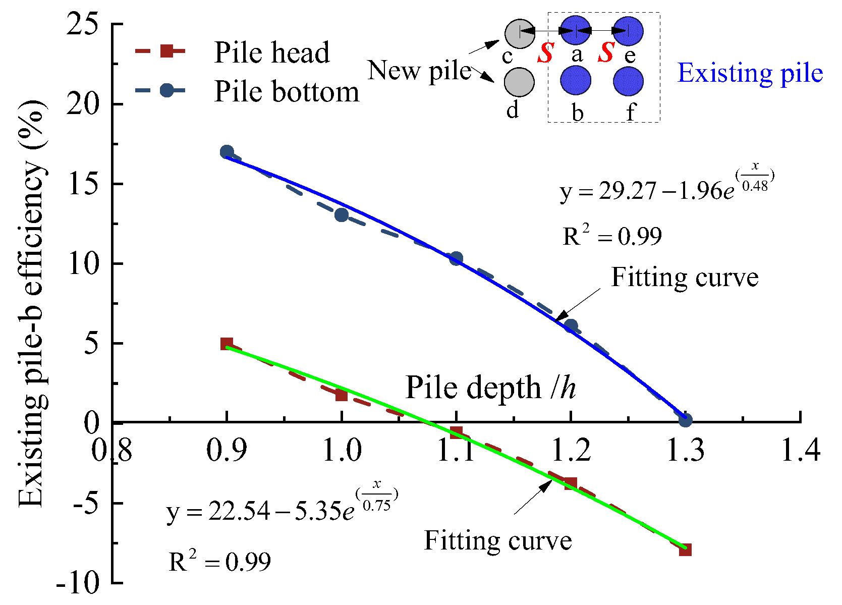
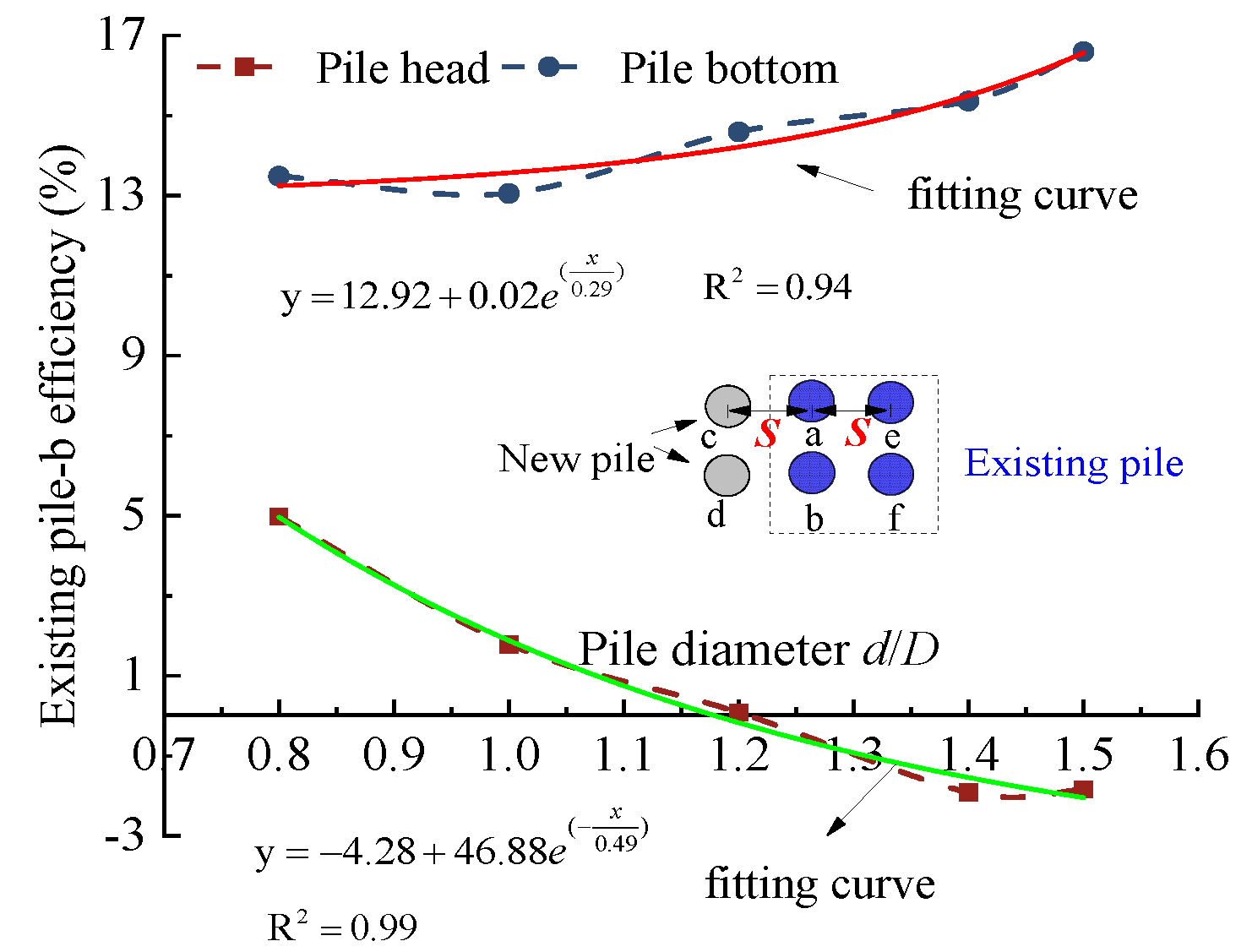
The performance efficiency of existing piles under the influence of new pile parameters. The study object is the settlement of existing piles under different parameters of new piles, involving pile head and pile bottom displacements of 0.8d, 1.0d, 1.2d, 1.4d, 1.5d, and 0.9h, 1.0h, 1.1h, 1.2h, 1.3h. Figure 18 and Figure 19 show the η under different hN(s) and dN(s) after the establishment of new piles. As shown, with the increase in hN and dN, the settlement of the existing pile under piles groups exhibits exponential changes, indicating a threshold effect of new piles on the existing piles. Based on the efficiency results of the pile head, it is recommended that the maximum hN and dN be selected within the range of 1.0–1.1h and 1.0–1.2d, respectively.

6.2. External Factors and Existing Pile Efficiency

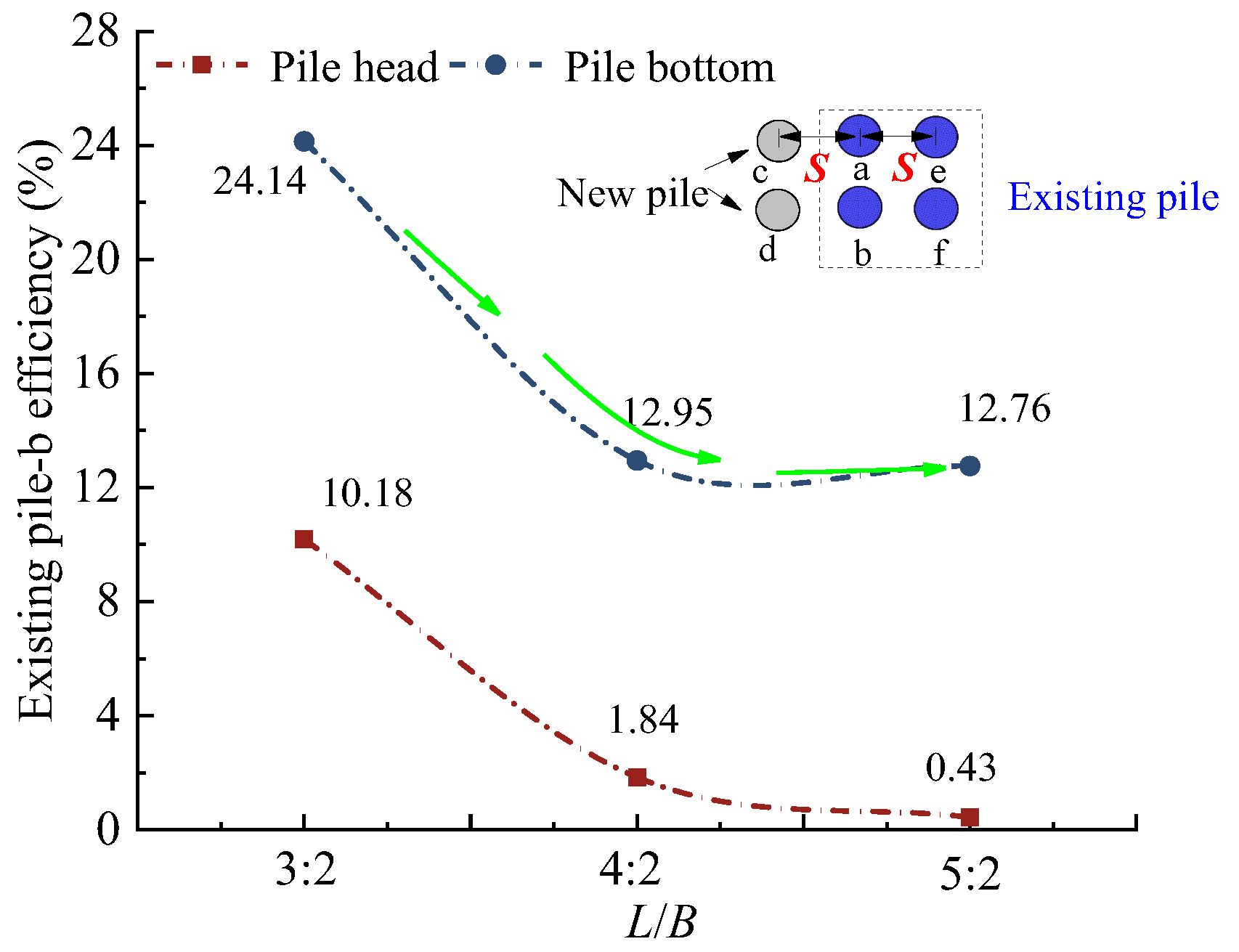
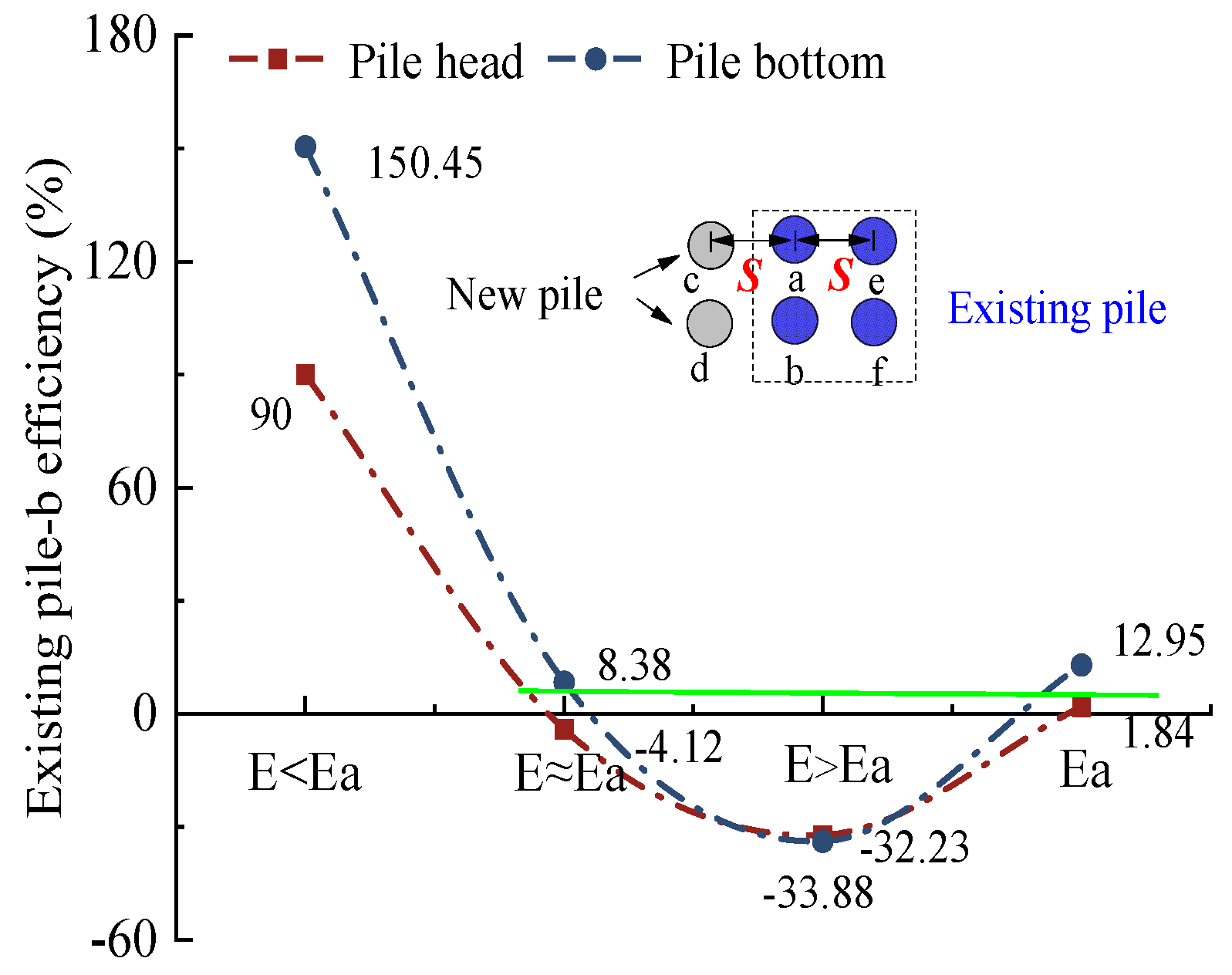
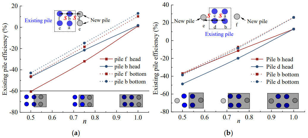
The pile arrangement, L/B, the eccentricity of load, and soil properties all affect pile settlement according to Equation (4). After the establishment of new piles, the contribution efficiency results of the pile cap on the settlement of the existing piles are shown in Figure 20. The difference between pile head and bottom remains stable with different L/B, and when L/B is 5:2, the pile cap size has the least influence on existing piles, but at 4:2, the influence already tends to stabilize. The settlement of the existing piles before and after the establishment of new piles shows significant changes in different soil layers, as shown in Figure 21, including the settlement differences between the pile head and bottom. When the E is too large or too small, the contribution rates differ significantly. When E < Ea, the establishment of new piles significantly affects the settlement of existing piles, with the pile head and bottom settlement of existing piles reaching 90% and 150.45%, respectively, under the influence of the efficiency of new piles. Figure 22 shows the settlement contribution efficiency of different pile arrangements on the existing piles after the establishment of new piles. The distance between the pile head and bottom in a symmetrical pile distribution is smaller than that in a lateral arrangement. When the load is evenly distributed on the pile cap, the settlement of the existing pile under symmetrical distribution reaches 2.75% and 13.33% at the pile head and bottom, respectively; the settlement reaches 1.10% and 10.26% at the pile head and bottom, respectively, in a lateral arrangement.
Based on the parameterized results, the contribution of new piles to the settlement response of existing piles can be quantified using the existing pile efficiency method.
From Table 3, it can be seen that, when the geometric parameters of new and existing piles are consistent, the influence of soil and load changes on the settlement of the existing piles is significant. Among the load factors, the settlement variation in symmetrical pile distribution is more stable than in lateral pile arrangement. The impact of pile cap changes on the settlement of existing piles is relatively smaller compared to other factors. Sorting the influence effects by settlement degree, the results show that after the installation of new piles, the most significant contribution to the settlement of the existing piles is due to soil changes, followed by the load on the pile cap, hN, dN, and pile cap L/B. After determining the soil relationship, necessary load eccentricity tests should be conducted in the analysis of mutual influences between new and existing piles. Based on the new pile parameters obtained in this study, it is reasonable to determine the hN in the range of 1.0–1.1h and the dN in the range of 1.0–1.2d. However, from the pile head and bottom data of the soil layer, when the soil layer remains a single layer with different E, there is still a certain difference between the pile head and bottom. This difference indicates the role of pile-side friction. Under the same soil layer, the settlement contribution of the existing pile is more significant in soil layers with low E.
This study has demonstrated the potential of utilizing existing piles to support new structures while reinforcing them with complementary piles. The numerical model was calibrated using established geotechnical parameters and validated against static load test data, confirming its reliability for settlement analysis. However, to further strengthen the scientific impact of the findings, future research should incorporate full-scale experimental validation to compare ultimate load-bearing capacity and settlement predictions with real projects.

7. Conclusions

A series of investigations on the interaction between new piles, soil, and existing piles were conducted to elucidate the settlement behavior of existing piles influenced by new pile installation. The main conclusions are as follows:
  • The settlement of new piles decreases exponentially with increasing pile spacing (dN). As dN increases, the settlement in the upper half of both new and adjacent existing piles decreases, while settlement in the lower half increases. The settlement behavior of new and nearby existing piles exhibits significant segmented characteristics as dN varies.
  • The installation of new piles induces bidirectional displacement in existing piles. To minimize this impact, it is recommended to select dN and hN within the ranges of 1.0–1.1h and 1.0–1.2d, respectively.
  • Compared to symmetrical arrangements, lateral arrangements of new and existing piles demonstrate slightly greater stability in settlement behavior under varying load distributions, making them a preferable design choice for certain loading scenarios.
  • Besides pile height and diameter, pile caps exhibit a size effect on the settlement behavior of new and existing piles. When the cap ratio (L/B) is approximately 4:2, the settlement difference between new and existing piles tends to stabilize.
  • An existing pile efficiency parameter (η) is introduced, and sensitivity analysis reveals that the most significant factors affecting the settlement behavior are geological properties, load distribution, pile arrangement, hN, dN and L/B, in that order. This parameter provides a practical approach to assessing pile interactions.

Author Contributions

J.N.: Conceptualization, Software, Writing—Original draft preparation; Z.Y.: Funding acquisition, Writing—Review and Editing; S.Y.: Validation, Supervision, Software, Investigation, Data analysis; S.C.: Writing—Reviewing and Editing, Resources. All authors have read and agreed to the published version of the manuscript.

Funding

This work was funded by the China Construction Seventh Engineering Division Co., Ltd. (No. 20220838).

Institutional Review Board Statement

Not applicable.

Informed Consent Statement

Not applicable.

Data Availability Statement

Dataset available upon request from the authors.

Acknowledgments

The authors gratefully acknowledge financial support from the China Scholarship Council.

Conflicts of Interest

Author Jingsen Niu and Shengzhao Cheng were employed by the company Installation Engineering Co., Ltd. and China Construction Seventh Engineering Division, Co., Ltd. The remaining authors declare that the research was conducted in the absence of any commercial or financial relationships that could be construed as a potential conflict of interest. The authors declare that this study received funding from the China Construction Seventh Engineering Division Co., Ltd. The funder was not involved in the study design, collection, analysis, interpretation of data, the writing of this article or the decision to submit it for publication.

References

  1. Chow, Y.K.; Thevendran, V. Optimisation of pile groups. Comput. Geotech. 1987, 4, 43–58. [Google Scholar] [CrossRef]
  2. Cao, M.; Chen, L. Analysis of interaction factors between two piles. J. Shanghai Jiaotong Univ. 2008, 13, 171–176. [Google Scholar] [CrossRef]
  3. Kim, Y.; Jeong, S. Analysis of soil resistance on laterally loaded piles based on 3D soil–pile interaction. Comput. Geotech. 2011, 38, 248–257. [Google Scholar] [CrossRef]
  4. Martin, C.M.; Randolph, M.F. Upper-bound analysis of lateral pile capacity in cohesive soil. Géotechnique 2006, 56, 141–145. [Google Scholar] [CrossRef]
  5. Livneh, B.; Naggar, M.E. Axial testing and numerical modeling of square shaft helical piles under compressive and tensile loading. Can. Geotech. J. 2008, 45, 1142–1155. [Google Scholar] [CrossRef]
  6. Elsherbiny, Z.H.; El Naggar, M.H. Axial compressive capacity of helical piles from field tests and numerical study. Can. Geotech. J. 2013, 50, 1191–1203. [Google Scholar] [CrossRef]
  7. Lueprasert, P.; Jongpradist, P.; Jongpradist, P.; Schweiger, H.F. Structural Responses of a Tunnel Lining Due to an Adjacent Loaded Pile. Int. J. Civ. Eng. 2023, 21, 1027–1043. [Google Scholar] [CrossRef]
  8. Butcher, A.P.; Powell, J.J.M.; Skiner, H.D. Reuse of Foundations for Urban Sites: A Best Practice Handbook; BRE Press: Watford, UK, 2006. [Google Scholar]
  9. Tamura, S.; Adachi, K.; Sakamoto, T.; Hida, T.; Hayashi, Y. Effects of existing piles on lateral resistance of new piles. Soils Found. 2012, 52, 381–392. [Google Scholar] [CrossRef]
  10. Brian, S. Numerical simulations of the reuse of piled raft foundations in clay. Acta Geotech. 2017, 12, 1047–1059. [Google Scholar] [CrossRef]
  11. Hertlein, B.H.; Walton, W.H. Assessment and Reuse of Old Foundations. Transp. Res. Rec. 2000, 1736, 48–52. [Google Scholar] [CrossRef]
  12. Leung, Y.F.; Leung, Y.F.; Soga, K.; Klar, A. Multi-objective foundation optimization and its application to pile reuse. In Proceedings of the Geo-Frontiers 2011, Dallas, TX, USA, 13–16 March 2011; pp. 75–84. [Google Scholar] [CrossRef]
  13. Horii, Y.; Nagao, T.; Kawata, M.; Ishizawa, S.; Ono, S. Reuse of existing piles using flexible connection at pile head. J. Archit. Build. Sci. AIJ 2007, 13, 81–84. (In Japanese) [Google Scholar] [CrossRef]
  14. Watanabe, T.; Ishizaki, S.; Tomita, N.; Kawamoto, S.; Tatsuno, S. Reuse of existing bored piles for high-rise building foundation. Jpn. Geotech. Soc. Spec. Publ. 2015, 2, 158–161. [Google Scholar] [CrossRef]
  15. Li, L.; Li, J.P.; Sun, D.A.; Gong, W.B. Analysis of time-dependent bearing capacity of a driven pile in clayey soils by total stress method. Int. J. Geomech. 2017, 17, 04016156. [Google Scholar] [CrossRef]
  16. Augustesen, A.H. The Effects of Time on Soil Behaviour and Pile Capacity. Ph.D. Thesis, Aalborg University, Aalborg, Denmark, 2006. [Google Scholar]
  17. Roy, M.; Blanchet, R.; Tavenas, F.; La Rochelle, P. Behaviour of a sensitive clay during pile driving. Can. Geotech. J. 1981, 18, 67–85. [Google Scholar] [CrossRef]
  18. Poulos, H.G. Effect of pile driving on adjacent piles in clay. Can. Geotech. J. 1994, 31, 856–867. [Google Scholar] [CrossRef]
  19. Li, L.; Gong, W. Prediction of nonlinear vertical settlement of a pile group consisting of new and existing displacement piles in clay strata. Soils Found. 2019, 59, 1336–1348. [Google Scholar] [CrossRef]
  20. Reda, A.; Amaechi, C.V.; Shahin, M.A. Case study for effects of pile installation on existing offshore facilities in brownfields. Appl. Ocean Res. 2023, 138, 103651. [Google Scholar] [CrossRef]
  21. Shan, H.; Xia, T.; Yu, F.; Tao, H.; He, S.; Giosuè, B.; Boscato, G. Influence of Underpinning Pile Drilling Construction on the Bearing Behavior of Existing Loaded Foundation Piles: Case Study. Adv. Civ. Eng. 2020, 2020, 9568279. [Google Scholar] [CrossRef]
  22. Zhou, P.; Liu, H.L.; Zhou, H.; Cao, G.W.; Ding, X.M. A simplified analysis approach for the effect of the installation of adjacent XCC pile on the existing single XCC pile in undrained clay. Acta Geotech. 2022, 17, 5499–5519. [Google Scholar] [CrossRef]
  23. Wu, W.; Yang, Z.; Liu, X.; Zhang, Y.; Liu, H.; El Naggar, M.H.; Xu, M.; Mei, G. Horizontal dynamic response of pile in unsaturated soil considering its construction disturbance effect. Ocean Eng. 2022, 245, 110483. [Google Scholar] [CrossRef]
  24. Begaj, L.; McNamara, A.M. Centrifuge model testing for pile foundation reuse. Int. J. Phys. Model. Geotech. 2011, 11, 166–177. [Google Scholar] [CrossRef]
  25. Tamura, S.; Higuchi, Y.; Hayashi, Y.; Yamzasaki, M. Centrifuge studies on the effects of existing piles on the end resistance and shaft friction of a new pile. Soils Found. 2012, 52, 1062–1072. [Google Scholar] [CrossRef]
  26. Li, H.; Tamura, S. An existing pile efficiency method for the design of lateral new pile behavior in sites with existing piles. Can. Geotech. J. 2023, 60, 1188–1201. [Google Scholar] [CrossRef]
  27. Li, H.; Liu, S.; Tong, L.; Zhang, D. Influence of the head fixity adjustment of existing piles on the lateral load response of new piles. Géotechnique 2023, 75, 56–67. [Google Scholar] [CrossRef]
  28. Zhou, J.; Li, G.; Liu, L.; Li, Y.; Nie, Y. Investigation of the Load-Settlement Response of Piles in Sand Using an Interface Constitutive Model. Int. J. Geomech. 2022, 22, 04022198. [Google Scholar] [CrossRef]
  29. Huang, M.; Zhang, C.; Li, Z. A simplified analysis method for the influence of tunneling on grouped piles. Tunn. Undergr. Space Technol. 2009, 24, 410–422. [Google Scholar] [CrossRef]
  30. Jawad, S.; Han, J. Numerical Analysis of Laterally Loaded Single Free-Headed Piles within Mechanically Stabilized Earth Walls. Int. J. Géoméch. 2021, 21, 04021038. [Google Scholar] [CrossRef]
  31. Tomlinson, M.; Woodward, J. Pile Design and Construction Practise, 5th ed.; Taylor & Francis Group: London, UK; New York, NY, USA, 2007. [Google Scholar]
  32. Cook, R.D.; Malkus, D.S.; Plesha, M.E.; Witt, R.J. Concept and Applications of Finite Elements Analysis, 4th ed.; John Wiley & Sons, Inc.: Hoboken, NJ, USA, 2001. [Google Scholar]
  33. Li, Z.; Chen, Z.; Wang, L.; Zeng, Z.; Gu, D. Numerical simulation and analysis of the pile underpinning technology used in shield tunnel crossings on bridge pile foundations. Undergr. Space 2021, 6, 396–408. [Google Scholar] [CrossRef]
  34. Gu, X.; Chen, F.; Zhang, W.; Wang, Q.; Liu, H. Numerical investigation of pile responses induced by adjacent tunnel excavation in spatially variable clays. Undergr. Space 2022, 7, 911–927. [Google Scholar] [CrossRef]
  35. Liu, X.Z.; Sang, Y.L.; Zhao, F.; Shi, G.; Heng, Y. Evaluation of effects of static pile driving on existing metro tunnel structure. J. Perform. Constr. Facil. 2019, 33, 04019045. [Google Scholar] [CrossRef]
  36. Deb, P.; Debnath, B.; Reang, R.B.; Pal, S.K. Structural analysis of piled raft foundation in soft soil: An exp erimental simulation and parametric study with numerical method. Ocean Eng. 2022, 261, 112139. [Google Scholar] [CrossRef]
  37. Chen, Y.; Xu, D. FLAC/FLAC3D Foundation and Engineering Example; China Water Resources and Hydropower Press: Beijing, China, 2009. [Google Scholar]
  38. Liu, H.; Gu, S.; Duan, S.; Hou, S. Load Settlement Response of Composite Foundation of Variable Pile Diameters. Int. J. Geomech. 2024, 24, 04024202. [Google Scholar] [CrossRef]
  39. Li, L.; Gong, W.B.; Li, J.P. Effects of clay creep on long-term load-carrying behaviors of bored piles: Aiming at reusing existing bored piles. Int. J. Geomech. 2020, 20, 04020132. [Google Scholar] [CrossRef]
  40. Randolph, M.F.; Carter, J.P.; Wroth, C.P. Driven piles in clay—The effects of installation and subsequent consolidation. Géotechnique 1979, 29, 361–393. [Google Scholar] [CrossRef]
  41. Bond, A.J.; Jardine, R.J. Effects of installing displacement piles in a high OCR clay. Géotechnique 1991, 41, 341–363. [Google Scholar] [CrossRef]
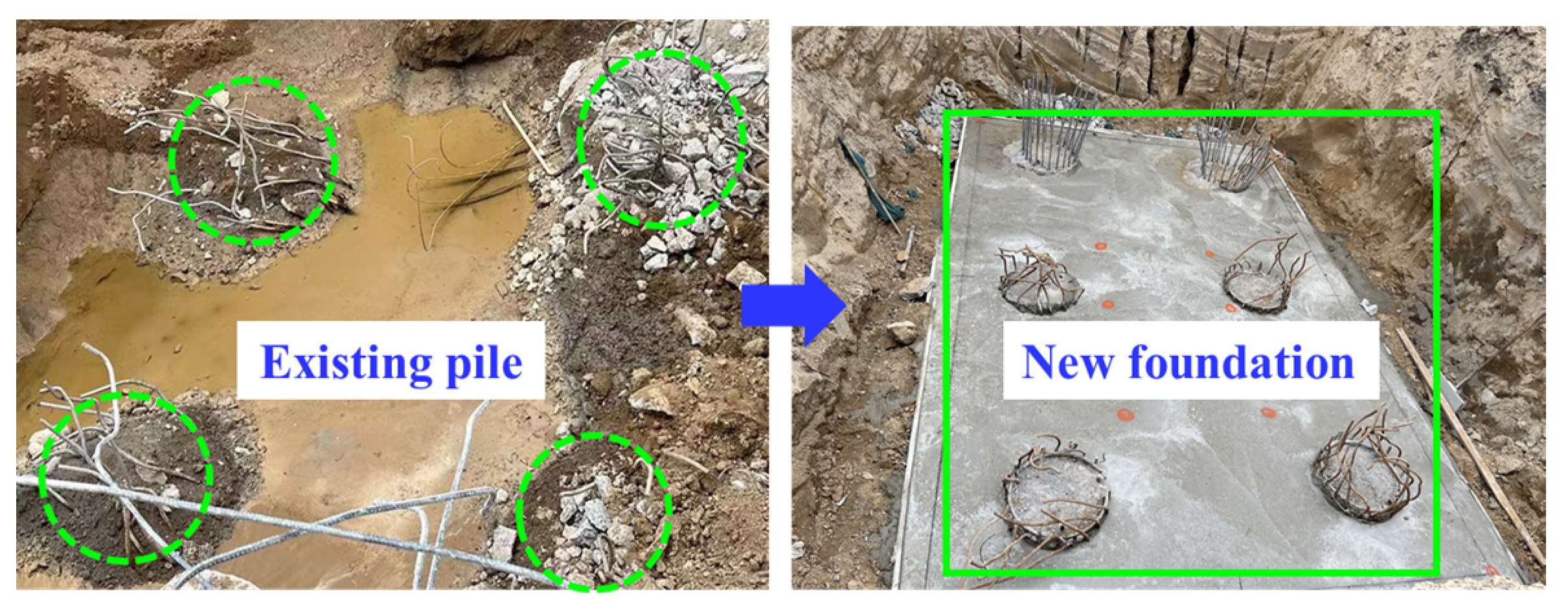
Figure 1. Reconstruction construction.
Applsci 15 03016 g001
Figure 2. Pile-soil-pile interaction in the pile group foundation.
Applsci 15 03016 g002
Figure 3. Three-dimensional numerical simulation model.
Applsci 15 03016 g003
Figure 4. Determination of the smallest width of the adjoining zone.
Applsci 15 03016 g004
Figure 5. Simulation process: (a) ground stress balance; (b) apply existing piles; (c) dismantle the load of the existing pile head; (d) apply new piles and add pile cap; (e) load the pile cap; (f) monitoring the displacement and stress of the piles.
Applsci 15 03016 g005
Figure 6. Verification of numerical simulation result.
Applsci 15 03016 g006
Figure 7. Displacement contour of new and existing piles with different pile parameters: (a) displacement contour of new and existing piles with dN(s); (b) displacement contour of new and existing piles with hN(s).
Applsci 15 03016 g007aApplsci 15 03016 g007b
Figure 8. Relationship between new pile settlement and hN(s).
Applsci 15 03016 g008
Figure 9. Relationship between new pile settlement and dN(s).
Applsci 15 03016 g009
Figure 10. Relationship between settlement of existing pile foundations and hN(s): (a) existing pile (pile-f); (b) existing pile (pile-b).
Applsci 15 03016 g010
Figure 11. Relationship between settlement of existing piles and dN(s): (a) existing pile (pile-f); (b) existing pile (pile-b).
Applsci 15 03016 g011
Figure 12. Load distribution conditions of pile cap.
Applsci 15 03016 g012
Figure 13. Settlement of pile and arrangement of new and existing piles: (a) symmetric arrangement; (b) lateral arrangement.
Applsci 15 03016 g013
Figure 14. Stress distribution of pile under different loads: (a) symmetric arrangement; (b) lateral arrangement.
Applsci 15 03016 g014
Figure 15. Different pile caps (L/B) in the new and existing pile group system.
Applsci 15 03016 g015
Figure 16. Settlement of new and existing piles with different L/B: (a) existing pile (pile-f); (b) existing pile (pile-b); (c) existing pile (pile-d).
Applsci 15 03016 g016
Figure 17. Relationship between pile settlement and soil properties: (a) settlement of new and existing piles under actual soil layer; (b) settlement of new pile-d in different soil layers; (c) the settlement of existing pile-f in different soil layers; (d) settlement of existing pile-b in different soil layers.
Applsci 15 03016 g017
Figure 18. Relationship between η and hN.
Applsci 15 03016 g018
Figure 19. Relationship between η and dN.
Applsci 15 03016 g019
Figure 20. Relationship between η and L/B.
Applsci 15 03016 g020
Figure 21. Relationship between η and E.
Applsci 15 03016 g021
Figure 22. Relationship between η and load distribution: (a) symmetric arrangement; (b) lateral arrangement.
Applsci 15 03016 g022
Table 1. Soil parameters of the research area.
LayerDepth (m)c (kPa)ρ (kg/cm3)φ (°)E (Mpa)ν
Fill0.0–1.8518002550.35
Silt-11.8–11.012.6179220.110. 70.35
Silt-211.0–14.012.9173020.49.20.31
Silt-314.0–16.713.2176021.46.50.30
Silt sand16.7–21.70185025.016.00.25
Silt-421.7–28.114.1184721.813.80.30
Fine sand28.1–35.60185030.023.00.25
Silt clay35.6–42.433.8195813.38.50.34
Silt + clay42.4–51.015.2196022.514.50.31
Clay + silt51.0–60.033.5194713.311.00.31
Table 2. Material properties of piles for the numerical model.
ParameterValueDescription
New pile
(as dN = 1.2 m)
EI3.53 × 106Bending stiffness (kN·m2)
ν0.3Poisson’s ratio
Head condition-Restrained by pile cap
Existing pileEI1.47 × 106Bending stiffness (kN·m2)
ν0.3Poisson’s ratio
Head condition-Restrained by pile cap
Pile capE3.15 × 107Elastic modulus (kPa)
ν0.3Poisson’s ratio
Table 3. Contribution values of research factors to settlement response of existing piles.
Pile HeadPile Bottom Pile HeadPile Bottom
dN0.8~1.5d0.8~1.5dhN0.9~1.3h0.9~1.3h
4.98~−1.84%13.49~16.60%4.97~−7.92%17~0.20%
L/B9:6~15:69:6~15:6Soil layer0.56Ea~1.95Ea0.56Ea~1.95Ea
10.18~0.43%24.14~12.76%90~−32.23150.45~−33.88
Symmetric arrangement0.5~10.5~1Lateral arrangement0.5~10.5~1
−42.67~2.75−43.07~13.33−60.36~1.10−46.12~10.26
Disclaimer/Publisher’s Note: The statements, opinions and data contained in all publications are solely those of the individual author(s) and contributor(s) and not of MDPI and/or the editor(s). MDPI and/or the editor(s) disclaim responsibility for any injury to people or property resulting from any ideas, methods, instructions or products referred to in the content.