
Numerical Study on the Bending Performance of Steel-Ribbed Composite Slabs for Substations

 ,
,  and
and 
Abstract
1. Introduction
2. Design Scheme of Steel-Ribbed Composite Slabs
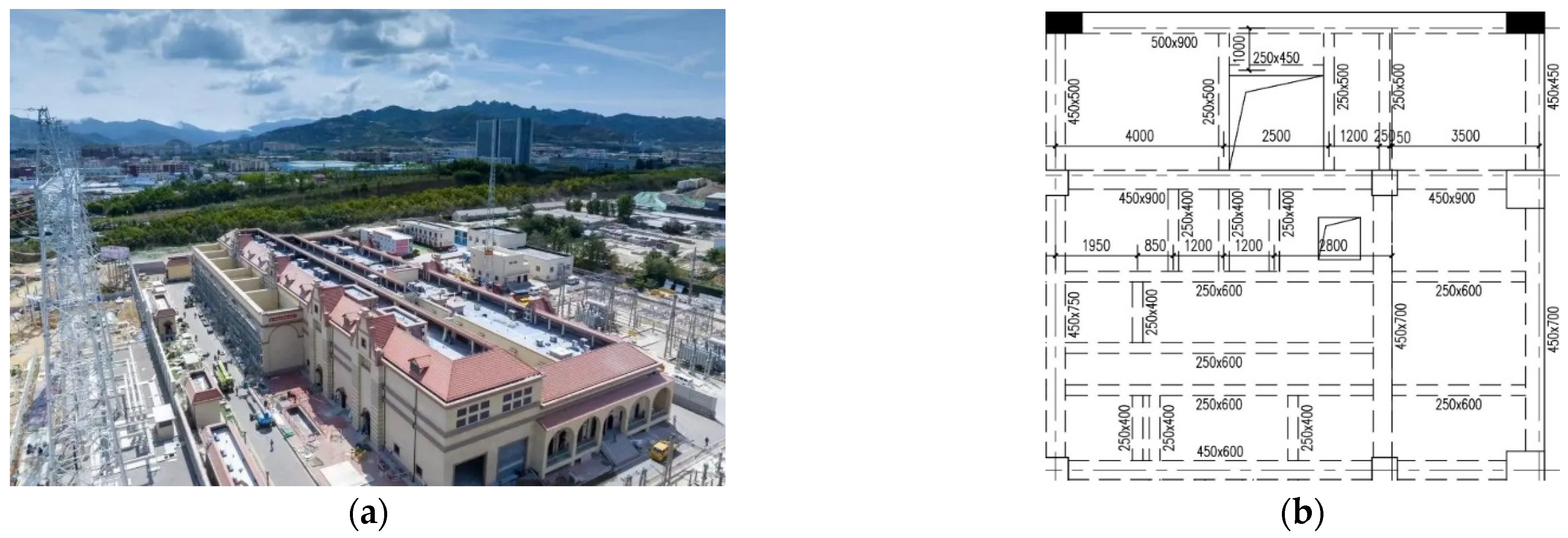
2.1. Project Background
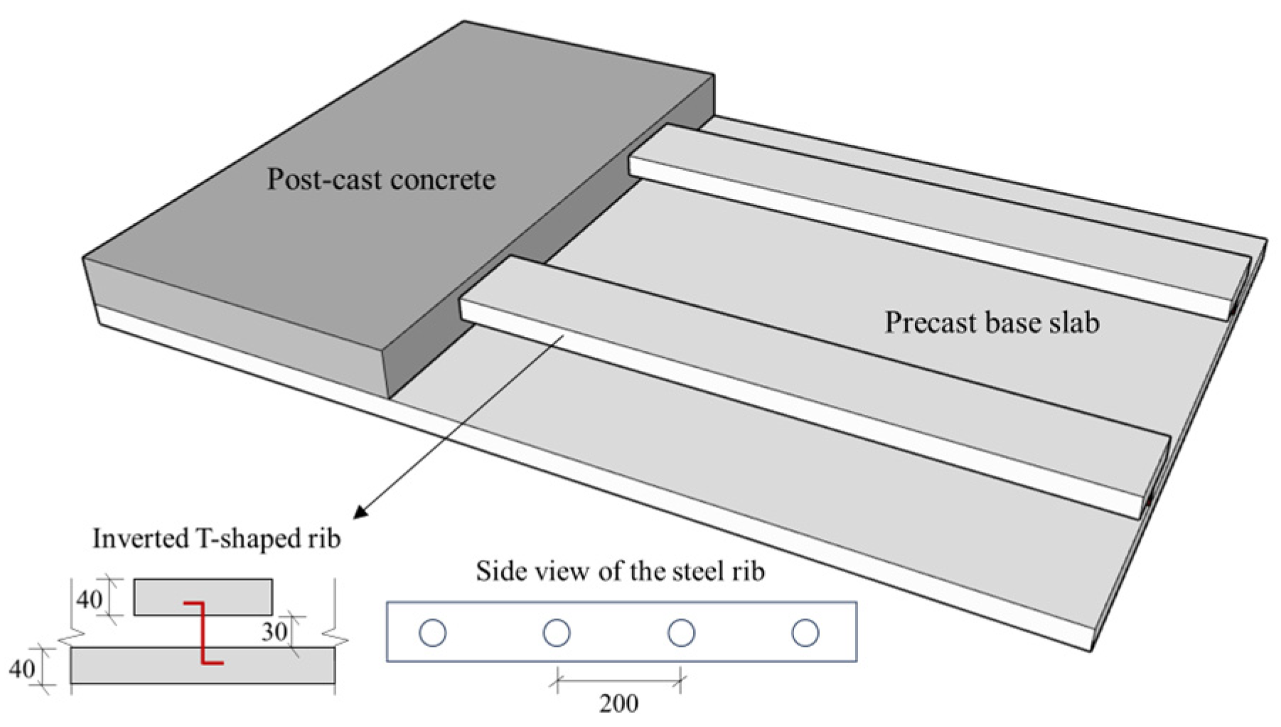
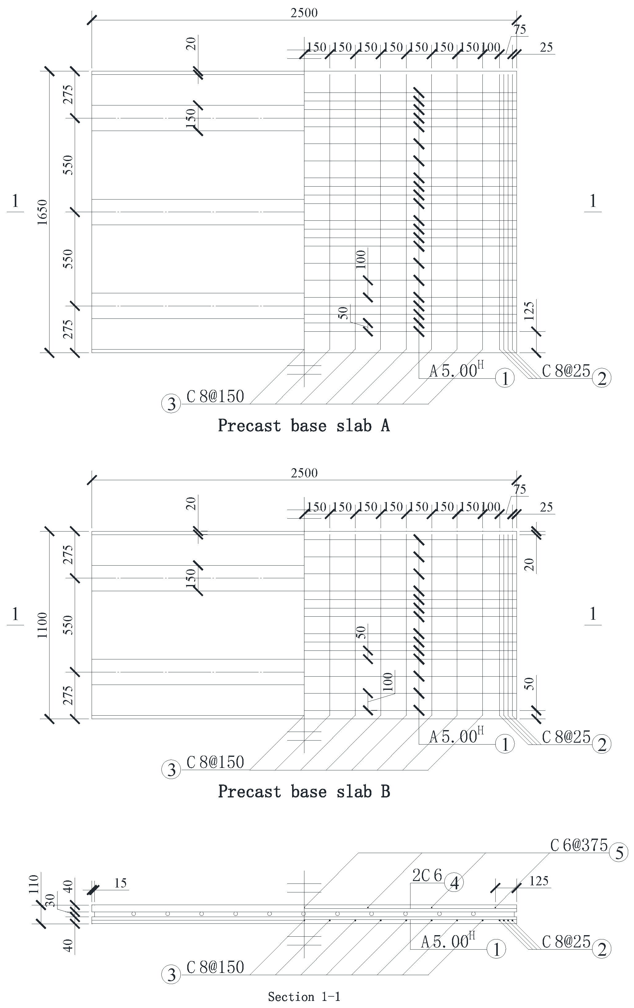
2.2. Design Parameters of Steel-Ribbed Composite Slabs
3. Finite Element Modeling
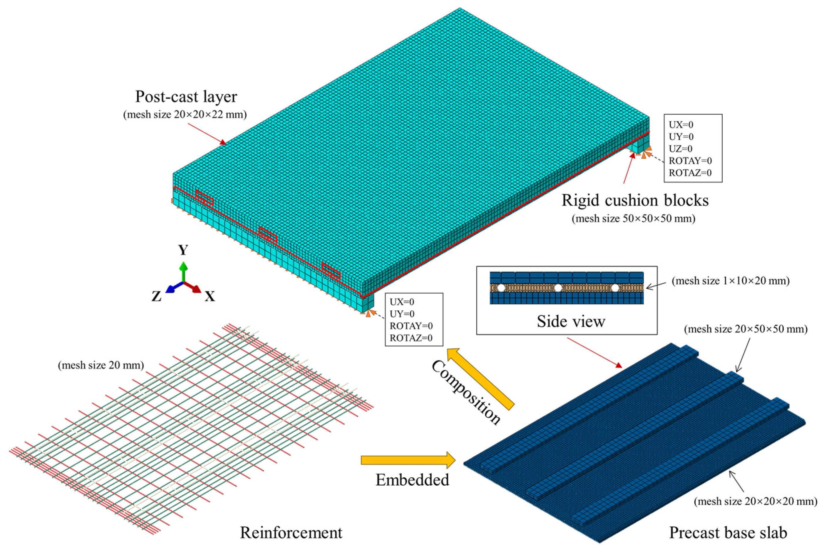
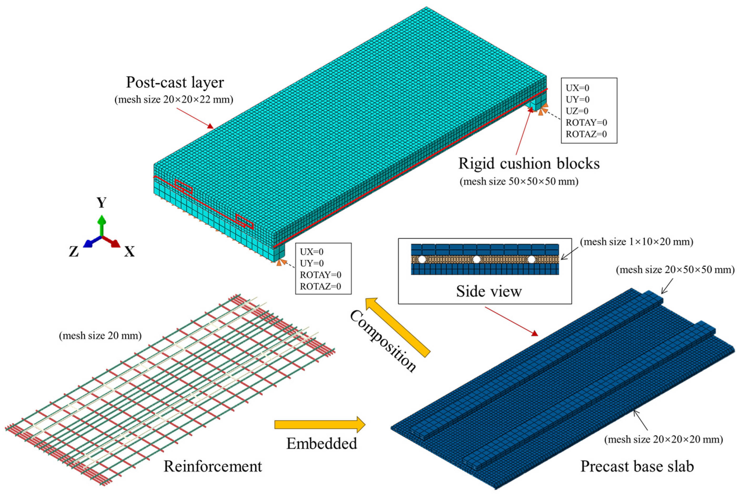
3.1. Basic Assumptions
- The materials are assumed to be isotropic and homogeneous;
- The relative slip between the laminated concrete layers is negligible, and the two layers work together.
- Perfect bonding is assumed between the concrete and steel (rebars, prestressing steels, and steel ribs) without any relative slip.
3.2. Establishment of Finite Element Models
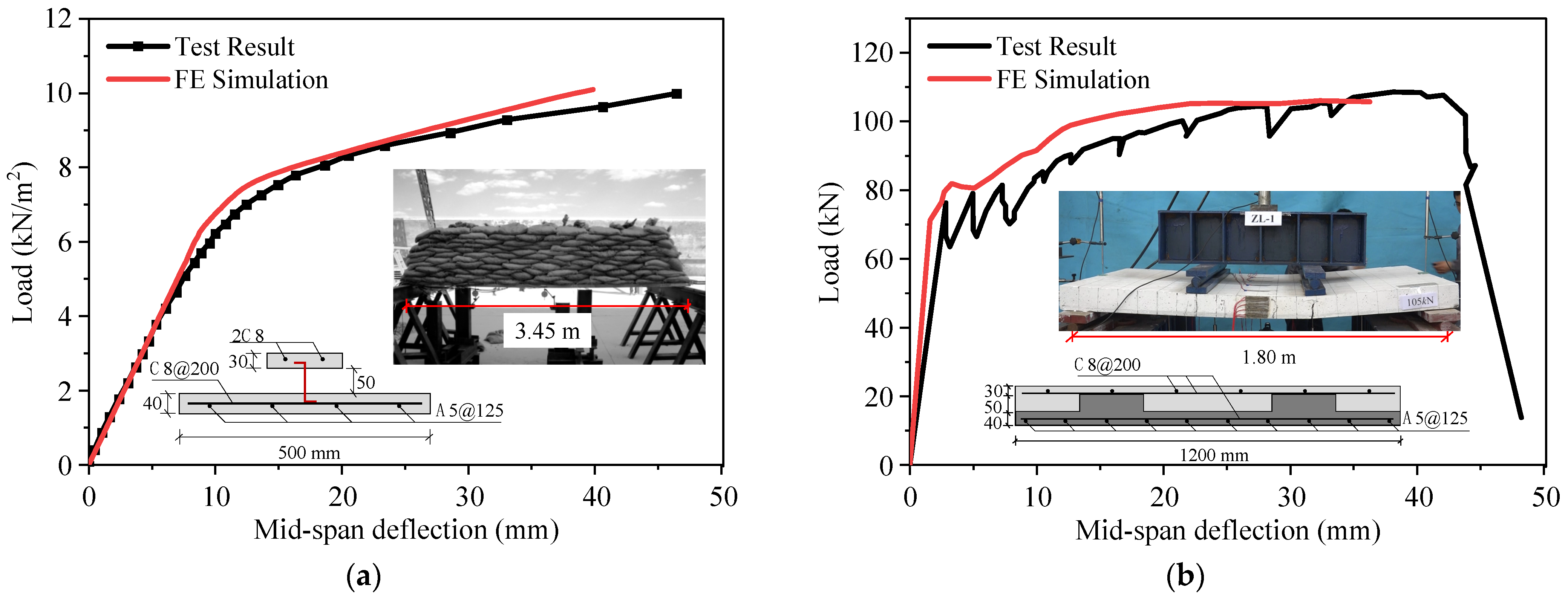
3.3. Validation of Finite Element Models
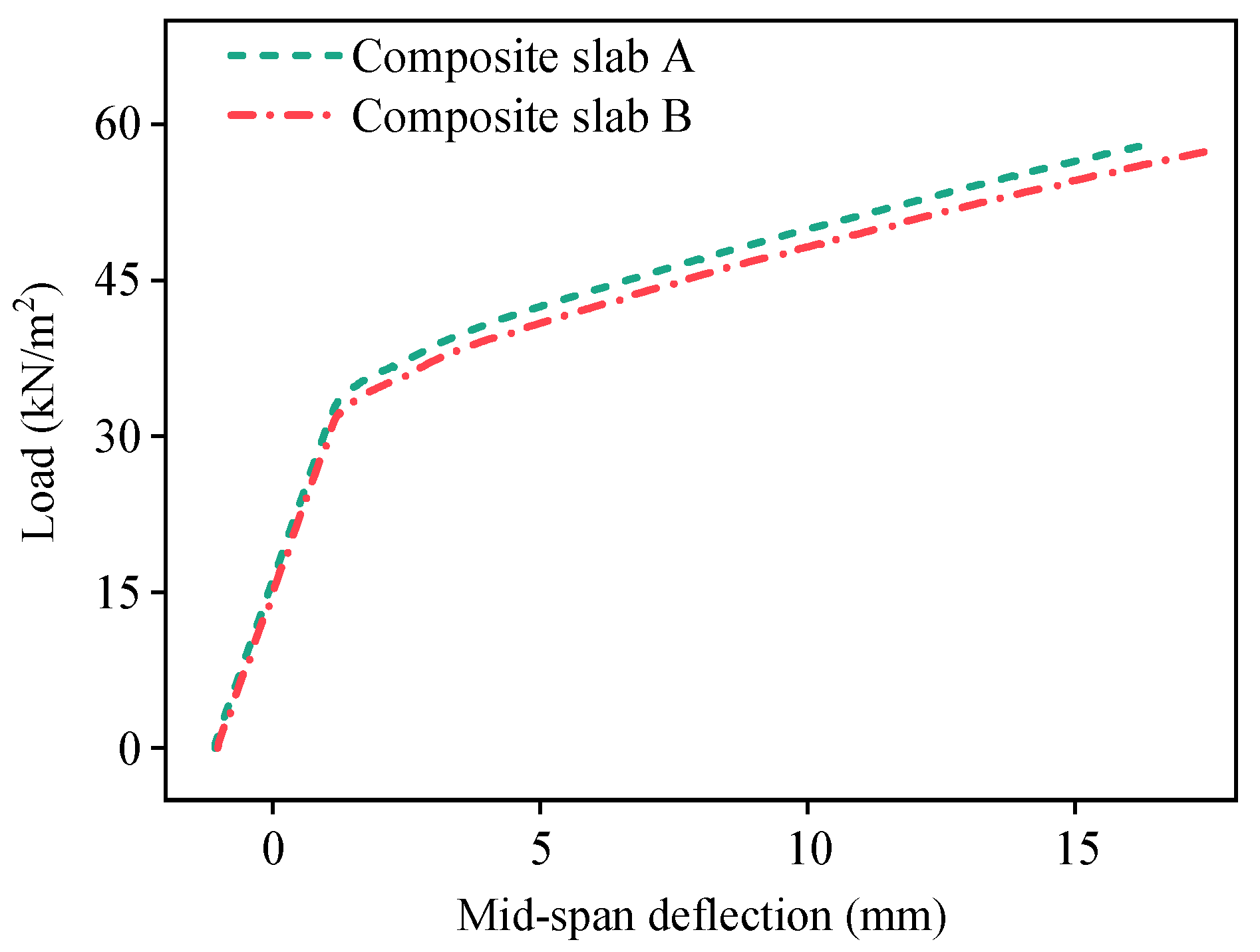
4. Unidirectional Bending Performance of Composite Slabs
4.1. Results of Composite Slab A
4.2. Results of Composite Slab B
4.3. Discussion of Results
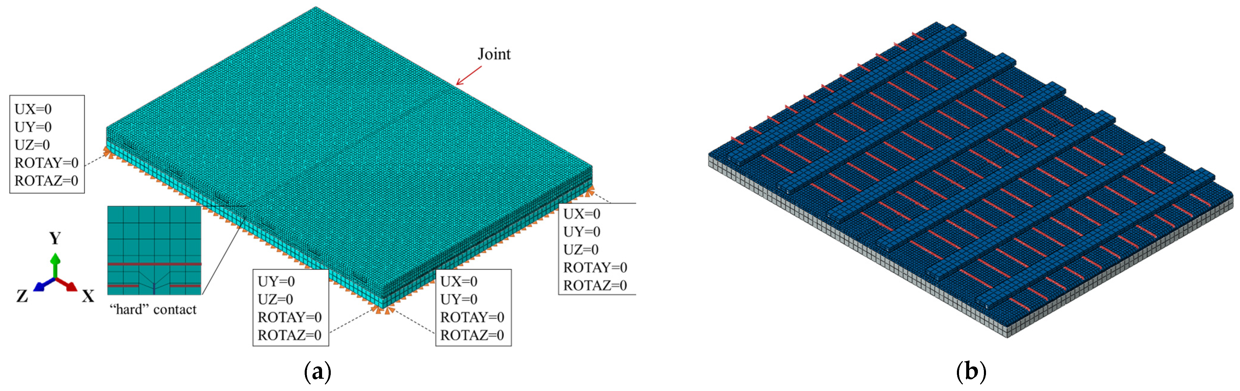
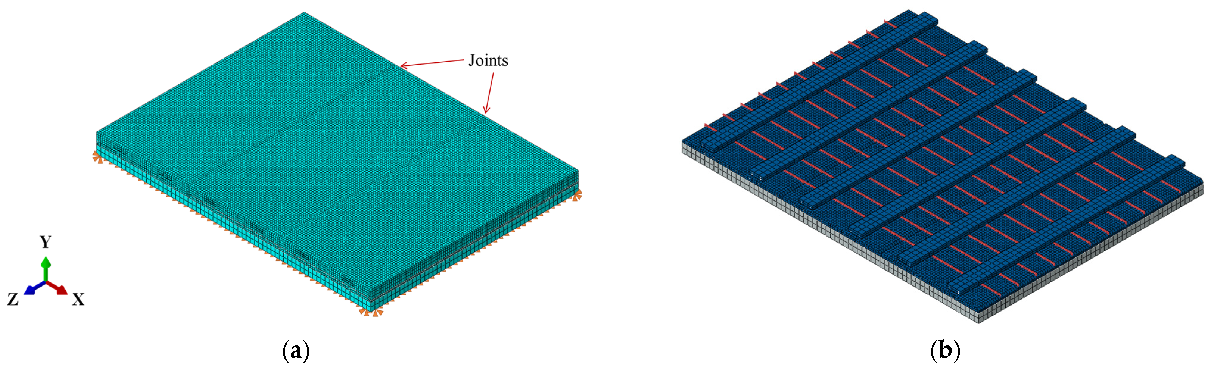
5. Bidirectional Bending Performance of Composite Slabs
5.1. Double-Spliced Composite Bidirectional Slab
5.2. Triple-Spliced Composite Bidirectional Slab
5.3. Cast-in-Place Monolithic Bidirectional Slab
5.4. Discussion of Results
6. Conclusions
- (1)
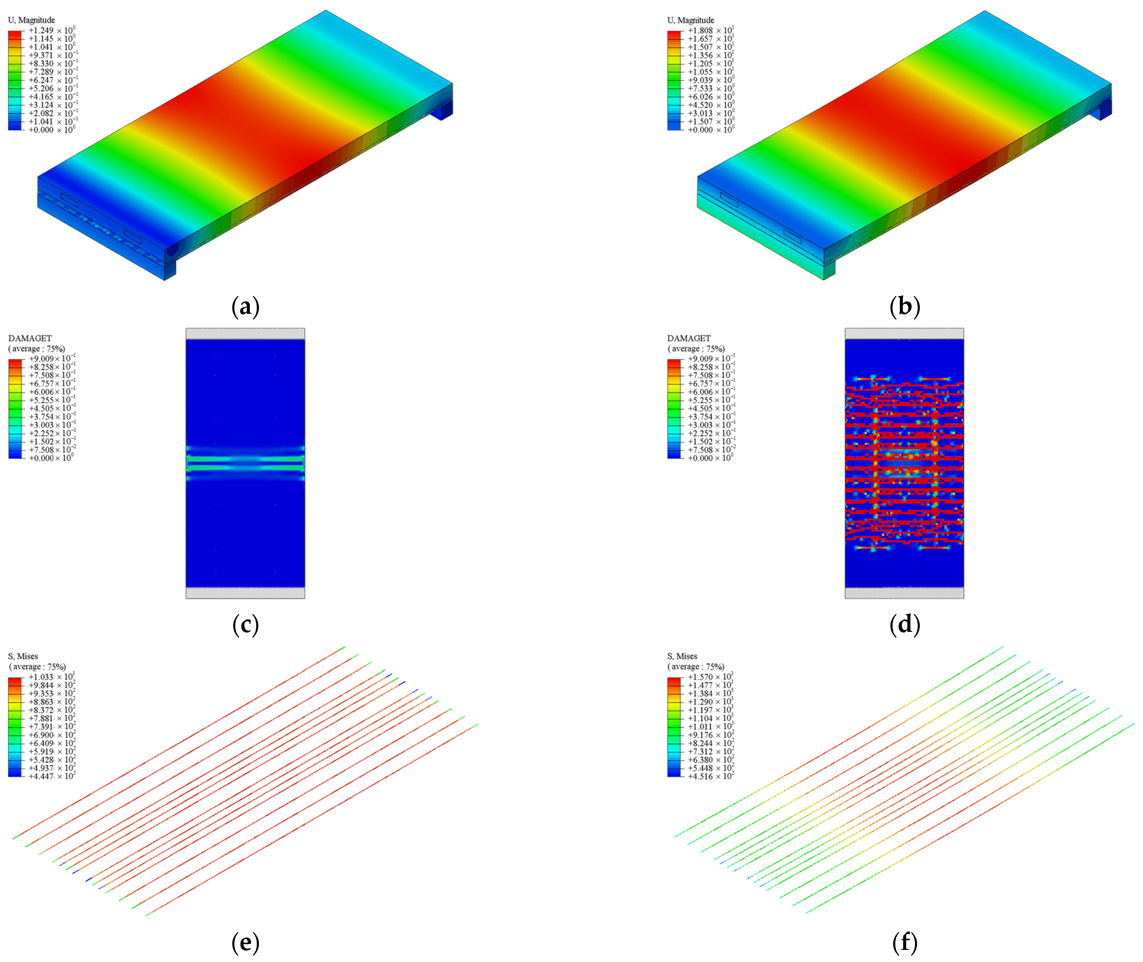
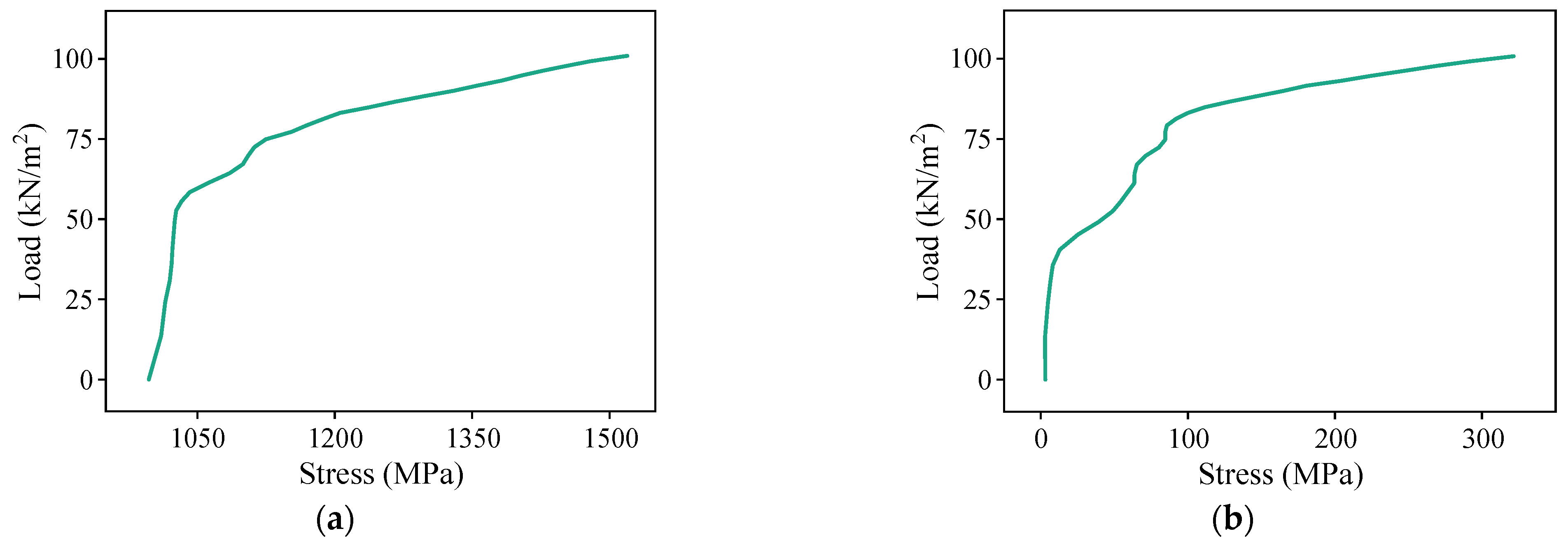
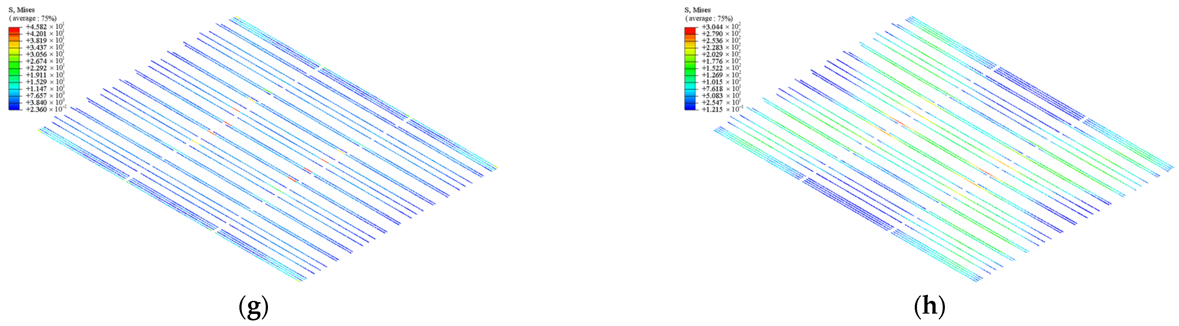
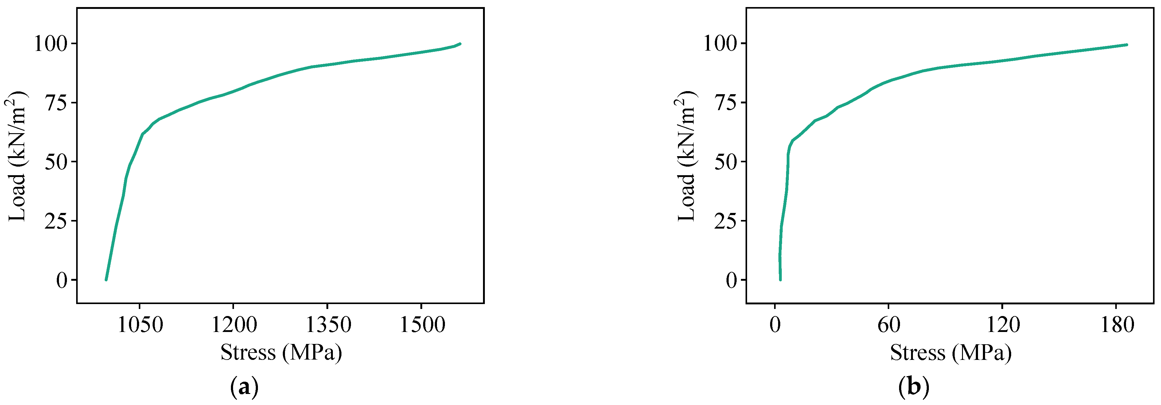
- For unidirectional bending performance, the designed composite slabs present typical two-stage load-bearing characteristics, with concrete cracking as the turning point. The post-crack stiffness of the composite slabs remains relatively stable until failure. The cracks on the bottom surface are predominantly transverse and uniformly distributed from mid-span toward the supports, with localized cracks along the steel ribs. The ultimate capacity of the slab depends on the yielding of the prestressing steel. The numerical simulation results align closely with theoretical calculations, with errors within 7.76%, thereby validating the accuracy of the FE models.
- (2)
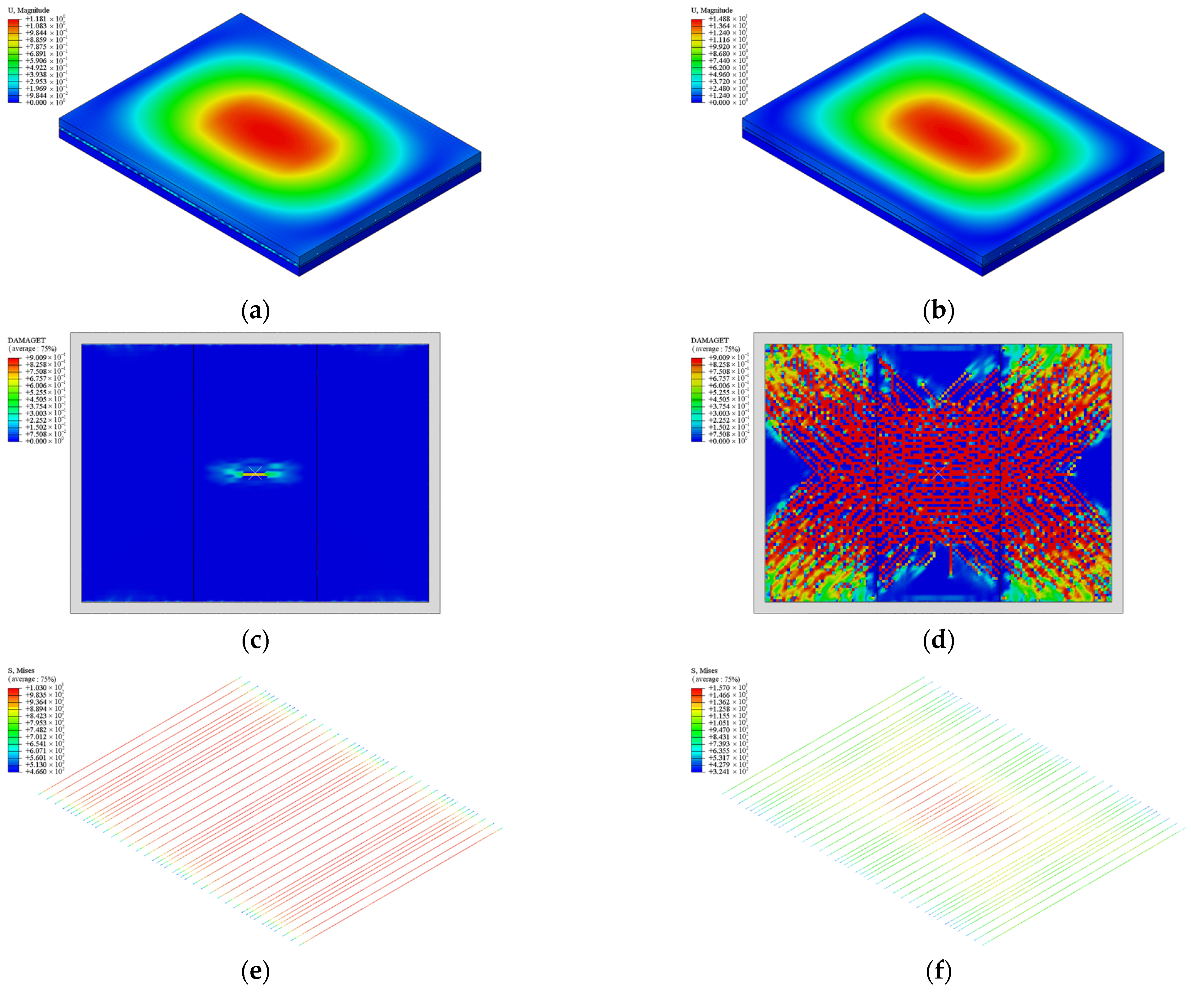
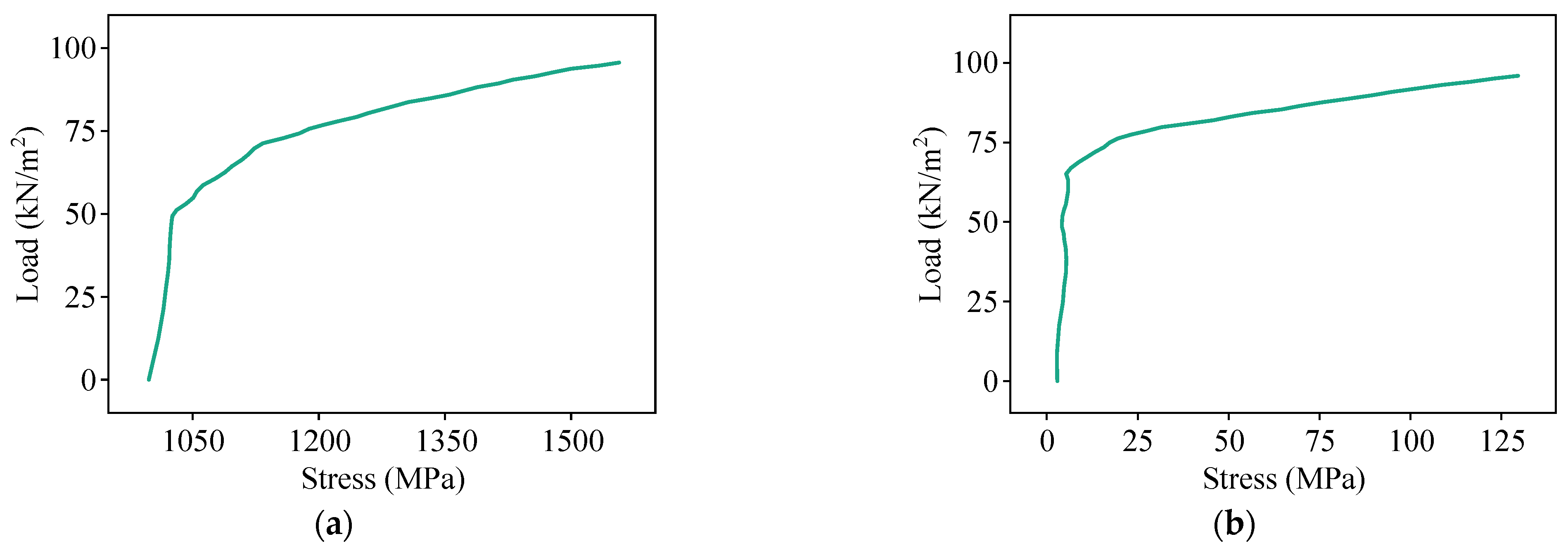
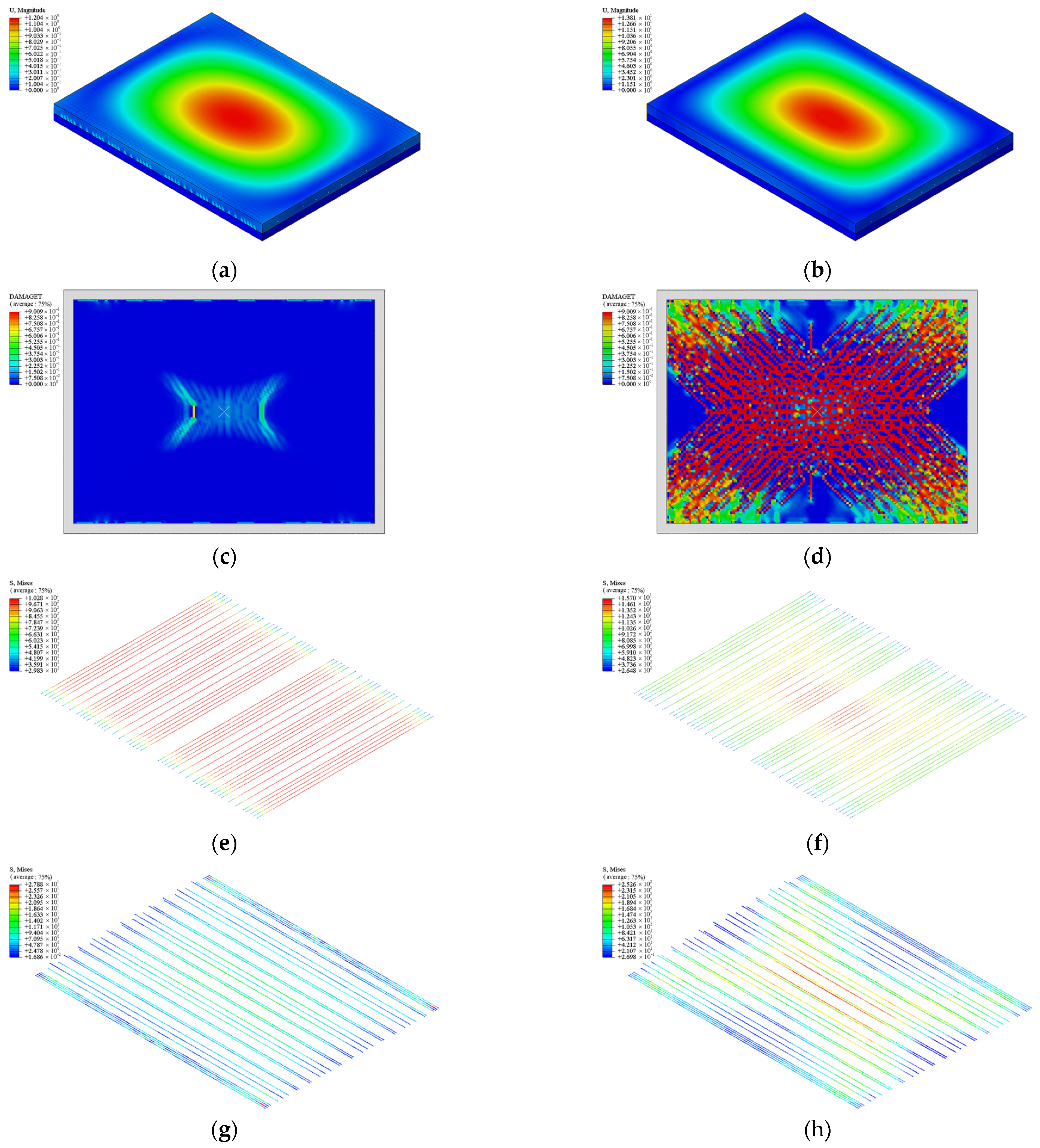
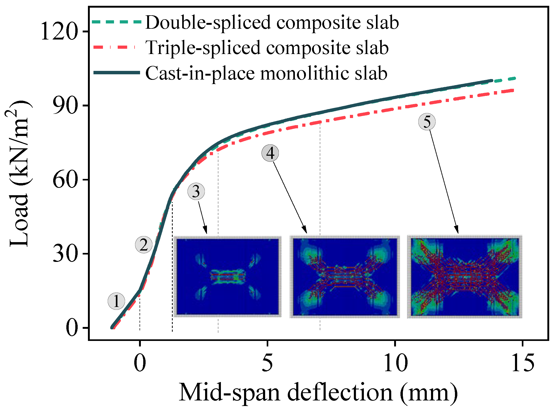
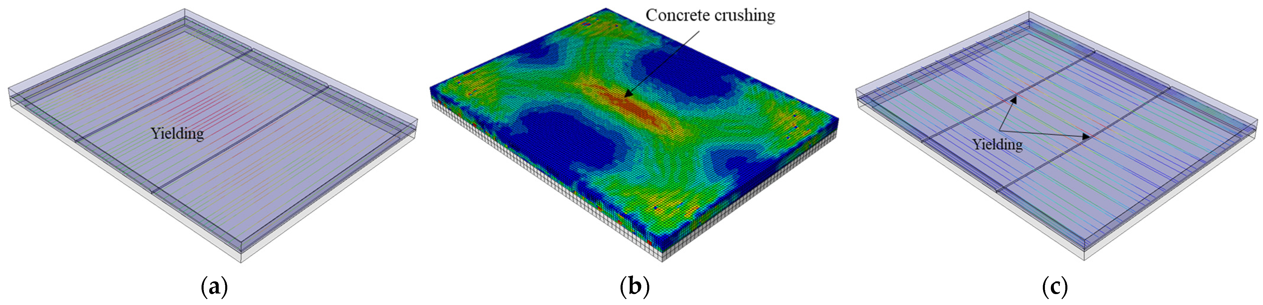
- For bidirectional bending performance, the loading behavior of the composite and monolithic slabs can be categorized into five distinct stages: the decompression state, elastic state, incipient cracking state, diagonal cracking state, and fully cracked state. All the slabs demonstrate comparable stiffness prior to cracking and similar crack distributions at failure, with a checkerboard pattern near the mid-span and extending diagonally toward the slab corners. The presence of splicing joints reduces the post-crack stiffness slightly and increases the ultimate deflections of the double-spliced and triple-spliced composite slabs, which are 7.53% and 7.75% greater than that of the monolithic slab, respectively. Nonetheless, the ultimate capacities remain close to that of the cast-in-place slab.
- (3)
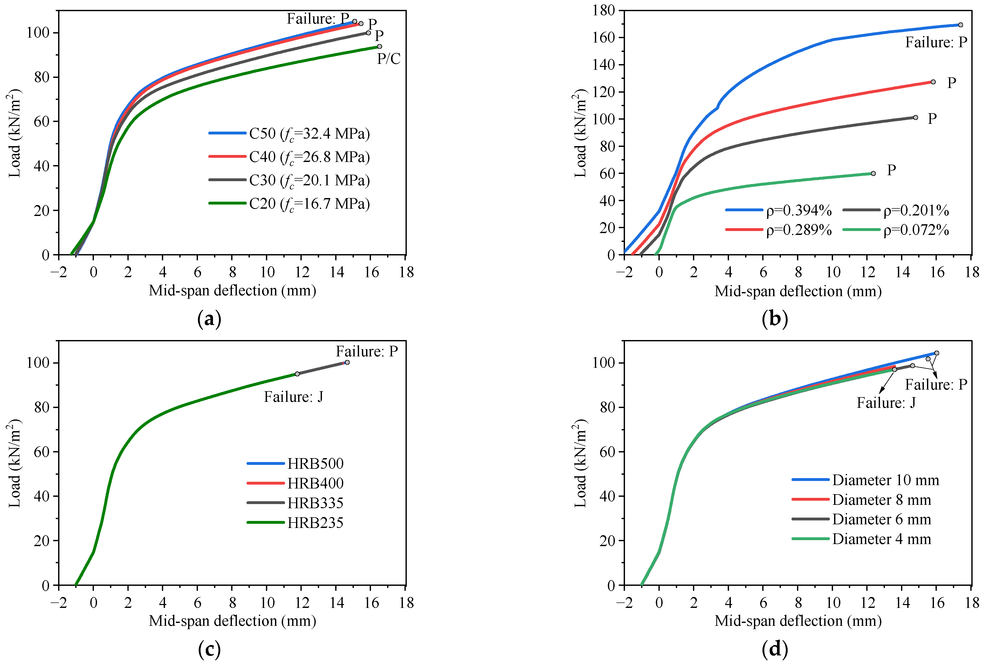
- The parametric analysis shows that the longitudinal prestressing steel ratio has the most significant effect on the behavior of the bidirectional slab, with the ultimate bearing capacity increasing in proportion to the prestressing steel ratio from 0.072% to 0.394%. The beneficial effect of the increase in concrete strength on the bearing capacity gradually decreases, especially after C40. When the arrangement of the joint-connecting rebars greater than C4 @ 200 mm with a minimum yield strength of 235 MPa, the transversal force transfer across the joints is reliable.
- (4)
- The new type of prestressed concrete composite slabs with steel ribs introduced in this study features high cracking strength, stiffness, load-bearing capacity, and commendable ductility under both unidirectional and bidirectional loading conditions, making it highly appropriate for substation applications. For different substation sizes, the ratio of the prestressing steel should be adjusted to meet the capacity requirements. For a larger room space, a grid of secondary beams can be set beneath the floor slabs to form a two-way slab system to obtain a higher bending performance.
Author Contributions
Funding
Data Availability Statement
Conflicts of Interest
References
- Luo, T.; Xue, X.L.; Wang, Y.N.; Xue, W.R.; Tan, Y.T. A systematic overview of prefabricated construction policies in China. J. Clean Prod. 2021, 280, 124371. [Google Scholar] [CrossRef]
- Bonamente, E.; Cotana, F. Carbon and energy footprints of prefabricated industrial buildings: A systematic life cycle assessment analysis. Energies 2015, 8, 12685–12701. [Google Scholar] [CrossRef]
- Bai, S.; Li, M.C.; Song, L.G.; Kong, R. Developing a common library of prefabricated structure components through graphic media mapping to improve design efficiency. J. Constr. Eng. Manag. 2021, 147, 04020156. [Google Scholar] [CrossRef]
- Jiang, Y.; Shu, J.P.; Ye, J.; Zhao, W.J. Virtual trail assembly of prefabricated structures based on point cloud and BIM. Autom. Constr. 2023, 155, 105049. [Google Scholar] [CrossRef]
- He, H.; Zhou, S.; Zhang, L.; Zhao, W.; Xiao, X. Dynamic accounting model and method for carbon emissions on the power grid side. Energies 2023, 16, 5016. [Google Scholar] [CrossRef]
- Li, C.Z.; Chen, Z.; Zhao, Y.Y.; Zhou, M.Z.; Zhang, L.M. Design and Application of Prefabricated Substation Based on BIM Technology. In Proceedings of the 24th International Symposium on Advancement of Construction Management and Real Estate, Chongqing, China, 29 November–2 December 2021. [Google Scholar] [CrossRef]
- Zhao, Y.Y.; Li, R.; Yue, S.Y. Comparative Analysis of Modular Prefabricated Module Substation and Conventional Substation. In Proceedings of the 3rd International Conference on Cognitive based Information Processing and Applications, Guangzhou, China, 2–3 November 2023. [Google Scholar] [CrossRef]
- Shen, Q.S.; Sheng, X.H.; Jiang, X.Y.; Wu, L.; Sheng, S.Y. Design research and engineering application of substation assembled fence and firewall. Zhejiang Electr. Power 2014, 33, 28–33. [Google Scholar] [CrossRef]
- Li, T.; Guo, J.; Hu, S.Y.; Chai, L.J.; Jing, Z.P.; Cheng, R.; Wang, Z.L. Research on the design of the integrated wall panel of the prefabricated building in substations. J. Phys. Conf. Ser. 2021, 1904, 012026. [Google Scholar] [CrossRef]
- Hou, G.R.; Wang, X.X.; Lu, N.N.; Xie, J.G.; Huang, G. Experimental study on seismic behavior of new prefabricated partial SRC frame beam-column joints. Build. Struct. 2018, 48, 27–32. [Google Scholar] [CrossRef]
- Liu, Y.; Wei, Z.Z.; Zhen, Y.C.; Jiao, J.F. Application exploration and practice of prestressed steel pipe truss floor slab in substation. Shandong Electr. Power 2021, 48, 39–43. [Google Scholar]
- Yu, J.H.; He, M.J.; Zhang, S.H.; Zhao, Y.Y.; Tang, Y.X. Experimental study on the mechanical behavior of prestressed concrete steel pipe truss composite slabs under the influence of secondary force. Build. Struct. 2021, 51, 80–85. [Google Scholar] [CrossRef]
- Huang, H.L.; Wu, F.B.; Zhu, M.Q.; Zeng, C.; Lv, W. Influence of rib details on flexural behavior of concrete composite slab with precast prestressed ribbed pane. J. Build. Struct. 2015, 36, 66–72. [Google Scholar] [CrossRef]
- Liu, J.P.; Hu, H.F.; Li, J.; Chen, Y.F.; Zhang, L. Flexural behavior of prestressed concrete composite slab with precast inverted T-shaped ribbed panels. Eng. Struct. 2020, 215, 110687. [Google Scholar] [CrossRef]
- Hou, H.T.; Liu, X.; Qu, B.; Ma, T.; Liu, H.; Feng, M.; Zhang, B. Experimental evaluation of flexural behavior of composite beams with cast-in-place concrete slabs on precast prestressed concrete decks. Eng. Struct. 2016, 126, 405–416. [Google Scholar] [CrossRef]
- Karimipanah, A.; Zeynalian, M.; Ataei, A. Structural performance of cold formed steel composite beams with profiled steel sheeting. Int. J. Civ. Eng. 2024, 22, 1099–1116. [Google Scholar] [CrossRef]
- Lei, X.S.; Ouyang, J.W.; Wang, Y.F.; Wang, X.H.; Zhang, X.F.; Chen, F.; Xia, C.; Liu, Z.; Zhou, C.Y. Thermal–Mechanical Coupling Evaluation of the Panel Performance of a Prefabricated Cabin-Type Substation Based on Machine Learning. Fire 2021, 4, 93. [Google Scholar] [CrossRef]
- Wang, G.S.; Liu, J.H.; Zhang, Y.B.; Zhang, Z.Y.; Tao, J.W.; Wu, D.Y. Theoretical and experimental study on the stress state of joints in two-way composite slabs. Buildings 2024, 14, 3374. [Google Scholar] [CrossRef]
- Li, J.; Ni, D.Y.; Liu, X.; Zhang, J.R. Experimental study of mechanical properties of L-shaped joint laminated two-way slabs. Build. Struct. 2020, 50, 67–71. [Google Scholar] [CrossRef]
- Cheng, Z.J.; Ma, Z.Z.; Hu, J.; Yu, S.L.; Zhao, Y. Experimental research on heap loading of reinforced concrete composite two-way slab with lattice girders and connected without gap. Build. Struct. 2021, 51, 111–119. [Google Scholar] [CrossRef]
- Chen, Y.H.; Lu, D.; Zhang, M.; Sun, H.W.; Xie, G.X. Research on connection technique for bidirectional composite floor slabs without gap. Ind. Constr. 2020, 50, 31–35. [Google Scholar] [CrossRef]
- T/CECS 1289-2023; Technical Specification for Prestressed Concrete Composite Slab with Steel Ribs. China Association for Engineering Construction Standardization: Beijing, China, 2023.
- Abaqus. Computer Software, Version 6.14; SIMULIA: Providence, RI, USA, 2014.
- Hou, H.T.; Feng, M.Y.; Qiu, C.X.; Lan, R.H.; Qu, B.; Wang, Y.M.; Tian, L. Experimental study and numerical simulation on prestressed concrete composite slab with steel ribs. Build. Struct. 2018, 39, 103–110. [Google Scholar]
- GB 50010-2010; Concrete Structure Design of Concrete Structures. Ministry of Housing and Urban-Rural Development of the People’s Republic of China: Beijing, China, 2012.
- Chen, X.; Li, H.S.; Gao, M.Q.; Sun, J.G.; Hou, H.T. Experimental study and numerical simulation on prestressed concrete composite slab with steel ribs. Build. Struct. 2021, 51, 98–103+60. [Google Scholar]


| Component | Young’s Modulus (MPa) | Poisson’s Ratio | Yield Stress (MPa) |
|---|---|---|---|
| Prestressing steel | 206,000 | 0.3 | 1570 |
| Rebar | 206,000 | 0.3 | 400 |
| Steel rib | 206,000 | 0.3 | 235 |
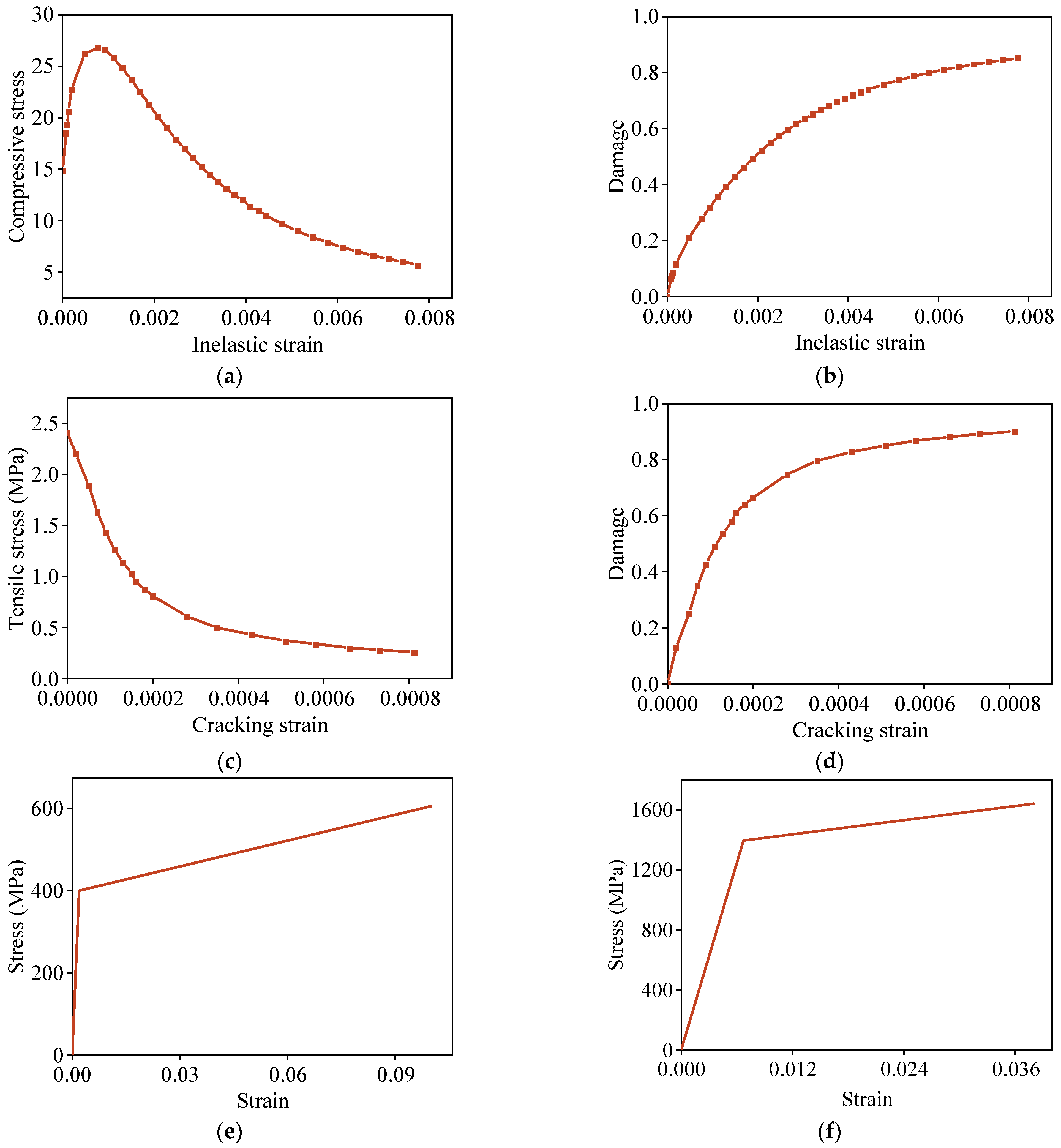
| Concrete | 32,500 | 0.2 | 2.4/26.8 1 |
| Dilation Angle | Eccentricity | fb0/fc0 | K | Viscosity Parameter |
|---|---|---|---|---|
| 30 | 0.1 | 1.16 | 0.6667 | 0.005 |
Disclaimer/Publisher’s Note: The statements, opinions and data contained in all publications are solely those of the individual author(s) and contributor(s) and not of MDPI and/or the editor(s). MDPI and/or the editor(s) disclaim responsibility for any injury to people or property resulting from any ideas, methods, instructions or products referred to in the content. |
© 2025 by the authors. Licensee MDPI, Basel, Switzerland. This article is an open access article distributed under the terms and conditions of the Creative Commons Attribution (CC BY) license (https://creativecommons.org/licenses/by/4.0/).
Share and Cite
Li, L.; Liu, Y.; Wei, Z.; Jiang, Y.; Chen, H.; Zhang, Y.; Liu, C.; Rong, K.; Tian, L. Numerical Study on the Bending Performance of Steel-Ribbed Composite Slabs for Substations. Appl. Sci. 2025, 15, 2876. https://doi.org/10.3390/app15062876
Li L, Liu Y, Wei Z, Jiang Y, Chen H, Zhang Y, Liu C, Rong K, Tian L. Numerical Study on the Bending Performance of Steel-Ribbed Composite Slabs for Substations. Applied Sciences. 2025; 15(6):2876. https://doi.org/10.3390/app15062876
Chicago/Turabian StyleLi, Lin, Yong Liu, Zhenzhong Wei, Yunan Jiang, Haomiao Chen, Yu Zhang, Chen Liu, Kunjie Rong, and Li Tian. 2025. "Numerical Study on the Bending Performance of Steel-Ribbed Composite Slabs for Substations" Applied Sciences 15, no. 6: 2876. https://doi.org/10.3390/app15062876
APA StyleLi, L., Liu, Y., Wei, Z., Jiang, Y., Chen, H., Zhang, Y., Liu, C., Rong, K., & Tian, L. (2025). Numerical Study on the Bending Performance of Steel-Ribbed Composite Slabs for Substations. Applied Sciences, 15(6), 2876. https://doi.org/10.3390/app15062876