Article

Suppression Mechanisms of Stratified Jet-in-Crossflow on Thermoacoustic Instability and NOx Emissions in Premixed Combustors

School of Energy and Power Engineering, Nanjing Institute of Technology, Nanjing 211167, China
*
Author to whom correspondence should be addressed.
Appl. Sci. 2025, 15(5), 2819; https://doi.org/10.3390/app15052819
Submission received: 6 February 2025 / Revised: 28 February 2025 / Accepted: 4 March 2025 / Published: 5 March 2025
(This article belongs to the Section Aerospace Science and Engineering)

Abstract

:
The premixed combustion of a gas turbine is prone to thermoacoustic oscillation, which affects the safety of combustion systems. This study experimentally investigated the suppression mechanism of a stratified jet-in-crossflow on the thermoacoustic instability and nitrogen oxides (NOx) in an unstable lean-premixed combustor. Two key parameters of the jet-in-crossflow—gas density and jet flow rate—were investigated to elucidate their effect on momentum ratios. The results reveal that the stratified jet-in-crossflow reduces the maximum amplitude of combustion oscillation by 58%, while the NOx concentration exhibits a high damping ratio of 48.8%. Higher jet flow rates and gas densities enhance the suppression of combustion thermoacoustic oscillations and NOx emissions. The distribution of flame radicals indicates that an increase in the jet flow rate reduces the intensity of the flame heat release rate, thereby reducing the flame thermoacoustic instability. As the argon/helium volume ratio increases, the mode of thermoacoustic oscillation shifts. As the argon/helium volume ratio gradually increases from 0%/100% to 100%/0%, the main frequency of thermoacoustic oscillations gradually decreases from 267 to 121 Hz. Notably, the transient amino-group radicals in the flame increase with the increasing argon/helium volume ratio, indicating that the jet suppresses NOx generation. The changes in peak temperature and flame shape after jetting further confirm that the stratified jet-in-crossflow alters the flame structure within the combustion chamber. The effect of the momentum ratio on the suppression of thermoacoustic instability is studied for the first time. This study provides a promising method for suppressing the thermoacoustic oscillations and NOx emissions in premixed flames, contributing to a safer operation and cleaner emissions in lean-premixed combustors.

1. Introduction

Premixed combustion thermoacoustic oscillations commonly occur in gas turbines, aircraft engines, and gas boilers. These oscillations disrupt the stable operation of the combustion system and cause burner resonance, which may lead to structural damage [1]. Additionally, the thermoacoustic oscillations can cause deviations in the burner operations and lead to fluctuations in the flame equivalence ratio and changes in the flame structure, which significantly increase NOx emissions [2]. In recent years, with the widespread adoption of carbon neutrality, traditional power equipment, such as gas turbines, has shifted from being fueled by natural gas to co-firing with hydrogen fuel. This shift has exacerbated issues such as thermoacoustic oscillations and NOx emissions. However, the accurate prediction of thermoacoustic oscillations remains challenging [3]. Therefore, it is crucial to effectively suppress combustion thermoacoustic oscillations and reduce NOx emissions. Combustion thermoacoustic oscillations exhibit complex multi-field coupling characteristics and can induce unstable phenomena, such as flashback and blowout, making their efficient control a major challenge [4].
Generally, control methods for thermoacoustic oscillations can be classified into active and passive control [5]. Active control methods utilize advanced measurements and execution mechanisms combined with advanced control techniques to achieve closed-loop control of combustion thermoacoustic oscillations [6]. However, these methods are still limited by the frequency and reliability of actuators and have not been widely adopted in actual gas turbine combustion systems [7]. Passive control methods typically utilize mufflers and other techniques to eliminate combustion chamber sound waves or disrupt the thermoacoustic coupling process, which alters the flame heat release rate through pilot fuel injection [8,9]. Compared with active control methods, passive control methods provide higher reliability and a simpler design, but their suppression frequency band is narrower [10]. In complex and variable thermoacoustic oscillation modes, such as high-order, multi-mode, and time-varying thermoacoustic oscillations, the suppression effect of passive methods is less effective. With the decarbonization of existing gas turbine fuels, such as hydrogen (H2) and ammonia (NH3)-blended natural gas, the application of these fuels will result in more complex thermoacoustic oscillation behaviors [11,12]. These challenges hinder the effective suppression of thermoacoustic oscillations. Therefore, developing control methods capable of managing complex and variable thermoacoustic oscillations is crucial. Compared with traditional active or passive control methods, the use of jet-in-crossflow can effectively suppress combustion thermoacoustic oscillations and adjust the flame structure and chemical reaction processes [13,14]. By changing the coupling between flame heat release rate and sound wave, jet-in-crossflow can suppress the problem of combustion instability. However, the jet-in-crossflow method is complex and involves a flow-flame-acoustic coupling process. Although numerous researchers have confirmed the control effect of microjets on combustion instabilities, the suppression process is influenced by several parameters, and the underlying suppression mechanism remains unclear.
Researchers have explored the influence of various jet media and parameters on thermoacoustic oscillations, including hydrogen, air, inert gases, and oxygen-rich gases. Zhou and Tao [15] investigated the effects of annular N2/O2 and CO2/O2 jets on combustion instabilities and NOx emissions in lean-premixed methane flames, achieving a synchronous suppression effect. Hu and Zhou [16] controlled the combustion instability and NOx emissions using an adjustable swirl jet in lean-premixed flames. Liu et al. [17] examined the combustion instability profile of ethanol and n-heptane fuels under different combustor geometries and suppressed the combustion instability using CO2–O2 or CO2–Ar jet-in-crossflows. Oztarlik et al. [18] investigated the suppression effects of hydrogen microjets on the combustion instability, highlighting the need to consider changes in flame NOx emissions after jetting. Barbosa et al. [19] examined the suppression of combustion oscillations using local hydrogen jets and highlighted the high-temperature challenges caused by hydrogen doping. Balasubramanian et al. [20,21] investigated the mitigation of combustion instabilities through local diluent injections in a premixed swirl-stabilized combustor. The results confirmed that carbon dioxide and nitrogen effectively controlled combustion instabilities. Cao et al. [22] explored the flow structures in a lean-premixed swirl-stabilized combustor with a microjet air injection. The results indicated that vortex shedding in the recirculation zone inside and outside the flame plays a key role in suppressing thermoacoustic oscillations. Fang et al. [23] found that the pressure oscillations could be effectively suppressed by flue gas jets and maintain relatively low levels of CO and NOx emissions. Li et al. [24] revealed that fuel injection parameters can influence the stability and emission performance of the combustion system. Tao and Zhou [25,26] confirmed that superheated steam and CO2/O2 jet-in-crossflows could suppress the thermoacoustic instability. Omi et al. [27] investigated the effect of low-bandwidth open-loop control on the combustion instability using high-momentum air jets. The results revealed that jets can significantly alter the distribution area of flame heat-release pulsations. These studies suggest that air injection methods, such as jet-in-crossflow, can suppress the thermoacoustic oscillations and regulate NOx emissions. Owing to its low cost, ease of implementation, and high reliability, jet-in-crossflow has emerged as a vital method for investigating thermoacoustic instability and NOx emission characteristics at different momentum ratios [28]. Unlike hydrogen, inert jets, such as argon or helium, can adjust the flame equivalence ratio without causing overheating issues. The aforementioned studies indicate that the components of the jet medium significantly affect the thermoacoustic oscillation suppression, while the jet mode determines the final control effectiveness. Additionally, recent studies have shown that stratified combustion modes can enhance flame stability and reduce NOx emissions [29]. Although stratified combustion and jet-in-crossflow methods regulate combustion and emission performance, no research has yet explored the effect of stratified jet-in-crossflow on combustion instability.
Although scholars have investigated the inhibitory effects of microjet injections on thermoacoustic instability and NOx emissions, no studies have explored the control of combustion oscillations using stratified jet-in-crossflow. Currently, no research has examined the use of stratified jet-in-crossflow with different parameters to control the thermoacoustic oscillations. To address this gap, this paper aims to explore the characteristics of thermoacoustic oscillations and NOx emissions at different argon/helium volume ratios and flow rates. Notably, jet parameters can influence the behavior of thermoacoustic oscillation modes. Therefore, this study investigates the effect of stratified Ar/He jet-in-crossflow on the migration of these oscillation modes. Overall, this paper aims to elucidate the suppression mechanisms of stratified jet-in-crossflow. This study investigated the control effects of different jet flow rates and Ar/He volume ratios. This research combines the advantages of jet-in-crossflow and stratified combustion modes to provide a method for suppressing the thermoacoustic oscillations and NOx emissions. These findings provide valuable guidance for controlling the unstable combustion of fuels, such as hydrogen-blended methane.

2. Experimental Setup

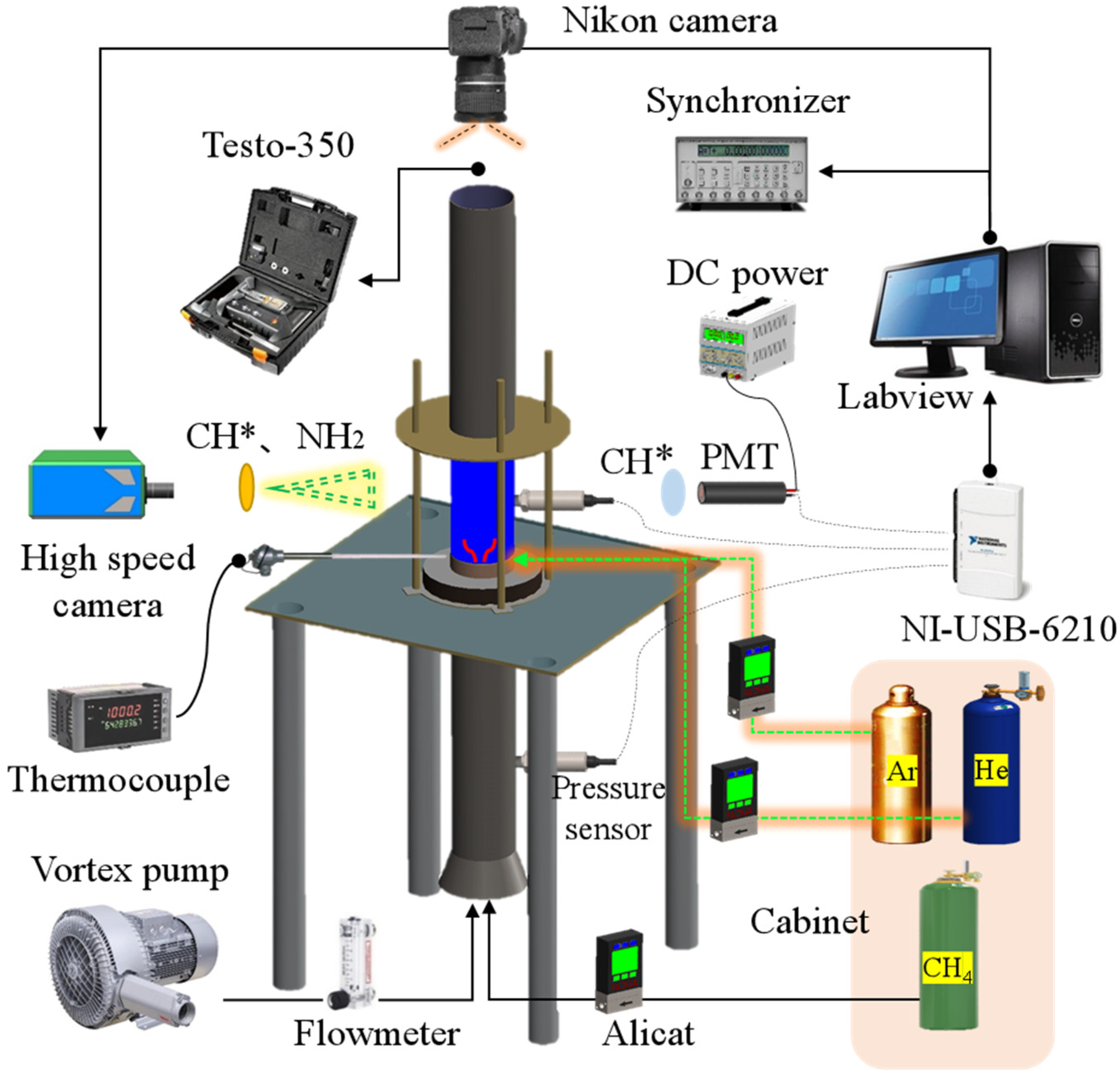
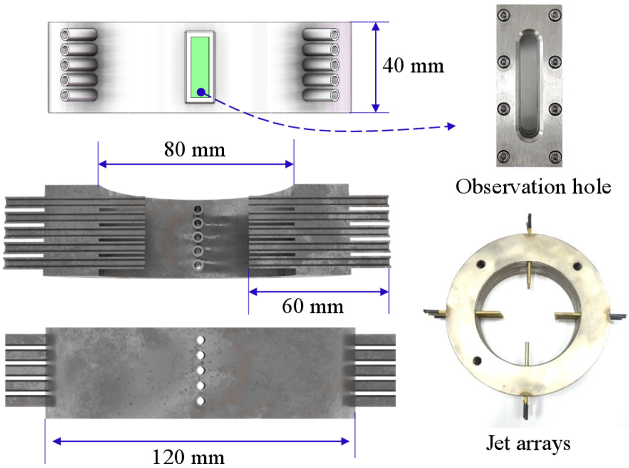
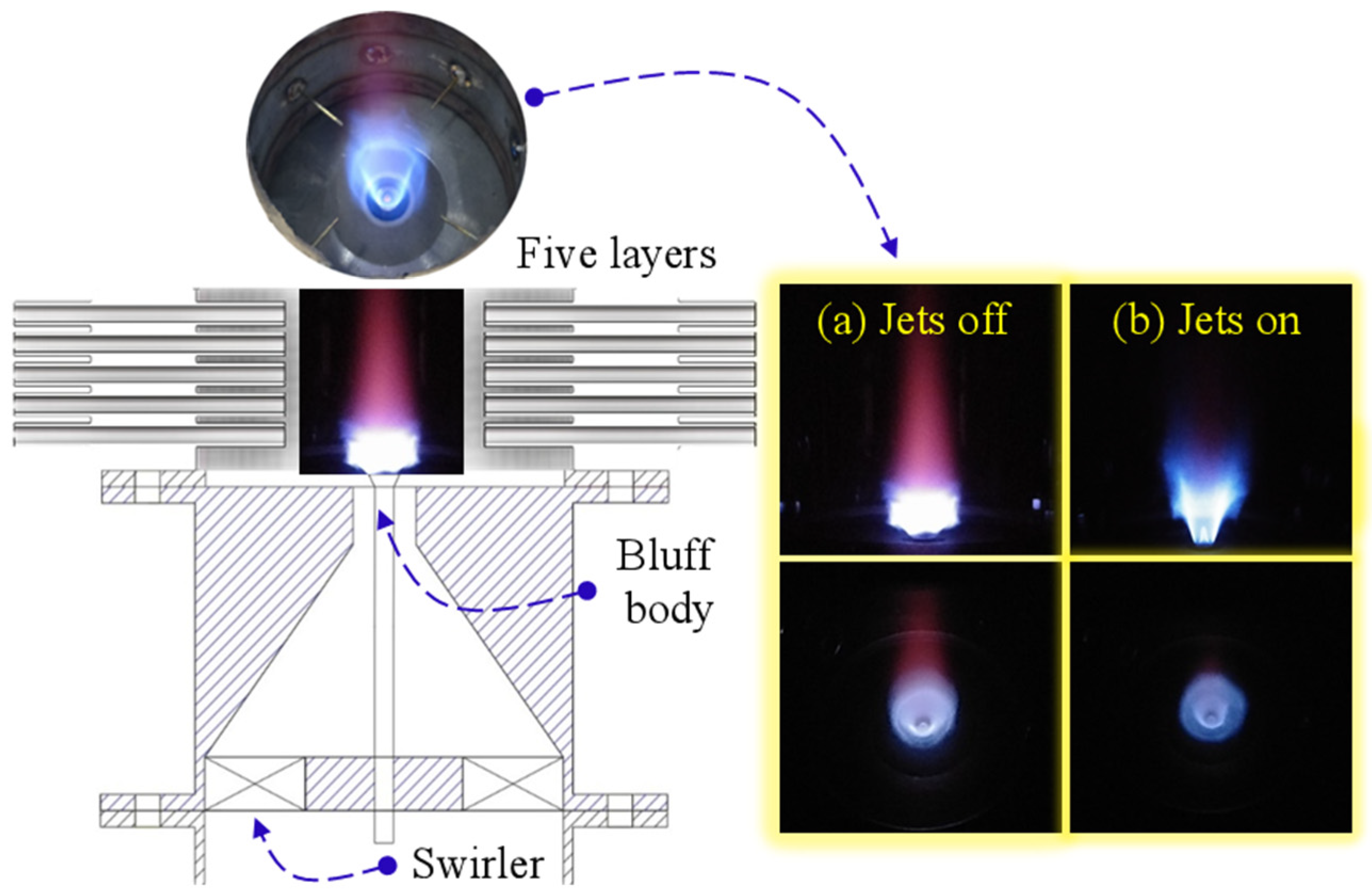
2.1. Combustion Test Bench and Instruments

The experiment was performed using a lean-premixed burner with thermoacoustic oscillations. During the experiment, the thermal power of the burner was maintained at 4 kW, and the flame equivalence ratio was set at 0.75. The burner is classified into upper and lower sections (Figure 1). The lower section serves as the inlet and mixing area for the premixed gas, while the upper section functions as the combustion chamber and exhaust outlet. The burner has a total height of 1500 mm, with the flame positioned 750 mm from the bottom. Combustion air is supplied by an air pump, and the airflow is regulated using the glass rotameter. Methane, carbon dioxide, and oxygen are supplied through high-pressure cylinders, and their flows are regulated using an Alicat MC series flowmeter (Alicat Scientific, Inc., Tucson, AZ, USA). The sound pressure fluctuation signal during the thermoacoustic oscillations is captured by a high-frequency dynamic pressure sensor (Kunshan Shuangqiao Sensor, Kunshan, China). The flame heat release pulsation signal is recorded using a photomultiplier tube (PMT, Hamamatsu, Japan), with a flame radical filter (CH*, 430 ± 10 nm) positioned in front of the PMT. Both the pressure sensor and PMT are powered by a programmable DC power supply. The collected sound pressure and flame heat release signals are captured using a high-frequency dynamic data acquisition card (NI-USB-6210) with a sampling frequency of 10 kHz. The thermoacoustic oscillation signals are stored on a computer using the LabVIEW 2012 software. Flame images are captured with a high-speed camera, synchronized with the thermoacoustic oscillation signal through a signal synchronizer (DG 645). Flame filters for CH* (430 ± 10 nm) and NH2* (630 ± 10 nm) are positioned in front of the high-speed camera to capture the distribution characteristics of free radicals in the unstable flame. The Abel inverse transform method was used for flame CH* and NH2* image processing. In this study, the measurement uncertainties of flame free radicals by a high-speed camera was less than 2.23%. The original flame image was captured using a Nikon camera to observe changes in the flame morphology before and after the introduction of argon/helium jets. During the experiment, the temperature field of the flame was measured and reconstructed using high-precision thermocouples. The flue gas generated from the combustion is analyzed using a flue gas analyzer (Testo-350, Black Forest, Germany), and the measured values are corrected to 15% oxygen content. The temperature field data were collected five times, with an error margin below 3%. To analyze the mode transition characteristics of thermoacoustic instability, nonlinear analysis tools, such as phase space distribution diagrams, were used to elucidate the evolution of thermoacoustic instability [30].

2.2. Method and Materials

Thermoacoustic oscillations and NOx emissions are controlled using the Ar/He stratified jet-in-crossflow in this study (Figure 2). The stratified jet-in-crossflow structure consists of five layers, each with a height of 40 mm. A fire observation hole is installed on the wall of the layered structure for flame photography. The layered structure exhibits an inner diameter of 80 mm and an outer diameter of 120 mm. Each layer is equipped with four transverse jet holes, with adjustable diameters (Figure 2). In this study, the diameters of the inert gas jet holes are set to 2.0, 2.5, 3.0, and 3.5 mm to investigate the effect of injection velocity. The burner features a swirl premixed structure and a bluff body combustion stabilization design (Figure 3). The five-layer jets are positioned to directly interact with the premixed flame at the burner outlet. Figure 3a,b show the schematic of flame shape changes before and after the jets are introduced. The premixed methane and air mixture infiltrates the combustion chamber through the bluff body after flowing through the swirler, which has a swirl angle of 60°. The bluff body outlet has an outer diameter of 12 mm and an inner diameter of 22 mm. During the combustion experiments, the thermal power and equivalence ratio of the burner remain constant. The variations in thermoacoustic oscillations and NOx emissions within the combustion chamber were investigated at different flow rates and argon/helium volume ratios. The jet-in-crossflow consists of argon and helium, with jet flow rates set at 1.0, 2.0, 3.0, 4.0, 5.0, 6.0, and 7.0 L/min. The Ar/He volume ratios are set to 0%/100%, 25%/75%, 50%/50%, 75%/25%, and 100%/0%. The mixed gas density of argon and helium is designed to examine the effect of jet-in-crossflow. The mixed gases exhibit densities of 1.784, 1.383, 0.982, 0.581, and 0.18 kg/m3. The maximum density of the mixed inert gases is nearly 10 times that of the minimum density. Before the introduction of jet-in-crossflow, the sound pressure amplitude in the combustion chamber is 25.18 Pa. The experimental conditions are summarized in Table 1. In this study, when the burner enters the thermoacoustic oscillation state, firstly, the signal synchronizer is combined to synchronously measure the combustion chamber acoustics, flame heat release rate, and flame images, and then the jet device is turned on to record the flame thermoacoustic oscillation signal and flame shape changes before and after the jet. At the same time, measure the NOx emission concentration of the flue gas at the burner outlet before and after the jet. In each measurement, the condition is tested at least five times, and the MSE (mean square error) of all measurement points was below 2.05%, which is less than 5%.

3. Results and Discussions

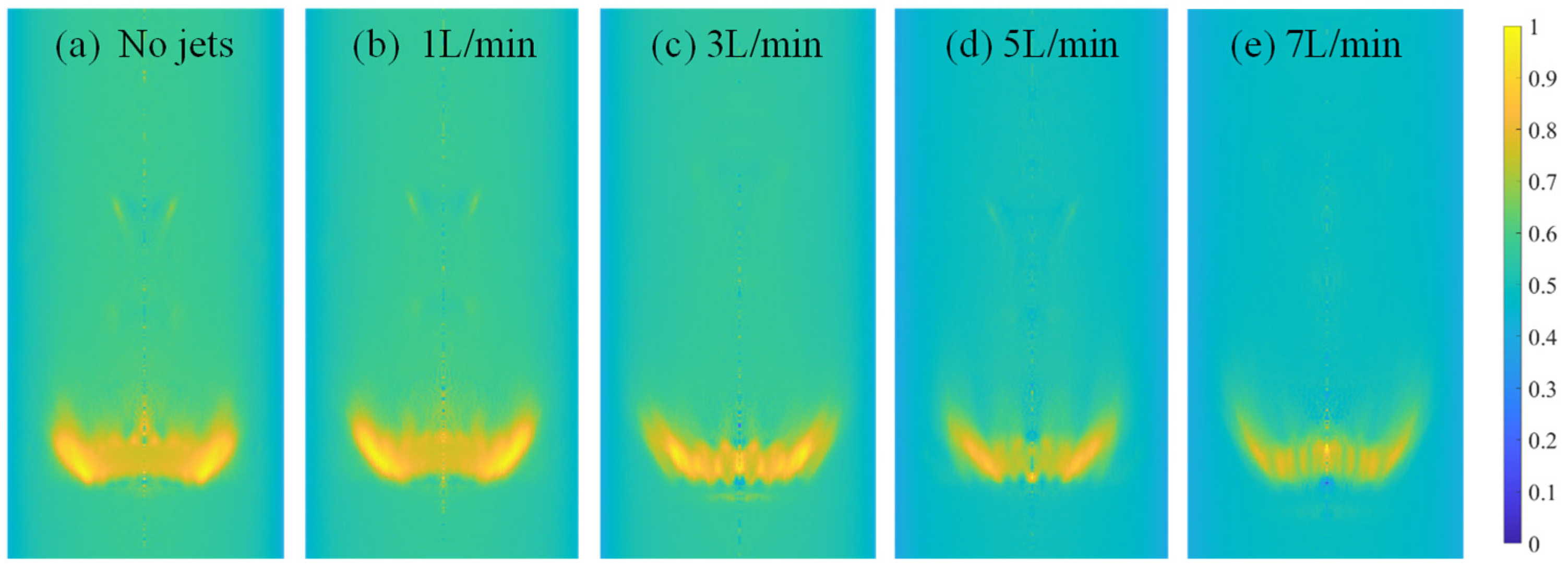
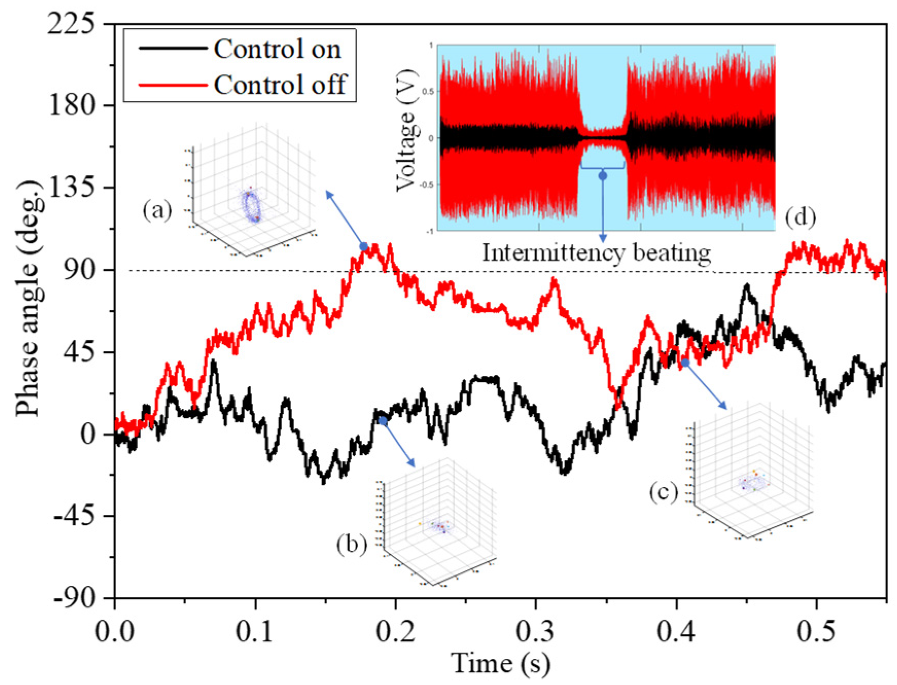
3.1. Suppression of Thermoacoustic Instability

This study investigated the evolution characteristics of thermoacoustic instability (Figure 4) and compared the intensity of thermoacoustic oscillations at different jet flow rates and gas densities. Figure 4a–d represent jet hole diameters ranging from 2.00 to 3.50 mm. With the increasing jet flow, the sound pressure intensity in the combustion chamber decreases, which is 25.18 Pa lower than the original oscillation amplitude (Figure 4). However, the amplitude of sound pressure does not decrease linearly. At a jet flow below or equal to 4 L/min, the sound pressure amplitude increases with the increasing jet flow, reaching a maximum amplitude of 24.8 Pa. As the jet flow rate exceeds 4 L/min, the sound pressure amplitude decreases, reaching a minimum sound pressure of 10.6 Pa. This indicates a significant inhibitory effect once the jet flow rate exceeds the critical value of 4.0 L/min. However, excessive jet-in-crossflow can cause a flame blowout. The diameter of the jet-in-crossflow influences the intensity of combustion oscillations. The effects of 3.00 and 3.50 mm apertures are more pronounced than those of 2.50 and 2.00 mm apertures. Therefore, this study examined the evolution characteristics of thermoacoustic oscillations at a jet aperture of 3.5 mm. The Ar/He volume ratio significantly affects the combustion oscillation amplitude, which decreases as the Ar/He volume ratio diminishes.
To further examine the variation characteristics in the flame heat release rate, the Abel inverse transform of the CH* distribution under the stratified Ar/He jet-in-crossflow was analyzed (Figure 5). The jet flow rates are set at 1.0, 3.0, 5.0, and 7.0 L/min, with an Ar/He volume ratio of 0%/100%. The aperture of the stratified Ar/He jet-in-crossflow is set to 3.50 mm. With the increasing jet-in-crossflow rate, the intensity of the flame CH* heat release rate gradually decreases. This indicates that the stratified Ar/He jet-in-crossflow effectively mitigates flame heat release pulsation aggregation and alters the distribution of flame heat release rate pulsation. Before the jet flow is introduced, the flame heat release is concentrated near the burner nozzle. However, as the jet flow rate increases to 7 L/min, the concentrated area of the flame heat release rate becomes more diffuse. According to the variation patterns of sound pressure amplitude (Figure 4), the stratified Ar/He jet-in-crossflow can effectively disrupt the coupling between the flame, sound, and flow, thereby altering the energy transfer pathway between the flame front and sound waves. The stratified Ar/He jet-in-crossflow suppresses the persistence of thermoacoustic oscillations in the combustion chamber.

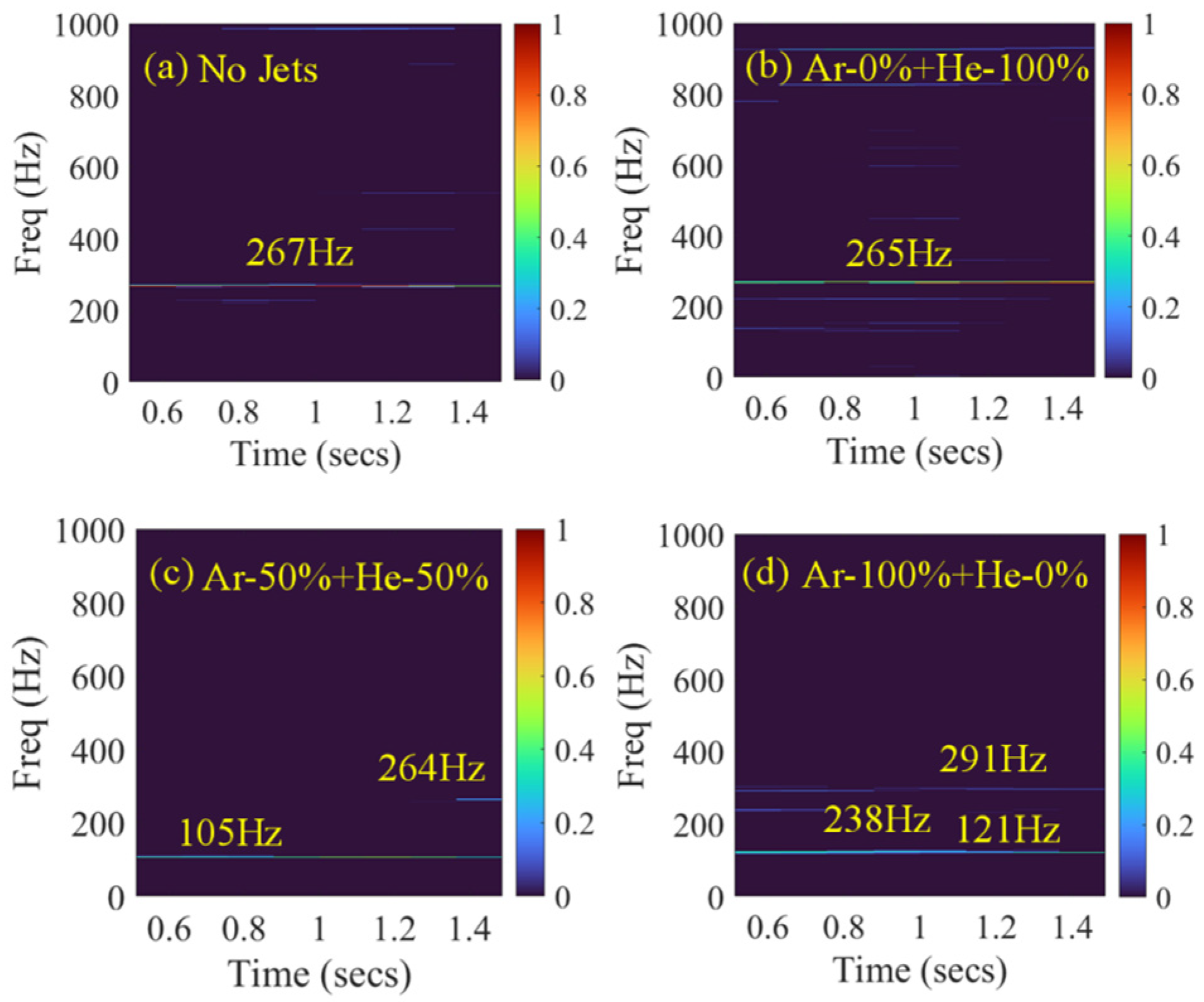
3.2. Transition of Thermoacoustic Instability Modes

To analyze the migration characteristics of thermoacoustic oscillation modes under the stratified Ar/He jet-in-crossflow, the fast Fourier transform (FFT) analysis was performed on sound pressure oscillations under typical operating conditions (Figure 6). This study examined the thermoacoustic oscillation response at a jet aperture of 3.50 mm and a jet flow rate of 5 L/min. The Ar/He volume ratios were set to 0%/100%, 50%/50%, and 100%/0%. In the absence of stratified jet-in-crossflow, the oscillation amplitude is 25.18 Pa, with an oscillation frequency of 267 Hz (Figure 6). At an Ar/He volume ratio of 0%/100%, the oscillation amplitude decreases to 17.35 Pa. At an Ar/He volume ratio of 50%/50%, the oscillation amplitude further decreases to 14.38 Pa. Finally, at an Ar/He volume ratio of 100%/0%, the oscillation amplitude decreases to 13.14 Pa. To further explore the mode transfer characteristics of combustion thermoacoustic oscillations, a power spectral density (PSD) analysis of the oscillation signals was performed before and after the jet flow was introduced (Figure 7). The results were obtained through a short-time Fourier analysis (STFT). As the Ar/He volume ratio increases, the thermoacoustic oscillation mode undergoes significant changes (Figure 7). Although the oscillation amplitude is suppressed, the Ar/He jet-in-crossflow induces a shift in the oscillation mode (Figure 6). After the introduction of the Ar/He stratified jet, the main frequency of the thermoacoustic oscillation shifts from 267 to 265 Hz (Figure 7b). As the Ar/He volume ratio increases, the combustion chamber exhibits a multi-modal coexistence state, with an oscillation frequency at 105 Hz (Figure 7c). At an Ar/He volume ratio of 50%/50%, a second-order oscillation is observed at 264 Hz. As the Ar/He volume ratio increases to 100%/0%, more oscillation modes coexist. A PSD analysis reveals three simultaneous oscillation modes: 121, 238, and 291 Hz. These results indicate that the Ar/He jet-in-crossflow can effectively suppress thermoacoustic oscillations, induce the migration and transformation of the original thermoacoustic oscillation modes, and disrupt the coupling between flame and sound waves. A higher density of the jet gas enhances its penetration force, which reduces the intensity of flame heat-release pulsations. The changes in the flow field induced by the jet play a key role in mitigating thermoacoustic instabilities.
To investigate the mode transfer mechanism of thermoacoustic oscillations, the phase difference and nonlinear dynamic characteristics of thermoacoustic oscillations were analyzed before and after the jet was introduced (Figure 8). A thermoacoustic oscillation signal with a duration of 0.55 s was selected, and this signal exhibited intermittent characteristics. Before the jet introduction, the absolute phase difference of the flame thermoacoustic oscillation exceeds 90°. After the jet introduction under certain working conditions, the absolute phase difference decreases below 90°. Before jet control, the thermoacoustic oscillation exhibits a complete limit cycle oscillation state, with the phase difference exceeding 90° (Figure 8a). After jet control, the thermoacoustic oscillation transitions to a semi-stable intermittent state, with a phase difference below 90° (Figure 8c). This semi-stable state is highly prone to evolving into a complete limit cycle oscillation state.
However, after the introduction of the Ar/He stratified jet, the thermoacoustic oscillation shifts to a chaotic state (Figure 8b). According to the Rayleigh criterion, the Ar/He stratified jet effectively suppresses the limit cycle thermoacoustic oscillation and disrupts the original flame-acoustic coupling process (Figure 8). The response characteristics of sound pressure during the opening and closing process of the jet were analyzed (Figure 8). The red line in Figure 8d represents the time series of sound pressure signals in the combustion chamber, while the black line indicates the time series in the premixed chamber. After the introduction of jet-in-crossflow, the sound pressure intensity in the combustion and premixed chambers significantly decreases. This reduction in sound pressure intensity within the methane and air-premixed chamber can minimize fluctuations in the flame equivalence ratio, thereby weakening the intensity of thermoacoustic oscillations. Nonlinear characteristics are crucial for predicting thermoacoustic oscillations. 56–60. The behavior of these thermoacoustic oscillations under Ar/He stratified jets provides valuable guidance for designing burners.

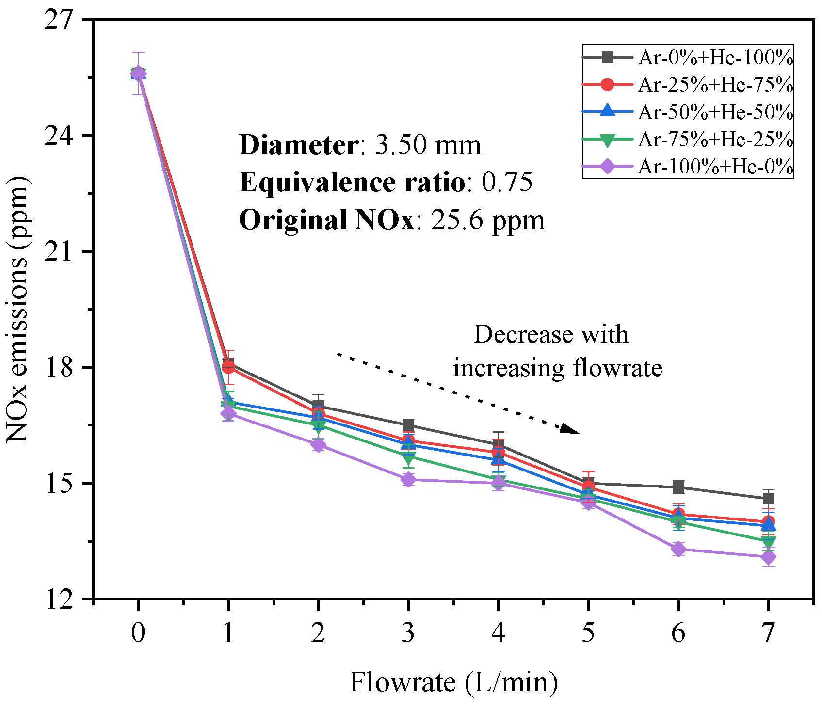
3.3. Suppression of NOx Emissions

This study examined the NOx emission characteristics under different jet-in-crossflow conditions. Before the introduction of the stratified Ar/He jet-in-crossflow, the NOx concentration in the flue gas is 25.6 ppm. After jetting, the NOx emissions concentration in the outlet flue gas gradually decreases (Figure 9). A higher Ar/He stratified flow rate results in a lower NOx concentration. At an Ar/He volume ratio of 0%/100%, the NOx concentration gradually decreases from 25.6 to 14.6 ppm. Moreover, the Ar/He volume ratio significantly affects the NOx concentration. With a jet flow rate of 7 L/min, an increase in the Ar/He volume ratio from 0%/100% to 100%/0% reduces the NOx concentration from 14.6 to 13.1 ppm. This indicates that a larger jet flow rate and a higher inert gas content in the stratified jet lead to lower NOx emissions during combustion. This is due to the stratified Ar/He jet-in-crossflow, which alters the flame structure, resulting in a more uniform flame temperature field [15]. Additionally, the low-temperature stratified jet effectively eliminates local hotspots in the flame, further reducing NOx emissions. To further elucidate the evolution mechanism of NOx emissions, this study examined the transient distribution characteristics of amino-group (NH2*) free radicals in flames at a constant flow rate of 5 L/min. As the Ar/He volume ratio gradually increases from 0%/100% to 100%/0%, the NH2* free radical concentration gradually increases, corresponding to a decrease in NOx concentration (Figure 10). The injection flow rate is maintained at 5.0 L/min. The inert gas atmosphere improves the preheating intensity, enhances fuel modification, and reduces the unit volume, providing key technologies for enhanced combustion regulation and achieving ultra-low NOx emissions. The stratified jet creates a reducing atmosphere in the combustion chamber, which facilitates the conversion of NO to N2. The stratified Ar/He jet-in-crossflow reduces the temperature level in the chamber, leading to a decrease in NOx emissions. Inert gases do not participate in chemical reactions but can alter the flame structure and temperature distribution, which affects NOx generation [31].
To further analyze the effect of the stratified Ar/He jet-in-crossflow on NOx emissions, the temperature field distribution was measured before the jet introduction and under different jet flow conditions. A comparison of Figure 11a,b indicates that the Ar/He jet significantly reduces high-temperature areas. However, the peak temperature of the flame remains significantly unchanged, and the high-temperature zone is mainly concentrated in the root area of the flame. A comparison of Figure 11b,c reveals that as the argon gas content gradually increases, the peak flame temperature significantly decreases, leading to a uniform flame temperature field. This is due to the increase in gas density, which enhances the combustion efficiency, reduces high-temperature spots, and improves the temperature field distribution. The stratified jet significantly alters the flame structure, and this structural change affects the NOx concentration (Figure 5, Figure 10, and Figure 11). The Ar/He density significantly affects the flame length (Figure 11). A shorter flame after jetting indicates an increased flame combustion speed and reduced flame residence time in the combustion chamber [32,33].
Figure 12 compares the changes in flame morphology at jet flow rates of 3, 5, and 7 L/min. The evolution of flame shapes before and after jet introduction was vertically captured using a Nikon camera. As the jet flow rate increases, the flame becomes more flattened, and the overall flame structure disperses, forming multiple flame lobes (Figure 12). The Ar/He volume ratio influences the flame structure. As the Ar/He volume increases, the flame color gradually darkens. This change in flame color is related to the decrease in the temperature field (Figure 11). The variations in flame color and temperature field may be associated with the decrease in the equivalence ratio caused by the increased injection medium. Moreover, an increase in the injection medium improves the combustion reaction rate, which reduces the flame length and color intensity [25,26]. The flame shape is influenced by the jet flow rate and gas density, which determines the momentum ratio of the transverse jet. Figure 13 shows the momentum ratio of jet-in-crossflow at different flow rates and gas densities. The momentum ratio of jet-in-crossflow is given by J = ρ i U i 2 ρ U 2 . As the momentum ratio of the jet-in-crossflow exceeds 1.0, thermoacoustic oscillations are suppressed. At a momentum ratio of 4.0, the intensity of these oscillations further weakens, and the flame is blown out. This is consistent with the findings in recent research by Tao et al. [34], indicating that a too high jet momentum ratio will blow out the flame.

4. Conclusions

This study experimentally investigated the suppression effect of the stratified jet-in-crossflow on thermoacoustic instability and NOx emissions in unstable premixed flames. This research would be used in the control scenario of combustion instability of heavy-duty gas turbines or gas-fired boilers. We explored the flame response characteristics at different jet flow rates and gas densities. The experimental results revealed that the Ar/He stratified jet can effectively reduce the thermoacoustic oscillation intensity and NOx emissions. The main conclusions are as follows:
The Ar/He stratified jet reduces the intensity of thermoacoustic oscillations by up to 58%. The optimization of the jet flow rate and Ar/He volume ratio effectively reduces the amplitude of sound pressure in the combustion and premixed chambers. However, not all jet-in-crossflow conditions significantly reduce the amplitude of thermoacoustic instabilities. At a jet flow rate of 4 L/min, the suppression effect on thermoacoustic oscillations is minimal. The stratified jet-in-crossflow is influenced by several parameters. Therefore, more detailed primary and secondary analyses are required in the future to identify the key physical or chemical factors affecting thermoacoustic instabilities.
As the flame oscillation intensity decreases, the oscillation mode shifts. These results indicate that the flame downstream of the jet shifts from an initial single-mode oscillation to the coexistence of multi-mode oscillations. The stratified jet-in-crossflow causes the flame to shift from an initial limit cycle state to a chaotic state. This indicates that the stratified jet-in-crossflow can suppress the intensity of combustion oscillations and promote the migration of oscillation modes, thereby disrupting the original balance of energy exchange in the limit cycle.
After the jet introduction, the maximum NOx concentration of the flame decreases by 48.8%. During the experiment, the NOx concentration decreases linearly with the jet flow rate. Additionally, a higher Ar/He volume ratio contributes to a further reduction in NOx concentration. This reduction is mainly due to the stratified jet, which reduces the equivalence ratio of the flame and causes the flame to shift toward a leaner combustion mode, thereby reducing NOx emissions. The Ar/He stratified jet modifies the temperature field and flame shape in the combustion chamber, leading to a more uniform temperature distribution. This indicates a reduction in the flame residence time, which regulates the NOx generation process. It can be seen that this study only considers the thermoacoustic instability of combustion at atmospheric pressure. In the future, this study will further analyze the impact of stratified jet-in-cross-flow on flame stability in high-pressure combustion chambers through advanced flow field measurement methods.

Author Contributions

Conceptualization, R.S. and C.T.; methodology, R.S.; formal analysis, R.S.; investigation, R.S. and C.T.; writing—original draft preparation, R.S.; writing—review and editing, R.S.; supervision, C.T.; funding acquisition, R.S. and C.T. All authors have read and agreed to the published version of the manuscript.

Funding

This research was funded by the Qinglan Project of Jiangsu Province of China, the Innovation Fund of the Nanjing Institute of Technology (CKJA202202), the Natural Science Foundation of Jiangsu Province (No. BK20230699), and the China Postdoctoral Science Foundation (No. 2023M731492).

Institutional Review Board Statement

Not applicable.

Informed Consent Statement

Not applicable.

Data Availability Statement

The original contributions presented in this study are included in the article. Further inquiries can be directed to the corresponding author.

Conflicts of Interest

The authors declare no conflicts of interest.

References

  1. Morgans, A.; Yang, D. Thermoacoustic instability in combustors. Annu. Rev. Fluid Mech. 2024, 57, 9–33. [Google Scholar] [CrossRef]
  2. Liu, C.; Yang, H.; Ruan, C.; Yu, L.; Lu, X. Influence of swirl intensity on combustion dynamics and emissions in an ammonia-enriched methane/air combustor. Phys. Fluids 2024, 36, 034123. [Google Scholar] [CrossRef]
  3. Wang, Z.; Lin, W.; Tong, Y.; Guo, K.; Chen, P.; Nie, W.; Huang, W. Early detection of thermoacoustic instability in an O2/CH4 single-injector rocket combustor using analysis of chaos and deep learning models. Phys. Fluids 2024, 36, 034101. [Google Scholar] [CrossRef]
  4. Han, X.; Chang, Y.; Wang, Z.; Zhang, C.; Tao, W.; Lin, Y. Experimental study on spray ignition and blow out performances in a centrally staged annular combustor: Low pressure conditions. Phys. Fluids 2024, 36, 107129. [Google Scholar] [CrossRef]
  5. Yin, B.; Yang, Z.; Guan, Y.; Redonnet, S.; Gupta, V.; Li, L.K.B. Genetic programing control of self-excited thermoacoustic oscillations. Phys. Fluids 2024, 36, 064102. [Google Scholar] [CrossRef]
  6. Alhazmi, K.; Sarathy, S. Adaptive phase shift control of thermoacoustic combustion instabilities using model-free reinforcement learning. Combust. Flame 2023, 257, 113040. [Google Scholar] [CrossRef]
  7. Zhao, D.; Lu, Z.; Zhao, H.; Li, X.; Wang, B.; Liu, P. A review of active control approaches in stabilizing combustion systems in aerospace industry. Prog. Aerosp. Sci. 2018, 97, 35–60. [Google Scholar] [CrossRef]
  8. Zhao, D.; Li, X. A review of acoustic dampers applied to combustion chambers in aerospace industry. Prog. Aerosp. Sci. 2015, 74, 114–130. [Google Scholar] [CrossRef]
  9. Wang, P.; Tian, Y.; Yang, L.; Luo, S.; Li, J.; Liu, T. Open-loop control of thermoacoustic instabilities by the external acoustic forcing at different frequencies. Proc. Combust. Inst. 2024, 40, 105540. [Google Scholar] [CrossRef]
  10. Miniero, L.; Mensah, G.; Bourquard, C.; Noiray, N. Failure of thermoacoustic instability control due to periodic hot gas ingestion in Helmholtz dampers. J. Sound Vib. 2024, 548, 117544. [Google Scholar] [CrossRef]
  11. Jin, U.; Kim, K.T. Influence of radial fuel staging on combustion instabilities and exhaust emissions from lean-premixed multi-element hydrogen/methane/air flames. Combust. Flame 2022, 242, 112184. [Google Scholar] [CrossRef]
  12. Wei, D.; Li, H.; Fang, H.; Zhou, H.; Li, H.; Liu, H.; Hu, X.; Zhang, H. Analysis of thermoacoustic instability and emission behaviors of lean premixed biogas/ammonia flame. J. Energy Inst. 2025, 118, 101923. [Google Scholar] [CrossRef]
  13. Altay, H.; Hudgins, D.; Speth, R.; Annaswamy, A.; Ghoniem, A. Mitigation of thermoacoustic instability utilizing steady air injection near the flame anchoring zone. Combust. Flame 2010, 157, 686–700. [Google Scholar] [CrossRef]
  14. Cao, W.; Yang, K.; Ren, Y.; Guo, K.; Tong, Y.; Huang, W.; Nie, W. Experimental studies on suppressing thermoacoustic oscillations by secondary gas injection in a premixed swirl combustor. Phys. Fluids 2024, 36, 085145. [Google Scholar] [CrossRef]
  15. Zhou, H.; Tao, C. Effects of annular N2/O2 and CO2/O2 jets on combustion instabilities and NOx emissions in lean-premixed methane flames. Fuel 2020, 263, 116709. [Google Scholar] [CrossRef]
  16. Hu, L.; Zhou, H. Experimental investigation of combustion instability and NOx emissions control by adjustable swirl jet in lean premixed flames. J. Energy Inst. 2023, 106, 10114. [Google Scholar] [CrossRef]
  17. Liu, Z.; Wei, D.; Ji, M.; Fang, H.; Zhou, H. Combustion instability of ethanol and n-heptane fuels under different combustor geometries. J. Energy Inst. 2022, 102, 206–215. [Google Scholar] [CrossRef]
  18. Oztarlik, G.; Selle, L.; Poinsot, T.; Schuller, T. Suppression of instabilities of swirled premixed flames with minimal secondary hydrogen injection. Combust. Flame 2020, 214, 266–276. [Google Scholar] [CrossRef]
  19. Barbosa, S.; Garcia, M.; Ducruix, S.; Labegorre, B.; Lacas, F. Control of combustion instabilities by local injection of hydrogen. Proc. Combust. Inst. 2007, 31, 3207–3214. [Google Scholar] [CrossRef]
  20. Balasubramanian, N.; Cao, D.; Greenberg, I.; Michaels, D. Mitigation of combustion instabilities by local diluent injection in a premixed swirl stabilized combustor. Combust. Flame 2020, 245, 112334. [Google Scholar] [CrossRef]
  21. Labry, Z.; Shanbhogue, S.; Speth, R.; Ghoniem, A. Flow structures in a lean-premixed swirl-stabilized combustor with microjet air injection. Proc. Combust. Inst. 2011, 33, 1575–1581. [Google Scholar] [CrossRef]
  22. Cao, D.; Greenberg, I.; Balasubramanian, N.; Brod, H.; Michaels, D. The impact of N2 micro-jets on the V-to-M flame shape transition in a premixed swirl burner. Proc. Combust. Inst. 2023, 39, 5021–5031. [Google Scholar] [CrossRef]
  23. Fang, H.; Wei, D.; Hu, L.; Zhou, H. Combustion instability and emission characteristics of spray flame under flue gas jet. Fuel 2024, 358, 130281. [Google Scholar] [CrossRef]
  24. Li, F.; Du, M.; Yang, L. Effect of fuel injection parameters on performance characteristics and emissions of a thermoacoustic system. Aerosp. Sci. Technol. 2021, 110, 106512. [Google Scholar] [CrossRef]
  25. Tao, C.; Zhou, H. Effects of superheated steam on combustion instability and NOx emissions in a model lean premixed gas turbine combustor. Fuel 2021, 288, 119646. [Google Scholar] [CrossRef]
  26. Tao, C.; Zhou, Z. Effects of different preheated CO2/O2 jet in cross-flow on combustion instability and emissions in a lean-premixed combustor. J. Energy Inst. 2020, 93, 101149. [Google Scholar] [CrossRef]
  27. Omi, K.; Nakayama, K.; Hirose, K.; Takizawa, K.; Taguchi, H.; Nakaya, S.; Tsue, M. Nonlinear mode decomposition of combustion instabilities under various jet-to-crossflow momentum ratios in a hydrogen-rich ram combustor using a deep Koopman network. Combust. Flame 2024, 268, 113643. [Google Scholar] [CrossRef]
  28. Khalil, A.; Gupta, A. Flame fluctuations in Oxy-CO2-methane mixtures in swirl assisted distributed combustion. Appl. Energy 2017, 204, 303–317. [Google Scholar] [CrossRef]
  29. Choi, Y.; Kim, K. Mode shape-dependent thermoacoustic interactions between a lean-premixed primary flame and an axially-staged transverse reacting jet. Combust. Flame 2023, 255, 112884. [Google Scholar] [CrossRef]
  30. Xu, G.; Wang, B.; Jin, B.; Wang, Z.; Liu, P. Numerical study of triggered thermoacoustic instability driven by linear and nonlinear combustion response in a solid rocket motor. Phys. Fluids 2024, 36, 034110. [Google Scholar] [CrossRef]
  31. Liu, J.; Pang, B.; Wang, T.; Yang, L.; Li, J. Investigation of the buoyancy effect on the thermoacoustic instability in an electrically heated Rijke tube. Phys. Fluids 2024, 36, 054119. [Google Scholar] [CrossRef]
  32. Shelton, C.M.; Majdalani, J. Thermoacoustic velocity and pressure oscillations in one-dimensional combustors with spatially varying heat sources and thermal distributions. Phys. Fluids 2024, 36, 044106. [Google Scholar] [CrossRef]
  33. Signor, E.T.; Shelton, C.M.; Majdalani, J. Characterization of the acoustic pressure waveforms in Rijke tubes with spatially varying heat sources and temperature distributions. Phys. Fluids 2024, 36, 034113. [Google Scholar] [CrossRef]
  34. Tao, C.; Wang, Y.; Zhou, H. Synchronous suppression of combustion instabilities and NOx emissions with O2/N2/CO2 ternary gases jetting into the unsteady lean-premixed flame. Fuel 2025, 384, 134037. [Google Scholar] [CrossRef]
Figure 1. Combustion test bench and measurement instruments.
Applsci 15 02819 g001
Figure 2. Geometric design of the stratified jet-in-crossflow structure.
Applsci 15 02819 g002
Figure 3. Schematic of the flame under stratified argon/helium jet-in-crossflow.
Applsci 15 02819 g003
Figure 4. Sound pressure amplitude under the stratified Ar/He jet-in-crossflow: (a) diameter = 2.0 mm; (b) diameter = 2.5 mm; (c) diameter = 3.0 mm; (d) diameter = 3.5 mm.
Applsci 15 02819 g004
Figure 5. Flame CH* distribution under the stratified jet-in-crossflow with an Ar/He volume ratio of 0%/100%: (a) no jets; (b) jet flow rate = 1.0 L/min; (c) jet flow rate = 3.0 L/min; (d) jet flow rate = 5.0 L/min; (e) jet flow rate = 7.0 L/min.
Applsci 15 02819 g005
Figure 6. FFT analysis of sound pressure under the stratified Ar/He jet-in-crossflow.
Applsci 15 02819 g006
Figure 7. STFT analysis of sound pressure under the stratified Ar/He jet-in-crossflow with the flow rate set to 5.0 L/min: (a) no jets; (b) Ar-0% + He-100%; (c) Ar-50% + He-50%; (d) Ar-100% + He-0%.
Applsci 15 02819 g007
Figure 8. Phase difference and nonlinear analysis of thermoacoustic oscillation signals before and after the introduction of the stratified Ar/He jet-in-crossflow. (a) limit cycles; (b) bi-stable; (c) chaos (d) intermittenct beating.
Applsci 15 02819 g008
Figure 9. NOx emissions in the stratified Ar/He jet-in-crossflow conditions.
Applsci 15 02819 g009
Figure 10. Distribution of NH2* radicals in flame under stratified Ar/He jet-in-crossflow conditions with the injection flow rate set to 5.0 L/min, and the Ar/He volume ratios range from 0%/100% to 100%/0%. (a) no jets; (b) Ar-0% + He-100%; (c) Ar-25% + He-75%; (d) Ar-50% + He-50%; (e) Ar-75% + He-25%; (f) Ar-100% + He-0%.
Applsci 15 02819 g010
Figure 11. Flame temperature distribution before/after the stratified Ar/He jet-in-crossflow with the injection flow rate set to 5.0 L/min: (a) no jets; (b) Ar-0% + He-100%; (c) Ar-100% + He-0%.
Applsci 15 02819 g011
Figure 12. Flame shape before and after the introduction of stratified Ar/He jet-in-crossflow with the injection flow rate set to: (a) 3.0 L/min; (b) 5.0 L/min; (c) 7.0 L/min.
Applsci 15 02819 g012
Figure 13. Momentum ratio of jet-in-crossflow at different flow rates and gas densities.
Applsci 15 02819 g013
Table 1. Experimental conditions of this study.
ParametersUnitsValues
Thermal powerkW4.0
Equivalence ratio/0.75
Self-excited frequencyHz267
Self-excited amplitudePa25.18
Jets flow rateL/min1.0–7.0
Injection hole diameterMm2.00–3.50
Gas densitieskg/m31.784, 1.383, 0.982, 0.581, and 0.18
Disclaimer/Publisher’s Note: The statements, opinions and data contained in all publications are solely those of the individual author(s) and contributor(s) and not of MDPI and/or the editor(s). MDPI and/or the editor(s) disclaim responsibility for any injury to people or property resulting from any ideas, methods, instructions or products referred to in the content.

