1. Introduction
At the present stage of agricultural development, the tractor has been and still is the primary energy source as part of various machine-tractor units (MTU) [
1,
2,
3]. Increasing the performance of their work, as it is known, is possible due to an increase in the operating width and/or velocity of operating movement [
4]. The second path of practical implementation is associated with increased tractor engine power [
5,
6]. According to the Swiss Association of Agricultural Machinery SLV, this parameter reaches 710 kW or even more for some of their samples [
7].
It should be noted that most tractors are designed within the framework of the traction concept [
8]. According to its provisions, the tractor’s engine power (
Ne, kW) is so consistent with its operating mass (
Gt, Mg) that the former (power) can be almost completely realized in terms of tractive force. In this respect, an increase in the value of the
Ne parameter is accompanied by a corresponding increase in the value of the parameter
Gt. However, the relationship between these parameters in the form of tractor energy saturation (
Ep, kW∙Mg
−1) remains approximately constant, that is,
Ep =
Ne/
Gt ≅ const.
An analysis of the use of the traction concept tractors shows that the ways to further significantly increase the performance of MTU work based on them are practically exhausted. Considering this, the present time is characterized by the emergence of a new traction-energy concept for tractor design [
9]. While the power value of their lugs
Ne, when following the requirements of crop-growing technologies, increases, the value of the parameter
Gt remains almost constant. Its slight increase is possible only to ensure the corresponding requirements for the reliability and safety of the tractor design. Finally, we get the result:
Ep =
Ne/
Gt = variation.
Notably, the practical use of a tractor with a traction-energy concept is characterized by its problem. Its essence is as follows: According to our calculations, if the value of the
Ep parameter is higher than 20–22 kW∙Mg
−1, the tractor, as part of some MTUs, has a certain amount of power that cannot be realized in the traction mode of its operation. The presence of “extra” power in a tractor requires developing an appropriate system for its use. And this can be far from a trivial task [
10,
11].
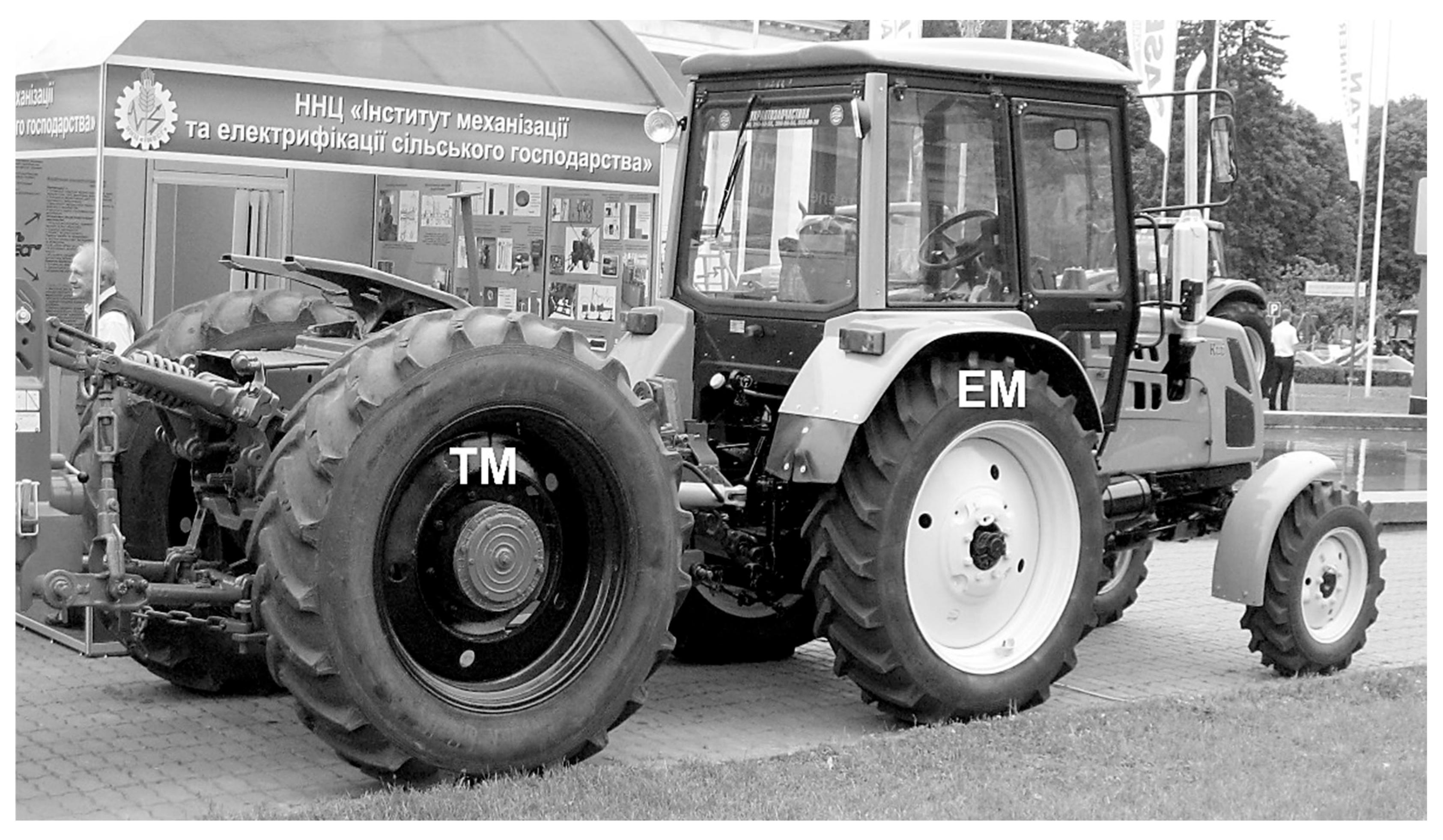
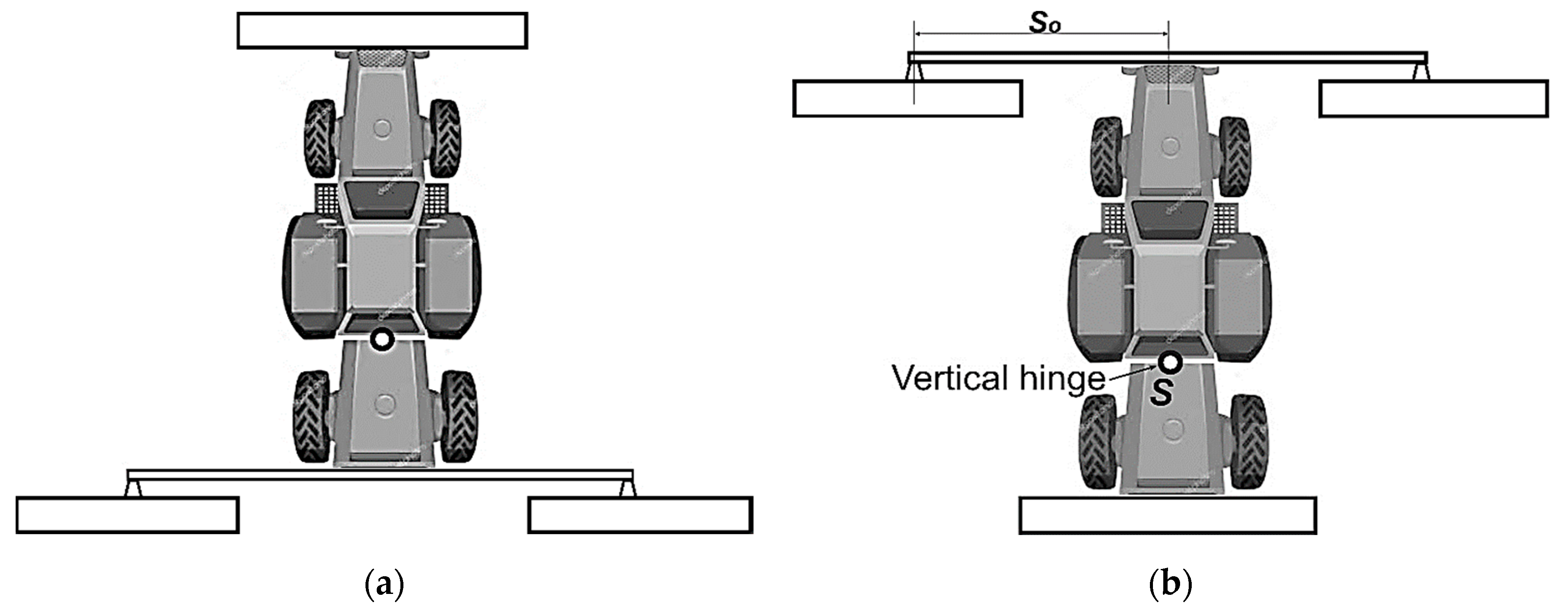
One way to solve this problem is to create modular tractors (
Figure 1). Their design consists of two modules: energy (EM) and technological (TM). EM is a tractor with an increased level of energy saturation. TM is a tractor bridge whose wheels are driven by a synchronous PTO EM (power take-off of high-energy tractor). More detailed characteristics of this modular vehicle can be found in the article [
12].
The operating principle of a modular tractor is that it realizes one part of the engine power through the energy module running system and the remaining part through the technological module’s running system [
13,
14]. Due to the presence of a vertical hinge, the latter can have various options for joining the EM in the horizontal plane. In this case, the vertical hinge of the TM can be in free, locked, and controlled states. Ultimately, this adds a degree of complexity to the modular tractor design, which requires a suitable algorithm to make a reasonable choice [
9,
15]. Theoretically, this requires a mathematical model of the MTU’s operation based on a modular tractor.
It should be noted that, despite their external similarities, the modular tractor differs from conventional three-axle mobile vehicles such as the well-known Trisix Vario or Valmet 1502. In the latter, the third bridge is not a detachable/attachable module, but part of its construction, being rigidly connected to the main tractor frame in the horizontal plane [
16].
Machine-tractor units, in which one of the axes of the used trailed machine is considered a technological module, are also unsuitable for developing the required mathematical model [
17,
18,
19]. Moreover, the above-mentioned publications did not use any mathematical description of the units operating in the horizontal plane. This does not allow us to evaluate the controllability or stability of their plane-parallel movement.
Article [
20] examines the technological module’s influence on the modular tractor traction performance. In particular, the authors’ calculations established that using TM makes it possible to increase the traction force of the entire vehicle by 1.43 times. As for the forces acting on it, their dynamics are not considered in the horizontal or longitudinal–vertical planes.
The results of experimental studies of a modular tractor in a unit with a disc harrow are presented in articles [
21,
22]. The technological module is rigidly connected to the energy module in the horizontal plane. However, the controllability of the unit’s movements and/or stability are not considered.
The theory of unit operation based on a modular tractor is presented in [
23]. It addresses the issue of damping the vertical hinge joining the EM and TM in the horizontal plane. At the same time, neither the free nor the locked state of this hinge is considered in the study. Furthermore, the mathematical model of the unit presented in this work does not consider the frontal or lateral arrangement of agricultural machines. And such MTU diagrams based on a modular tractor, as shown in practice, are promising [
24].
Because of the above, the objective of this article is to model the motion stability of machine tractor units based on a modular tractor.
To achieve this objective, the following tasks were set:
- (1)
to develop a mathematical model of the horizontal movement of the unit based on a modular tractor, reflecting different states of the vertical hinge TM (free, blocked, controlled) with different locations of the agricultural machines (front, side);
- (2)
verification of the adequacy of the developed mathematical model;
- (3)
to study the influence of the TM vertical hinge state on the stability of the unit’s movement based on a modular tractor.
The practical implementation of the article’s objectives allows us to create an adequate mathematical apparatus that will enable us to solve the following scientific problems: (i) to study the stability and controllability of the wide-operating units based on a modular tractor; (ii) to justify the number of machines used with a tractor (from 1 to 3); (iii) to study the controllability and stability of the unit’s movement with simultaneous turning of the EM’s front wheels and the TM frame; (iv) to evaluate the trajectory indicators of the units movement based on a modular tractor with simultaneous turning of its front wheels and the TM ones.
2. Theoretical Premises
It is convenient to consider the agricultural MTU model functioning based on a modular tractor in its reactions to input control and disturbing influences. The indicated responses of the unit in the first case determine the controllability and stability of its movement in the second. In this case, the turning angle of the energy module front wheels (α) is taken as the control action. Concerning the main assumptions and simplifications made in the work, it is assumed that the quantity and nature of the disturbing influences are different for each specific MTU and depend entirely on its design and functional purpose.
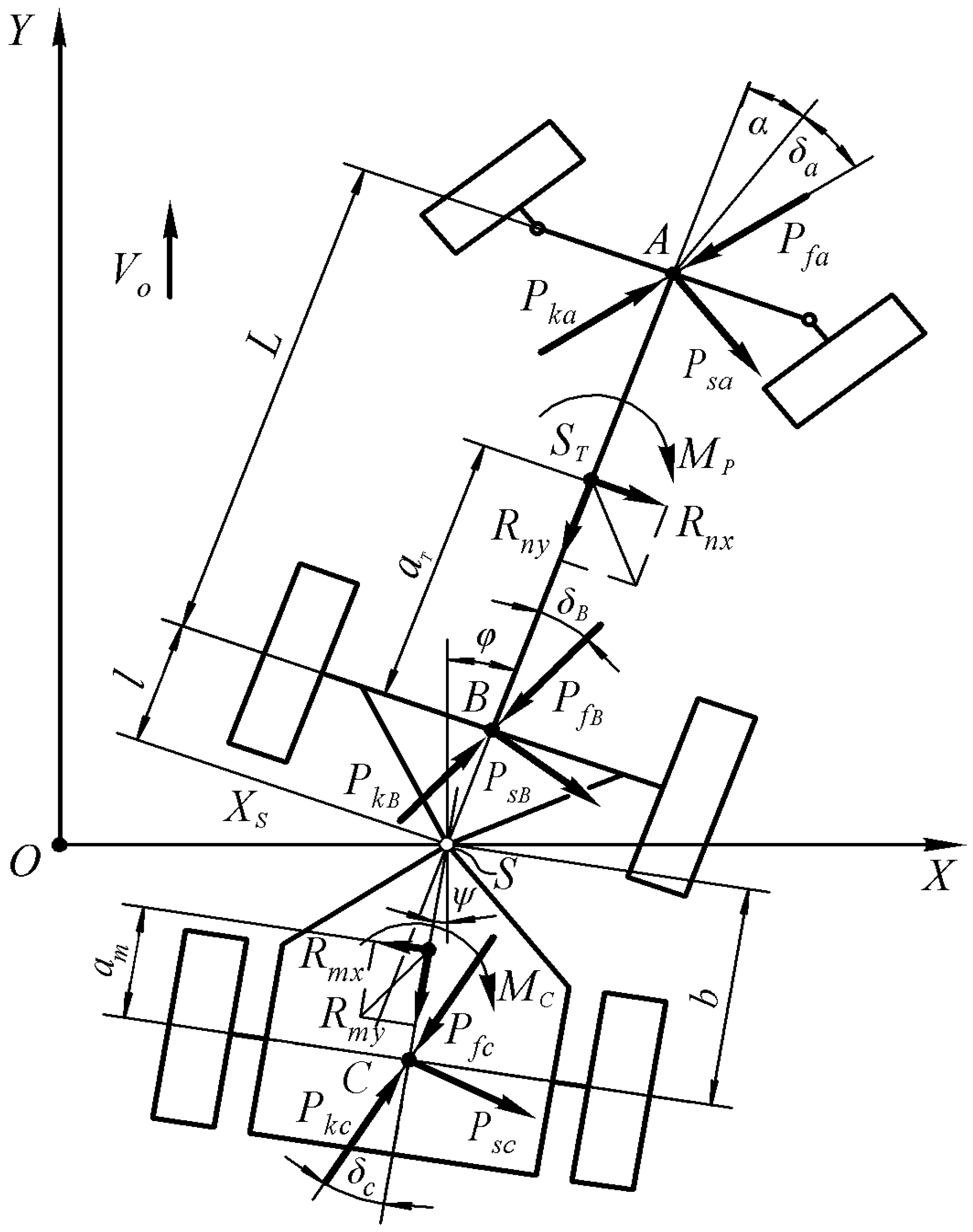
To solve the problem, let us imagine that an MTU based on a modular tractor performs an even translational movement at a
velocity together with the XOY plane (
Figure 2).
In the process of performing work, the energy and technological modules of the tractor, under the influence of random disturbances, deviate from their original positions and receive additional velocities. At the same time, EM turns in the XOY plane through an angle φ. The mass center of the entire tractor (point S), located on the axis passing through the vertical hinge of the TM, moves in the transverse direction by an amount determined by the coordinate. The technological module performs an independent turning movement, the measure of which is the angle ψ.
Thus, an MTU based on a modular tractor with a free vertical hinge TM and front-steered wheels in the horizontal plane has three degrees of freedom, corresponding to three generalized coordinates:
φ and
ψ angles, and the
abscissa. The number of external forces acting on the MTU under consideration during its plane-parallel motion includes rolling resistance forces of the front (
) and rear (
) EM wheels and TM wheels (
; gross traction forces of three tractor axles
and
; lateral forces
and
leading to the emergence of yaw angles (
δa,
δb, and
δc) of the front and rear axles of the energy module and the bridge of the technological module, respectively; the components of the main vector of forces (
) reduced to the EM mass center, as well as the central moment of forces
acting from the front and side agricultural machines (diagram A,
Figure 3); components of the main vector of forces (
) reduced to the TM mass center and the central moment of forces
, acting from the rear and side machines (diagram B,
Figure 3).
As noted above, the joining of the technological module to the energy one in the horizontal plane can be either locked or hinged. Both design solutions provide at least three options for controlling the direction of the MTU operating movement based on this modular tractor (
Table 1).
From the point of view of technical feasibility, option 1 is the simplest since eliminating the angular mobility in the horizontal plane of the technological module relative to the energy one (option 1a) does not present any particular difficulty. From the standpoint of mathematical description, option 1b, due to the presence of an additional degree of freedom in the form of the TM turning angle
(ψ), is the most complex. But since this is the most general case of a modular tractor diagram, from the MTU motion equations based on it, through appropriate transformations, mathematical models of units that implement all other methods of controlling a modular tractor listed in
Table 1 can be obtained.
In order to simplify the calculations for building the mathematical model, it was assumed that at small angles of rotation of the front wheels of the energy module tg(α) = α. This assumption led to a slight discrepancy in the units of measurement in the final formulas of the system of Equation (1).
The mathematical model of MTU movement based on a modular tractor with the free state of the TM’s vertical hinge (point S) has the following form:
where:
The equations system (1) uses the following notation: , —mass of EM and TM, respectively, kg; , —moments of inertia EM and TM in the horizontal plane, kg·m2; , , —coefficients of resistance to tyres yaw of EM and TM wheels, respectively, N/rad; L—wheelbase of EM, m; ,—longitudinal coordinates of the EM and TM mass centers, m; , —distances from the axis of the TM vertical hinge to the axis of the rear wheels EM and TM, respectively, m.
The locked joining of the technological module to the energy one in the horizontal plane means that:
In the case of controlling the movement of a modular tractor by turning the front wheels EM and simultaneously turning the TM frame (option 3b,
Table 1), the following conditions are valid:
where
is the coefficient of proportionality between the EM’s steered wheels’ turning angle and the technological module frame turning angle relative to the energy one.
A mathematical model of an MTU based on a modular tractor controlled by simultaneous turning of the energy module front wheels and the wheels of the technological module (option 2a,
Table 1) can also be obtained from (1). To do this, the original system of differential equations should be rewritten, taking into account the conditions in (3) and a slightly modified equation for determining the yaw angle of the TM axis:
where
k·α—TM wheels angle turning.
The equations for determining the components of the main vectors of forces and moments included in the right parts of the system (1) have the form:
where , —lateral displacement resistance coefficients of front and rear machines, respectively, H/rad; , —distances from the resistance centers of the front and rear machines to the EM and TM mass centers, respectively, m; —the distance along the front between the resistance center of the lateral (front or rear) machine and the MTU symmetry longitudinal axis, m; —difference in traction resistance of the MTU’s side (left and right) machines, N.
3. Materials and Methods
The subject of the study is modeling the motion stability of machine-tractor units based on a modular tractor.
The study’s main hypothesis was that blocking the TM vertical hinge could significantly increase the motion stability of the wide-width MTU based on a modular tractor.
To check the adequacy of the MTU mathematical model based on a modular tractor (
Figure 1), we used a unit assembled according to diagram A (
Figure 3). The KIY-14102 tractor (Ukravtozapchastina LLC, Kyiv, Ukraine) was used as an energy module (
Table 2).
The modular tractor was used with three KRN-4.2 cultivators (Elvorti, Kropyvnytskyi, Ukraine) designed for inter-row cultivation of row crops with row spacing of 70 cm. According to diagram B (
Figure 3), one cultivator was hung behind the EM. Two other cultivators were connected to the front linkage of the energy module using a semi-mounted hitch.
When operating movement, the vertical hinge, which joins the EM and TM, was automatically locked by a unique device. It unlocked when driving on the headland. This allowed the TM and the side machines to turn relative to the EM and realize the movement of the MTU with a minimum radius. Moreover, since this modular tractor has parameters
l = b (see
Table 2), the TM wheels moved along the tracks of the EM rear wheels on the headland. In this case, the TM did not limit the agility of the EM.
A modular machine-tractor unit was studied for inter-row processing of sunflower seedlings. Two sites were allocated on the field, each 250 m long. The first 25 m of the site was used to overclock the MTU. Measurements were carried out on the remaining part (225 m). In the process of field research, the following were recorded: heading angle MTU (φ); EM’s wheels steering angle (α); traction resistance (N) of cultivators KRN-4.2 (); time (t) for the MTU to pass the test site.
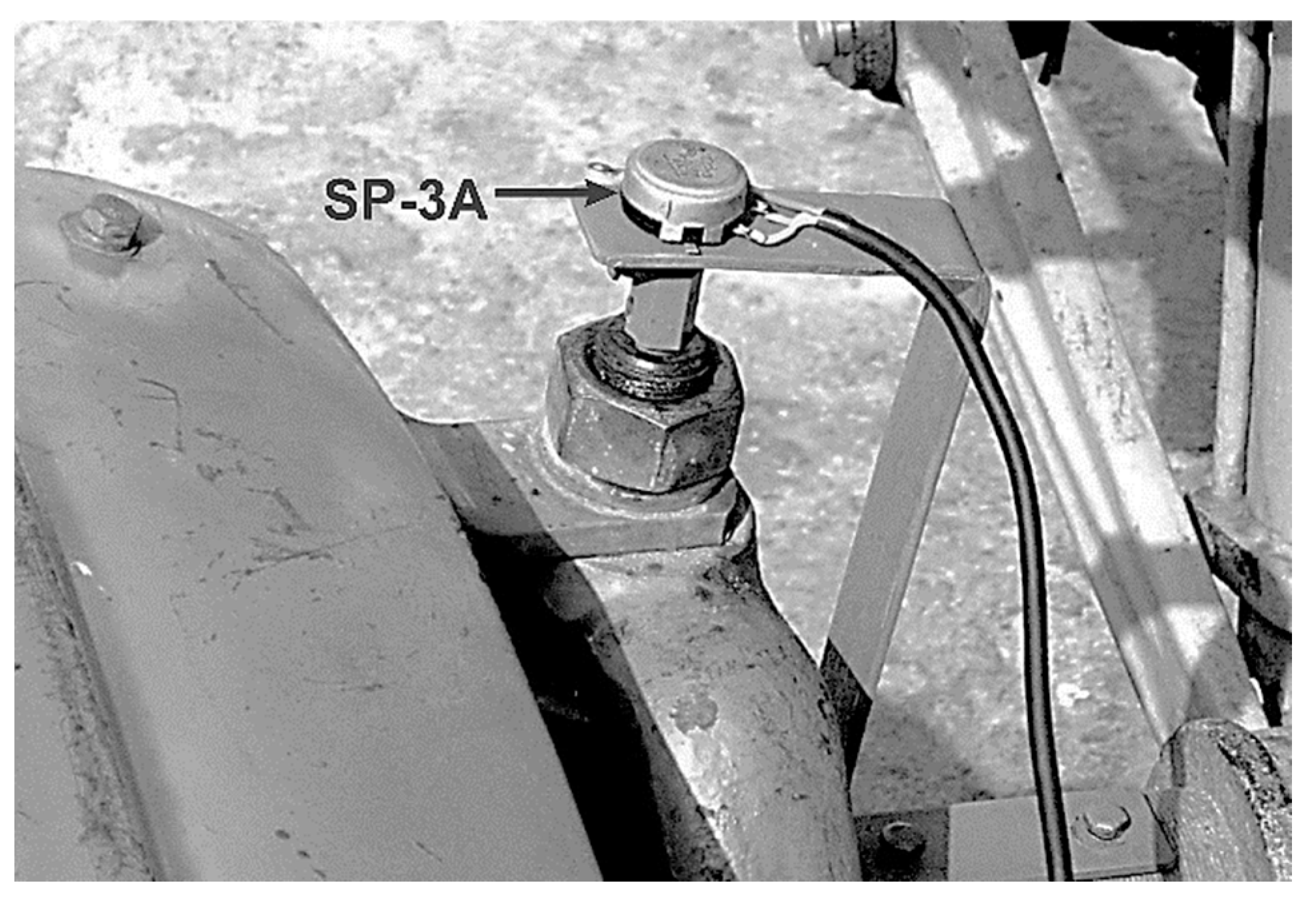
To measure the angle
α, a variable SP-3A resistor (Daier, Liushi Town, Yueqing City, Zhejiang, China) with a nominal value of 470 Ohms and a linear characteristic was used. It was installed on the kingpin axis of the left front EM wheel (
Figure 4).
The heading angle φ was recorded using a GY-521 6DOF gyroscope on an MPU-6050 chip (TDK InvenSense, San Jose, CA, USA). Hanging frames with strain gauge elements were used to record the traction resistance of cultivators, which made it possible to record traction resistance of up to 30 kN. The unit’s time passed the test section was recorded with an electronic stopwatch PC 396 (Hefei Strong Sports Co., Ltd., Anhui, China) with a measurement accuracy of 0.01 s. The measurement data determined the MTU movement velocity using the formula = 225/t (m/s).
Electrical signals from the variable resistance, gyroscope, and strain gauge elements were recorded using an Arduino Uno device (Arduino S.r.l, Monza, Italy). The obtained data were used to calculate the parameters’ variances and normalized spectral densities α, φ, and .
The measurement error of the α parameter did not exceed 1o, the parameter—no more than 0.5%, and the φ parameter—less than 2%.
Testing the model for adequacy consisted of comparing the actual (obtained experimentally) normalized spectral density of the heading angle (
) with the theoretical one (
). The latter was determined from the equation [
25]:
where
,
—amplitude–frequency characteristics (AFC) of the MTU relative to its heading angle under control (angle
α) and disturbing (difference in traction resistance of side cultivators) influences, respectively;
,
—normalized spectral densities of
α and disturbing influence, respectively, s;
,
—variances of oscillations of
α and
φ parameters, rad
2;
—variance of oscillations of the difference in MTU side cultivators’ traction resistance, N
2.
AFCs of the unit (
,
) were obtained from the mathematical model (1) using condition (2) according to the method described in [
26,
27]. In the case of an acceptable agreement between (
) and (
, the developed mathematical model was considered suitable for subsequent analysis of the MTU movement stability.
4. Results and Discussion
During the experiment, the unit under study moved in the forward and reverse directions at a mean velocity of 2.05 m∙s
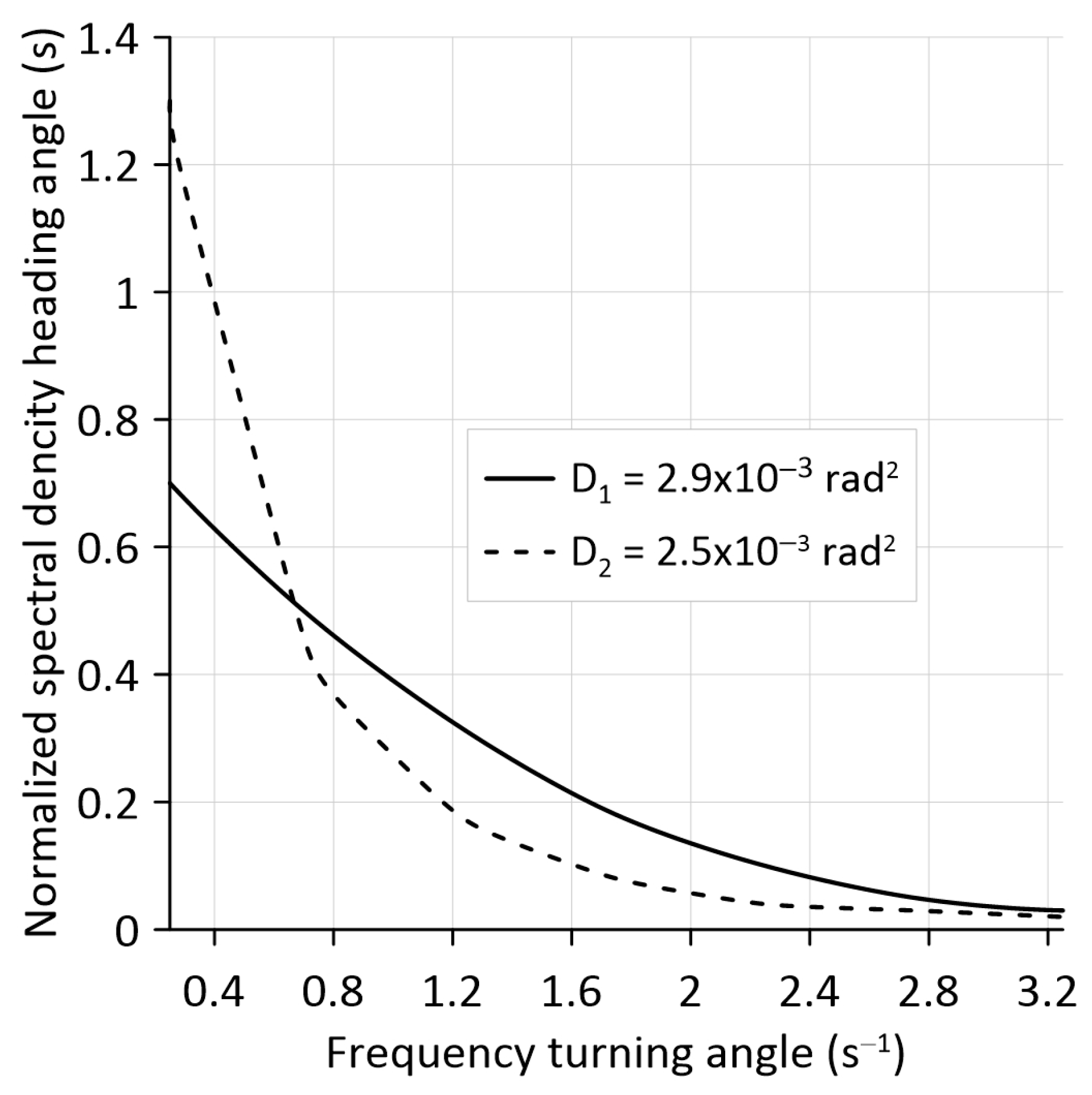
−1. Analysis of the data obtained showed the following. MTU heading angle oscillations’ theoretical and experimental normalized spectral densities have the same cut-off frequency of 3.2 s
−1 (
Figure 5).
In both cases, the maximum variance values of the
φ parameter oscillations also occur at the same frequency, being equal to 0.25 s
−1. A F-test comparison of the values of the obtained variances showed the following. The actual value of this statistical indicator is = 2.9 × 10
−3/2.5 × 10
−3 = 1.16. Its tabulated value (
), accepted for a statistical significance level of 0.05, equals 1.39 [
28]. Since
<
, with a confidence probability of 95%, it can be stated that the null hypothesis about the equality of the compared variances is not rejected. The resulting arithmetic difference between the values of these statistical parameters is random and insignificant.
As a result, we found that both in terms of frequency composition and variance, the theoretical and experimental normalized spectral densities represent the same general population of data. This indicates the adequacy of the developed mathematical model (1). It can then be used to adequately analyse the modular tractor-based MTU’s driving stability.
During the modeling process, the moment (N·m) created by the difference in traction resistance (
, N) of the side cultivators at a distance
(
Figure 3b) was taken as a disturbing influence on the MTU. The output parameter of the dynamic system under consideration is the heading angle of the machine-tractor unit (
φ).
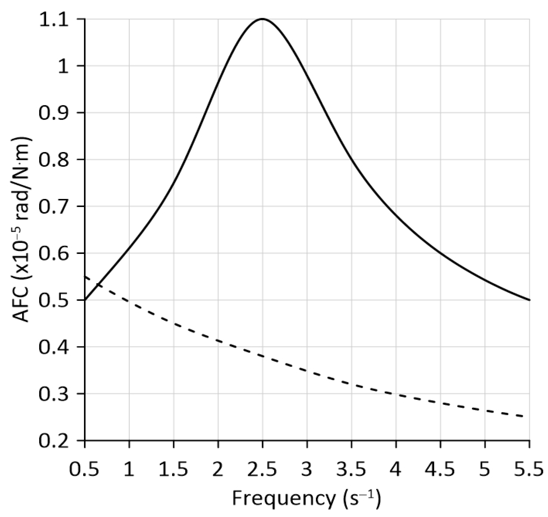
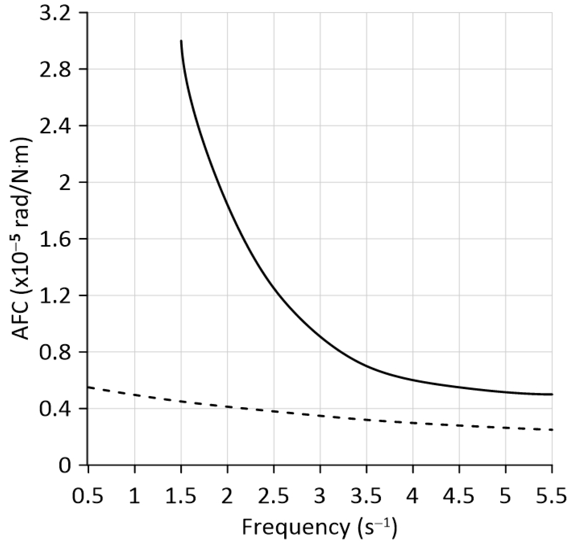
Analysis of the amplitude–frequency characteristics obtained during modeling showed the following. When the vertical hinge of the TM is in a free state (see
Figure 3b), AFC has a clearly manifest maximum, which occurs at a frequency of 2.5 s
−1 (
Figure 6).
Blocking the vertical hinge leads to an increase in the longitudinal base of the modular tractor. When this joint is free, the turning moment
acting from the side cultivators (see
Figure 3b) is mainly opposed by EM. Its wheelbase (
L) is 2.40 m (
Table 2). When the TM hinge is locked, the EM and TM resist the action of the specified turning moment. Their longitudinal base (
= 2.40 + 1.30 + 1.30 = 5.00 m) increases by 2.08 times. As a result, the AFC of a modular tractor has significant differences. Firstly, it does not have any resonant peaks at all. Secondly, its value, starting from the disturbance frequency of 0.65 s
−1, is significantly less. The obtained result is desirable based on the following considerations. When working out a disturbing influence (i.e., interference), the best is the AFC, which has smaller values. The ideal AFC in the entire frequency range of the disturbance is 0 [
23].
Further, in the zone of the resonance peak, the AFC of the unit with a free hinge of the technological module is equal to 1.1 × 10
−5 rad/N·m (
Figure 6). If the hinge is blocked, the AFC value decreases to 0.39 × 10
−5 rad/N·m, that is, 2.82 times. Let us express this result through changes in the heading angle
φ. While checking the mathematical model (1) for adequacy, we found that the maximum value of the difference in resistance of the MTU’s side cultivators (
) was approximately 1000 N. Since this MTU = 4.2 m, the value of the turning moment
was 4200 N·m. The influence of the latter with a frequency of 2.5 s
−1 and its amplification level of 1.1 × 10
−5 rad/N·m causes a change in the heading angle of the MTU with a free TM hinge by an angle of approximately 3°. When the hinge is blocked, the impact of the same turning moment with the same frequency but with a gain level of 0.39 × 10
−5 rad/N·m, leads to a change in the parameter
φ by only 1°, i.e., 3 times less.
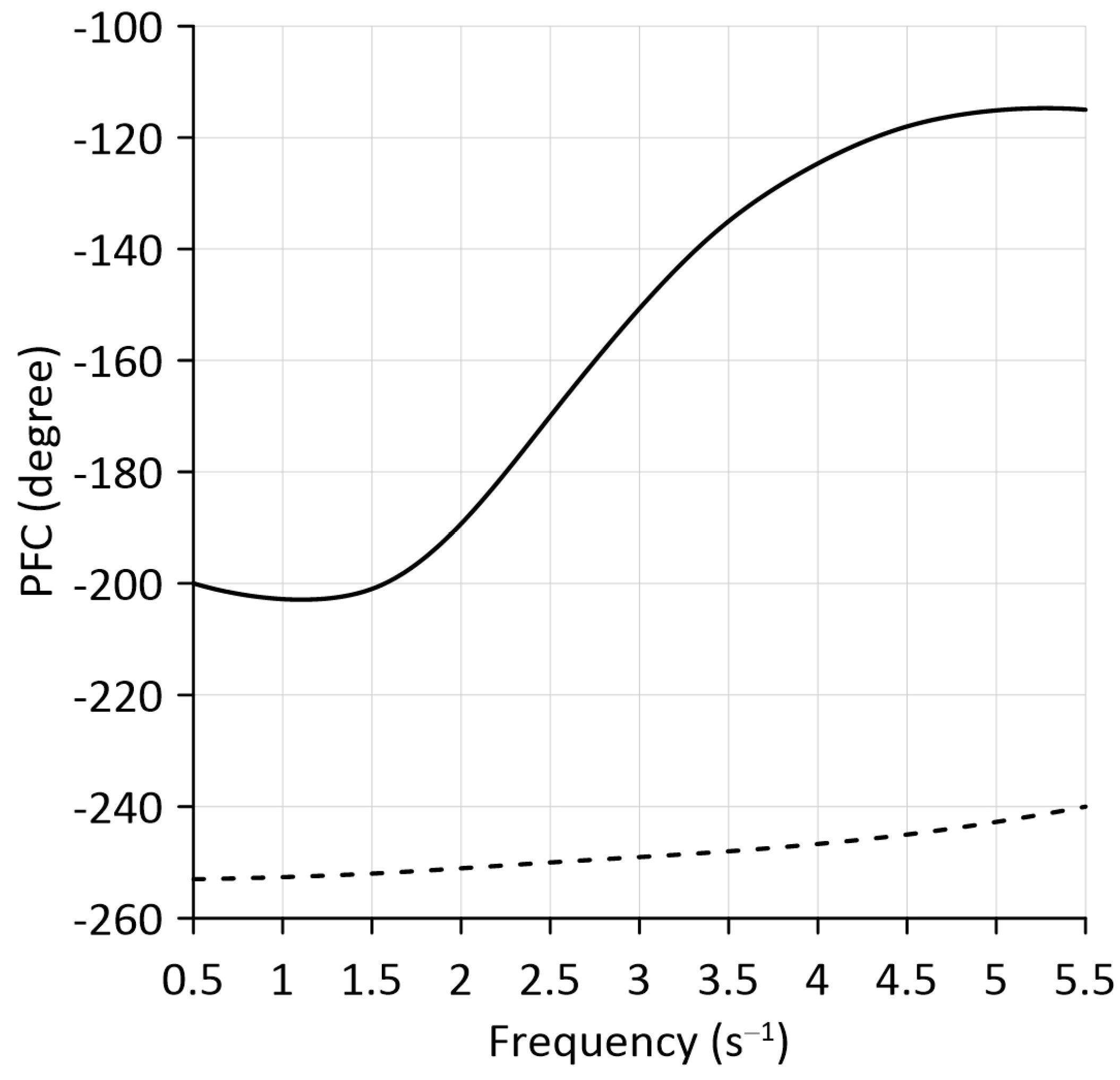
In addition to AFC, phase frequency response (PFC) is an important characteristic of a dynamic system. They show the delay in the system’s response to input influences. When working out the disturbing influence, the ideal PFC should tend to infinity [
23,
29]. In other words, the later a dynamic system reacts to a disturbance, the better.
In the case we are considering, with the vertical hinge TM in a free state, the phase shift in the unit’s processing of the turning moment
has the shape of a logistic curve (
Figure 7). In this case, the phase shift in the MTU response to disturbance does not exceed −202°.
Blocking the vertical hinge of the TM contributes to an increase in the phase shift in the response of the dynamic system by −240° or more. At the same time, the growth rate of this process is significantly lower than that of the version with a free state of the TM hinge. As a result, we observed the following pattern. When the oscillation frequency of the external disturbance increases by more than 1.5 s−1, the difference between the obtained PFCs (ΔPFC) increases.
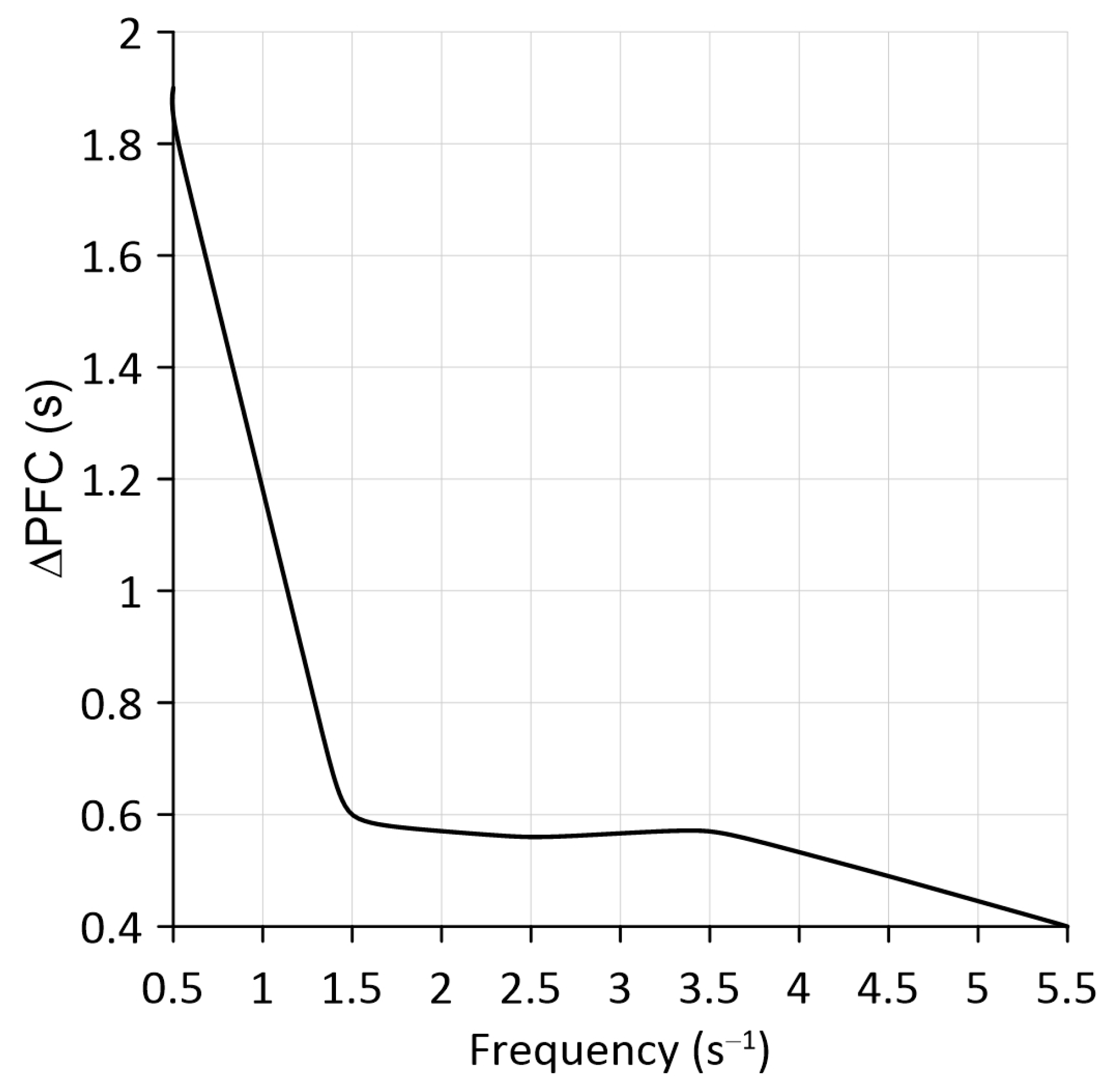
However, such an assessment of the resulting PFCs is not entirely convenient. It is more practical and visually convenient to represent the difference ΔPFC in terms of time (s). It is defined as follows:
where
ω—oscillations frequency of the disturbing influence—moment
(s
−1).
Analysis of the process Δ
PFC =
f(
ω) showed the following: At
ω = 0.5 s
−1, blocking the vertical hinge of the TM increases the delay in the MTU response to fluctuations in the disturbing moment
by 1.9 s, which is a significant result (
Figure 8).
The subsequent increase in the oscillation frequency of the external disturbance to a value of 1.5 s−1 is represented by a decrease in the difference ΔPFC to 0.6 s. A slight drop in the value of the ΔPFC parameter characterizes a further increase in ω.
According to our research, at least 95% of the variance in the different oscillations in traction resistance of side machines, aggregated with the modular tractor, is concentrated in the frequency range 0–0.6 Hz or 0–3.7 s
−1. As we can see, this frequency range fits nicely into the one considered in this analysis (0–5.5 s
−1). Considering this fact and the data from
Figure 6 and
Figure 8, we can conclude that blocking the TM’s vertical hinge is advisable to increase the movement stability of wide-width MTUs based on a modular tractor.
It should be noted that, unlike a three-axle (or multi-axle) vehicle, the result obtained for a modular tractor is not obvious and therefore requires study. For specific values of the
parameter (
Figure 3), the sum of the values
(
Figure 1), the mass of the machines used, etc., the blocking of the vertical hinge TM may be insufficient. In this case, an appropriate analysis is required using the mathematical model (1).
In principle, the mathematical model (1) allows one to estimate the MTU movement stability based on only one energy module (i.e., without TM). To do this, in the system of Equation (1), it is necessary to remove (that is, equate to zero) all those forces, moments, and design parameters associated with the presence of a technological module. It should be noted that the traction capabilities of the KIY-14102 tractor, when ballasted with a weight of 500 kg, allow it to be independently aggregated with three cultivators of the KRN-4.2 type. But calculations show that, in this case, there may be a problem with such unit movement stability. This is especially problematic at low oscillation frequencies of the disturbing torque.
As the analysis of the obtained AFC (
Figure 9) shows, already at
ω = 1.5 s
−1, the amplification coefficient of the external disturbance by the unit based on KIY-14102 (without TM) is 3.0 × 10
−5 rad/N·m. With the above-mentioned value of the turning moment
= 4200 N·m, this will cause such a unit to turn at an angle of 0.126 rad or 7.2°. This means a complete loss of the unit’s movement controllability in the horizontal plane.
At the same time, when the same disturbing influence is processed at the same frequency (1.5 s−1) by a unit based on a modular tractor (KIY-14102 + TM), the deviation of the unit heading angle will be only 1.1°. The tractor driver can quickly correct such deviation of the MTU from the course. Moreover, there is no deterioration in the quality of the technological process.


 ,
, 
