Article

A Generalized Shape Function for Vibration Suppression Analysis of Acoustic Black Hole Beams Based on Fractional Calculus Theory

1
College of Intelligent Manufacturing, Anhui Vocational and Technical College, Hefei 230013, China
2
College of Mechanical and Electronic Engineering, Nanjing Forestry University, Nanjing 210037, China
*
Authors to whom correspondence should be addressed.
Appl. Sci. 2025, 15(5), 2768; https://doi.org/10.3390/app15052768
Submission received: 26 January 2025 / Revised: 22 February 2025 / Accepted: 3 March 2025 / Published: 4 March 2025

Abstract

:
In this paper, a generalized acoustic black hole (ABH) beam covered with a viscoelastic layer is proposed to improve the energy dissipation based on the double-parameter Mittag–Leffler (ML) function. Since fractional-order constitutive models can more accurately capture the properties of viscoelastic materials, a fractional dynamic model of an ABH structure covered with viscoelastic film is established based on the fractional Kelvin–Voigt constitutive equation and the mechanical analysis of composite structures. To analyze the energy dissipation of the viscoelastic ML-ABH structures under steady-state conditions, the wave method is introduced, and the theory of vibration wave transmission in such non-uniform structures is extended. The effects of the fractional order, the film thickness and length, and shape function parameters on the dynamic characteristics of the ABH structure are systematically investigated. The study reveals that these parameters have a significant impact on the vibration characteristics of the ABH structure. To obtain the best parameters of the shape function under various parameters, the Particle Swarm Optimization (PSO) algorithm is employed. The results demonstrate that by selecting appropriate ML parameters and viscoelastic materials, the dissipation characteristics of the structure can be significantly improved. This research provides a theoretical foundation for structural vibration reduction in ABH structures.

1. Introduction

A black hole is a concept in astrophysics that is characterized by not allowing matter and radiation to escape from its boundary. After years of research, scholars found that there are similar phenomena in the fields of acoustics and vibration, and proposed the concept of an acoustic black hole (ABH) [1]. In 1988, Mironov [1] found a similar black hole phenomenon in the wedge-shaped structure whose thickness satisfies the power-law profile. The wave velocity on the structure can be smoothly attenuated to zero, resulting in energy residence. However, due to the limitation of manufacturing capacity, the ABH structure must be truncated at the end, which results in the reflection of bending waves at the terminal, and the perfect ‘black hole’ performance cannot be obtained. Therefore, it is necessary to add energy-consuming devices to the original ABH substrate, such as a viscoelastic material layer [2].
ABH structures can control flexural waves and have great application potential in the engineering field, and their application has attracted the extensive attention of researchers around the world. Structural vibration attenuation, sound attenuation, and energy harvesting can be achieved by designing ABH structural configurations and selecting appropriate materials. There is a wealth of research on ABH structures. Li and Ding [3] studied the sound radiation performance of a beam with wedge-shaped edge embedding ABH features. Huang et al. [4] presented a novel design and implementation of a one-dimensional (1-D) functionally graded ABH structure, and they investigated the wave reflection effect of the ABH structure. By adding energy acquisition device in the ABH part, the vibration energy can be collected. Li and Ding [5] investigated the vibration energy concentration performance of a 1-D wedge-shaped ABH structure. Ji et al. [6] designed an energy-harvesting device with various ABH features to enhance energy-harvesting performance. Deng et al. [7] investigated the energy-harvesting capability of an ABH piezoelectric bimorph cantilever. Zhang et al. [8] established a fully coupled electromechanical model of PZT-coated ABH beams for investigating the resultant energy conversion efficiency of the structure. Li et al. [9] designed a unimorph piezoelectric cantilever equipped with ABH termination for energy harvesting in a wide frequency band. ParK and Jeon [10] designed an ABH with a concave shape to facilitate the focusing of elastic waves at the tip region with higher energy density and to minimize the structural vibrations. Yang et al. [11] proposed a quasi-periodic additional ABH piezoelectric beam structure for efficiently recovering low-frequency broadband energy and improving the issue of structural strength reduction.
The ABH beam structure is a special case of non-uniform beams, so the commonly used non-uniform beam analysis methods can be introduced into the analysis process of ABH structure, such as the Rayleigh–Ritz procedure [12], the Gaussian expansion method [13], and the block transfer matrix method [14]. In addition, scholars have proposed some new analytical approaches to analyze vibration characteristics and optimize the design of ABH structures, such as a semi-analytical method combining the Rayleigh–Ritz method with the Gaussian trial function [15], a semi-analytical method based on Finite Element Method [16], the spectral element method [17], the power series expansion method [18], and the multiscale Gaussian expansion method [19]. These methods help us to gain insight into the dynamic and static properties of ABH structures and their optimal design.
Although the ABH structure has many advantages, there are drawbacks. The energy attenuation performance of ABH structures with a viscoelastic layer is weak in the low-frequency range. To overcome this drawback, scholars have carried out relevant research. Gao et al. [20] designed a V-folded ABH beam to reduce bandgap frequencies. Li et al. [21] investigated broadband vibration mitigation properties of ABH beams equipped with four types of dampers. Zhang et al. [22] designed an ultralight phononic beam composed of a complex lattice of ABH to achieve broad low-frequency bandgaps (BGs). Gao et al. [23] introduced ethylene vinyl acetate material into a composite ABH beam to investigate the low-frequency elastic wave attenuation properties. Zhang et al. [24] designed a lightweight and high-stiffness beam insulator embedded in a graded double-leaf ABH for vibration reduction in the low-frequency range. In addition, the application of ABH structure is greatly affected by the spatial distribution position. To avoid the limitation of space size on the application of ABH, scholars have proposed spiral ABH structures, such as the Archimedean spiral configuration [25] and helix-acoustic configuration [26].
Since viscoelastic materials are added to the ABH structure to achieve vibration reduction properties, the fractional calculus theory can describe the properties of viscoelastic materials better than the integer theory [27,28]. For now, there are many research results of uniform beam and non-uniform beam structures based on the fractional calculus theory. Oskouie and Ansari [29] investigated the linear and nonlinear vibration analysis of viscoelastic Timoshenko nanobeams based on fractional calculus theory. Xu et al. studied the vibration problems of viscoelastic beams [27] and viscoelastic sandwich beams [28] based on the fractional calculus theory. However, to the authors’ knowledge, there is limited research on dynamic models of viscoelastic ABH beams described by fractional-order theory. Current research on fractional-order models for ABH structures primarily focuses on incorporating fractional-order boundary conditions and fractional-order acoustic fields [30], rather than introducing fractional calculus theory based on perspective constitutive modeling or ABH composite structure properties. Consequently, a fractional-order vibration model of the ABH composite double-layer beam is studied and established in this paper.
Moreover, the vibration analysis methods for the ABH structure mentioned above are incapable of analyzing the vibration characteristics of the fractional-order ABH beam model. To derive the steady-state solution for the vibration of a fractional-order non-uniform beam, the wave method is introduced within the context of this paper. The theoretical framework of the wave method is extended, and a recursive formulation is derived to characterize the vibrational behavior of such structures. Power-law ABHs might exhibit even narrower bandwidths. The power-law profile might be optimized for a specific frequency, leading to poor performance outside that range [14]. Furthermore, from a mathematical perspective, the Mittag–Leffler (ML) function, though lesser-known, exhibits broad variational flexibility and serves as a generalized function. Owing to its parsimonious parameterization, diverse curve morphologies can be generated through parametric optimization, thereby enabling efficient identification of configurations that enhance the vibration attenuation performance of ABH structures. Therefore, a generalized ABH shape function is proposed, namely the two-parameter ML function, to expand the bandwidth range for vibration reduction and enhance the energy dissipation properties of ABH structures with viscoelastic layers. It is noteworthy that the proposed shape function exhibits generalized characteristics, allowing the vibration damping performance of the ABH structure to be optimized through parameter tuning. Furthermore, compared to power-law functions (m = 2 and 4), the ML-shaped function achieves superior vibration attenuation with reduced material consumption. Due to the significant impact of ML parameters on the vibration reduction characteristics of ABH structures, we introduced the Particle Swarm Optimization (PSO) algorithm to obtain the optimal parameters for achieving the best vibration reduction characteristics.
The rest of this manuscript is organized as follows: In Section 2, the fractional-order model of a viscoelastic ABH beam structure with a cladding layer is established and the vibration wave transmission formula and iterative calculation formula for analyzing such non-uniform ABH structures using the wave method are derived in this part. Section 3 validates the effectiveness of the wave method in vibration analysis of the ABH structure. In Section 4, a generalized ABH shape function is proposed, namely the two-parameter ML function. In addition, the influence of the two parameters of the shape function on the shape of the ABH structure is analyzed. In Section 5, the influence of the fractional order, film thickness, and length on the energy dissipation properties of the fractional ML-ABH beam is analyzed. To achieve the best vibration reduction performance, the PSO algorithm is introduced to obtain the optimal shape function parameters for different film thicknesses, lengths, and fractional orders. Section 6 discusses the results.

2. Fundamental Theory

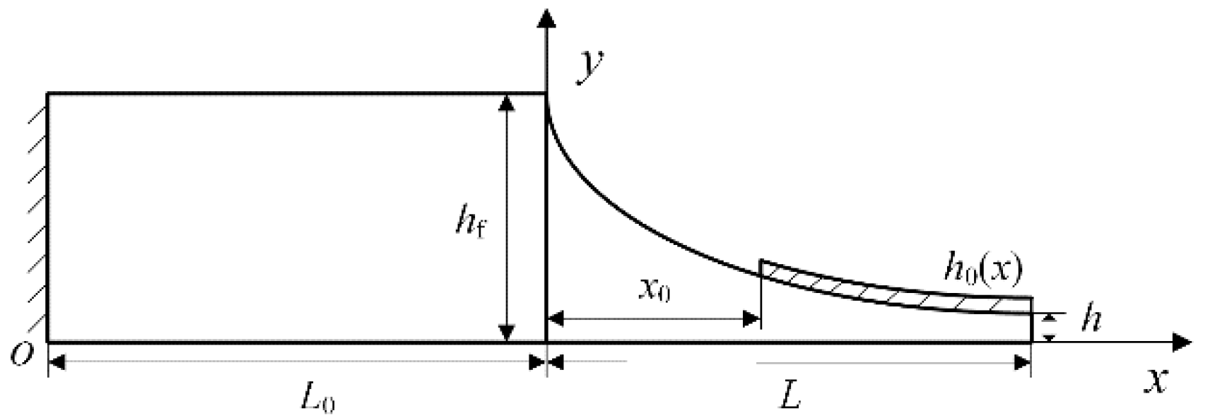
2.1. The Vibration Equation of Traditional ABH Structure

Conventional ABH beams are non-uniform structures and their equation of shape is usually a quadratic function. The detailed dimensions of each part of the structure are shown in Figure 1. L0 and L are the length of the part with an equal cross-section and ABH part, respectively. The heights h(x) of the ABH part satisfied the following quadratic function:
h x = ε a x m , 0 x L ,
The vibration equation of the whole structure is
E I x 4 w x 4 + ρ A x 2 w t 2 = q x , t ,
where E is the elastic modulus of the structure; ρ is the density of beam; A(x) is the cross-sectional area; q(x, t) is the distributed force; w = w(x, t) is the lateral displacement; I(x) denotes sectional moment of inertia.
I x = 1 12 b h 3 ( x ) .
where b is the width of the beam and h(x) is the height of the ABH structure.

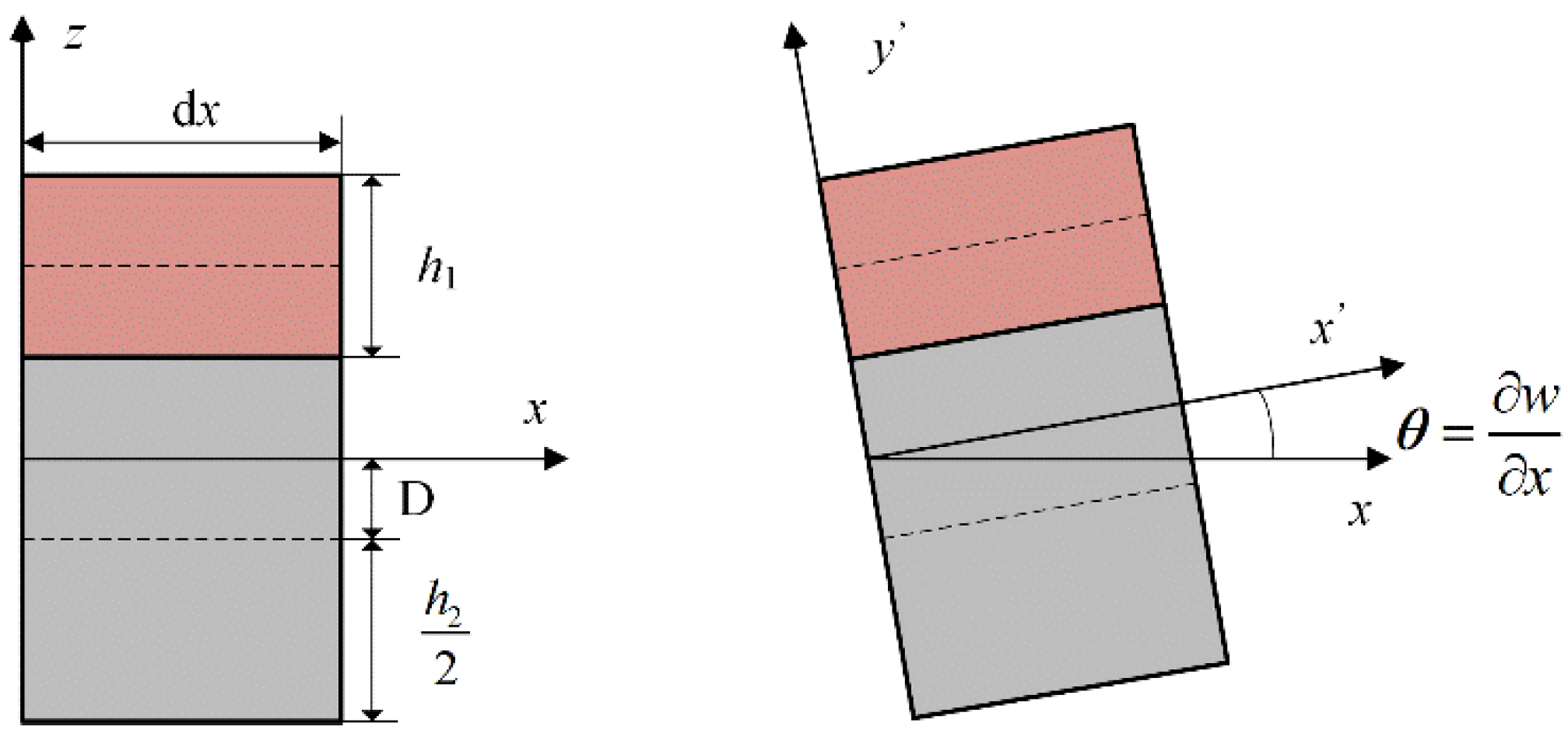
2.2. A Generalized Fractional-Order Model for Viscoelastic ABH Composite Beams

The structure consists of equal-thickness viscoelastic and inhomogeneous layers, as shown in Figure 2. L is length of the ABH part, L0 is the length of the uniform part, x0 represents the uncoated length on the ABH part, h denotes the terminal thickness of the ABH part, hf is the thickness of an initial section of the ABH part, and h0(x) is the coating thickness. Since fractional-order constitutive models can more accurately capture the properties of viscoelastic materials, a generalized fractional dynamic model for viscoelastic ABH composite beams is proposed.
The deformation form of the two layers can be approximately considered to be consistent because the upper membrane surface is soft relative to the base. In the modeling process, the whole structure is divided into a series of micro-segments, each of which is a uniform structure. It is assumed that the approximate deformation form of a micro-fracture of the structure is shown in Figure 3.
According to the classical theory, the displacement field of the composite beam under small deformation is as follows:
u 1 x , z , t = z w x ,     h 2 2 D z   h 2 2 D + h 1 u 2 x , z , t = z w x ,     h 2 2 D z   h 2 2 D ,
where u1(x, z, t) is the displacement of the coating layer, u2(x, z, t) represents the thickness of the base layer, w is the lateral displacement of the midplane of the beam, z denotes the distance from the plane to the neutral plane, and D is the distance from the neutral plane to the midplane of the base. The corresponding strain relationship can be obtained from the displacement of each layer:
ε i x , z , t = u i x , z , t x ,     i = 1 , 2 ,
Since the material of the upper surface is viscoelastic material, fractional calculus is very suitable for describing the properties of it due to its genetic memory characteristic. In addition, many studies [27,28] show that fractional calculus theory is very suitable to describe the properties of viscoelastic materials. It is assumed that the stress–strain relationship of viscoelastic material satisfies the fractional Kelvin–Voigt constitutive model, and the stress–strain relationship of the base material satisfies Hooke’s law; the equations of the strain–stress relationship are as follows:
σ 1 x , z , t = E 1 ε 1 x , z , t + η 1 d α ε 1 x , z , t d t α ,     h 2 2 D z   h 2 2 D + h 1 σ 2 x , z , t = E 2 ε 2 x , z , t ,     h 2 2 D z   h 2 2 D ,
where E1 and E2 are the elastic modulus of the viscoelastic material and the base material, respectively; η1 is the comprehensive damping coefficient and α is the fractional order. The α-order (0 < α < 1) fractional derivative satisfied the RiemannLiouville definition. The entire membrane-covered beam has no axial external force, and the following formula is obtained:
Σ F = h 2 / 2 D h 2 / 2 D σ 1 d A 1 + h 2 / 2 D h 2 / 2 D + h 1 σ 2 d A 2 = 0 ,
Therefore, the distance D is as follows:
D = E 1 2 w x 2 + η 1 α t α 2 w x 2 h 1 h 2 + h 1 2 2 E 2 2 w x 2 h 2 + E 1 2 w x 2 + η 1 α t α 2 w x 2 h 1 ,
The bending moment M on the membrane-covered beam section is the sum of the bending moments of each layer:
M x , t = h 2 D h 2 D z σ 2 x , z , t d A h 2 D h 2 D + h 1 z σ 1 x , z , t d A ,
Due to the force and bending moment balance on the micro-fracture, the vibration dynamic equation of the beam can be derived:
2 M x ,   t x 2 + ρ A x 2 w t 2 = q x ,   t ,
where q(x, t) is external excitation; ρA(x) = ρ1A1(x) + ρ2A2(x); ρ1 and ρ2 are the density of the film coverage and base material; A1(x) and A2(x) are the cross-sectional areas of the film coating and the base. Substituting Equations (5) and (8) into (9), the fractional dynamic equation of the composite beam structure is obtained as follows:
E 2 b H h h x 4 w x 4 + E 1 b H h x 4 w x 4 + η 1 b H h x α t α 4 w x 4 + ρ A x 2 w t 2 = q x ,   t ,
where Hhh and Hh are
H h h x = h 2 3 x 12 + h 2 x D 2 H h x = h 2 x 2 D 2 h 1 x + h 2 x 2 D h 1 2 x + h 1 3 x 3 ,
The vibration equation for the uncoated length range (0 ≤ x < x0) on the ABH is given by Equation (2), while the vibration equation for the coated length range (x0xL) is described by Equation (10). In conclusion, the vibration equation of the whole structure is
                                                    E I x 4 w x 4 + ρ A x 2 w t 2 = q x ,   t , 0 x < x 0 E 2 b H h h x + E 1 b H h x 4 w x 4 + η 1 b H h x α t α 4 w x 4 + ρ A x 2 w t 2 = q x ,   t , x 0 x L ,
Equation (11) can degenerate into an integer order model when α is zero, while when α is 1, Equation (11) degenerates to an integer-order viscoelastic model, which implies that the fractional-order dynamic model for composite beams is a more generalized model. In subsequent analysis, the adopted vibration analysis method must address the continuity issue between these two vibration equations.

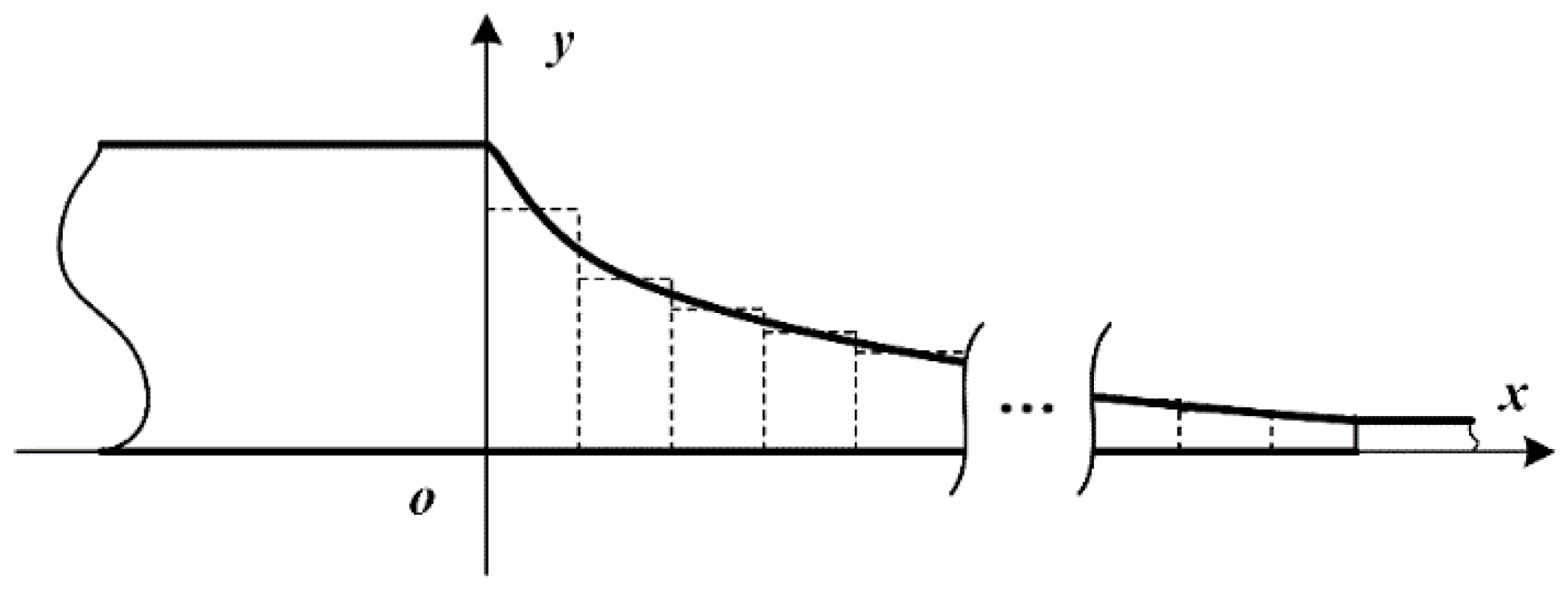
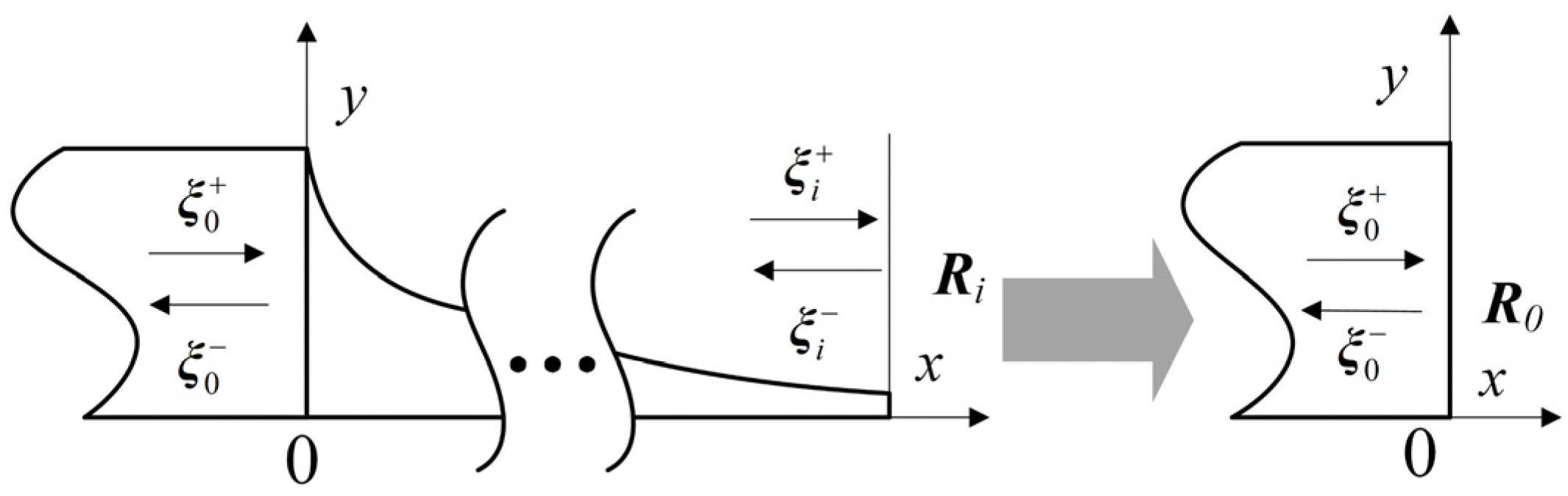
2.3. Analysis Process of the Wave Method
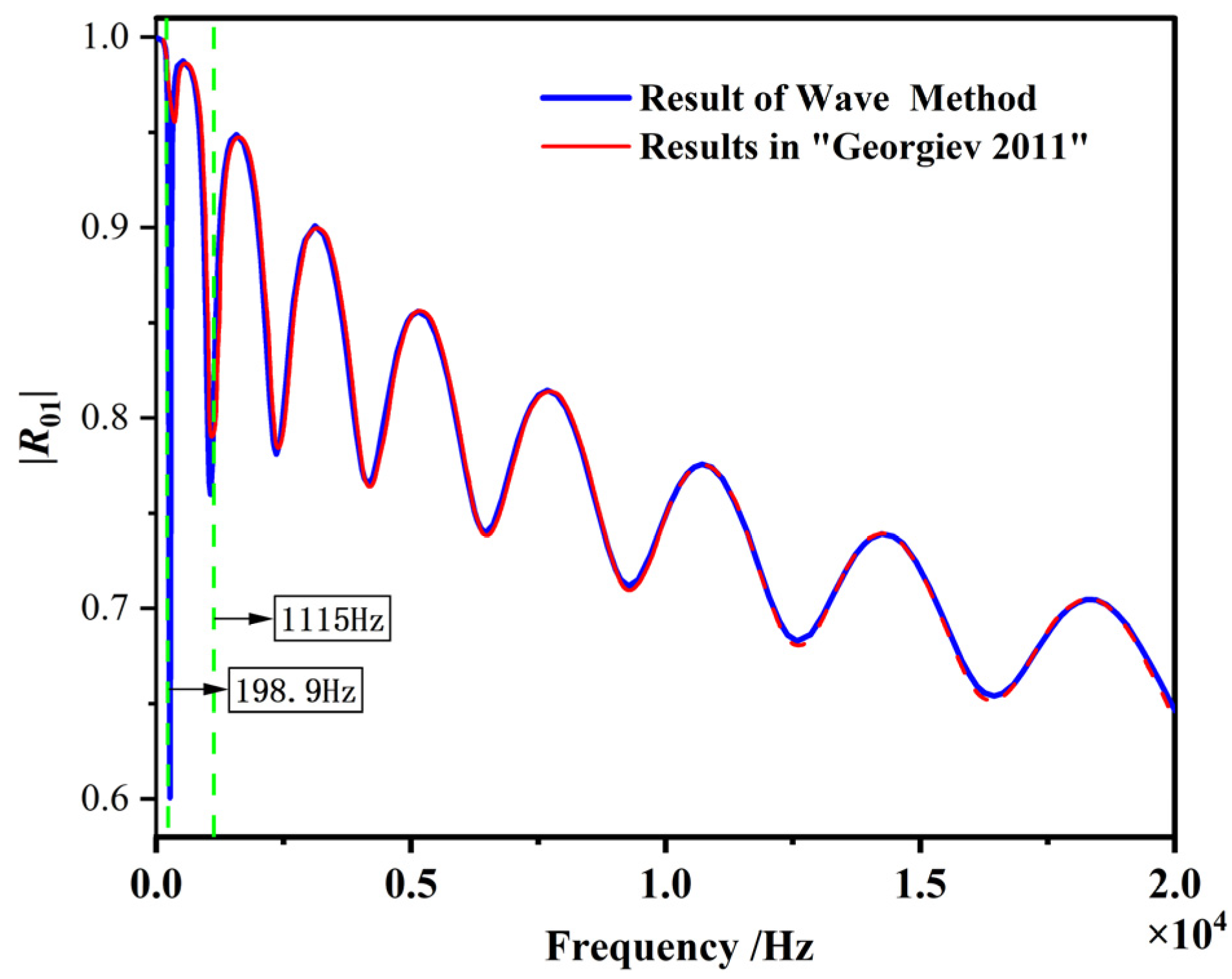
The ABH beam is a special type of non-uniform structure, and its analysis process is extremely complex. Therefore, we extend the wave method [27] to the analysis of non-uniform beam structures, particularly in fractional-order systems. The wave method proves particularly suitable for analyzing vibration problems in this model, as its recursive formulation inherently incorporates continuity conditions for displacement, rotation, shear force, and bending moment during derivation. This characteristic renders it well suited to address the vibration continuity requirements between the two equations governing distinct regions of the structure. The transmission relation for vibrating waves in non-uniform structures is derived in the following part. Suppose that w(x, t) = W(x)et and q(x, t) = F(x)et, the kinetic equation in the form of time-invariant separation is derived:
                                                    E I x 4 W x x 4 ρ ω 2 A x W x = F x   0 x < x 0 E 2 b H h h x + E 1 b H h x + η 1 b H h x i ω α 4 W x x 4 ρ ω 2 A x W x = F x   x 0 x L
As shown in Figure 4, the structure needs to be divided into a sufficient number of uniform beam micro-segments, where the interface of the micro-segments can be considered as a discontinuity feature. Therefore, the wave method is a semi-analytical method and the numerical calculation accuracy can be guaranteed when the number of segments is adequate.
As shown in Figure 5, the W(x) in Equation (12) can be converted into the following form:
W i + 1 x = 1 1 η i + + 1 1 η i     i = 0 , 1 , 2 , , n ,
where n is the number of segments; η i + and η i are the vibration waves in the ith interface.
η i + = a 1 i e i k i x a 2 i e k i x ,   η i = a 3 i e i k i x a 4 i e k i x ,
where aji (j = 1,2,3,4) are the vibrational wave coefficients; ki is the wave number of the ith segment.
k i = ω 2 ρ A i E I i 4     x < x 0 ω 2 ρ A i E 2 b H h h , i + E 1 b H h , i + η 1 b H h , i i ω α 4     x 0 x L ,
The general equivalent iterative computational equations for vibration waves on non-uniform beams can be derived from the vibration wave transfer relationship on beams.
η i + = T i , 1 + ξ 0 + + R i , 1 η i ξ 0 = R i , 1 + ξ 0 + + T i , 1 η i ,
where the iterative formulas for the equivalent transmission and reflection matrices T i , 1 + , T i , 1 , R i , 1 + and R i , 1 in the first i segment are as follows:
T i , 1 + = T i + f i I R i 1 , 1 f i R i + f i 1 T i 1 , 1 + R i , 1 = R i + T i + f i I R i 1 , 1 f i R i + f i 1 R i 1 , 1 f i T i R i , 1 + = R i 1 , 1 + + T i 1 , 1 f i R i + f i I R i 1 , 1 f i R i + f i 1 T i 1 , 1 + T i , 1 = T i 1 , 1 f i T i + T i 1 , 1 f i R i + f i I R i 1 , 1 f i R i + f i 1 R i 1 , 1 f i T i ,
where fi is the transfer matrix between the (i-1)th and ith interfaces, f i = e i k i x 0 0 e k i x ; the transmission and reflection matrices of T i + , T i , R i and R i + of the ith interface are
T i + = 2 Δ i 1 + γ i 1 + β i 1 γ i 1 i β i 1 γ i 1 + i β i 1 + γ i 1 + β i ,   T i = 2 γ i β i Δ i 1 + γ i 1 + β i β i i 1 γ i i + β i 1 γ i 1 + γ i 1 + β i , R i = 1 Δ i i β i γ i 1 2 2 γ i 1 β i 2 1 + i β i 1 γ i 2 1 i β i 1 γ i 2 i β i γ i 1 2 2 γ i 1 β i 2 , R i + = 1 Δ i 2 γ i 1 β i 2 i β i γ i 1 2 1 + i β i 1 γ i 2 1 i β i 1 γ i 2 i β i γ i 1 2 + 2 γ i 1 β i 2 ,
where the coefficients Δi, βi and γi are
Δ i = β i γ i + 1 2 + 2 γ i 1 + β i 2 ,     β i = k i + 1 k i γ i = E 2 I i + 1 k i + 1 2 E 1 I i k i 2     x < x 0 E 2 b H h h , i + 1 + E 1 b H h , i + 1 + η 1 b H h , i + 1 i ω α k i + 1 2 E 2 b H h h , i + E 1 b H h , i + η 1 b H h , i i ω α k i 2     x 0 x L ,
The vibration wave is reflected back from the right end, and the equivalent transmission matrix R0 of the entire ABH structure is obtained when the right end of the ABH structure is not connected to any structure, as shown in Figure 6.
The equivalent reflection matrix R can be obtained by
ξ 0 = R 0 ξ 0 + ,
where R0 is the equivalent reflection matrix.
R 0 = R 0 + + T 0 f 1 R 1 f 1 I R 0 f 1 R 1 f 1 1 T 0 = R 01 R 02 R 03 R 04 ,
where R1 is iteratively calculated using the following equation:
R i k = R i k + + T i k f i k + 1 R i k + 1 f i k + 1 I R i k f i k + 1 R i k + 1 f i k + 1 1 T i k ,     k = 1 , 2 , , i .
According to Reference [27], the fixed boundary matrix R used in this paper is i 1 i 1 + i i , and the free boundary matrix R used is i 1 + i 1 i i .

3. Validation

To validate the effectiveness of the wave method in vibration analysis of ABH structures, the absolute values of the elements |R01| in the reflection matrix R of an overlaying ABH beam with the quadratic curve of the shape function obtained by the wave method are compared with the results in Ref. [31]. The rationale for selecting this study for comparative analysis lies in the fact that the wave-based method is rooted in theoretical mathematical models, which compute the theoretical solution of the reflection matrix R. The simulation parameters are shown in Table 1.
The results in Figure 7 indicate the reflection parameter |R01| as a function of frequency ω, which verifies the ABH effect. The results indicate that the reflection coefficient |R01| of an ABH beam with a 700 μm absorbing film, calculated using the wave method (blue curve) and the method in [31] (red curve), differs by 37.5% in the vicinity of 200 Hz. However, these two curves are close in the mid-to-high frequency range. Therefore, the wave method is effective to investigate the vibration analysis of ABH beams.

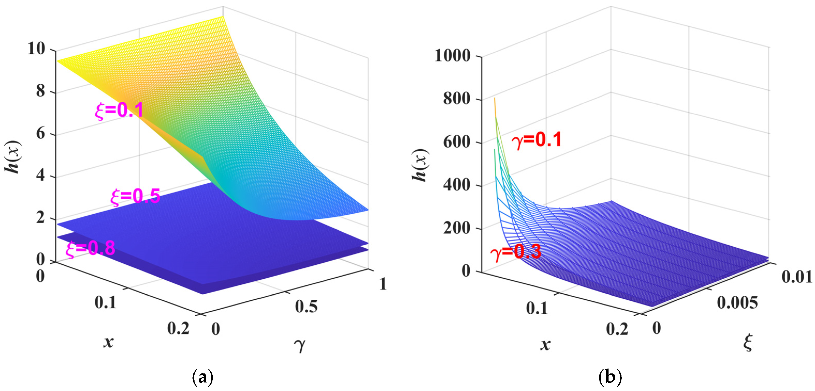
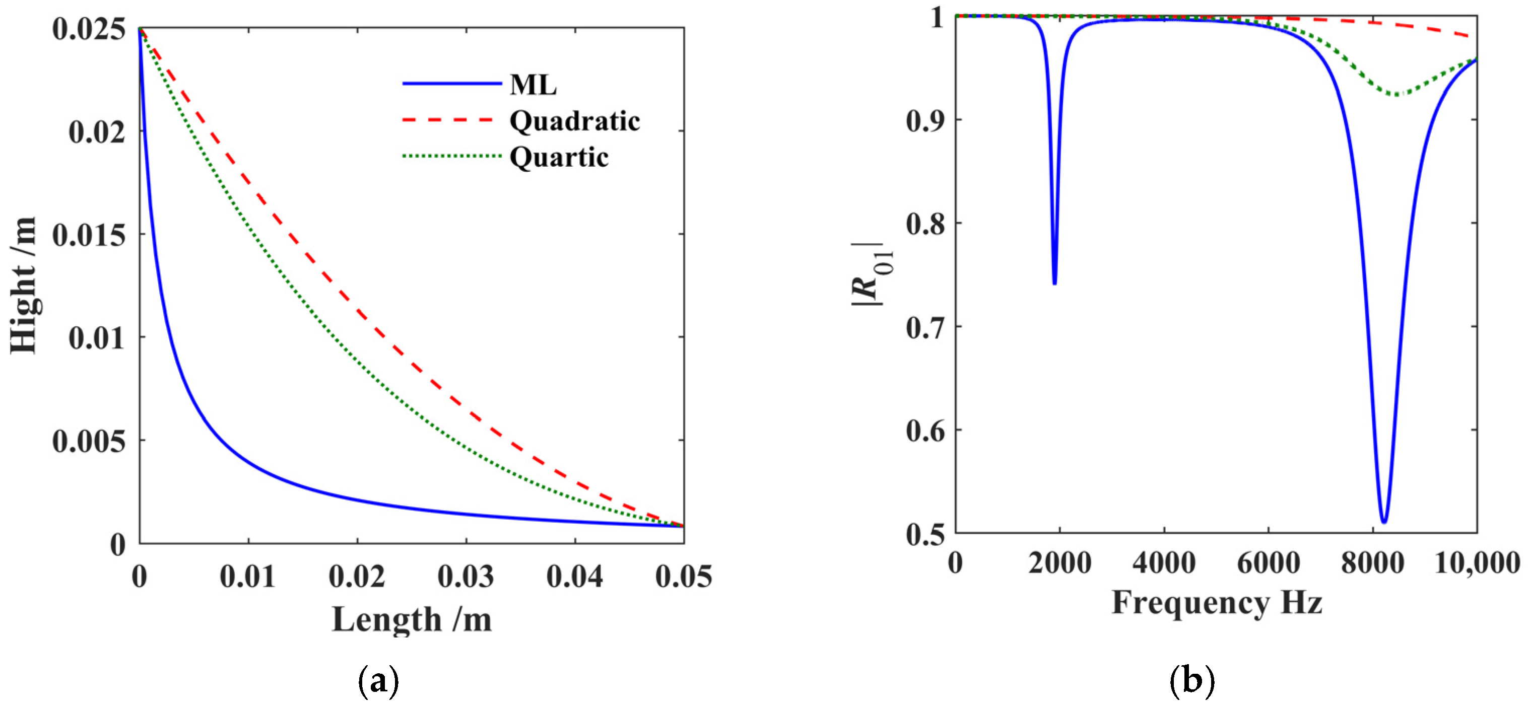
4. New Shape Function of ABH Structures

The ABH structure featuring quadratic and quartic functions has inherent drawbacks, and its energy dissipation and aggregation properties need to be enhanced. Therefore, we introduced a more generalized function, known as the two-parameter ML function, to describe the shape of ABH structure:
E γ , ξ x = k = 0 x k Γ γ k + ξ           h x = a 1 E γ , ξ x
where γ and ξ are the two covariates of the ML function; a is the scaling factor. The ML function can decay quickly first and then slowly reach a stable value, making it easier to truncate. The ML function can be adjusted to simulate other functions such as quadratic and quartic curves by adjusting the parameters, which is a more generalized ABH shape function. By employing a two-parameter ML function, the trend of the curve can be altered through these two characteristic parameters, with the aim of improving the energy dissipation and aggregation performance of the current ABH structure. The influence of the two parameters γ and ξ on the curve results is shown in Figure 8 when the length of the ABH part x = 0.2 m. The parameter γ alters the position of the curve’s endpoint, while the parameter ξ changes the position of the starting point. Figure 8c illustrates the ML-shaped function curves derived from three parameter sets. The results demonstrate that parameter tuning can modulate the variation trend of the curves, enabling them to approximate distinct functions.
Figure 9 illustrates the relationship between h(x) and the ML function parameters of γ and ξ, as well as the length of the ABH part x when a = 1. It can be seen from the results that the smaller the ξ and the larger the γ, the more drastic the change in h(x).
The effects of the two parameters γ and ξ are investigated on the |R01| on the basis of the integer solution model, where α is 1 and the thickness of the cladding film h0 is 0.7 mm. The rationale for setting α = 1 is to eliminate the influence of fractional-order dynamics on the results. Figure 10 illustrates the relationship between |R01| and the ML function parameters of γ and ξ, as well as the external excitation frequency ω. In Figure 10a,b, the external excitation frequency is set to the range [0, 2000] Hz, with parameter γ varying within [0.01, 1] and parameter ξ spanning [0.001, 0.5].
The results in Figure 10a indicate that the surface plot exhibits a large concave area. When γ is fixed, |R01| exhibits a trend of first decreasing and then increasing with the rise in ω. At frequencies below approximately 820 Hz, |R01| decreases as γ decreases. However, at frequencies above 820 Hz, |R01| initially decreases and subsequently increases with decreasing γ. When the frequency exceeds approximately 4150 Hz, |R01| first increases and then decreases as γ decreases. Notably, |R01| reaches its minimum value at ω ≈ 880 Hz and γ ≈ 0.5. The surface results in Figure 10b demonstrate that when ξ is fixed, |R01| first decreases and then increases as ω grows. At frequencies approximately below 750 Hz, |R01| decreases with increasing ξ. For frequencies above approximately 750 Hz but below 3150 Hz, |R01| increases as ξ increases. However, when the frequency exceeds approximately 3150 Hz, |R01| again exhibits a decreasing trend with increasing ξ. The magnitudes of the two ML parameters significantly influence |R01|. As demonstrated in Figure 10c, |R01| attains its minimum value only when ξ is set to a very small value and γ is approximately 0.5. The results demonstrate that optimal parameter selection is essential to achieve superior energy consumption performance.

5. Results Discussion

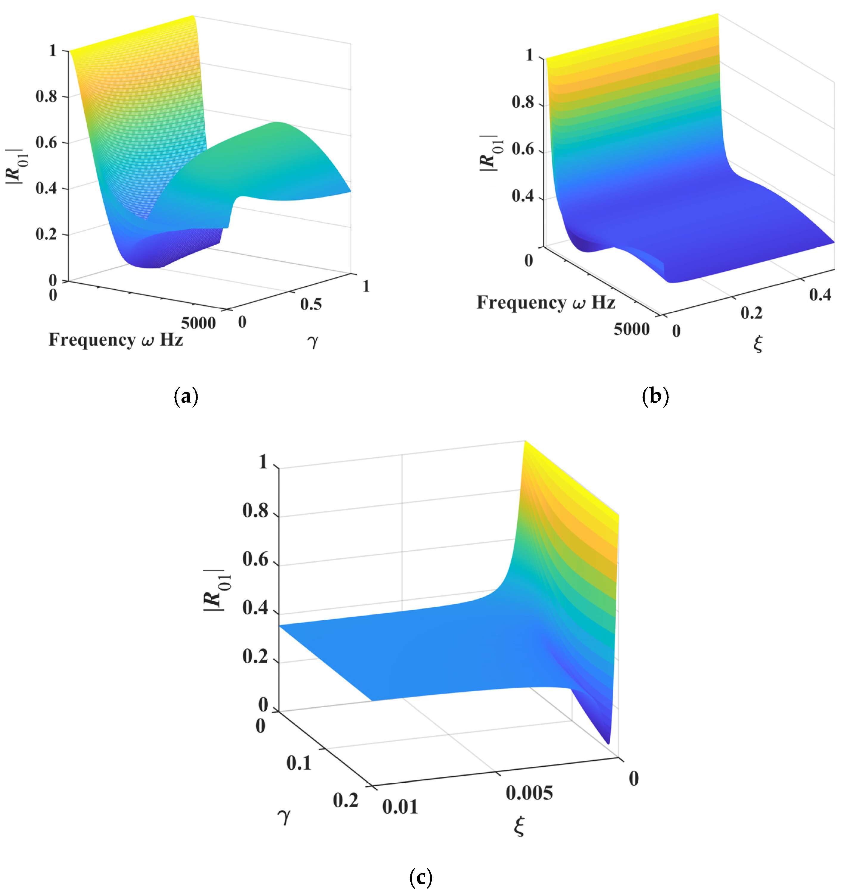
5.1. The Results and Analysis of the Fractional Model of ML-ABH Structure

Previous studies have all been based on analyses conducted using integer-order models. However, the properties of viscoelastic materials are actually closely related to the excitation frequency. To obtain a more accurate understanding of the impact of viscoelastic materials on structural energy transmission characteristics, we have introduced the fractional-order Kelvin model for analysis. The fractional-order parameter α characterizes the viscoelastic properties of the material, with a higher order indicating stronger viscoelastic performance.
Firstly, we present the total reflection parameter |R01| of the fractional-order ABH structure, along with the transmission and reflection matrices T+, T, R+, and R under two sets of parameters. It is noted here that the total reflection parameter |R01| is the parameter of the reflection matrix R generated when no other structure is connected to the right end of the ABH structure. The transmission and reflection matrices T+, T, R+, and R are produced when other structures are connected to the right end of the ABH structure. The parameters selected for the ML shape function are γ = 0.1, ξ = 0.0002, and a = 5 × 10⁻⁶. The rationale for selecting these parameters is to ensure that the ML shape function and the power-law shape functions (quadratic and quartic curves) are distinctly differentiable, such that the three shape function curves yield pronounced differences in the calculated reflection parameter |R01|.
The ABH structure shape function can be obtained from the above parameters, as shown in Figure 11; the blue curve is the ML function, the green curve is a quartic curve, and the red curve is a quadratic curve. When the three ABH-shaped functions are consistent at the beginning and end, compared to quadratic and quartic curves, the ML curve can decay faster and smoothly transition to the final value.
Compared to quadratic and quartic curves, the ML curve exhibits faster decay and a smoother transition to its final value when the three ABH-shaped functions are consistent at both ends. The variation curves of the reflection matrix element |R01| obtained from the three shape functions with respect to frequency ω are shown in Figure 11b when α is 0.5, h0 is 0.7 mm, and x0 is 0. The |R01| curves all exhibit periodic decay, but the values corresponding to the ML shape function are smaller, and they decay faster, which is more beneficial for structural vibration reduction.
In addition, the relationship curve between |R01| and ω under different film thicknesses and different fractional orders was studied, as shown in Figure 12. Since the truncation thickness is 8.2554 × 10⁻⁴ mm, we select two film covering thicknesses h0 of 0.01 mm and 0.7 mm, which are, respectively, smaller and larger than the truncation thickness, as the research parameters. The results show that the fractional order of the model and the thickness of the membrane have significant effects on the structural vibration reduction. The greater the α, the greater the attenuation of |R01|, which also means that the vibration energy is continuously dissipated in the reflection process. This is consistent with the actual implementation. The fractional order reflects the dissipation performance of the coated material. The greater the α, the stronger the dissipation performance of the material, that is, the stronger the damping performance. From the overall results, the greater the film thickness h0, the stronger the damping performance of the material, and the greater the attenuation degree of |R01|. However, in Figure 12b, the dissipation results of α = 0.6 in the high-frequency range are more significant than those of α = 0.8 when h0 is 0.7 mm. This is because the right end of the ABH structure is truncated, and its thickness is 8.2554 × 10⁻⁴ mm, which is equivalent to the film thickness of 0.7 mm, and there is a scale effect.
The research results on the energy transfer characteristics of the ABH section with an infinitely long structure connected to the right side are shown in Figure 13 and Figure 14, where T+ represents the forward energy transmission and R+ represents the forward energy reflection. When the film thickness h0 is 0.01 mm, only the result of α = 0.8 is more significant, and the difference in the results of other fractional orders is small, indicating that the difference in the viscoelastic properties of the material is small. When the film thickness h0 is 0.7 mm, there is a significant difference in the results at different fractional orders, indicating a large difference in the viscoelastic properties of the material, especially when the order is high. From the numerical values in the figure, it can be seen that the higher the fractional order, the smaller the forward energy transmission and the smaller the forward energy reflection. Furthermore, based on the values of |R01| and R+ matrix elements, it can be inferred that no matter how materials are selected or structures are designed, ABH structures cannot dissipate all energy and there must be energy reflection. According to the values of the elements of matrix T+, we can connect a damping device on the right side of the ABH for secondary energy dissipation, further reducing vibration energy.

5.2. Analysis of PSO Algorithm Optimization Results

Based on the above two results, it can be observed that the three parameters of the ML shape function have a significant impact on the vibration reduction performance of the structure. Therefore, we introduce the PSO algorithm to optimize these parameters in order to achieve optimal vibration reduction performance. The influence of film coating thickness, coating length, and fractional-order parameter on optimization outcomes is investigated. The objective of this study is to analyze the influence of two coating thicknesses (one greater than and the other less than the ABH truncation thickness) on the minimum reflection element |R01|. In addition, the study investigates the effects of three coating lengths (long, medium, and short) and fractional derivative orders (large and small) on the minimum reflection element |R01|. Therefore, we have investigated the optimal ML parameters and fitness functions under different coating thicknesses (h0 = 0.01 mm and 0.7 mm), lengths (0.2 L, 0.5 L, and 0.8 L), and fractional orders (α = 0.2 and 0.8), respectively.
The PSO algorithm parameters are as follows: the population size is 300, the number of iterations is 30, the parameter variation range is [0.00001, 1], and the objective function is f = min(|R01(ω)|). In this case, the right end of the ABH structure is not connected to any structure. The optimization results of the PSO algorithm are shown in Table 2.
According to the results in Table 2, it can be concluded that the optimized |R01| minimum value is the smallest when the coating length is 0.8 L, indicating that the longer the coating, the more significant its energy dissipation performance. Under the same film thickness and fractional order, the optimized parameters obtained are similar, with the coefficient a exhibiting a more significant difference when h0 is 0.01 mm. This is mainly due to the long reciprocating motion of the vibration wave in the viscoelastic material layer, which dissipates a large amount of energy. The parameters can achieve the minimum value min = 0.0086 when h0 is 0.01 mm, α is 0.8, and x0 is 0.2 L, at which point the energy inside the structure is basically dissipated. There is a special case in the table where h0 is 0.7 mm and α is 0.8, where the minimum value of |R01| is large and the energy dissipation result is poor. This may be due to the PSO algorithm becoming stuck in a local optimal solution. Under such parameters, the structural dissipation performance is weak, which is not conducive to structural vibration reduction. With these optimized parameters, the structural dissipation efficiency turns out to be insufficient, impeding effective vibration reduction. This distinction highlights one of the key differences between fractional-order and integer-order models. In subsequent research, we can use other optimization algorithms or PSO improvement algorithms to obtain more accurate optimal ML shape function parameters in order to achieve good structural energy dissipation performance.
Based on the results in Table 2, we selected the aforementioned optimal parameters to determine the ABH shape function and analyzed the influence of fractional order, film thickness, and length on the structural vibration reduction performance under these parameters.
The impact of fractional order, film thickness, and film length on the reflection matrix element |R01| is shown in the 3D graph in Figure 15. It can be seen that the surfaces in the three figures all exhibit periodic fluctuations with frequency changes. In Figure 15a, the range of fractional-order values within the range of [0.6, 1] will cause significant fluctuations in |R01|. When the order α is 0.8, |R01| is at its minimum and the frequency is around 8000 Hz.
The range of h0 values in Figure 15b is [10−5, 10−3], and there is a significant change in |R01| within the frequency range of [7500 Hz, 8000 Hz] and h0 ≤ 0.0003 mm. |R01| has the smallest value when h0 is 0.0001 mm. The range of x0 values in Figure 15c is [0.001, 0.049]. When x0 falls within the range of [0.001, 0.014] and frequency is within the range of [5300 Hz, 9691 Hz], |R01| can achieve multiple small values, with the minimum value occurring at x0 = 0.2 L. The result is consistent with the optimization results.

6. Conclusions

In this paper, a more generalized ABH shape function is proposed, which is employed to improve the energy dissipation characteristics of ABH structures incorporating viscoelastic layers. Compared with traditional power-law shape functions, the ML shape function represents a more generalized function whose parameters can be adjusted to enhance the energy dissipation characteristics of ABH structures. Since fractional-order constitutive models can more accurately capture the properties of viscoelastic materials, a fractional-order viscoelastic ABH structure vibration model was established, which was close to the real vibration results. The current literature on the development of fractional-order models for ABH structures predominantly focuses on fractional-order boundary conditions and acoustic fields. In contrast, the fractional-order ABH beam model proposed in this work is established from the perspectives of constitutive models and the mechanical behavior of composite structures, resulting in an inhomogeneous beam formulation. To investigate the energy transmission and reflection characteristics of ML-ABH structures under steady-state conditions, the wave method is introduced. Furthermore, we have extended the theoretical framework of the wave method for analyzing inhomogeneous beam structures. The parameters of the proposed shape function exhibit a pronounced influence on the reflection coefficient (|R01|) of the ABH structure. To achieve optimal vibration reduction performance of the ABH structures, the PSO algorithm is introduced to optimize these parameters.
The effectiveness of the wave method was verified by comparing it with |R01| in the literature [31]. Research on new shape functions and fractional-order models shows that the thickness and length of the coating, as well as the fractional order of the model, have a significant impact on the energy transmission and reflection characteristics of ML-ABH structures. By optimizing algorithms and selecting ML shape function parameters reasonably, the optimal vibration reduction performance can be achieved. Overall, the higher the fractional order, the stronger the damping characteristics of the structure, thereby enhancing its ability to attenuate vibrations. The thicker the coating of the ABH beam, the higher the external excitation frequency, and the stronger the ability to attenuate vibration. In addition, the longer the length of the film, the more significant the suppression of ABH structure vibration. However, when the thickness of the film is large, scale effects may occur, which may lead to a decrease in vibration damping performance. Parameter selection is not universally governed by maximization or minimization; instead, it requires balanced optimization to achieve optimal performance in ABH structures. Therefore, according to different ABH structural vibration models, it is necessary to choose the appropriate coating length and thickness in order to obtain the best vibration reduction performance. It is worth noting that regardless of the material selection or structural design, ABH structures cannot dissipate all energy and must have some energy reflection. Therefore, we can connect a damping device on the right side of an ABH for secondary energy dissipation, thereby further reducing vibration energy.
This article provides a theoretical basis for vibration reduction, energy recovery, and design research of ABH sensors within ABH structures. In subsequent research, we will investigate the impact of ML functions with multiple parameters, such as three-parameter and four-parameter ML functions, on energy transfer and aggregation effects.

Author Contributions

Conceptualization, J.X.; methodology, J.X. and N.C.; software, J.X.; validation, J.X. and N.C.; writing—original draft preparation, J.X.; writing—review and editing, J.X. and N.C.; funding acquisition, J.X. All authors have read and agreed to the published version of the manuscript.

Funding

This research was funded by the Natural Science Research Project of Anhui Educational Committee, grant numbers 2023AH051432 and 2022AH052064, and the Research and Innovation Team of Anhui Vocational and Technical College, grant numbers 2022xjkytd2 and 2022xjkytd3.

Institutional Review Board Statement

Not applicable.

Informed Consent Statement

Not applicable.

Data Availability Statement

The original contributions presented in this study are included in the article. Further inquiries can be directed to the corresponding authors.

Conflicts of Interest

The authors declare no conflicts of interest.

References

  1. Mironov, M.A. Propagation of a flexural wave in a plate whose thickness decreases smoothly to zero in a finite interval. Sov. Phys. Acoust. USSR 1988, 34, 318–319. [Google Scholar]
  2. Krylov, V.V. New type of vibration dampers utilising the effect of acoustic ‘black holes’. Acta Acust. United Acust. 2004, 90, 830–837. [Google Scholar]
  3. Li, X.; Ding, Q. Sound radiation of a beam with a wedge-shaped edge embedding acoustic black hole feature. J. Sound Vib. 2019, 439, 287–299. [Google Scholar] [CrossRef]
  4. Huang, W.; Zhang, H.; Inman, D.J.; Qiu, J.; Cesnik, C.E.; Ji, H. Low reflection effect by 3D printed functionally graded acoustic black holes. J. Sound Vib. 2019, 450, 96–108. [Google Scholar] [CrossRef]
  5. Li, X.; Ding, Q. Analysis on vibration energy concentration of the one-dimensional wedge-shaped acoustic black hole structure. J. Intell. Mater. Syst. Struct. 2018, 29, 2137–2148. [Google Scholar] [CrossRef]
  6. Ji, H.; Liang, Y.; Qiu, J.; Cheng, L.; Wu, Y. Enhancement of vibration based energy harvesting using compound acoustic black holes. Mech. Syst. Signal Process. 2019, 132, 441–456. [Google Scholar] [CrossRef]
  7. Deng, J.; Guasch, O.; Zheng, L.; Song, T.; Cao, Y. Semi-analytical model of an acoustic black hole piezoelectric bimorph cantilever for energy harvesting. J. Sound Vib. 2021, 494, 115790. [Google Scholar] [CrossRef]
  8. Zhang, L.; Kerschen, G.; Cheng, L. Electromechanical coupling and energy conversion in a PZT-coated acoustic black hole beam. Int. J. Appl. Mech. 2020, 12, 2050095. [Google Scholar] [CrossRef]
  9. Li, H.; Doaré, O.; Touzé, C.; Pelat, A.; Gautier, F. Energy harvesting efficiency of unimorph piezoelectric acoustic black hole cantilever shunted by resistive and inductive circuits. Int. J. Solids Struct. 2022, 238, 111409. [Google Scholar] [CrossRef]
  10. Park, S.; Jeon, W. Concave-shaped acoustic black holes with asymmetric arrangement for suppression and amplification of structural vibration. J. Sound Vib. 2025, 600, 118885. [Google Scholar] [CrossRef]
  11. Yang, M.; Chen, C.; Wei, L.; Chen, X.; Sun, X.; Fu, H. Semi-analytical model and vibrational energy recovery efficiency of piezoelectric beams with quasi-periodic additional acoustic black holes. Appl. Phys. A 2024, 130, 928. [Google Scholar] [CrossRef]
  12. Wang, Y.; Du, J.; Cheng, L. Power flow and structural intensity analyses of acoustic black hole beams. Mech. Syst. Signal Process. 2019, 131, 538–553. [Google Scholar] [CrossRef]
  13. Deng, J.; Zheng, L.; Zeng, P.; Zuo, Y.; Guasch, O. Passive constrained viscoelastic layers to improve the efficiency of truncated acoustic black holes in beams. Mech. Syst. Signal Process. 2019, 118, 461–476. [Google Scholar] [CrossRef]
  14. McCormick, C.A.; Shepherd, M.R. Optimization of an acoustic black hole vibration absorber at the end of a cantilever beam. J. Acoust. Soc. Am. 2019, 145, EL593–EL597. [Google Scholar] [CrossRef]
  15. Deng, J.; Guasch, O.; Zheng, L. A semi-analytical method for characterizing vibrations in circular beams with embedded acoustic black holes. J. Sound Vib. 2020, 476, 115307. [Google Scholar] [CrossRef]
  16. Cao, S.; Lee, H.P.; Lim, K.M. Estimation of Wave Reflection Coefficient by Semi-Analytical Method in an Acoustic Black Hole Beam. Int. J. Appl. Mech. 2020, 12, 2050004. [Google Scholar] [CrossRef]
  17. He, M.-X.; Ding, Q. Data-driven optimization of the periodic beam with multiple acoustic black holes. J. Sound Vib. 2021, 493, 115816. [Google Scholar] [CrossRef]
  18. Li, P.; Biwa, S. Flexural waves in a periodic non-uniform Euler-Bernoulli beam: Analysis for arbitrary contour profiles and applications to wave control. Int. J. Mech. Sci. 2020, 188, 105948. [Google Scholar] [CrossRef]
  19. Li, W.; Wen, H.; Guo, J. A multiscale Gaussian expansion method for low-frequency multimodal damping analysis of variable stiffness acoustic black hole beams. Thin-Walled Struct. 2025, 206, 112619. [Google Scholar] [CrossRef]
  20. Gao, N.; Wei, Z.; Hou, H.; Krushynska, A.O. Design and experimental investigation of V-folded beams with acoustic black hole indentations. J. Acoust. Soc. Am. 2019, 145, EL79–EL83. [Google Scholar] [CrossRef]
  21. Li, H.; Touzé, C.; Pelat, A.; Gautier, F. Combining nonlinear vibration absorbers and the Acoustic Black Hole for passive broadband flexural vibration mitigation. Int. J. Non-Linear Mech. 2021, 129, 103558. [Google Scholar] [CrossRef]
  22. Zhang, Y.; Chen, K.; Zhou, S.; Wei, Z. An ultralight phononic beam with a broad low-frequency band gap using the complex lattice of acoustic black holes. Appl. Phys. Express 2019, 12, 077002. [Google Scholar] [CrossRef]
  23. Gao, N.; Wei, Z.; Zhang, R.; Hou, H. Low-frequency elastic wave attenuation in a composite acoustic black hole beam. Appl. Acoust. 2019, 154, 68–76. [Google Scholar] [CrossRef]
  24. Zhang, Y.; Chen, K.; Cheng, Y.; Wei, Z. Lightweight-high-stiffness vibration insulator with ultra-broad band using graded double-leaf acoustic black holes. Appl. Phys. Express 2020, 13, 17007. [Google Scholar] [CrossRef]
  25. Park, S.; Kim, M.; Jeon, W. Experimental validation of vibration damping using an Archimedean spiral acoustic black hole. J. Sound Vib. 2019, 459, 114838. [Google Scholar] [CrossRef]
  26. Kim, S.-Y.; Lee, D. Numerical simulation of characteristics of wave propagation and reflection coefficient in a helix-acoustic black hole. J. Vib. Control 2020, 28, 615–625. [Google Scholar] [CrossRef]
  27. Xu, J.; Chen, Y.; Tai, Y.; Xu, X.; Shi, G.; Chen, N. Vibration analysis of complex fractional viscoelastic beam structures by the wave method. Int. J. Mech. Sci. 2020, 167, 105204. [Google Scholar] [CrossRef]
  28. Xu, J.; Chen, Y.; Tai, Y.; Shi, G.; Chen, N. Vibration analysis of sandwich beams with viscoelastic coating described by fractional constitutive equation. Mech. Adv. Mater. Struct. 2022, 29, 429–439. [Google Scholar] [CrossRef]
  29. Oskouie, M.F.; Ansari, R. Linear and nonlinear vibrations of fractional viscoelastic Timoshenko nanobeams considering surface energy effects. Appl. Math. Model. 2017, 43, 337–350. [Google Scholar] [CrossRef]
  30. Hollkamp, J.P.; Semperlotti, F. Application of fractional order operators to the simulation of ducts with acoustic black hole terminations. J. Sound Vib. 2020, 465, 115035. [Google Scholar] [CrossRef]
  31. Georgiev, V.; Cuenca, J.; Gautier, F.; Simon, L.; Krylov, V.V. Damping of structural vibrations in beams and elliptical plates using the acoustic black hole effect. J. Sound Vib. 2011, 330, 2497–2508. [Google Scholar] [CrossRef]
Figure 1. The ABH structure.
Applsci 15 02768 g001
Figure 2. Viscoelastic ABH beam with fixed-thickness film coverage.
Applsci 15 02768 g002
Figure 3. Deformation form of a micro-fracture of the film-covered beams.
Applsci 15 02768 g003
Figure 4. Analysis technological process of ABH structure.
Applsci 15 02768 g004
Figure 5. Distribution of vibration waves of the discontinuous beam.
Applsci 15 02768 g005
Figure 6. Equivalent diagram of ABH structure.
Applsci 15 02768 g006
Figure 7. The reflection matrix parameter |R01| of the ABH beam with 0.7 mm coated layer obtained by the wave method and the approach from literature [31], with two significant discrepancies in the comparative results indicated by green dashed lines.
Applsci 15 02768 g007
Figure 8. The variation curve of ML functions with respect to parameters: (a) γ = 0.2, 0.4, 0.6 and 0.8 with ξ = 0.005; (b) ξ = 0.002, 0.004, 0.006 and 0.008 with γ = 0.1; (c) ML-shaped function tuning chart.
Applsci 15 02768 g008
Figure 9. (a) The surface of h(x) changing with x and γ with ξ = 0.1, 0.5 and 0.8. (b) The surface of h(x) changing with x and γ with ξ = 0.1, 0.5 and 0.8.
Applsci 15 02768 g009
Figure 10. (a) The 3D surface of |R01| with respect to ω and γ when ξ is 0.0005 and h0 is 0.07 mm; (b) the 3D surface of |R01| with respect to ω and ξ when γ is 0.1 and h0 is 0.07 mm; (c) the 3D surface of |R01| with respect to ω and γ when ω is 1000 Hz and h0 is 0.07 mm.
Applsci 15 02768 g010
Figure 11. (a) Comparison of three kinds of ABH shape function curves; (b) reflection matrix parameter |R01| of ABH beam.
Applsci 15 02768 g011
Figure 12. The relationship curves between the reflection coefficient |R01| of the ABH beam and frequency under different fractional-order values for (a) a 0.01 mm absorber film; (b) a 0.7 mm absorber film.
Applsci 15 02768 g012
Figure 13. Comparison of transmission and reflection matrices under the value of fractional order α of 0.2, 0.4, 0.6 and 0.8 when the h0 is 0.01 mm: (a) the elements of matrix T+; (b) the elements of matrix R+.
Applsci 15 02768 g013
Figure 14. Comparison of transmission and reflection matrices under the value of fractional order α of 0.2, 0.4, 0.6 and 0.8 when the h0 is 0.7 mm: (a) the elements of matrix T+; (b) the elements of matrix R+.
Applsci 15 02768 g014
Figure 15. (a) A 3D surface plot of |R01| with respect to frequency ω and fractional order α when γ = 0.5694; ξ = 0.4231; a = 0.0012 and h0 = 0.01 mm.; (b) a 3D surface plot of |R01| with respect to frequency ω and the film thickness h0 when γ = 0.5694; ξ = 0.4231; a = 0.0012 and α = 0.8; (c) a 3D surface plot of |R01| with respect to frequency ω and the film length L-x0 when γ = 0.5694; ξ = 0.4231; a = 0.0012; α = 0.8 and h0 = 0.01 mm.
Applsci 15 02768 g015
Table 1. Structural and material parameters of the ABH beam.
Geometrical CharacteristicsCharacteristics of Material
L = 0.05 m
h = 0.0015 m
Beam
E1 = 210 Gpa
ρ 1   =   7800   kg / m 3
η 1   =   0.001
b = 0.0015 m
m = 4
Absorbing film
E2 = 0.5 Gpa
ρ 2   =   950   kg / m 3
η 2   =   0.05
Table 2. The shape parameters and fitness values obtained through the PSO algorithm optimization.
Thickness of FilmαLength of FilmML ParametersFitness Value
h0 ξγa
0.01 mm0.20.8 L0.58860.64682.7745 × 10−50.4845
0.5 L0.65560.68301.1889 × 10−40.9638
0.2 L0.65620.68277.7302 × 10−60.11
0.80.8 L0.56940.42310.00120.0086
0.5 L0.65120.43696.2344 × 10−40.4313
0.2 L0.65290.41845.2108 × 10−50.9066
0.7 mm0.20.8 L0.77650.46250.00030.0605
0.5 L0.77650.46250.00030.0640
0.2 L0.74620.39270.00010.9494
0.80.8 L0.85640.40140.00120.9752
0.5 L0.87590.36780.00060.9944
0.2 L0.86580.40340.00090.999
Disclaimer/Publisher’s Note: The statements, opinions and data contained in all publications are solely those of the individual author(s) and contributor(s) and not of MDPI and/or the editor(s). MDPI and/or the editor(s) disclaim responsibility for any injury to people or property resulting from any ideas, methods, instructions or products referred to in the content.

