Article

High-Precision Compensation Method for Image Plane Deformation in the Doubly Telecentric Projection Optical System

by
Yuwei Xu
1,2,3,4,
Hongbo Wu
1,2,3,4,*,
Guangwei Shi
1,2,3,4,*,
Haokun Ye
1,2,3,4,
Jipeng Zhang
1,2,3,4 and
Yuqi Huang
1,2,3,4
1
Changchun Institute of Optics, Fine Mechanics and Physics, Chinese Academy of Sciences, Changchun 130033, China
2
University of Chinese Academy of Sciences, Beijing 100049, China
3
State Key Laboratory of Applied Optics, Changchun 130033, China
4
Key Laboratory of Optical System Advanced Manufacturing Technology, Chinese Academy of Sciences, Changchun 130033, China
*
Authors to whom correspondence should be addressed.
Appl. Sci. 2025, 15(5), 2691; https://doi.org/10.3390/app15052691
Submission received: 3 January 2025 / Revised: 12 February 2025 / Accepted: 12 February 2025 / Published: 3 March 2025

Abstract

:
The deformation of the image plane due to gravity, clamping forces, and surface shape errors can significantly impact the exposure accuracy and imaging quality of the doubly telecentric projection optical system. To address the issues of resolution and image quality degradation resulting from non-conjugate image planes, this paper proposes a high-precision method for compensating image plane deformation using a dual-prism approach, establishes an analytical compensation model, and the theoretical derivation and quantification of the effects of compensation devices on image plane defocus, tilt, and aberration are provided. Compared to traditional simulation methods, the proposed approach offers a more predictable and precise compensation framework. The optimized design of the dual-prism compensation device has been validated through simulations, demonstrating the ability to control image plane deformation within 3.011 µm, which is smaller than the system’s depth of focus. The results indicate that this method significantly enhances the imaging accuracy of doubly telecentric projection optical systems and presents a novel theoretical tool for optimizing the design of optical compensation devices, thereby advancing the development of high-precision optical compensation technologies.

1. Introduction

The rapid advancements in high-end equipment fields, such as semiconductor manufacturing [1,2], flat-panel display exposure, and wafer defect inspection, have placed increasing demands on the imaging accuracy and compensation capabilities of doubly telecentric projection optical systems [3,4,5,6,7,8]. In systems that utilize large-size masks as object planes and large-size glass substrates as image planes, the structural characteristics of these components make them susceptible to deformation caused by gravity and clamping forces during scanning exposure. Figure 1 is a schematic diagram of image plane deformation. This deformation results in positional shifts and distortions in the projected patterns on the substrate, which significantly impacts the performance of the system [9,10]. Therefore, effective compensation for deformations in both the object and image planes is essential for improving exposure accuracy.
Previous studies have explored both mechanical and optical compensation methods to mitigate image plane deformation [11,12,13,14]. Mechanical compensation involves adjusting the position of objects and image planes to restore conjugation and is widely used due to its simplicity and the absence of additional optical components [15]. However, this method can only provide average adjustments and lacks the precision required for high-end optical systems. In contrast, optical compensation introduces compensating elements (such as phase plates, adaptive optics elements, or prisms) into the optical path to dynamically correct image distortions [16]. Despite offering higher accuracy, existing optical compensation methods heavily rely on empirical fitting and numerical simulation rather than analytical models, limiting their predictability and effectiveness [17].
Several researchers have investigated the use of prisms and phase compensation techniques in aberration correction and image stabilization. Sasian et al. analyzed the influence of a single wedge prism on optical aberrations [18,19], while Moore et al. developed aberration analysis and correction strategies for combinations of planar symmetric optical systems [20]. However, most prior work has focused on aberration correction in general optical systems rather than high-precision doubly telecentric projection optical systems, where large-scale image plane deformations present additional challenges. Moreover, existing optical compensation methods cannot fully quantify the relationship between prism adjustments and the resulting image plane deformation, leading to uncertainty in compensation accuracy.
To address these challenges, this study proposes a novel high-precision dual-prism compensation method based on aberration theory, specifically designed to mitigate image plane deformation in doubly telecentric projection optical systems. Unlike previous approaches that rely on simulation-based fitting methods, this study establishes a comprehensive analytical compensation model, quantifies defocus, tilt, and aberration effects, and derives precise relationships between prism parameters and image corrections. The proposed method is validated through simulations, demonstrating significant improvements in image quality and providing theoretical support for future doubly telecentric projection optical system designs. This approach offers a more systematic, predictable, and analytically driven solution for high-precision image plane compensation, marking a substantial advancement over existing methods.

2. Construction of the Defocus and Tilt Compensation Theoretical Model

The optical behavior of a wedge prism resembles that of a thick parallel plate [21]. As the optical path length varies across different positions within the prism, this characteristic can be leveraged to adjust or correct the tilt of the image plane. Although placing a wedge prism near the image plane may introduce some degree of aberration, these effects can be effectively managed during the design phase, making the wedge prism a reliable tool for adjusting the imaging position of optical systems.
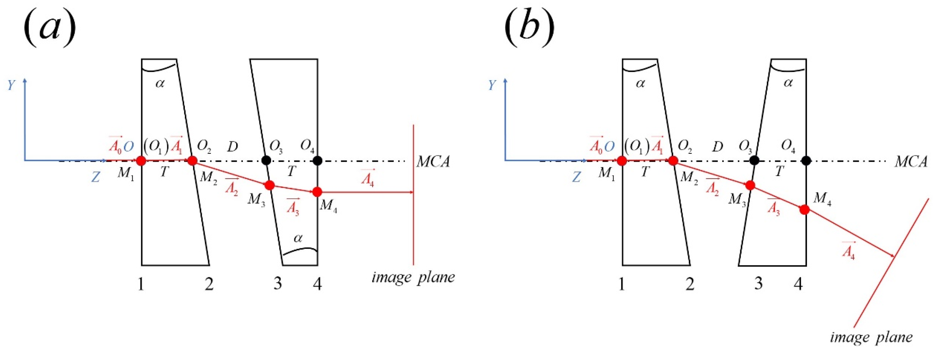
In imaging adjustments, a transmissive first wedge prism and a second wedge prism are employed, both mounted on a mechanical axis (MCA). The first wedge prism remains stationary, while the second wedge prism is adjusted through axial movement, oblique movement, and relative rotation around the MCA. This configuration allows for precise control over the imaging position, effectively reducing defocus errors and compensating for image plane tilt.
During the exposure process, when the mask stage supporting the mask and the substrate stage supporting the glass substrate move synchronously, the use of wedge prisms significantly reduces positional errors between the ideal and actual image planes. This ensures accuracy and consistency throughout the exposure process. Figure 2 illustrates the schematic of the image plane deformation compensation model and its adjustment mechanisms.

2.1. Dual-Prism Compensation Theoretical Model

A Cartesian coordinate system, OXYZ, is established as shown in Figure 3, with its origin O positioned at the center of the first prism’s flat surface. The Z-axis aligns with the mechanical axis (MCA). The two wedge prisms, prism 1 and prism 2, share an identical wedge angle α and have respective thicknesses denoted as t 1 and t 2 . Prism 1 is fixed on the MCA, while prism 2 allows for oblique movement, axial displacement, and independent rotation. The rotation angle is defined as ω .
The direction of the optical axis is accurately determined using Snell’s law:
A i = n i 1 n i A i 1 1 n i 1 n i 2 1 A i 1 T N i 2 n i 1 n i A i 1 T N i N i , i = 1 , 2 , 3 , 4
where n i 1 and n i represent the refractive indices of the object and image sides, respectively. A i 1 and A i denote the direction cosines of the incident and refracted light rays, while N i refers to the direction cosine of the surface normal.
Coddington’s equations play a crucial role in the study of astigmatism by mathematically relating the vertex of a surface to the distances of the astigmatic lines. In this study, these equations are used to determine the position of the sagittal image plane, as expressed below:
n S n S = n cos ( I ) n cos ( I ) R
S i = S i 1 Δ S i
Since the curvature of the plane is zero, the equation simplifies to:
R , n i S i = n i S i
By decomposing the wedge prism into a parallel plate and a wedge, the effects of system parameters on image plane adjustments can be more clearly understood. The wedge facilitates tilt adjustments of the image plane (rotation), calculated using Snell’s law, while the parallel plate handles positional adjustments (translation), as expressed by the following equation:
( Δ x , Δ y , Δ z ) T = 0 , 0 , 1 N n 2 + N 2 1 t T
where t represents the thickness of the plate.
The adjustment of the image plane by the dual-prism is expressed as follows:
Δ x total Δ y total Δ z total = L 4 S 3 M 2 Δ S + M 4 S 3 N 2 Δ S + N 4 S 3 + 1 N n 2 + N 2 1 T + Δ T
This method, by decomposing the wedge prism, provides a deeper understanding of its functionality. The prism moves along its inclined surface, adjusting the optical path by varying its thickness Δ T within the optical path, thereby achieving axial movement of the image plane. Furthermore, since the air gap between the prisms remains constant during oblique movement, this adjustment does not introduce lateral displacement of the image plane. The lateral displacement is determined by the object distance S , while the orientation of the image plane is defined by the prism’s rotation angle.
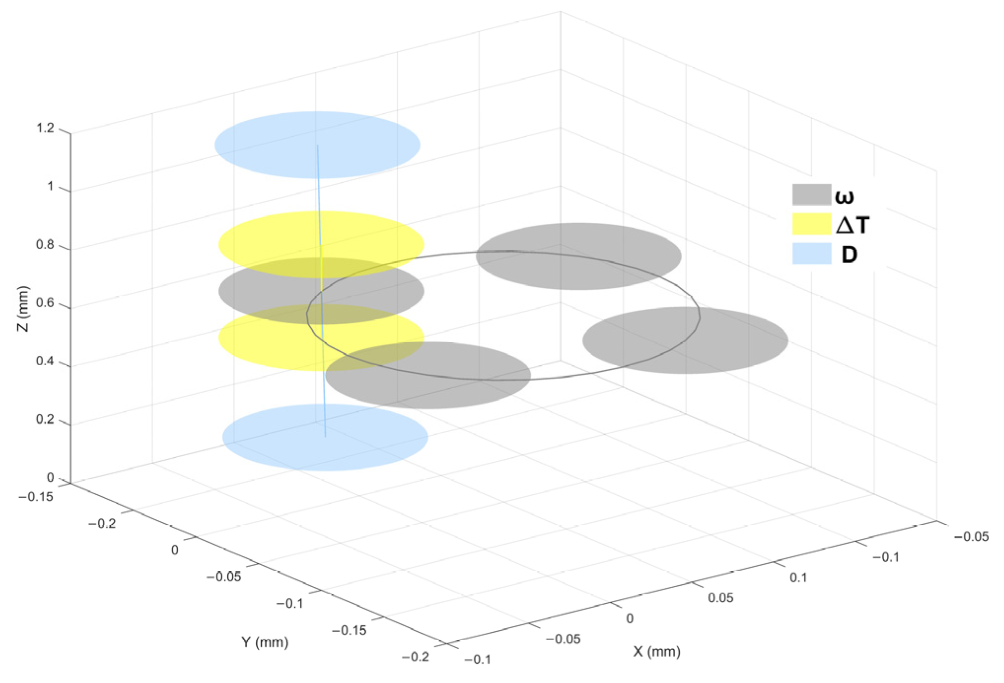
To visually illustrate the effects of different parameters on the image plane, a schematic diagram is provided (see Figure 4). In the diagram, the gray image plane represents the changes caused by the rotation angle ω and the black line indicates the position changes of the image plane after one rotation of the wedge-shaped prism. Four feature positions are selected and displayed in the figure. Similarly, the blue image plane represents positional changes due to variations in parameter D , which corresponds to the positional change of the image plane caused by altering the spacing between two wedge prisms; the yellow image plane corresponds to changes from parameter Δ T , which is the change in image plane position caused by the oblique motion of the second prism. This is abstracted as a mathematical model, specifically the change in image plane position resulting from the change in the center thickness of the second prism.

2.2. Compensation Strategy and Process

In the actual process of image plane adjustment, it is necessary to use a feedforward model to provide the required adjustment amount. Therefore, providing appropriate adjustment methods is indispensable.
To achieve high-precision compensation, the compensation algorithm needs to be simple and efficient, avoiding the coupling of various parameters. Therefore, each parameter should ideally correspond to a unique image plane adjustment amount. The adjustment steps for surface deformation compensation are as follows:
(1)
Calculate the rotation angle of the prism based on the tilt of the image plane. Using Snell’s law to obtain the cosine of the direction of light rays, the rotation matrix can be obtained from the normal vectors before and after rotation, and then the rotation angle of the prism can be obtained through the formula.
N 3 = R ω N 3 o
where N 3 is the normal vector of surface 3 after rotation, N 3 o is the normal vector of surface 3 before rotation, R ω is the rotation matrix.
(2)
Adjust the parameters to compensate for the image plane displacement in the x- and y-directions. Typically, two parallel plates tilted around the x- and y-axes are used in the exposure optical path to control lateral displacement. Therefore, this step can be optionally omitted based on practical requirements.
(3)
Adjust the parameters to compensate for the image plane movement in the z-direction. This adjustment is achieved through the oblique movement of the second wedge prism.

3. Theoretical Model and Computational Analysis of Aberrations in Double Prism Compensation Devices

When designing and applying compensation devices, it is essential to ensure the rationality of the scheme and analyze and calculate whether the compensation device will impact the entire optical system, the nature of that impact, and whether it remains within a tolerable range.
Aberration theory is crucial for designers to better understand the fundamental aspects of imaging systems. This section primarily focuses on the analysis of aberrations introduced by compensation devices. Due to a prism not being an axisymmetric system, but a plane symmetric system, the aberrations it introduces in a beam of light exhibit the same plane symmetry as the prism itself. However, the aberrations produced by prisms have not been widely discussed, and it is valuable to understand the image plane tilt, distortion, and aberrations caused by wedge prisms. This chapter will address this topic. The following discussion will exclude piston terms as they contribute a uniform phase difference that does not affect image quality.

3.1. Aberration Calculation

By extending the wavefront aberration function to include planar symmetric systems, the aberration field of planar symmetric system combinations is described. The aberration coefficient of a combined system depends on the orientation of a single aberration coefficient and a single plane symmetry component system. The aberration coefficient can then be used to calculate the magnitude of different types of aberrations. Conceptually, if the appropriate symmetry plane direction is selected, the given aberration can be eliminated by adding equal and opposite amounts of aberration. If an inappropriate symmetry plane is chosen, aberrations cannot be eliminated [22].
The planar symmetry aberration coefficient can be expressed as a function of the first-order system parameters. Due to the particularity of prisms (i.e., each surface having zero curvature), a prism can be seen as a combination of several planar symmetric systems. Each subsystem’s wave function has its own symmetric direction. Therefore, the total aberration wave function of a rotating prism can be written as the sum wave aberration function of each unit, just like vector addition [20]. This work validates and supplements the combination of aberrations in optical systems.
In this study, a rotating dual-prism system can be seen as a combination of four planar symmetric systems. To calculate the aberrations of the system, it is essential to know the aberrations and their orientations generated by each surface (or each planar symmetric system). Moore provided a formula for calculating aberrations in composite systems; therefore, planar symmetric aberrations can be regarded as vectors with direction and amplitude. When the prism rotates around the mechanical axis, it alters the symmetry direction of each surface plane, meaning each surface has its own vectors before and after rotation. Consequently, the total aberration of the prism system can be determined by vector addition. ρ is the normalized pupil vector, H is the normalized field vector, W is the total or global aberration of the optical system, and j is the number of planar symmetric systems. The total or global aberration function of a number j of plane symmetric systems with relative orientation i j and with aberration coefficients W a b e r r a t i o n t y p e , j is the sum of the individual aberration functions. This can be expressed as:
W H ρ = 1 j W c a j i j ρ 2 + W a j i j H i j ρ + W c c j i j ρ ρ ρ + W l a j i j ρ H ρ + W f t j i j H ρ ρ + W q d I j i j ρ H H + W q d I I j i j H H ρ + W s a j ρ ρ 2 + W l a j H ρ ρ ρ + W q a j H ρ 2 + W f c j H H ρ ρ + W c d j H H H ρ
where W c a j is constant astigmatism of surface j, W a j is anamorphism of surface j, W c c j is constant coma of surface j, W l a j is linear astigmatism of surface j, W f t j is field tilt of surface j, W q d I j is quadratic distortion I (smile distortion) of surface j, W q d I I j is quadratic distortion II (keystone distortion) of surface j, W s a j is spherical aberration of surface j, W l c j is linear coma of surface j, W q a j is quadratic astigmatism of surface j, W f c j is field curvature of surface j, and W c d j is cubic distortion of surface j; the terms “constant”, “linear”, “quadratic”, and “cubic” describe the algebraic power of the field dependence (constant astigmatism is represented by “ca”, and similar notations apply for other terms.)
For completeness, the magnitude of each surface aberration is calculated. This provides a detailed aberration analysis, which helps to identify the sources of aberrations in the entire system by quantitatively analyzing the aberrations in the combination of planar symmetric systems. The advantage of analyzing aberration coefficients is that it reveals how aberrations are influenced by system parameters such as curvature radius, OAR incidence angle, and paraxial ray data. This information is crucial for selecting an appropriate adjustment range to compensate for image plane deformation with minimal impact on imaging quality.
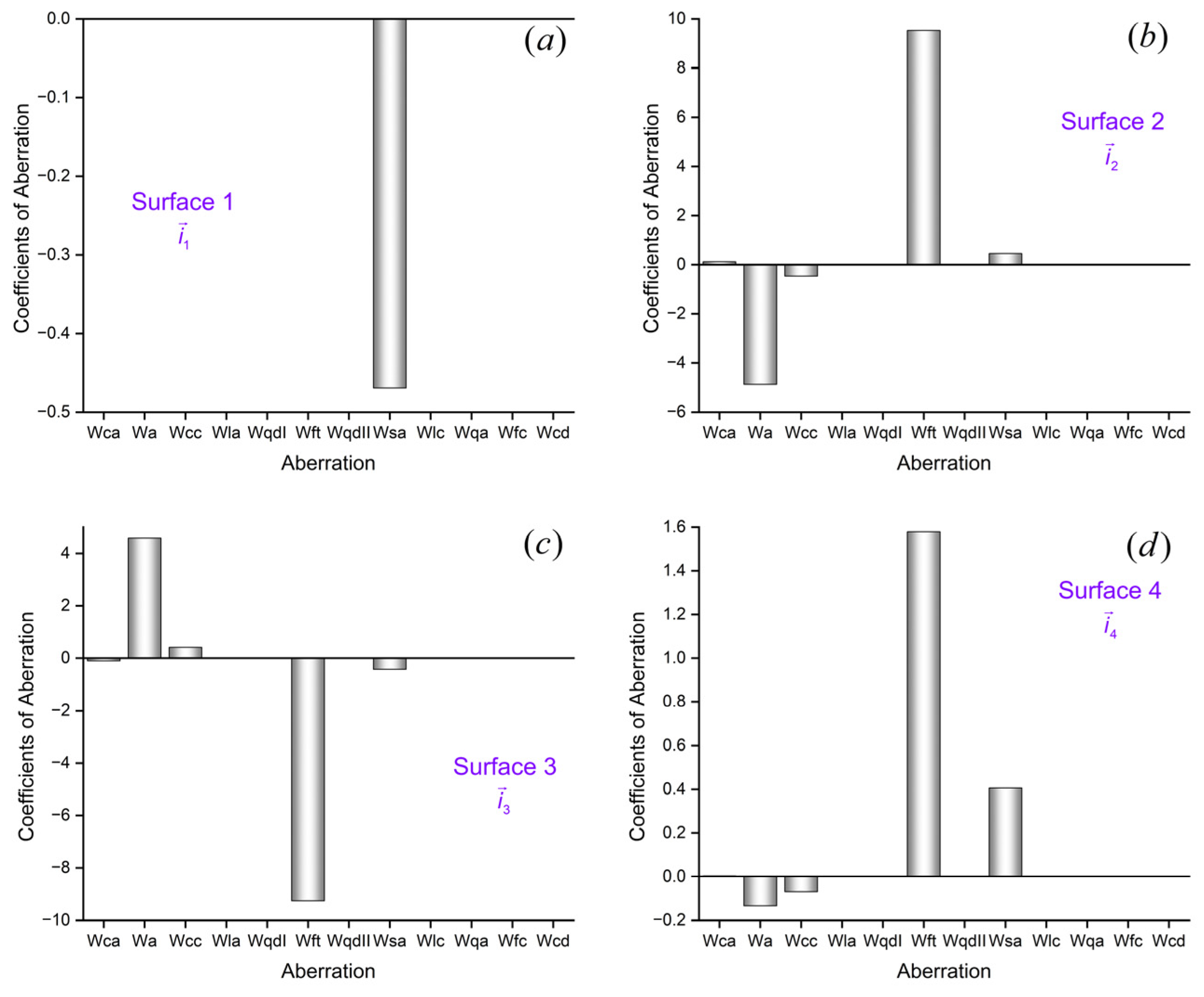
In a doubly telecentric projection optical system with high imaging quality, a dual-prism system, as shown in Figure 2 is used to quantitatively verify the aberrations generated by the rotation of each surface by the prism. A 100 mm × 100 mm the field of view is used to represent aberration characteristics. The structural parameters (wedge angle, refractive index, thickness) of the two prisms are consistent. Prism 2 rotates around a mechanical axis relative to Prism 1. The aberration orientation of the beam on each surface is represented by i n u m b e r ( n u m b e r = 1 , 2 , 3 , 4 ) . The theoretical calculation values of aberration are shown in Figure 5.

3.2. Aberration Result Verification

In addition to combining the aberration coefficients of different planar symmetric systems, aberration coefficients can also be extracted from the optical path differences and ray aberrations of a few real rays [23,24]. The results of these two methods correspond to each other but are slightly different.
Currently, it is straightforward to establish compensation device models for various states using computer simulation software. Simulation software has the ability to track real light rays and provide actual aberrations. The theoretical results, calculated using the expressions, can then be compared with actual ray-tracing data to verify the accuracy and effectiveness of the results.
The aberration methods calculated from theory and data fitting can be written into ZEMAX macros, making it convenient to apply them to different adjustment states of compensation devices. We have tested the system under various adjustment states using this macro, and the results confirm that the expression is accurate.
Among these aberrations, distortion is purely a mapping error and will not cause image blurring. Therefore, distortion can be corrected through post-processing of the image. In some applications, post-processing may not be possible, or distortion should be minimized to reduce post-processing errors. For this reason, we specifically emphasize the types of distortions in the aberration field. The distortion satisfies the following equation:
ε = 1 n u ρ W ( H , ρ ) = 1 n u ρ 1 j W m j ( H ρ ) + 1 j W a j i j H i j ρ + 1 j W q d I j i j ρ H H + 1 j W q d I I j i j H H ρ + 1 j W c d j ρ ρ H ρ = 1 n u ρ W m ( H ρ ) + W a ( i a H ) ( i a ρ ) + W q d I ( i q d I ρ ) ( H H ) + W q d I I ( i q d I I H ) ( H ρ ) + W c d ( H ρ ) ( H H ) = 1 n u W m ( H ) + W a ( i a ) ( i a H ) + W q d I ( i q d I ) ( H H ) + W q d I I ( H ) ( i q d I I H ) + W c d ( H ) ( H H )
where ε is the lateral aberration vector on the image plane, n is the index of refraction, and u is the marginal ray slope in image space, W m ( H ρ ) , W a ( i a H ) ( i a ρ ) , W q d I ( i q d I ρ ) ( H H ) , W q d I I ( i q d I I H ) ( H ρ ) , and W c d ( H ρ ) ( H H ) are the vector sums of W m j ( H ρ ) , W a j i j H i j ρ , W q d I ( i q d I ρ ) ( H H ) , W q d I I j i j H H ρ , and W c d ( H ρ ) ( H H ) , respectively.
To demonstrate the consistency of the two methods, we calculate the aberrations generated by the prism using system and structural parameters that are identical to those in Section 3.1.
The types and magnitudes of aberrations generated are observed and compared with theoretical values, as shown in Figure 6. It can be seen that the aberration magnitudes obtained by ray tracing are generally consistent with the theoretical values. This article focuses on the simpler and more common cases of rotating prisms. The error between the theoretical and actual values of these two examples is partly due to the generation of induced aberrations and higher-order aberrations during the adjustment process. Additionally, an important source of error stems from the approximation used in the aberration formula. To make the aberration formula more accurate, the field vector and pupil vector should be as small as possible; however, this condition is generally not met, leading to an increase in the error. In a rotating prism, the effect of aberrations and the mechanisms and analysis of errors caused by the increase of field vectors and pupil vectors are complex, which is an area for future research.

4. Compensator Design and Simulation Verification

The compensation capability of compensation devices is inherently limited. In order to effectively compensate for the image plane while maintaining appropriate image quality, it is crucial that the magnitude of the introduced aberrations remains within an acceptable range. The servo control performance of the image compensation system is closely related to the imaging quality. Therefore, it is necessary to use the adjustment capability of the compensation device as a strict criterion during its design to verify the effectiveness of image shift compensation. The design steps of compensation devices are as follows:
(1)
Determine the adjustment range of compensation devices based on the control capability of the servo control system.
(2)
Preliminarily determine the structural parameters of the prism.
(3)
Perform compensation analysis and aberration analysis on image plane deformation.
(4)
Based on actual application requirements, taking into account the device structure and aberrations, determine the final structural form.
Due to the errors in the above analysis and other factors, the required compensation may exceed the compensation range of the compensation device. To avoid exceeding the compensation range, an adjustment margin can be incorporated into the prism parameter design.
Based on this, we use the 8.5th generation glass substrate as an example and apply the designed compensating device for compensation. The design indicators are shown in Table 1.
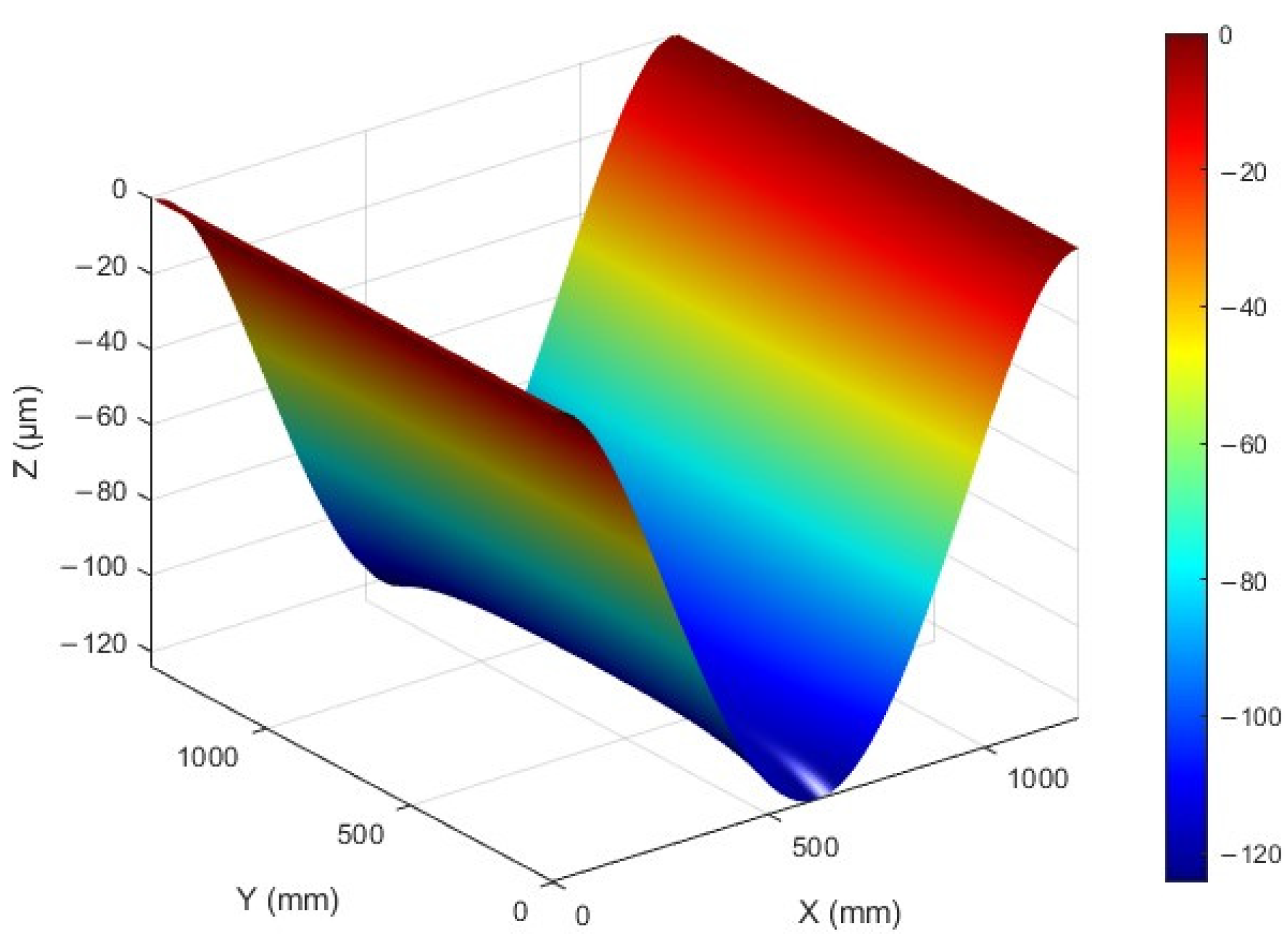
The mask template adopts a natural hanging deformation design, with dimensions of 1220 mm × 1400 mm × 13 mm. The long side is calculated based on simple fixation and simulated using COMSOL (all simulations were performed on personal computers equipped with AMD R7-4800H CPU), and the deformation under its own weight is shown in Figure 7.
As shown in Figure 8, there are 11 doubly telecentric projection optical systems distributed along the short side, each occupying approximately 100 mm of scanning exposure length. The reference wavelength is 0.365 µm, and the NA is 0.1. Therefore, the depth of focus of the system is approximately ±18 µm. The maximum deformation of the mask template (123 µm) far exceeds the depth of focus of the doubly telecentric projection optical system. The image plane deformation of each system is expected to be controlled within 10 µm.
Based on the above calculation, the doubly telecentric projection optical system at different positions needs to adjust the various parameters of the compensation device according to different image plane positions. The schematic diagram of the doubly telecentric projection optical system and compensation device is shown in Figure 9.
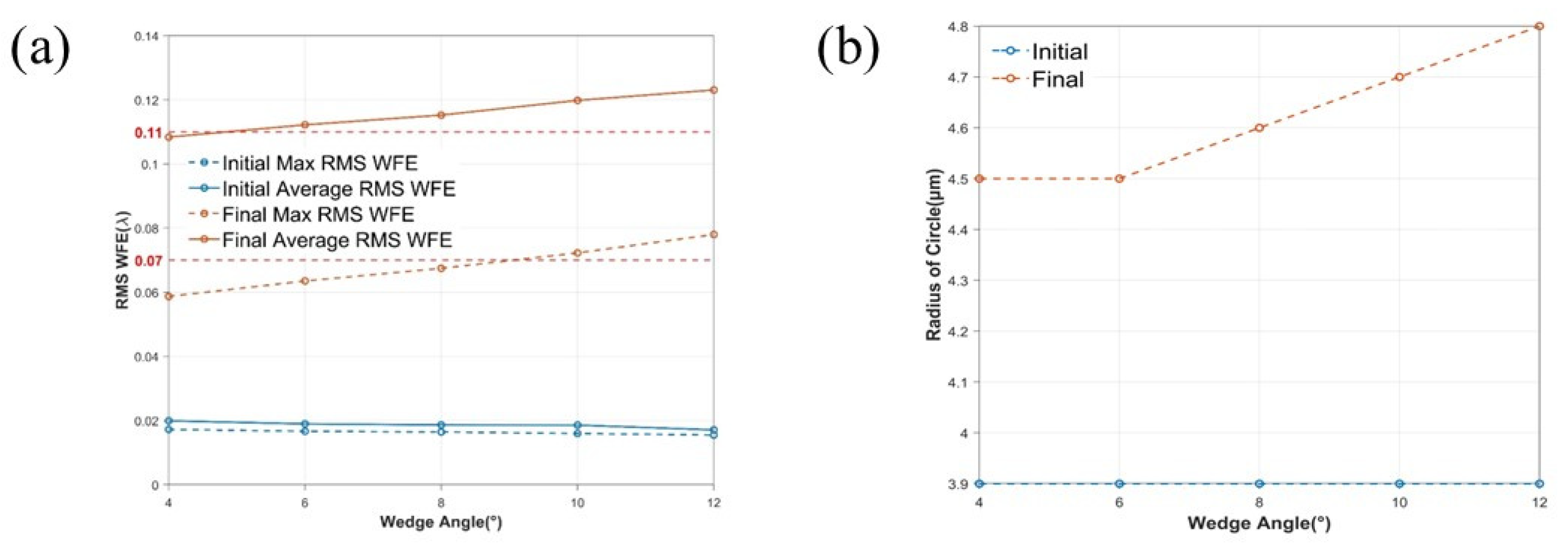
Prisms have two parameters: wedge angle and center thickness, and are made of fused silica with high ultraviolet transmittance. The center thickness is set to 20 mm to ensure good deformation resistance. The influence of different wedge angles on the doubly telecentric projection optical system was compared using Zemax 2023 software. Figure 10a shows the initial RMS WFE of prisms with different wedge angles and the maximum RMS WFE during the adjustment process. Figure 10b shows the variation of the radius of a circle with an encircled energy fraction higher than 0.9 with different wedge angles. The smaller the wedge angle during the adjustment process, the smaller the aberration generated, and the higher the energy concentration. This is because the OAR angle, which is included in the aberration coefficient, is the main factor for all plane symmetric aberrations. Reducing the surface tilt angle can effectively reduce the contribution of surface aberration. To avoid collisions during the rotation of the prism, a wedge angle of 4° is selected for the prism.
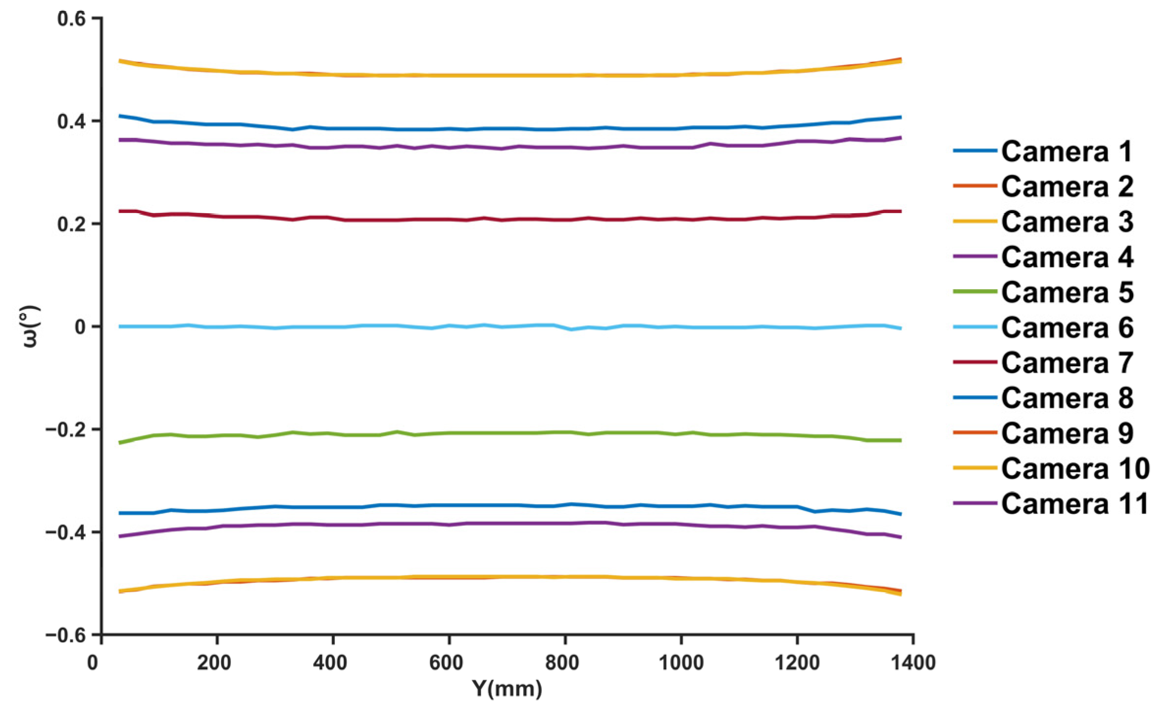
The parameters of the compensation device are set according to the doubly telecentric projection optical system. Increasing the wedge angle will reduce the step size, but increases the system’s aberration, and it is limited by resolution, which reduces the compensation effect. To meet the 5″ angle resolution requirement, the rotation angle is processed, and a curve is drawn. The schematic diagram in Figure 11 shows the adjustment of prism rotation angle with different positions of image plane tilt. Its maximum travel is within 0.6°. Additionally, the telecentricity is 0.05 mrad, which meets the design specifications.
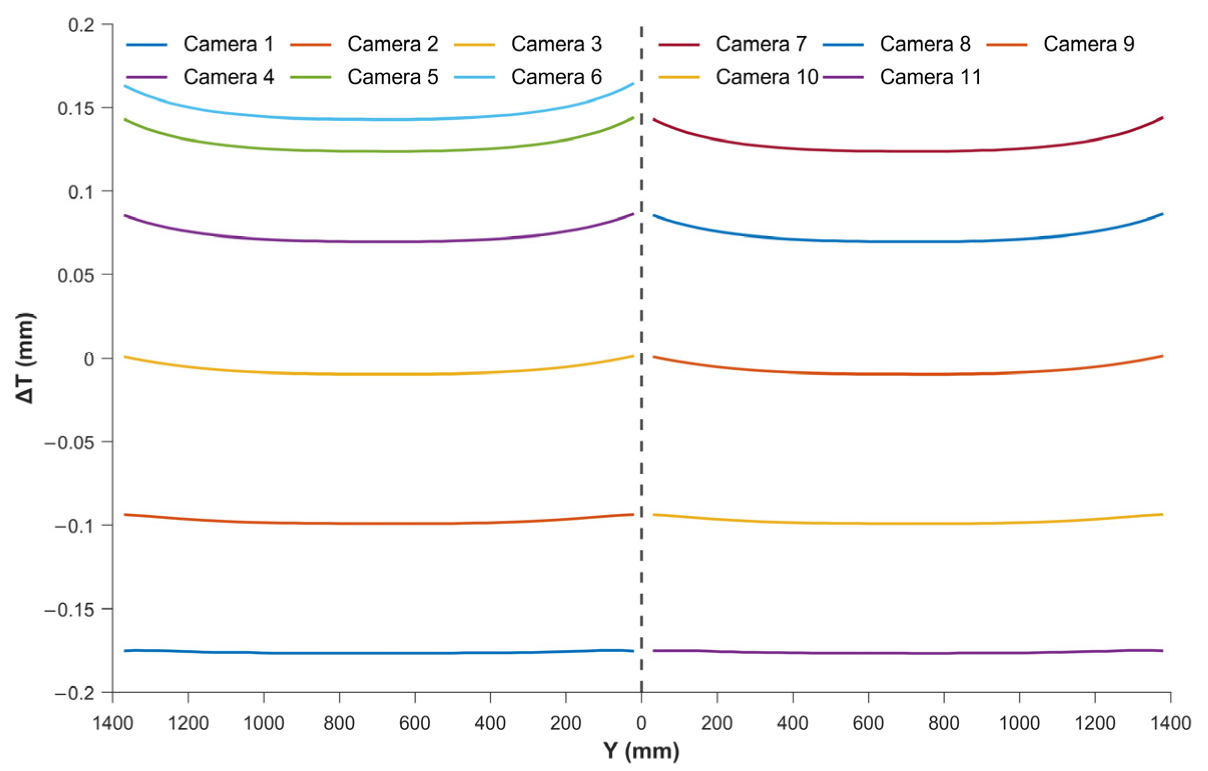
To meet the displacement resolution of 2 µm, the thickness of the prism in the optical path is processed, and the curve is plotted. Figure 12 shows the schematic diagram of adjusting the distance of prism thickness variation in the optical path with different positions of image plane defocus. Its maximum travel is within 0.2 µm. The sensitivity of adjusting the image plane is 28.125 nm/µm, meaning that moving the prism diagonally by 1 µm will change the focal plane by 28.125 nm. This low sensitivity and minimal machinery and control requirements make it very easy to achieve precise control of the focusing surface.
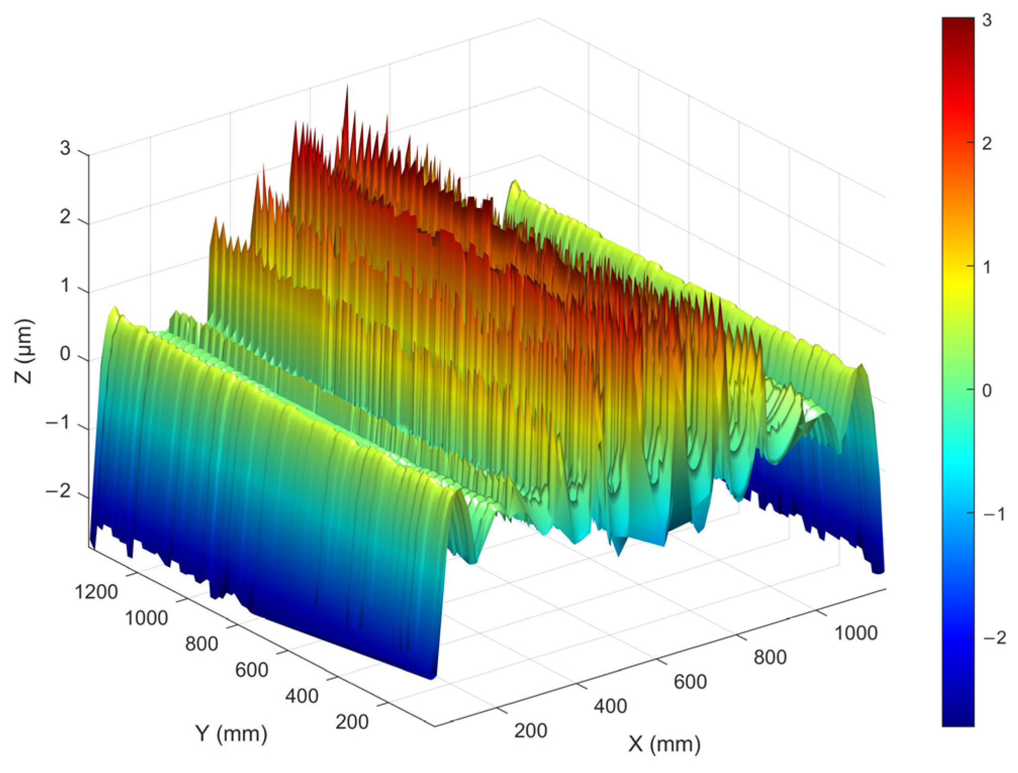
The deformation after compensation using the dual-prism designed with the above parameters is shown in Figure 13. Table 2 shows the results of compensating for image plane deformation using different compensation methods. Among them, only defocusing compensation still results in a significant amount of deformation, with a maximum deformation of 20.087 µm, which exceeds the depth of focus range of the doubly telecentric projection optical system. After applying both defocusing and tilt compensation, the maximum deformation is 3.011 µm, which is within the depth of focus range of the doubly telecentric projection optical system, proving the necessity of tilt compensation. Under the condition of acceptable image quality, effective compensation for image plane deformation has been achieved. Due to the advanced and specialized technical nature of this research area and the limited quantitative data on the available compensation methods published for confidentiality reasons, relevant publicly available comparative data could not be found.

5. Conclusions

This study introduces a high-precision dual-prism compensation method based on aberration theory, aiming to solve the problem of image plane deformation in doubly telecentric projection optical systems. Through the design and simulation verification of the dual-prism compensation device, the proposed method has demonstrated significant improvements in image quality, with image plane deformation reduced to 3.011 μm, max RMS WFE less than 0.11 λ, and average RMS WFE less than 0.07 λ. These results fall within the acceptable range of high-precision systems and exhibit good telecentricity. This work not only improves the accuracy of optical compensation but also provides a systematic, analysis-driven deformation compensation framework that is more predictable and accurate than existing methods.
When adjusting the defocusing tilt compensation device to compensate for image plane deformation, different adjustment methods can produce different aberrations and even lead to an increase in induced aberrations and higher-order aberrations. Since the aberrations generated by each surface have been quantified, it is possible to eliminate aberrations during the adjustment process and reduce residual aberrations by adding free-form surfaces to appropriate surfaces according to the needs of the application scenario, thus achieving better compensation.
In the actual experiment, manufacturing, assembly, and material errors, among other factors, will affect the imaging quality of the doubly telecentric projection optical system. Further experimental verification is planned in subsequent studies, with the method being supplemented and refined based on the experimental results.

Author Contributions

Conceptualization, Y.X. and H.W.; Methodology, Y.X., G.S. and H.Y.; Software, J.Z. and Y.H.; Validation, H.Y., J.Z. and Y.H.; Writing—original draft, Y.X.; Writing—review & editing, Y.X., H.W., G.S., H.Y., J.Z. and Y.H.; Supervision, H.W. and G.S. All authors have read and agreed to the published version of the manuscript.

Funding

This research was funded by National Natural Science Foundation of China (NSFC) (62475122).

Institutional Review Board Statement

Not applicable.

Informed Consent Statement

Not applicable.

Data Availability Statement

The original contributions presented in the study are included in the article, further inquiries can be directed to the corresponding author.

Conflicts of Interest

The authors declare no conflicts of interest.

References

  1. Sandstrom, T.; Wahlsten, M.; Sundelin, E.; Hansson, G.; Svensson, A. Mask and Lithography Techniques for FPD. In Proceedings of the 31st European Mask and Lithography Conference, Eindhoven, The Netherlands, 22–23 June 2015; Behringer, U.F.W., Finders, J., Eds.; SPIE: Bellingham, WA, USA, 2015; Volume 9661, p. 966103. [Google Scholar]
  2. Flagello, D.G. Recent Developments and Concepts in Optical Exposure Technology. In Proceedings of the Optical Microlithography XXXIV, SPIE Advanced Lithography, Virtual, CA, USA, 22–27 February 2021; SPIE: Bellingham, WA, USA, 2021; Volume 11613, p. 1161304. [Google Scholar]
  3. Rössler, K.F.; Diez, S.; Wahl, M.; Chen, T. Overlay Results on Halftone FPD Photomasks with an Advanced High-Productivity Lithography System. In Proceedings of the Photomask Technology, Monterey, CA, USA, 20 November 2024; Melvin, L.S., Kim, S.-S., Eds.; SPIE: Bellingham, WA, USA, 2024; p. 87. [Google Scholar]
  4. Kobayashi, S.; Yoshida, K.; Miyoshi, M.; Yoshikawa, Y. New Half-Tone Lithography Uses for FPD Proximity Printing. In Proceedings of the Photomask Japan 2018: XXV Symposium on Photomask and Next-Generation Lithography Mask Technology, Yokohama, Japan, 12 June 2018; Takehisa, K., Ed.; SPIE: Bellingham, WA, USA, 2018; p. 7. [Google Scholar]
  5. Shafer, D.R. 25 Years of Progress in Lithographic Optics Design Methods. In Proceedings of the Current Developments in Lens Design and Optical Engineering XXV, San Diego, CA, USA, 1 October 2024; Sun, C.-C., Mahajan, V.N., Thibault, S., Eds.; SPIE: Bellingham, WA, USA, 2024; p. 8. [Google Scholar]
  6. Ohmura, Y.; Tsuge, Y.; Hirayama, T.; Ikezawa, H.; Inoue, D.; Kitamura, Y.; Koizumi, Y.; Hasegawa, K.; Ishiyama, S.; Nakashima, T.; et al. High-Order Aberration Control during Exposure for Leading-Edge Lithography Projection Optics. In Proceedings of the Optical Microlithography XXIX, San Jose, CA, USA, 15 March 2016; Erdmann, A., Kye, J., Eds.; SPIE: Bellingham, WA, USA, 2016; p. 97800Y. [Google Scholar]
  7. Kaczorowski, A.; Gordon, G.S.D.; Wilkinson, T.D. Adaptive, Spatially-Varying Aberration Correction for Real-Time Holographic Projectors. Opt. Express 2016, 24, 15742. [Google Scholar] [CrossRef] [PubMed]
  8. Rajaeipour, P. Deformable Phase Plate—A New Technology for Plug-and-Play Adaptive Optics. In Proceedings of the Imaging and Applied Optics Congress 2022 (3D, AOA, COSI, ISA, pcAOP), Vancouver, BC, Canada, 11–15 July 2022; Optica Publishing Group: Washington, DC, USA, 2022; p. OTh4B.3. [Google Scholar]
  9. Watabe, A.; Harada, D.; Takeuchi, M.; Ishitsuka, Y. Shin-Etsu Super-High-Flat Substrate for FPD Panel Photomask. In Proceedings of the Photomask Japan 2018: XXV Symposium on Photomask and Next-Generation Lithography Mask Technology, Yokohama, Japan, 12 June 2018; Takehisa, K., Ed.; SPIE: Bellingham, WA, USA, 2018; p. 5. [Google Scholar]
  10. Yagami, T.; Kambayashi, T.; Azumi, M. Correction of Deflection under Mask’s Own Weight by Bending Mask Technology. In Proceedings of the Photomask Technology 2016, San Jose, CA, USA, 5 October 2016; Kasprowicz, B.S., Buck, P.D., Eds.; SPIE: Bellingham, WA, USA, 2016; p. 99851X. [Google Scholar]
  11. Tominaga, S.; Kawai, K.; Yamamoto, H. Projecting a Flat Plane to a Spherical Surface by Use of a Compensation Mirror. Opt. Rev. 2019, 26, 411–421. [Google Scholar] [CrossRef]
  12. Acosta, E.; Sasián, J. Phase Plates for Generation of Variable Amounts of Primary Spherical Aberration. Opt. Express 2011, 19, 13171. [Google Scholar] [CrossRef]
  13. Sasian, J.; Acosta, E. Generation of Spherical Aberration with Axially Translating Phase Plates via Extrinsic Aberration. Opt. Express 2014, 22, 289. [Google Scholar] [CrossRef] [PubMed]
  14. Wilcox, C.C.; Andrews, J.R.; Restaino, S.R.; Teare, S.W.; Payne, D.M.; Krishna, S. Analysis of a Combined Tip-Tilt and Deformable Mirror. Opt. Lett. 2006, 31, 679. [Google Scholar] [CrossRef] [PubMed]
  15. Japan Display Inc. Exposure Device and Method. Japanese Patent JP 4211272 B2, 21 January 2009.
  16. Shanghai Micro Electronics Equipment Co., Ltd. Adjusting Device and Method for Exposure Device. U.S. Patent US 10197919 B2, 5 February 2019. [Google Scholar]
  17. Yoshida, K. Technical Trends of Large-Size Photomasks for Flat Panel Displays. In Proceedings of the 33rd European Mask and Lithography Conference, Dresden, Germany, 28 September 2017; Behringer, U.F.W., Finders, J., Eds.; SPIE: Bellingham, WA, USA, 2017; p. 5. [Google Scholar]
  18. Sasian, J.M. How to Approach the Design of a Bilateral Symmetric Optical System. Opt. Eng. 1994, 33, 2045. [Google Scholar] [CrossRef]
  19. Sasian, J.M. Aberrations from a Prism and a Grating. Appl. Opt. 2000, 39, 34. [Google Scholar] [CrossRef] [PubMed]
  20. Moore, L.B.; Hvisc, A.M.; Sasian, J. Aberration Fields of a Combination of Plane Symmetric Systems. Opt. Express 2008, 16, 15655. [Google Scholar] [CrossRef]
  21. Li, A.; Zhao, Z.; Liu, X.; Deng, Z. Risley-Prism-Based Tracking Model for Fast Locating a Target Using Imaging Feedback. Opt. Express 2020, 28, 5378. [Google Scholar] [CrossRef]
  22. Liu, Y.; Steidle, J.; Rolland, J.P. Intrinsic Aberration Coefficients for Plane-Symmetric Optical Systems Consisting of Spherical Surfaces. J. Opt. Soc. Am. A 2023, 40, 378. [Google Scholar] [CrossRef] [PubMed]
  23. Herman, E.; Sasian, J. Aberration Considerations in Lens Tolerancing. Appl. Opt. 2014, 53, 341. [Google Scholar] [CrossRef] [PubMed]
  24. Yuan, S.; Sasian, J. Aberrations of Anamorphic Optical Systems I: The First-Order Foundation and Method for Deriving the Anamorphic Primary Aberration Coefficients. Appl. Opt. 2009, 48, 2574. [Google Scholar] [CrossRef] [PubMed]
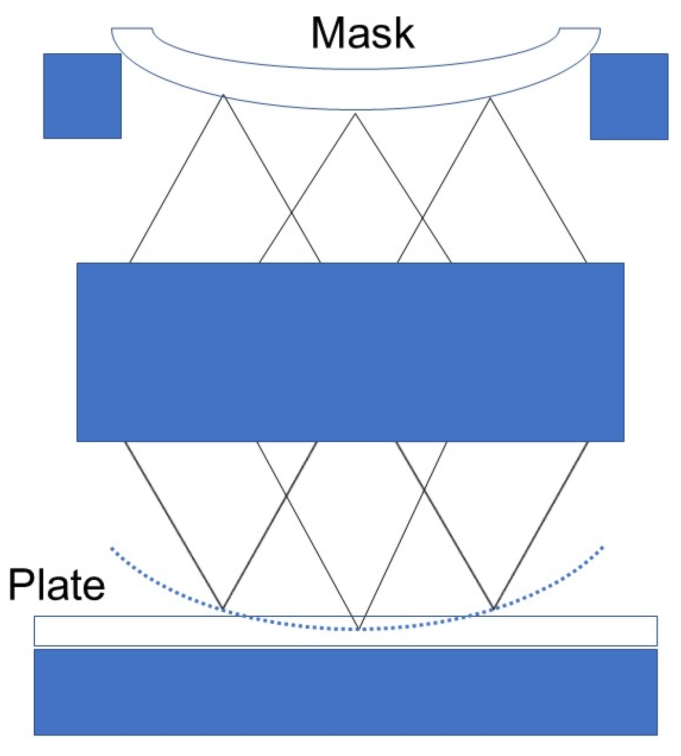
Figure 1. Diagram of Image Surface Deformation.
Applsci 15 02691 g001
Figure 2. Schematic diagram of image plane deformation compensation model and adjustment method. (a) Schematic diagram of axial movement and oblique movement. (b) Schematic diagram of prism rotation.
Applsci 15 02691 g002
Figure 3. Schematic diagram of image plane deformation compensation model. (a,b) represent different adjustment states respectively.
Applsci 15 02691 g003
Figure 4. Schematic Diagram of Adjusting the Image Plane with Different Parameters of Dual-Prism.
Applsci 15 02691 g004
Figure 5. Aberrations generated on each surface. (ad) represent the magnitude and direction of aberrations produced by the four surfaces respectively.
Applsci 15 02691 g005
Figure 6. Comparison between theoretical calculation values of aberration coefficients in x and y directions and ray tracing values. (a) is the aberration coefficient in X direction, (b) is the aberration coefficient in Y direction.
Applsci 15 02691 g006
Figure 7. Schematic diagram of mask template deformation.
Applsci 15 02691 g007
Figure 8. Schematic diagram of field of view stitching.
Applsci 15 02691 g008
Figure 9. Schematic diagram of optical system and compensation device.
Applsci 15 02691 g009
Figure 10. (a) Dual-Prism RMS WFE and Maximum RMS WFE in Initial State; (b) the radius of a circle with an encircled energy fraction higher than 0.9 varies with different wedge angles.
Applsci 15 02691 g010
Figure 11. Schematic diagram of adjusting the rotation angle of prism 2 with the tilt of the image plane at different positions.
Applsci 15 02691 g011
Figure 12. Schematic diagram of prism thickness transformation and image plane defocus adjustment at different positions.
Applsci 15 02691 g012
Figure 13. Schematic diagram of actual deformation compensation residuals.
Applsci 15 02691 g013
Table 1. Specifications of the doubly telecentric projection optical system.
ParameterSpecification
Displacement resolution2 µm
Angular resolution5″
PV of the surface deformation error10 µm
RMS of the surface deformation error1 µm
Max RMS WFE0.11λ
Average RMS WFE0.07λ
Telecentricity<0.4 mrad
Table 2. Comparison of compensation results.
Mode of CompensationPeakValleyRMS
None0−123 µm75.264 µm
Defocus20.087 µm−19.028 µm6.700 µm
Defocus and tilt3.011 µm2.738 µm0.668 µm
Disclaimer/Publisher’s Note: The statements, opinions and data contained in all publications are solely those of the individual author(s) and contributor(s) and not of MDPI and/or the editor(s). MDPI and/or the editor(s) disclaim responsibility for any injury to people or property resulting from any ideas, methods, instructions or products referred to in the content.