High-Precision Compensation Method for Image Plane Deformation in the Doubly Telecentric Projection Optical System

 ,
,
Abstract
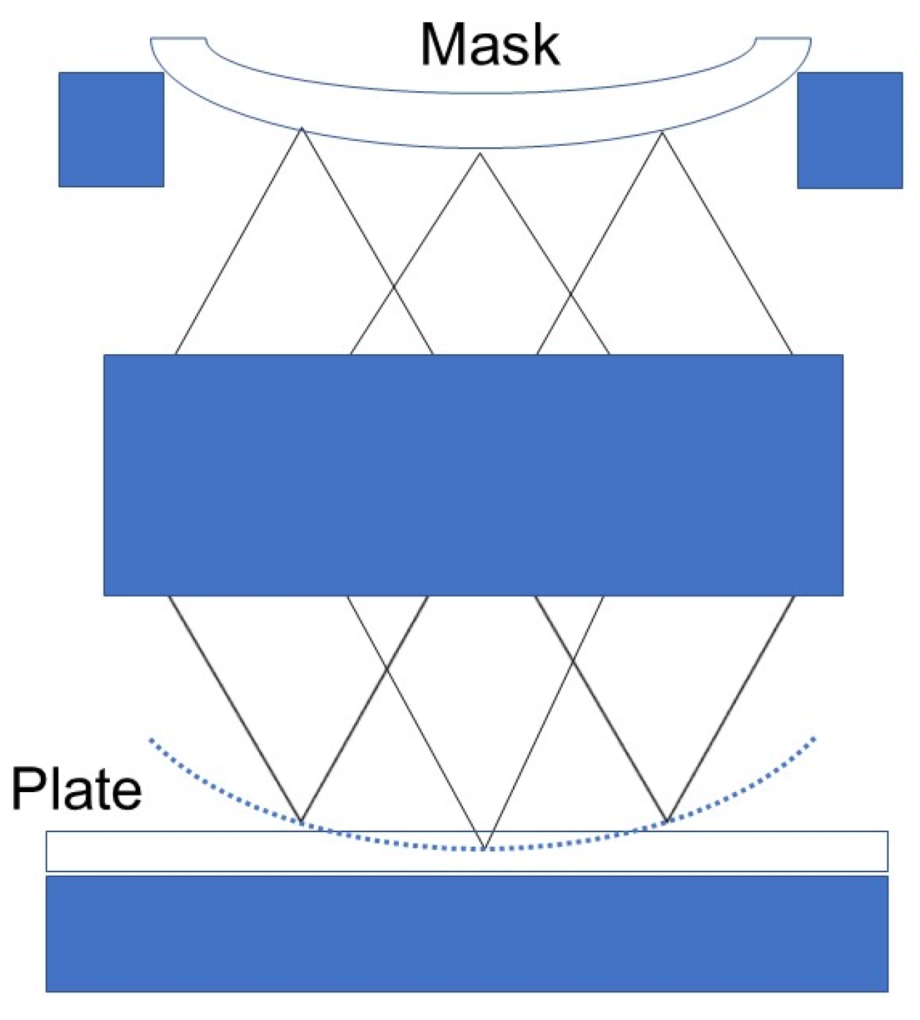
1. Introduction
2. Construction of the Defocus and Tilt Compensation Theoretical Model
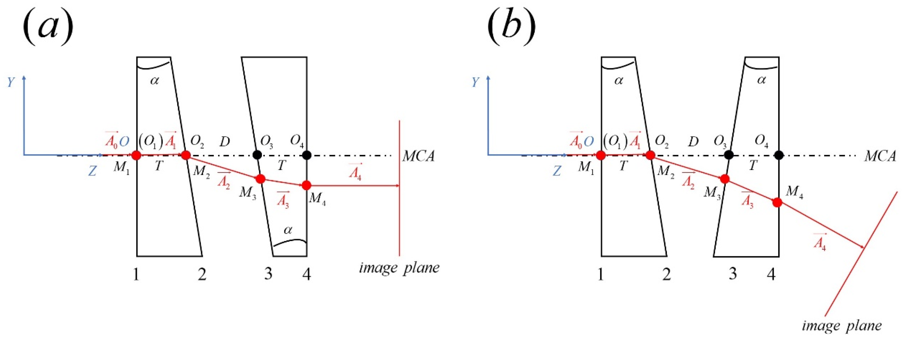
2.1. Dual-Prism Compensation Theoretical Model
2.2. Compensation Strategy and Process
- (1)
- Calculate the rotation angle of the prism based on the tilt of the image plane. Using Snell’s law to obtain the cosine of the direction of light rays, the rotation matrix can be obtained from the normal vectors before and after rotation, and then the rotation angle of the prism can be obtained through the formula.where is the normal vector of surface 3 after rotation, is the normal vector of surface 3 before rotation, is the rotation matrix.
- (2)
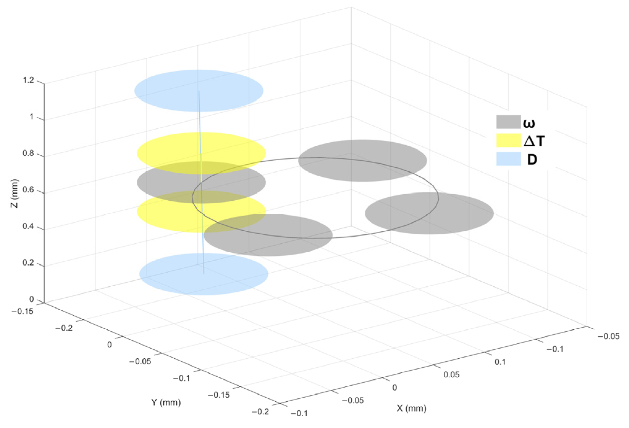
- Adjust the parameters to compensate for the image plane displacement in the x- and y-directions. Typically, two parallel plates tilted around the x- and y-axes are used in the exposure optical path to control lateral displacement. Therefore, this step can be optionally omitted based on practical requirements.
- (3)
- Adjust the parameters to compensate for the image plane movement in the z-direction. This adjustment is achieved through the oblique movement of the second wedge prism.
3. Theoretical Model and Computational Analysis of Aberrations in Double Prism Compensation Devices
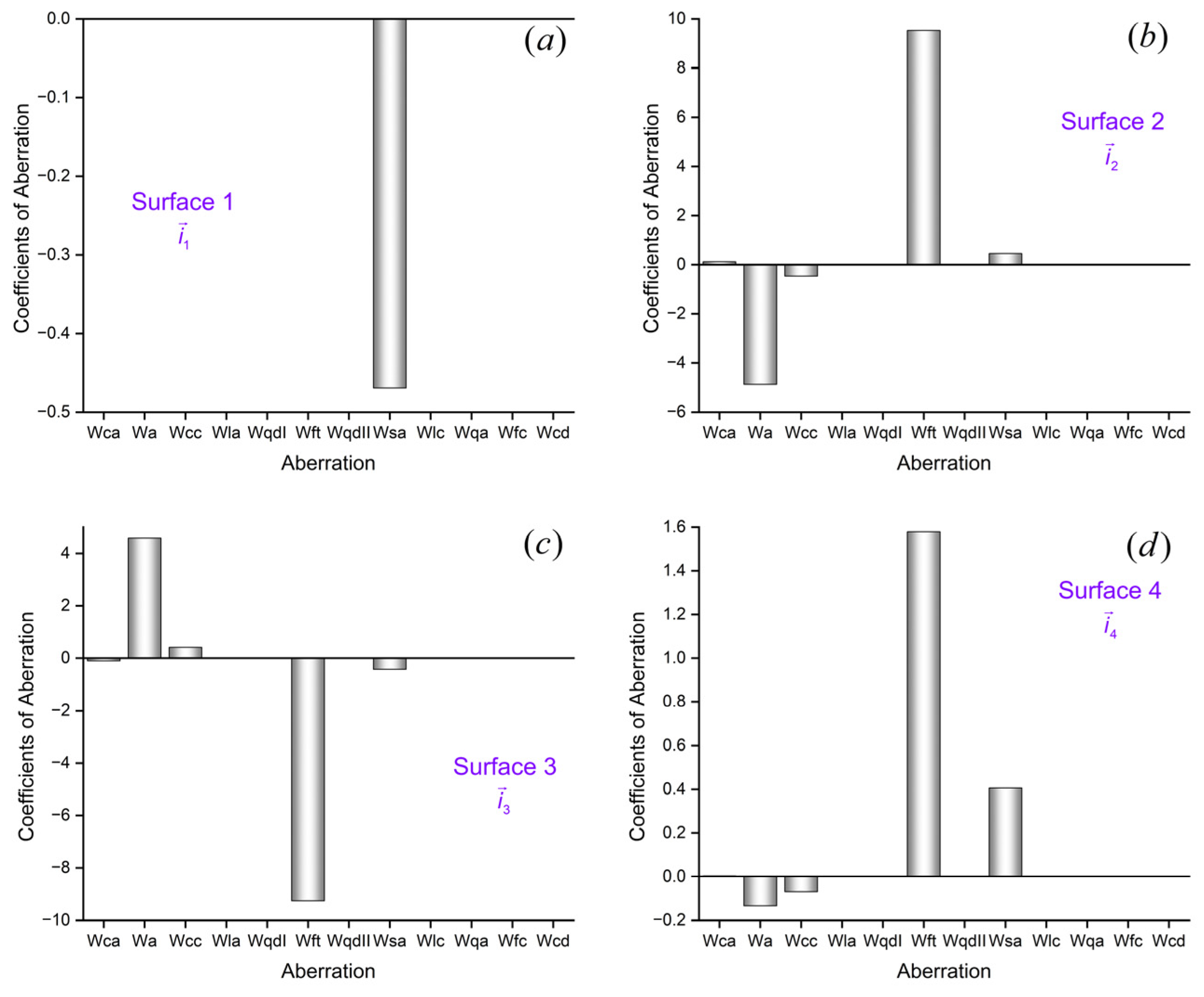
3.1. Aberration Calculation
3.2. Aberration Result Verification
4. Compensator Design and Simulation Verification
- (1)
- Determine the adjustment range of compensation devices based on the control capability of the servo control system.
- (2)
- Preliminarily determine the structural parameters of the prism.
- (3)
- Perform compensation analysis and aberration analysis on image plane deformation.
- (4)
- Based on actual application requirements, taking into account the device structure and aberrations, determine the final structural form.
5. Conclusions
Author Contributions
Funding
Institutional Review Board Statement
Informed Consent Statement
Data Availability Statement
Conflicts of Interest
References
- Sandstrom, T.; Wahlsten, M.; Sundelin, E.; Hansson, G.; Svensson, A. Mask and Lithography Techniques for FPD. In Proceedings of the 31st European Mask and Lithography Conference, Eindhoven, The Netherlands, 22–23 June 2015; Behringer, U.F.W., Finders, J., Eds.; SPIE: Bellingham, WA, USA, 2015; Volume 9661, p. 966103. [Google Scholar]
- Flagello, D.G. Recent Developments and Concepts in Optical Exposure Technology. In Proceedings of the Optical Microlithography XXXIV, SPIE Advanced Lithography, Virtual, CA, USA, 22–27 February 2021; SPIE: Bellingham, WA, USA, 2021; Volume 11613, p. 1161304. [Google Scholar]
- Rössler, K.F.; Diez, S.; Wahl, M.; Chen, T. Overlay Results on Halftone FPD Photomasks with an Advanced High-Productivity Lithography System. In Proceedings of the Photomask Technology, Monterey, CA, USA, 20 November 2024; Melvin, L.S., Kim, S.-S., Eds.; SPIE: Bellingham, WA, USA, 2024; p. 87. [Google Scholar]
- Kobayashi, S.; Yoshida, K.; Miyoshi, M.; Yoshikawa, Y. New Half-Tone Lithography Uses for FPD Proximity Printing. In Proceedings of the Photomask Japan 2018: XXV Symposium on Photomask and Next-Generation Lithography Mask Technology, Yokohama, Japan, 12 June 2018; Takehisa, K., Ed.; SPIE: Bellingham, WA, USA, 2018; p. 7. [Google Scholar]
- Shafer, D.R. 25 Years of Progress in Lithographic Optics Design Methods. In Proceedings of the Current Developments in Lens Design and Optical Engineering XXV, San Diego, CA, USA, 1 October 2024; Sun, C.-C., Mahajan, V.N., Thibault, S., Eds.; SPIE: Bellingham, WA, USA, 2024; p. 8. [Google Scholar]
- Ohmura, Y.; Tsuge, Y.; Hirayama, T.; Ikezawa, H.; Inoue, D.; Kitamura, Y.; Koizumi, Y.; Hasegawa, K.; Ishiyama, S.; Nakashima, T.; et al. High-Order Aberration Control during Exposure for Leading-Edge Lithography Projection Optics. In Proceedings of the Optical Microlithography XXIX, San Jose, CA, USA, 15 March 2016; Erdmann, A., Kye, J., Eds.; SPIE: Bellingham, WA, USA, 2016; p. 97800Y. [Google Scholar]
- Kaczorowski, A.; Gordon, G.S.D.; Wilkinson, T.D. Adaptive, Spatially-Varying Aberration Correction for Real-Time Holographic Projectors. Opt. Express 2016, 24, 15742. [Google Scholar] [CrossRef] [PubMed]
- Rajaeipour, P. Deformable Phase Plate—A New Technology for Plug-and-Play Adaptive Optics. In Proceedings of the Imaging and Applied Optics Congress 2022 (3D, AOA, COSI, ISA, pcAOP), Vancouver, BC, Canada, 11–15 July 2022; Optica Publishing Group: Washington, DC, USA, 2022; p. OTh4B.3. [Google Scholar]
- Watabe, A.; Harada, D.; Takeuchi, M.; Ishitsuka, Y. Shin-Etsu Super-High-Flat Substrate for FPD Panel Photomask. In Proceedings of the Photomask Japan 2018: XXV Symposium on Photomask and Next-Generation Lithography Mask Technology, Yokohama, Japan, 12 June 2018; Takehisa, K., Ed.; SPIE: Bellingham, WA, USA, 2018; p. 5. [Google Scholar]
- Yagami, T.; Kambayashi, T.; Azumi, M. Correction of Deflection under Mask’s Own Weight by Bending Mask Technology. In Proceedings of the Photomask Technology 2016, San Jose, CA, USA, 5 October 2016; Kasprowicz, B.S., Buck, P.D., Eds.; SPIE: Bellingham, WA, USA, 2016; p. 99851X. [Google Scholar]
- Tominaga, S.; Kawai, K.; Yamamoto, H. Projecting a Flat Plane to a Spherical Surface by Use of a Compensation Mirror. Opt. Rev. 2019, 26, 411–421. [Google Scholar] [CrossRef]
- Acosta, E.; Sasián, J. Phase Plates for Generation of Variable Amounts of Primary Spherical Aberration. Opt. Express 2011, 19, 13171. [Google Scholar] [CrossRef]
- Sasian, J.; Acosta, E. Generation of Spherical Aberration with Axially Translating Phase Plates via Extrinsic Aberration. Opt. Express 2014, 22, 289. [Google Scholar] [CrossRef] [PubMed]
- Wilcox, C.C.; Andrews, J.R.; Restaino, S.R.; Teare, S.W.; Payne, D.M.; Krishna, S. Analysis of a Combined Tip-Tilt and Deformable Mirror. Opt. Lett. 2006, 31, 679. [Google Scholar] [CrossRef] [PubMed]
- Japan Display Inc. Exposure Device and Method. Japanese Patent JP 4211272 B2, 21 January 2009.
- Shanghai Micro Electronics Equipment Co., Ltd. Adjusting Device and Method for Exposure Device. U.S. Patent US 10197919 B2, 5 February 2019. [Google Scholar]
- Yoshida, K. Technical Trends of Large-Size Photomasks for Flat Panel Displays. In Proceedings of the 33rd European Mask and Lithography Conference, Dresden, Germany, 28 September 2017; Behringer, U.F.W., Finders, J., Eds.; SPIE: Bellingham, WA, USA, 2017; p. 5. [Google Scholar]
- Sasian, J.M. How to Approach the Design of a Bilateral Symmetric Optical System. Opt. Eng. 1994, 33, 2045. [Google Scholar] [CrossRef]
- Sasian, J.M. Aberrations from a Prism and a Grating. Appl. Opt. 2000, 39, 34. [Google Scholar] [CrossRef] [PubMed]
- Moore, L.B.; Hvisc, A.M.; Sasian, J. Aberration Fields of a Combination of Plane Symmetric Systems. Opt. Express 2008, 16, 15655. [Google Scholar] [CrossRef]
- Li, A.; Zhao, Z.; Liu, X.; Deng, Z. Risley-Prism-Based Tracking Model for Fast Locating a Target Using Imaging Feedback. Opt. Express 2020, 28, 5378. [Google Scholar] [CrossRef]
- Liu, Y.; Steidle, J.; Rolland, J.P. Intrinsic Aberration Coefficients for Plane-Symmetric Optical Systems Consisting of Spherical Surfaces. J. Opt. Soc. Am. A 2023, 40, 378. [Google Scholar] [CrossRef] [PubMed]
- Herman, E.; Sasian, J. Aberration Considerations in Lens Tolerancing. Appl. Opt. 2014, 53, 341. [Google Scholar] [CrossRef] [PubMed]
- Yuan, S.; Sasian, J. Aberrations of Anamorphic Optical Systems I: The First-Order Foundation and Method for Deriving the Anamorphic Primary Aberration Coefficients. Appl. Opt. 2009, 48, 2574. [Google Scholar] [CrossRef] [PubMed]


| Parameter | Specification |
|---|---|
| Displacement resolution | 2 µm |
| Angular resolution | 5″ |
| PV of the surface deformation error | 10 µm |
| RMS of the surface deformation error | 1 µm |
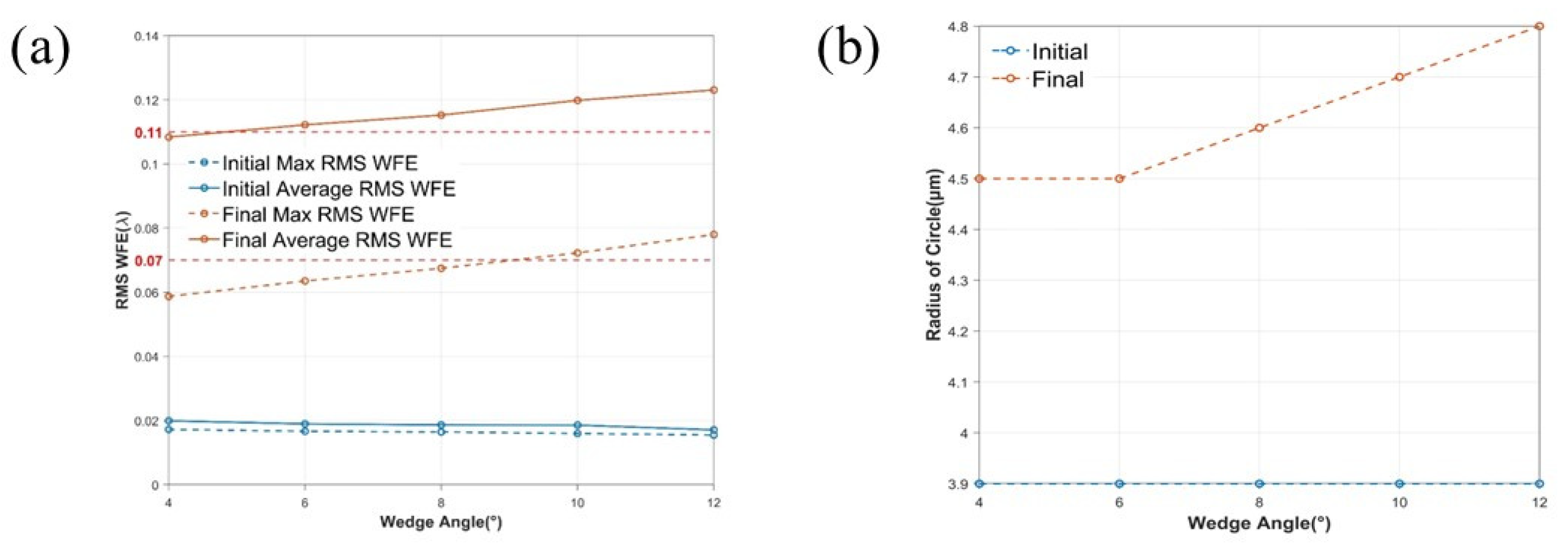
| Max RMS WFE | 0.11λ |
| Average RMS WFE | 0.07λ |
| Telecentricity | <0.4 mrad |
| Mode of Compensation | Peak | Valley | RMS |
|---|---|---|---|
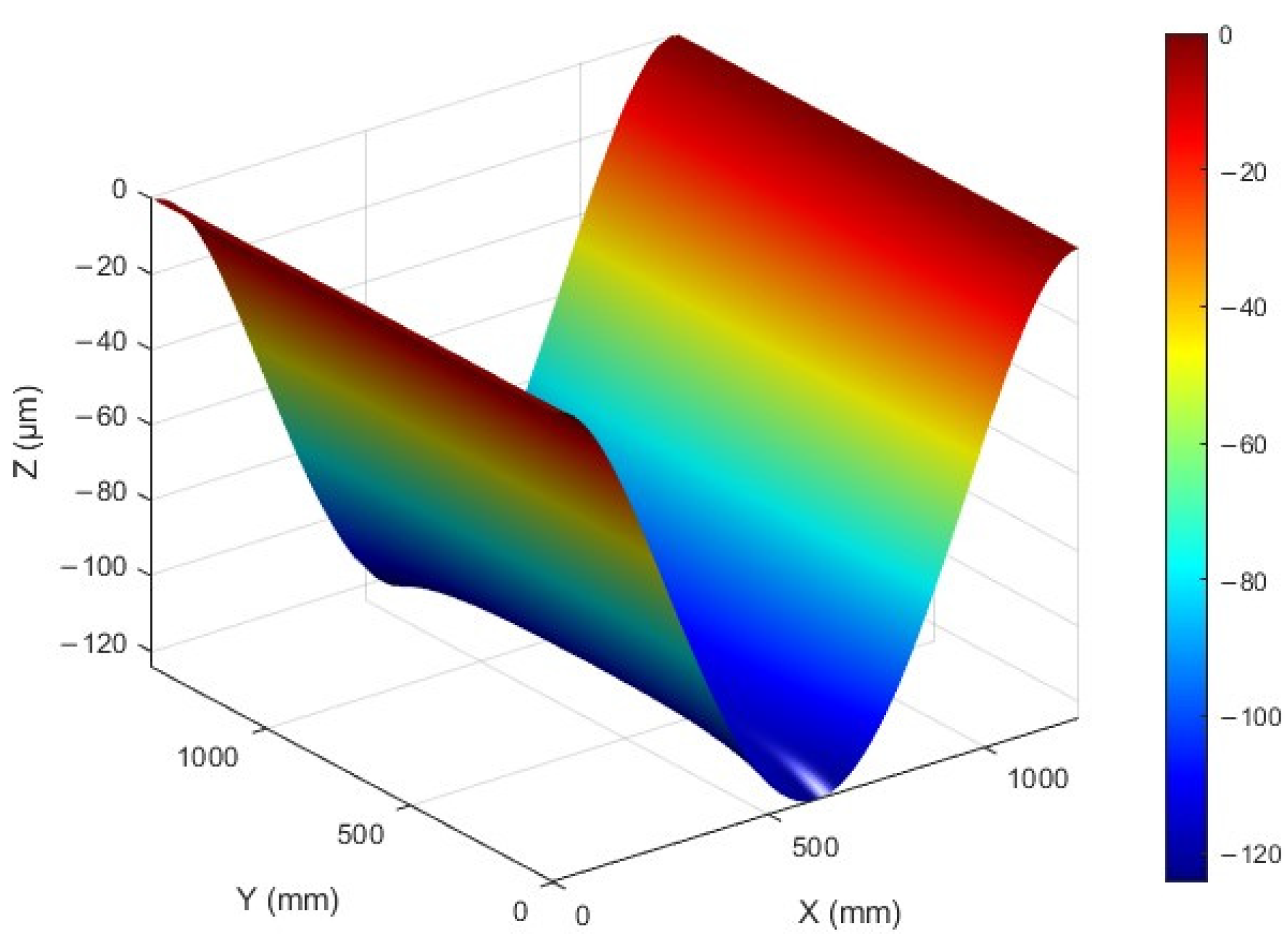
| None | 0 | −123 µm | 75.264 µm |
| Defocus | 20.087 µm | −19.028 µm | 6.700 µm |
| Defocus and tilt | 3.011 µm | 2.738 µm | 0.668 µm |
Disclaimer/Publisher’s Note: The statements, opinions and data contained in all publications are solely those of the individual author(s) and contributor(s) and not of MDPI and/or the editor(s). MDPI and/or the editor(s) disclaim responsibility for any injury to people or property resulting from any ideas, methods, instructions or products referred to in the content. |
© 2025 by the authors. Licensee MDPI, Basel, Switzerland. This article is an open access article distributed under the terms and conditions of the Creative Commons Attribution (CC BY) license (https://creativecommons.org/licenses/by/4.0/).
Share and Cite
Xu, Y.; Wu, H.; Shi, G.; Ye, H.; Zhang, J.; Huang, Y. High-Precision Compensation Method for Image Plane Deformation in the Doubly Telecentric Projection Optical System. Appl. Sci. 2025, 15, 2691. https://doi.org/10.3390/app15052691
Xu Y, Wu H, Shi G, Ye H, Zhang J, Huang Y. High-Precision Compensation Method for Image Plane Deformation in the Doubly Telecentric Projection Optical System. Applied Sciences. 2025; 15(5):2691. https://doi.org/10.3390/app15052691
Chicago/Turabian StyleXu, Yuwei, Hongbo Wu, Guangwei Shi, Haokun Ye, Jipeng Zhang, and Yuqi Huang. 2025. "High-Precision Compensation Method for Image Plane Deformation in the Doubly Telecentric Projection Optical System" Applied Sciences 15, no. 5: 2691. https://doi.org/10.3390/app15052691
APA StyleXu, Y., Wu, H., Shi, G., Ye, H., Zhang, J., & Huang, Y. (2025). High-Precision Compensation Method for Image Plane Deformation in the Doubly Telecentric Projection Optical System. Applied Sciences, 15(5), 2691. https://doi.org/10.3390/app15052691