Article

Analysis of the Impact of the New Two-Lane Shield Tunnel Underpass on the Existing Tunnels

1
College of Civil Engineering and Architecture, Dalian University, Dalian 116622, China
2
Dalian Tunnel and Underground Engineering Center, Dalian University, Dalian 116622, China
*
Author to whom correspondence should be addressed.
Appl. Sci. 2025, 15(5), 2642; https://doi.org/10.3390/app15052642
Submission received: 12 January 2025 / Revised: 17 February 2025 / Accepted: 19 February 2025 / Published: 28 February 2025

Abstract

:
To address the issue of vertical settlement in existing tunnels beneath newly constructed two-lane tunnels, and to mitigate further impacts on tunnel operations, it is essential to investigate the effect of tunnel construction on the integrity of the existing tunnel structure. A calculation formula for the vertical displacement of the existing tunnel is derived by simplifying the calculation model and employing a two-stage analysis method. A three-dimensional numerical model of the double-line shield tunnel beneath the existing tunnel of Dalian Metro Line 4 is established using Midas GTS NX finite element software 2021(v1. 1). The study focuses on the influence of the new tunnel’s excavation on the existing tunnel, examining how various parameters in the shield construction process affect the settlement. Through comparative analysis of theoretical calculations, numerical simulations, and engineering monitoring data, the results indicate that the calculated displacement settlement trends align closely with the numerical simulation and are consistent with the field monitoring data. The findings provide valuable insights for the development of effective protection measures for existing tunnels during shield tunnel construction.

1. Introduction

As urban surface space becomes increasingly saturated, the development and utilization of underground space have garnered growing attention. The construction of new metro tunnels beneath existing ones is becoming more common, as urban space constraints necessitate such projects. However, the construction of new tunnels beneath existing ones inevitably induces deformation in the existing tunnels. Metro operations impose stringent requirements for controlling tunnel deformation. Under-passing construction presents a significant safety risk to existing metro lines and is widely regarded as one of the highest-risk aspects of metro construction.
Academics have extensively studied the settlement effects of new tunnel shield construction on existing tunnels. The research methods primarily include theoretical analyses, field measurements, model tests, and numerical simulations. Sagaseta et al. integrated sink theory into elastic mechanics by treating the strata as an elastic semi-infinite body, thereby determining the impact of strata loss on surface soil displacement [1]. Wei Gang et al. combined the random medium theory and cumulative probability curve to calculate the vertical displacement caused by soil loss and estimated the vertical displacement of the existing tunnel by rotating the staggered platform cooperative deformation model [2]. Gan Xiaolu et al., Zhang Zhiguo et al., and Wang Lixiang et al. proposed a theoretical analytical model by using a two-stage analysis method to predict the impact of the construction of a new shield tunnel on the settlement of an existing tunnel [3,4,5]. Fan Wenhao et al. established an expression for the proximity influence degree and divided the zoning control criteria based on the structural displacement discrimination criterion [6]. Zhang Qiongfang et al. and Si Jinbiao et al. studied the deformation characteristics of existing tunnels and pipelines induced by shield construction through on-site monitoring [7,8]. Gan et al. pointed out that the vertical spacing between two tunnels also affects the deformation of existing tunnels based on the monitoring of construction displacement [9]. Lin Qingtao et al., Zhao Deqianlin et al., and Liu Yong et al. analyzed the disturbance effect on the adjacent existing tunnels during the construction of new tunnels with the help of model tests, and clarified the settlement and deformation law during the process of tunnel penetration [10,11,12], while Michael et al., Golpasand et al. and Moosavi et al. used finite element and discrete element methods to model and deeply analyze the tunnel excavation for different regional characteristics and construction techniques, revealing the mechanisms and characteristics of ground and surface settlement during construction [13,14,15]. Using numerical tests, Wu Xianguo et al. constructed an impact zoning model based on the settlement of existing tunnels [16]. Zhou Zhou et al. investigated the specific impact of shield under-passing on the structural deformation of existing tunnels using FLAC3D v6.0 finite element software combined with field data [17].
Overall, research on underpass construction’s impact on existing tunnels has yielded valuable insights, contributing to a deeper understanding of the issues associated with double-line underpass projects. However, the complexity and regional variability of underground tunnel crossings limits the applicability of current findings. This study employs theoretical calculations, numerical simulations, and on-site measurements to examine the impact of the interval project between Dongfang Road Station and Suoyuwan Station on Dalian Metro Line 4. It analyzes the vertical displacement and additional stress changes in the existing tunnel caused by the proximity of the new tunnel. The study reveals the settlement characteristics of the existing tunnel due to the excavation of the new two-lane tunnel. The accuracy of the numerical simulation model is verified through comparative analysis. An orthogonal test method is applied to simulate and analyze different parameters during shield construction, deriving the settlement behavior under various influencing factors. Additionally, the reliability of the calculation method and numerical simulation results is further validated through comparison with actual monitoring data from the double-line tunnel project.

2. Theoretical Analysis of Vertical Settlement in Underpass Tunnels

2.1. Underlying Assumption

In the process of shield tunnel excavation, it will firstly cause the displacement of the soil above, and then trigger the corresponding deformation of the existing tunnel. In this paper, the following reasonable assumptions are made in the calculation model to simplify the calculation: (1) Considering the nonlinearity and complexity of the foundation, the interaction between the tunnel and the surrounding soil layers is considered through the Pasternak two-parameter foundation model; (2) The existing tunnel is regarded as an Euler-Bernoulli beam; (3) The influence of the existing tunnel is ignored in the calculation of the displacement of the ground soil body; (4) Only the effect of the loss of the soil body caused by the excavation of the new tunnel on the existing tunnel is considered; (5) The arching effect and the drainage consolidation effect of the soil body are ignored in the calculation. The calculation model is shown in Figure 1:

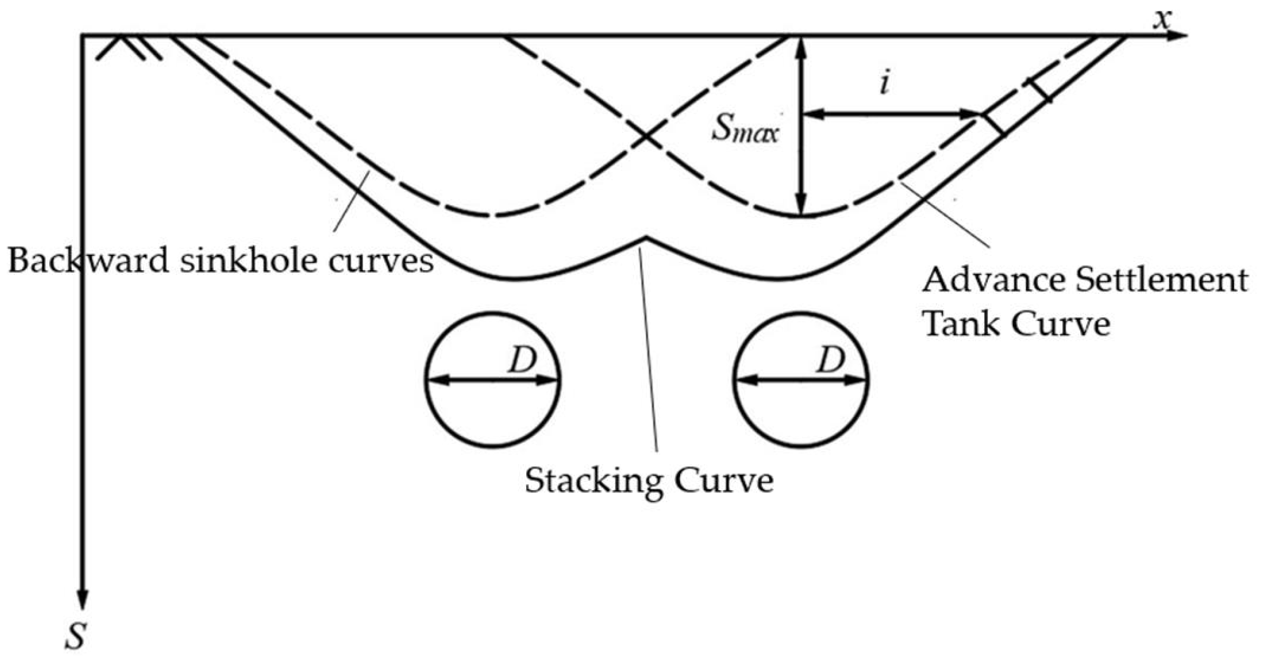
2.2. Modification of Peck’s Formula

In predicting surface settlement caused by subway tunnel construction, the classical Peck’s formula assumes that the surface settlement resulting from underground excavation follows a normal distribution curve. However, due to the idealized assumptions underlying the formula (e.g., homogeneous linear elastic soil), its accuracy may be affected by the complexity of geological conditions in practical applications. To enhance the applicability of Peck’s formula, many researchers have proposed revisions and improvements. Liu Bo et al. supplemented Peck’s formula according to some measured settlement data; they superimposed the ground settlement caused by the shield construction of the left and right tunnels on each other to ascertain the settlement curves as shown in Figure 2, and obtained the formula for the ground settlement induced by the construction of the two tunnels at the same depth of burial [18]:
S x = S max exp x L / 2 2 2 i 2 + S max exp x + L / 2 2 2 i 2
where S(x) is the settlement value at the location where the horizontal distance between the center of symmetry of the axis of the new twin-lane tunnel and the soil cross-section of the strata is, mm; Smax is the maximum value of surface settlement caused by the construction of the shield in the single-lane tunnel, which is calculated as, S max = π D 2 V 1 4 2 π i , mm; D is the diameter of the excavated tunnel, m; V1 is the rate of loss of the strata and i is the width of the sinkhole, m; and L is the spacing of the center of the new twin-lane tunnel, m.
In terms of predicting subsurface settlement, Mair et al. proposed that the width of a sinkhole i at any depth z can be expressed as [19]:
i = K z 0 z
where K is the width parameter of the sedimentation tank, a dimensionless parameter mainly related to the soil property, and z0 is the depth of tunnel, m.
It can be seen from formulas (1) and (2) that under different geological conditions, the width parameter K of the sedimentation tank and the formation loss rate V1 are important parameters affecting the settlement value, and the values can be adjusted to meet the engineering needs of specific areas. For the width parameter of the sedimentation tank, Qi Jun et al. obtained an empirical formula in the form of a hyperbola by fitting all the test and measured data of clay and sandy soil strata [20]:
K z = K s c z / z 0 z / z 0
where Ks is a parameter for the width of the surface settlement trough, c = i / x is a parameter related to the ground conditions, and the fitting of the empirical parameters derived in clay soil resulted in c = 0.323 and in sandy soil c = 0.197.
A tunnel construction ground loss coefficient is introduced, which is related to the directional angle between the new tunnel and the existing tunnel, i.e.,:
V 1 α = λ α λ g V 1
where V1 represents the formation loss coefficient of the settlement curve of the existing line and λα is the geometric correction factor for the formation loss rate of natural subsidence by considering the incline angle of the strike. The geometric correction coefficient of formation loss rate considering the influence of the angle between the tunnel and the existing tunnel can be defined and calculated by the following formula: λ α = 1 cos α ; λg refers to the reduction coefficient of formation loss rate caused by external subsidence reduction measures such as grouting and lifting of existing tunnels. The influence of loss rate caused by measures in caves such as advanced anchor rod, small conduit, and pipe shed is generally directly considered in V1, but not reflected in λg.
In the actual metro tunnel construction process, the degree of deformation between the two tunnels is different due to various conditions. When dealing with the problem of double tunnel excavation, the superposition method cannot be simply used but must fully consider the sequence of excavation [21], and the two tunnels should be calculated independently and then superimposed. The settlement deformation after the double shield tunnel undercutting can be expressed by the following equation:
S ( x ) = S max 1 exp x L / 2 2 2 i 1 2 + S max 2 exp x + L / 2 2 2 i 2 2
where Smax1, Smax2 are the maximum values of surface settlement of the first and second rows of underpass tunnel excavation, respectively, mm, and i1, i2 indicate the width of the sinkhole caused by the first and second rows of tunnel excavation, m, which can be calculated by the correction of the above formula.

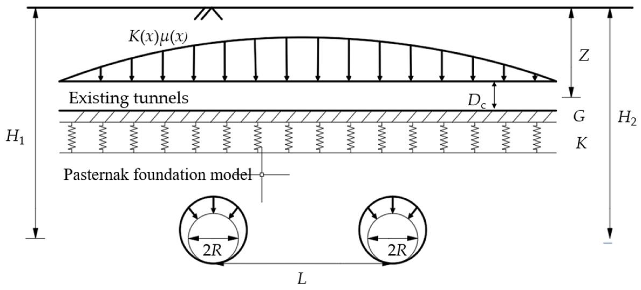
2.3. Two-Lane Tunnel Excavation Prediction of Settlement Calculation for Existing Tunnels

After calculating the free-soil displacements induced by the underpass tunnel, a simplified but effective analytical framework for investigating the effects of the proximity shield construction on the existing tunnel was developed by considering the tunnel as an elastic foundation beam, assuming the soil as a continuous homogeneous elastic medium, and simulating the interactions between the tunnel and the soil with the use of a spring model. A control equation describing the effect of additional soil deformation on the existing tunnel was obtained from the two-stage displacement method [22]:
E I d 4 W x d x 4 + K W x S x = 0
where W(x) is the vertical displacement of the existing tunnel caused by shield excavation, mm; S(x) is the free vertical displacement of the soil body caused by excavation, mm, calculated by equation (5); K = kD, k is the foundation bed coefficient, obtained from the calculation, k = 0.65 E s 1 v 2 E s D 2 E I 12 ; EI is the equivalent bending stiffness of the existing tunnel, N·m2; Es is the modulus of elasticity of the soil, MPa; ν is the Poisson’s ratio of the soil body; and D is the outer diameter of the tunnel of the shield, m.
According to the finite difference principle, the solution of the above differential equation is:
W z x = A sinh λ x sin λ x + B sinh λ x cos λ x + C cosh λ x sin λ x + D cosh λ x cos λ x + W z * x
where A, B, C, and D are integration constants, which can be obtained from the boundary conditions of the existing tunnel, and Wz*(x) is a special solution to meet the requirements.

3. Numerical Simulation of Underpass Construction

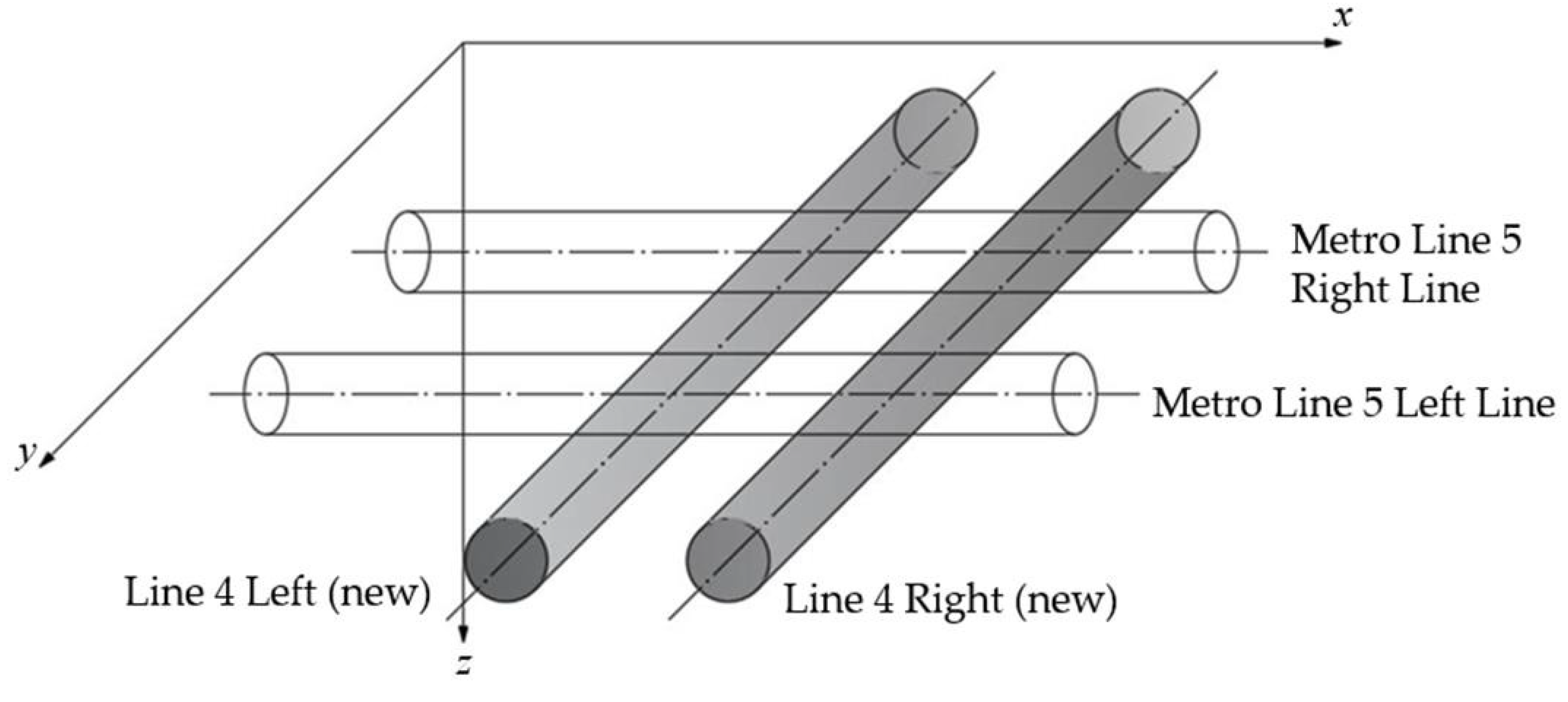
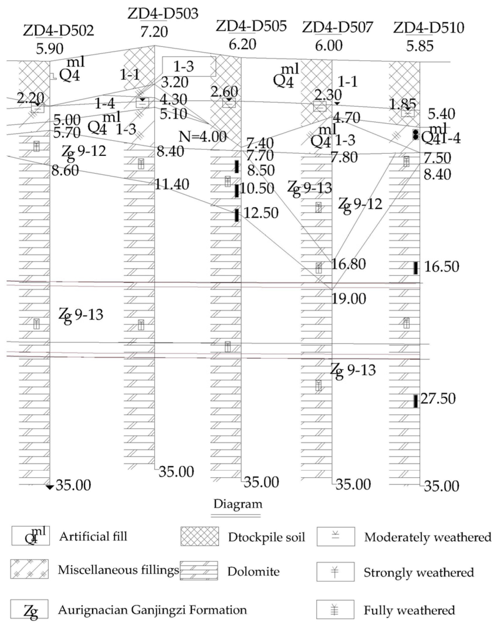
3.1. Project Overview

The new tunnel segment of Dalian Metro Line 4, spanning from Dongfang Road Station to Suoyuwan Station, starts at Dongfang Road Station and runs along the Suoyuwan Business District Central Green Belt in a northwest-to-southeast direction, passing beneath the existing Metro Line 5. The construction of both the left and right tracks employs the shield tunneling method. The shield’s outer diameter is 6.20 m, with an inner diameter of 5.50 m. The width of the tunnel shield is 1.20 m, and the thickness is 0.35 m. The center-to-center distance between the left and right axes is 12.34 m, and the overburden thickness is approximately 25.70 m. The minimum clearance between the arch of the new shield tunnel and the base plate of the existing Line 5 is about 3 m, making this a small-clearance underpass project. Figure 3 shows the spatial location.
According to the site investigation report, Metro Line 4 will pass beneath the existing Metro Line 5. Figure 4 shows the geological cross-section of the specific underpass area. The tunnel of the existing Metro Line 5 lies mainly between the strongly weathered dolomite and the moderately weathered plate dolomite, while the tunnel of the new Metro Line 4 is in the moderately weathered plate dolomite layer. Based on the strata and overburden encountered by the shield, we set the soil chamber pressure at 0.30 MPa and the grouting pressure at 0.30 MPa.

3.2. Numerical Model and Parameter Selection

In this study, we adopted a nonlinear plastic-elastic model to describe the deformation behavior of materials in both the elastic and plastic phases. The linear superposition principle is no longer applicable, as the stress–strain relationship becomes nonlinear in the plastic phase. To address this issue, we treat the elastic and plastic phases separately through stepwise loading, combining it with an iterative method to accurately capture the material’s nonlinear response in the numerical solution. Based on the relative spatial positioning of the new double-lane shield tunnel and the existing tunnel, and applying St. Venant’s principle to eliminate boundary effects, we constructed a numerical model with dimensions of 72 m (length) × 72 m (width) × 60 m (height), consisting of a total of 320,000 cells. The 3D numerical model is shown in Figure 5.
In the model, we used the Mohr–Coulomb damage criterion to describe the constitutive behavior of the geotechnical material. The interaction between the surrounding rock and the tunnel lining is simulated using a contact unit. Both the geotechnical body and the tube sheet grouting are modeled with solid elements. The tube sheet and shield shell are represented by an isotropic linear elasticity constitutive model and plate elements, respectively. Given the use of flexural bolts for the staggered assembly of the new tunnel shield tube sheet, we reduced the elastic modulus using a discount coefficient of 0.85 [23]. For concrete, perimeter rock, and cohesive soils, tension cutoffs were set. The physical and mechanical parameters of the geotechnical materials, as well as the mechanical parameters of the structural materials, are listed in the Table 1 and Table 2.

3.3. Shield Construction Process Simulation

The new tunnel will be constructed using the shield method, and the construction steps are simulated as follows: (1) According to the boundary condition settings, apply normal displacement constraints around the model and vertical displacement constraints to the bottom end, and set the top end as a free state surface. (2) The corresponding soil properties are given to the strata, the initial ground stress field is balanced, and the initial stress distribution is set according to the lateral pressure coefficient k0. (3) Existing tunnel excavation is simulated by one-time excavation with full section, and tube sheet and elevated arch are applied. (4) After the excavation of the existing tunnel is completed and before the excavation of the new two-lane shield tunnel, the displacement field is zeroed. (5) Shield construction process: ① Start shield excavation, activate shield shell 1 and assign corresponding calculation parameters, carry out excavation boring to step 1, and at the same time, apply palm surface pressure 1; ② Blunt the soil, palm surface pressure, and shield shell unit of the previous ring of excavation; ③ Activate tube sheet 1 and grouting pressure 1, and so on, until the shield construction is completed. Following the pattern of the right-lane shield tunnel excavation, the same excavation process will be used for the construction of the new left-lane tunnel.

3.4. Analysis of Simulation Results

During tunnel penetration, the shield tunneling disturbs the overlying soil layer, which in turn causes stress redistribution in the surrounding rock of the existing tunnel. This results in additional stress and deformation in the existing tunnel. The vertical displacements of the left and right tunnel arches, as well as the arch bottom, are analyzed at different construction stages of the shield tunnel. Von Mises analyses were performed on the arch top, arch bottom, and both sides of the arch girdle of the existing tunnel during the six construction stages.

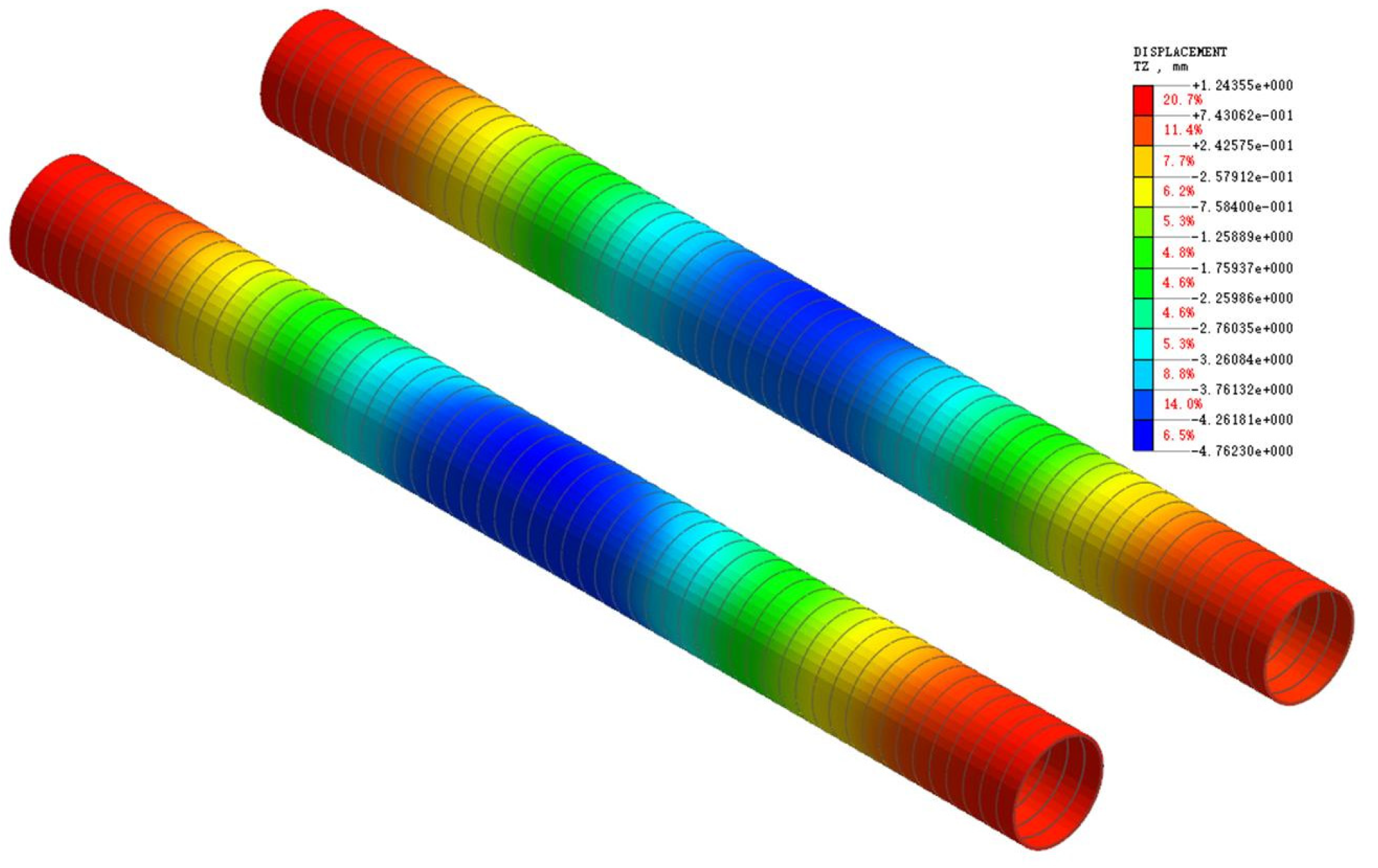
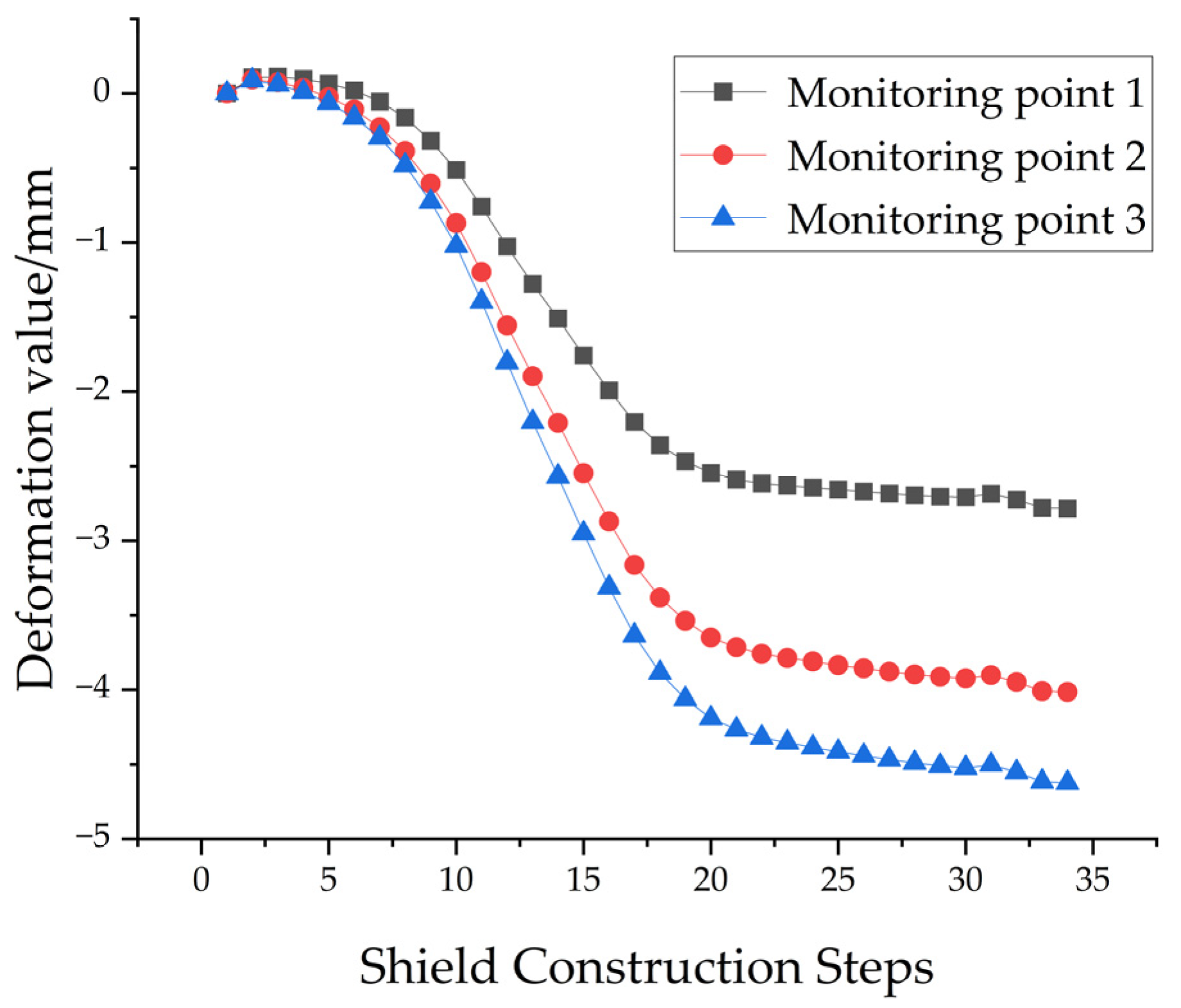
3.4.1. Influence of Two-Lane Shield Underpass on Vertical Settlement of Existing Tunnels

Figure 6 shows the overall vertical deformation distribution of the existing structure after the completion of the new tunnel underpass construction. As can be seen from the figure, the existing tunnel shows a trend of settlement, the maximum settlement occurs in the center of the tunnel, and the size of the settlement deformation gradually decreases from the center of the tunnel to both ends of the tunnel.
By intercepting the deformation data from different locations in the longitudinal direction, we analyzed the influence of the shield tunnel on the existing tunnel structure during the construction process of the near-connection underpass. As shown in the figure, the horizontal coordinate is the distance from the center line of the new double-lane tunnel, and the vertical coordinate is the settlement value of the arch top and arch bottom of the existing tunnel. In Figure 7, (1) to (6) represent the six important construction stages in the shield construction process. For the vault, whether it is the left line or the right line, its settlement trend is generally similar, and ultimately shows a normal distribution; the settlement groove curve is ‘U’ shape, the left and right lines of the maximum settlement are in the center line of the new two-line tunnel position, and the final settlement is 6.07 and 5.85 mm, respectively. The reason for the settlement displacement of the left tunnel arch being slightly larger than that of the right line is that the soil under the existing right line was excavated first, and its additional displacement value is naturally larger, which is also consistent with the actual engineering situation.
At the beginning of the excavation, no significant settlement change was observed at the vault of the existing right line. As the palm face advanced, the settlement trend became more apparent. When the excavation of the new right line reached directly below the existing left line, the settlement displacement at the center of the tunnel of the new left line peaked at 1.23 mm. As the palm face moved further, the displacement accumulated slowly, and by the time excavation reached the lowest point of the existing right line, the settlement reached 1.57 mm. With the excavation of the new right line, the soil above the existing tunnel began to show signs of biased pressure, causing the settlement trough of the existing tunnel to shift from the axis of the new right line toward the axis of the new left line. Simultaneously, the settlement of the vault of the existing right line continued to increase. When the new right line reached directly below the existing tunnel, the settlement increased to 4.00 mm, and by the end of the new tunnel excavation, it reached 5.32 mm.
Additionally, analysis of the existing right line vault settlement data showed that as the palm face reached directly below the existing right line, the additional displacement accumulated gradually, and when excavation reached the lowest point of the existing right line, it amounted to 1.57 mm. The settlement rate was larger at the right line, so the construction process should focus on monitoring the lining deformation at the intersection of the axes of the new and existing tunnels to ensure the smooth progress of construction and the safety of operations.
For the vertical displacement analysis of the existing line’s arch bottom, the deformation trends of the left and right tunnels are largely similar. By the end of the excavation, the arch bottom settlement exhibits a “W” distribution, with the largest settlement values occurring at the intersection of the existing right line and the left and right axes of the new tunnel. The values are 5.17 mm and 5.08 mm, respectively, while the settlement values for the existing left line are 5.12 mm and 5.04 mm. The slightly larger settlement at the intersection of the existing right line and the new tunnel is due to the same factors that contribute to the settlement at the top of the arch.
The settlement trend of the arch bottom of the existing line follows the same pattern as the settlement of the arch top during the excavation of the new tunnel. In this section, we take the existing left line as an example. When the new tunnel first reaches directly underneath the existing right line, the bottom of the arch of the existing left line experiences a slight settlement of 1.05 mm due to the impact of the excavation. As the palm face moves closer directly beneath the existing left line, the settlement rate increases. Once the excavation reaches directly underneath the existing left line, the settlement reaches its first peak of 1.92 mm, and it continues to increase, reaching 4.30 mm by the end of the excavation of the new left line. As the new right tunnel is excavated, the surrounding rock stress is redistributed, and the settlement trough begins to show an asymmetric “W” distribution, with the peak settlement of 2.16 mm occurring at the intersection of the new tunnel and the existing left tunnel. By the end of the excavation, the settlement at the intersection of the new right tunnel reaches 5.12 mm, and the overall settlement trough forms a “W” shape. Further comparative analysis of the settlement values at the arch top and bottom of the existing tunnels, as well as the settlement trough, shows that the final settlement of the arch bottom is larger than that of the arch top. This is because the bottom plate of the existing tunnels is closer to the arch top of the new tunnels. Additionally, the curvature of the elevated arches of the existing tunnels disperses some of the additional stresses, resulting in smaller settlements in areas not directly crossed by the new tunnel.
Figure 8 clearly shows the vertical deformation curves of the monitoring points below the left line of the existing tunnel interval under different shield construction steps by the construction of the new left line. According to Figure 8, the monitoring points of each major section show similar deformation patterns. Before the shield excavation of the left line reaches the monitoring point, the vertical deformation of the existing tunnel shows upward floating; when the shield palm surface is more than 30 m away from the existing tunnel interval, it is in the natural excavation state, and the data of the monitoring section are relatively smooth. When the shield machine of the left and right lines advanced to the bottom of the existing tunnel, the monitoring points showed an obvious vertical settlement trend. To control the settlement of the existing tunnel structure, measures such as secondary grouting and radial grouting reinforcement were taken after the shield excavation was completed. Subsequently, due to the installation of tube sheets and grouting construction, the existing structure appeared to be slightly lifted, but as the shield continued to advance, the existing tunnel settlement occurred again until the shield moved away from the existing line, and the vertical deformation of the structure gradually stabilized.

3.4.2. Analysis of Additional Stresses on Existing Tunnels by Double-Line Shield Penetration

The construction of new tunnels beneath the existing line will cause a redistribution of stress in the surrounding rock of the existing tunnel. This redistribution results in additional deformation of the existing tunnel, along with additional stress, which may lead to cracking of the tunnel’s two-lining structure, track misalignment, and significantly affect the normal operation of the existing line. Therefore, this section extracts the Von Mises stresses in the lining structure of the existing tunnel during key construction stages for analysis, as shown in Table 3.
Table 3 shows that the additional stress generated by the excavation of the new tunnel on the secondary lining of the existing tunnel is entirely tensile. As construction progresses, these tensile stresses continue to increase, ultimately reaching 3164 kN/m2. For the maximum Von Mises stresses, the value rises as shield tunneling progresses, and by the end of the excavation of the new tunnel, the maximum additional Von Mises stress in the existing tunnel reaches approximately 1470 kN/m2 (1.47 MPa). The minimum Von Mises stress decreases gradually as the left tunnel is excavated, then increases slowly during the excavation of the right tunnel. This is due to the increased tensile stress on the secondary lining of the existing tunnel, which intensifies as the excavation of the right lane disturbs the upper strata further.
The secondary lining of the existing tunnel is constructed using C50 concrete, with standard compressive and tensile strengths of 32.40 MPa and 2.64 MPa, respectively. Comparing the additional stress values to the tensile strength, it is evident that the increased stress is still below the standard tensile strength. Therefore, the secondary lining continues to meet the tensile load-bearing requirements. However, during the excavation of the new right-lane tunnel, special attention should be paid to monitoring any potential cracking of the secondary lining to ensure the safety of the tunnel’s operation. Further analysis of the Von Mises stress values at key positions, including the arch top, arch bottom, and both arch waists at the intersection of the existing left and right lines and the centerline of the new left tunnel, shows that the patterns at these positions remain consistent at each construction stage, as depicted in Table 3.
Taking the existing right tunnel as an example, during the excavation of the new tunnel, the overall stress is primarily tensile. At the vault position of the existing right tunnel, the stress value increases with the progress of excavation, ultimately reaching 1619 kN/m2. The stress at the bottom of the arch shows minimal change. The stress at both sides of the arch waist initially decreases, then gradually increases. Therefore, during the construction process, special attention should be given to the secondary lining at the sides of the arch waist and vault to prevent cracking caused by excessive stress.

3.5. Influence of Construction Parameters on the Deformation of Existing Tunnels

The impact of the tunnel’s near-connection and excavation through the existing line is significant. To ensure the safe and stable construction of the new tunnel while allowing the existing line to operate smoothly, it is crucial to analyze the internal and external influencing factors of the shield tunneling process, specifically the shield tunneling pressure and grouting pressure. To ensure data comparability, the method of controlling variables is adopted. Finite element numerical simulations are conducted for the corresponding parameters while keeping other parameters unchanged, using the vertical displacement of the arch bottom as the analysis index.

3.5.1. Influence of Soil Compartment Pressure on the Deformation of Existing Tunnels

To analyze the influence of soil warehouse pressure on the vertical deformation of the existing tunnel in the process of under-passing construction, keeping other parameters unchanged, the soil warehouse pressures of 0.10, 0.20, 0.30, and 0.40 MPa for four working conditions were taken for research. Figure 9 shows the change rule of vertical displacement of the left arch bottom of the existing tunnel under different soil warehouse pressures.
From Figure 9, it can be seen that the change of soil warehouse pressure on the existing line settlement changes in the overall impact is not big; with the grouting pressure from 0.1 MPa to 0.40 MPa, the arch bottom settlement displacement value peak gradually reduces, and the magnitude tends to stabilize. At this time, the shield machine tunneling pressure is less than the static soil pressure of the soil in the face of the palm, the tunneling pressure caused by the increase in the soil disturbances is smaller, and the impact of the soil range is reduced. When the shield machine is not digging into the existing tunnel, the pressure of the earth warehouse has little influence on the existing line, when the palm surface is digging into the existing tunnel directly below, due to the unloading effect caused by the excavation of the soil body makes the existing line sink dramatically; as the shield continues to move forward on the face of the shield palm, the influence of the pressure of the earth warehouse on the existing line becomes smaller. When the shield machine traverses for the second time, the existing line occurs for the second time, but at this time, the amount of settlement is much smaller than the first traverse of the vertical displacement of the existing tunnel.

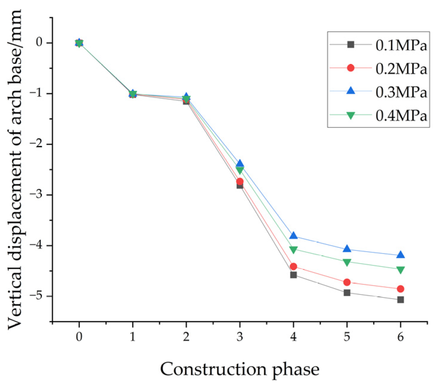
3.5.2. Influence of Grouting Pressure on Deformation of the Existing Tunnels

To analyze the influence of grouting pressure on the vertical deformation of the existing tunnel during the under-passing construction, the other parameters are kept unchanged. Three working conditions with grouting pressures of 0.10, 0.20, 0.30, and 0.40 MPa are studied. Figure 10 illustrates the vertical displacement pattern at the bottom arch of the left line of the existing tunnel under different grouting pressure conditions during the shield tunneling process.
For the left line of the existing tunnel, the settlement trend follows a consistent pattern as the grouting pressure increases. When the grouting pressure is 0.10 MPa, the vertical displacement value of the arch bottom reaches 5.07 mm. In contrast, with a grouting pressure of 0.30 MPa, the maximum vertical displacement of the left line of the existing tunnel is 4.19 mm, while at 0.40 MPa, the displacement increases again. Based on these results, a grouting pressure of 0.30 MPa is considered optimal during the construction process. Additionally, in the early stages of shield construction, before the tunneling surface reaches the crossing area, the influence of grouting pressure on the existing tunnel is minimal. The effect of different grouting pressures on the tunnel’s deformation becomes more pronounced once the shield reaches the existing tunnel’s bottom.

4. Analysis of Settlement Monitoring Results

4.1. On-Site Monitoring

Since the shield tunnel will pass through the existing tunnel during the boring process, it is essential to monitor both the ground surface and tunnel settlement to ensure the safe operation of the existing tunnel throughout construction. The monitoring scope of this project includes the tube sheet and ground surface within a 60 m radius on each side of the centerline of the existing Metro Line 5 tunnel, with a particular focus on the shield area. Surface settlement measurement points are positioned at the shield starting and receiving sections, with one measurement point at each location, and additional points spaced every 100 m along the remaining sections. For the existing tunnel structure, measurement points are placed every 5 m. In the ordinary boring section of the shield interval, the monitoring section spacing follows the design drawings, set at 150 m. Axial monitoring points are spaced every 30 m. The layout of the measurement points is shown in Figure 11.

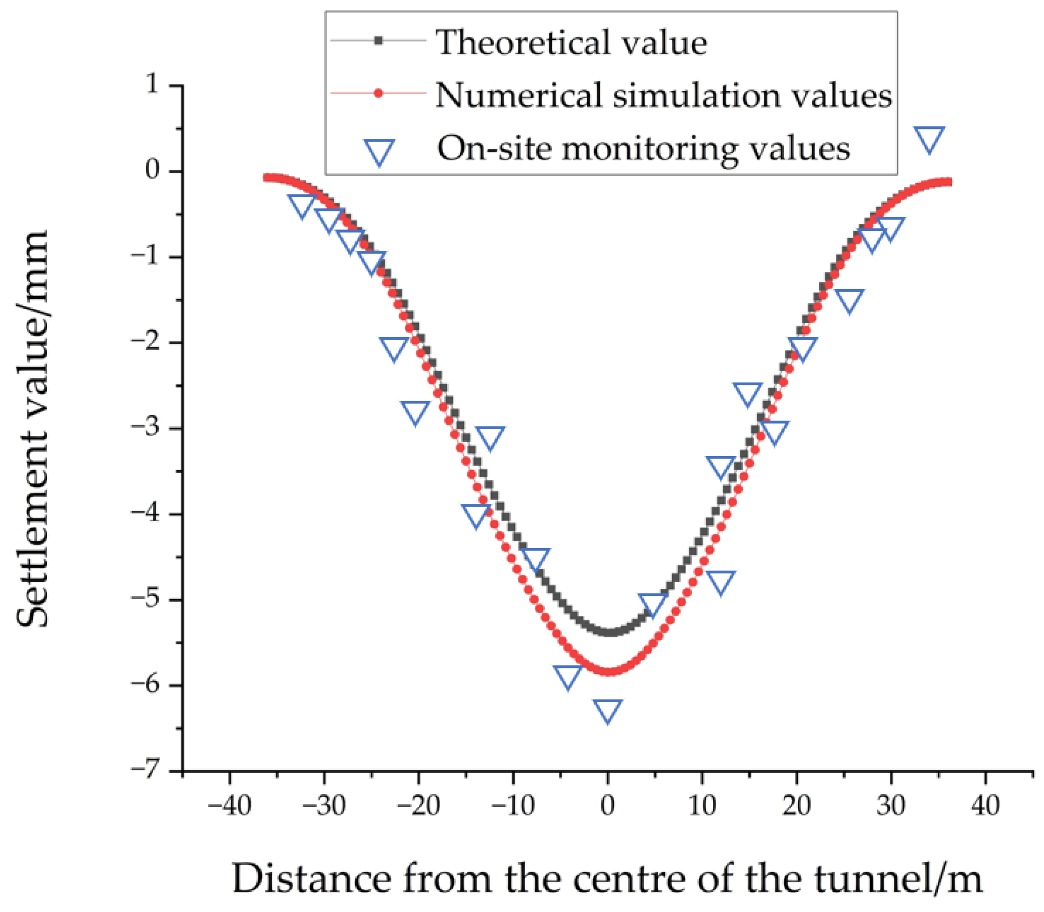
4.2. Theoretical Calculation, Numerical Simulation, and Monitoring Data Comparison

The vertical displacement of the arch on top of the left line of the existing tunnel is selected as an example. The theoretical settlement value is calculated using Equation (7) and compared with the numerical simulation results and on-site monitoring data. The comparison results are shown in Figure 12.
After comparing the settlement values of the shield tunnel obtained from the two methods with the measured data, it is observed that the formula-based calculations yield slightly smaller values than the numerical simulation results. The maximum difference does not exceed 1 mm.
The shape of the curves is similar, and most of the monitoring data on vault settlement falls within the curves. Since the monitoring points are in the shield penetration area, they are inevitably influenced by various construction conditions. The data fluctuations caused by the specific operational environment are unpredictable, leading to some monitoring data exceeding the calculated range. Overall, both the calculation formula and numerical simulation encompass most of the section’s monitoring data, and the predicted curves align with the surface settlement pattern. This makes the methods applicable to the construction of similar working conditions or strata.

5. Conclusions

Through theoretical calculations, numerical simulation of the interval project from Dongfang Road Station to Barracuda Bay Station of Dalian Metro Line 4, and on-site monitoring, the following conclusions are obtained:
(1) By summarizing Peck’s prediction formula for the new two-lane shield tunnel passing beneath the existing tunnel, the surface soil settlement deformation is calculated using the superposition principle, with additional displacement obtained by correcting the width of the settlement tank and the stratum loss rate. The vertical displacement of the existing tunnel is determined using the finite difference method, applying the balanced differential equation of displacement load–tunnel deformation. This method’s algorithm is straightforward, easy to understand, and provides quick, effective guidance for the construction of urban underground projects.
(2) For the existing tunnels, vertical deformation is primarily influenced by the vertical settlement of the arch top, which is smaller than that of the arch bottom. The settlement groove at the arch top follows a typical pattern aligned with the centerline of the new twin tunnels. In contrast, the settlement groove at the arch bottom forms a “W” shape due to the tunnel arch bearing part of the additional stress. The maximum settlement occurs directly beneath the crossing point of the new tunnel and the centerline of the existing tunnel. The final settlement in the existing left line is slightly larger than that of the right line. During construction, particular attention should be given to the impact of the shield tunnel’s first crossing on the existing tunnel.
(3) The secondary lining of the existing tunnel is in the tensile state as a whole, and the resulting additional stress value is 1.47 MPa, which is smaller than the standard tensile value of C50 concrete and meets the load-bearing requirements, but in the part of the arch at the cross position, the stress value increases significantly, and there is the possibility of pulling crack.
(4) The grouting pressure has a large impact on the vertical settlement of the existing line, but the change in the soil chamber pressure has a smaller impact on the settlement of the existing tunnel.
(5) Based on the measured data, the settlement values of the existing tunnels predicted by both theoretical calculation and numerical simulation methods were compared and analyzed. The results demonstrate that the predicted location of the maximum settlement value and the overall settlement trend from both methods are highly consistent, further validating the accuracy and reliability of the theoretical model.
The above-obtained influence law of a double-line shield going through the existing tunnel can provide a reference for similar engineering practices.

Author Contributions

J.L.: Provision of ideas and methods. X.F.: Editing and modification, data processing. Y.Y.: Optimization of image tables and supervision. All authors have read and agreed to the published version of the manuscript.

Funding

The research received financial support from the National Natural Science Foundation of China (Grant No. 51474045).

Institutional Review Board Statement

Not applicable.

Informed Consent Statement

Not applicable.

Data Availability Statement

Some or all data that support the findings of this study are available from the corresponding author upon reasonable request.

Conflicts of Interest

The authors declare no conflicts of interest. The funders had no role in the design of the study; in the collection, analyses, or interpretation of data; in the writing of the manuscript; or in the decision to publish the results.

References

  1. Sagaseta, C. Analysis of undrained soil deformation due to ground loss. Geotechnique 1987, 37, 301–320. [Google Scholar] [CrossRef]
  2. Wei, G.; Zhao, D.G.L.; Qi, Y.J. Research on the calculation method of vertical displacement of existing tunnel caused by similar rectangular shield tunnel tunneling. Tunn. Constr. 2022, 42, 960–966. [Google Scholar]
  3. Gan, X.L.; Yu, J.L.; Gong, X.N. Study on the influence of new double-track tunnel underpass on existing shield tunnel. Chin. J. Rock Mech. Eng. 2019, 39, 3586–3594. [Google Scholar]
  4. Zhang, Z.G.; Chen, J.; Zhu, Z.G. Analysis of longitudinal deformation of existing discontinuous tunnel induced by shield tunneling based on Kerr foundation model. Chin. J. Geotech. Eng. 2019, 45, 2238–2247. [Google Scholar]
  5. Wang, L.X.; Liu, S.J.; Wang, J. Research on settlement deformation of existing tunnel caused by shield tunneling. Chin. Q. Mech. 2019, 45, 855–866. [Google Scholar]
  6. Fan, W.H.; Xie, S.H.; Zhou, F.C. Case study on proximity impact zoning and control measures of new double-track shield tunnel under existing tunnel. Mod. Tunn. Technol. 2019, 60, 43–57. [Google Scholar]
  7. Zhang, Q.F.; Xia, T.; Ding, Z. Displacement influence and construction control of the existing subway tunnel by shield tunneling at a short distance. Rock Soil Mech. 2016, 37, 3561–3568. [Google Scholar]
  8. Si, J.B.; Zhu, Y.H.; Ji, C. Measurement and analysis of vertical deformation caused by rectangular shield tunneling in soft soil. Chin. J. Rock Mech. Eng. 2017, 36, 1551–1559. [Google Scholar]
  9. Gan, X.L.; Yu, J.L.; Gong, X.N. Characteristics and countermeasures of tunnel heave due to large-diameter shield tunneling underneath. J. Perform. Constr. Facil 2020, 34, 04019081. [Google Scholar] [CrossRef]
  10. Lin, Q.T.; Lu, D.C.; Lei, C.M. Model test study on the interaction between shield, pebble stratum, and existing tunnel during underpass construction. J. Beijing Univ. Technol. 2021, 47, 328–337. [Google Scholar]
  11. Zhao, D.G.L.; Wei, G.; Liang, L.J. Model test study on the influence of similar rectangular shield construction on adjacent existing tunnels in sandy soil. Tunn. Constr. 2019, 44, 1000–1011. [Google Scholar]
  12. Liu, Y.; Cao, Y.Z.; Wu, X.L. Model test research on the existing open-cut tunnel under subway shield construction. Chin. J. Railway Sci. 2024, 45, 110–121. [Google Scholar]
  13. Michael, K.; Dimitris, L.; Ioannis, V. Development of a 3D finite element model for shield EPB tunneling. Tunn. Underground Space Technol. 2017, 65, 22–34. [Google Scholar]
  14. Golpasand, M.R.B.; Do, N.A.; Dias, D. Effect of the lateral earth pressure coefficient on settlements during mechanized tunneling. Geomech. Eng. 2018, 16, 643–654. [Google Scholar]
  15. Moosavi, E.; Shirinabadi, R.; Rahimi, E. Numerical modeling of ground movement due to twin tunnel structure of Esfahan subway, Iran. J. Min. Sci. 2018, 53, 663–675. [Google Scholar] [CrossRef]
  16. Wu, X.G.; Yang, S.; Tian, J.K. Analysis of influence parameters of shield proximity construction on existing tunnels and study on proximity zoning. J. Civ. Eng. Manag. 2021, 38, 96–109+114. [Google Scholar]
  17. Zhou, Z.; Zhong, C.P.; Xie, W.D. Study on the influence of normal pressure bulkhead opening in mudstone formation on the deformation of existing tunnel structure. Mod. Tunn. Technol. 2023, 60, 205–212. [Google Scholar]
  18. Liu, B.; Tao, L.G.; Ding, C.G. Prediction and application of ground subsidence induced by double tunnel construction. J. China Univ. Mining Technol. 2006, 3, 356–361. [Google Scholar]
  19. Mair, R.J.; Taylor, R.N.; Bracegirdle, A. Subsurface settlement profiles above tunnels in clays. Géotechnique. 1993, 43, 315–320. [Google Scholar] [CrossRef]
  20. Qi, J.; Wang, Z.J.; Chen, Z.J. Analysis on the width parameter of deep soil settlement trough caused by shield tunnel excavation. Mod. Tunn. Technol. 2019, 61, 29–41. [Google Scholar]
  21. Zhang, Q.; Wu, K.; Cui, S.; Yu, Y.; Zhang, Z.; Zhao, J. Surface settlement induced by subway tunnel construction based on modified peck formula. Geotech. Geol. Eng. 2019, 37, 2823–2835. [Google Scholar] [CrossRef]
  22. Lin, C.G.; Huang, M.S. Deflection of discontinuous underground pipeline in shield tunnel excavation based on Pasternak foundation. Chin. J. Geotech. Eng. 2019, 41, 1200–1207. [Google Scholar]
  23. Zhang, X.Q.; Zhang, M.X.; Li, L. Study on construction disturbance mechanism of multi-line overlapping shield tunnel in short distance crossing. Rock Soil Mech 2017, 38, 1133–1140. [Google Scholar]
Figure 1. Schematic diagram of the calculation model.
Applsci 15 02642 g001
Figure 2. Schematic diagram of ground settlement underneath two-lane shield tunnel.
Applsci 15 02642 g002
Figure 3. Plane diagram of new Line 4 and existing Line 5.
Applsci 15 02642 g003
Figure 4. Geologic profile of underpass interval.
Applsci 15 02642 g004
Figure 5. 3D numerical model.
Applsci 15 02642 g005
Figure 6. Cloud image of sedimentation deformation.
Applsci 15 02642 g006
Figure 7. Settlement of existing tunnels.
Applsci 15 02642 g007
Figure 8. Vertical deformation rule of left line monitoring point.
Applsci 15 02642 g008
Figure 9. Influence curve of tunneling pressure on existing tunnel deformation.
Applsci 15 02642 g009
Figure 10. Influence curve of grouting pressure on deformation of existing tunnels.
Applsci 15 02642 g010
Figure 11. Layout of monitoring sites. (a) Schematic layout of surface measurement points. (b) Schematic diagram of measuring points in the main section of the tunnel.
Applsci 15 02642 g011
Figure 12. Comparison of theoretical calculation, numerical simulation, and field data.
Applsci 15 02642 g012
Table 1. Geotechnical physical and mechanical index parameters.
Name of Soil LayerThickness/mHeaviness/(kN·m−3)Cohesion/(kPa)The Angle of Internal Friction/(°)Modulus of Elasticity/(MPa)Poisson’s Ratio
Plain fill2.517101580.3
Gravel42003612,0000.28
Fully weathered dolomite1022381520,0000.3
Strongly weathered dolomite2022451635,0000.3
Moderately
differentiated dolomite
23.523703050,0000.3
Table 2. Mechanical parameters of structural materials.
Material NameWeight (kN·m−3)Modulus of Elasticity/GPa)Poisson’s Ratio
Shield shell782500.2
Pipe sheet22.5200.3
Grouting24210.25
Table 3. Von Mises stress value in the construction stage.
ConstructionPhase Maximum Von Mises Stress/(kN·m−2)Minimum Von Mises Stress/(kN·m−2)
(1)2468796
(2)32,478691
(3)2774556
(4)2960504
(5)3109480
(6)3164473
Disclaimer/Publisher’s Note: The statements, opinions and data contained in all publications are solely those of the individual author(s) and contributor(s) and not of MDPI and/or the editor(s). MDPI and/or the editor(s) disclaim responsibility for any injury to people or property resulting from any ideas, methods, instructions or products referred to in the content.

