Article

Numerical Study on the Coupled Impact of Periodic Wake and Pulsating Jet on Film Cooling Efficiency on a Flat Wall

1
School of Energy and Power Engineering, University of Shanghai for Science and Technology, Shanghai 200093, China
2
Shanghai Key Laboratory of Multiphase Flow and Heat Transfer in Power Engineering, Shanghai 200093, China
*
Author to whom correspondence should be addressed.
Appl. Sci. 2025, 15(5), 2558; https://doi.org/10.3390/app15052558
Submission received: 10 January 2025 / Revised: 18 February 2025 / Accepted: 22 February 2025 / Published: 27 February 2025

Abstract

:
This paper presents a numerical study investigating the coupled effects of periodic incoming wake and pulsating jets on the film cooling efficiency of a flat wall. The sweeping frequency of the wake is maintained at a constant 10 Hz, while the blowing ratio (M) varies from 0.3 to 1. By adjusting the initial position of the rod, different phase lags are generated to assess the interaction between the incoming wake and the pulsating jet concerning film cooling efficiency. The results reveal that coupling the wake-affected surface with the low-blowing-ratio phase of the pulsating jet can effectively enhance film cooling efficiency at lower blowing ratios. Conversely, at higher blowing ratios, aligning the low-pressure phase of the pulsating jet at the film hole with the high-blowing-ratio jet pulsation results in an improved film cooling effect. Notably, when the phase lag (ψ) is set to zero, the cooling efficiency of the pulsating film reaches its maximum across all blowing ratios, indicating an optimal coupling strategy.

1. Introduction

With the continuous development of gas turbine technology, the turbine inlet temperature has now surpassed 2000 K [1,2], far exceeding the high-temperature tolerance limit of conventional materials. This urgently requires innovation and optimization in turbine blade cooling technologies [3,4,5,6]. Blade cooling, especially film cooling, has become a critical method to ensure the stable operation of turbine blades in high-temperature gas environments. The film cooling, first proposed by Goldstein [7,8,9], is important in this context. Many studies have been conducted to enhance film cooling efficiency, with a focus on geometric parameters of film holes and aerodynamic parameters of the cooling jet. Several experimental and numerical studies [10,11,12] have focused on optimizing the shape and dimensions of film holes, resulting in significant findings. Techniques such as using cavities [13], upstream ramp [14], and embedding film holes [15] into grooves have shown promise in improving film cooling efficiency. Additionally, researchers have explored the impact of parameters such as blowing ratio, mass flow ratio, and mainstream Reynolds number on film cooling efficiency, leading to the identification of optimal parameter combinations. Zhang et al. [16] studied the interaction between endwall channels and blade showerhead cooling flows, finding that the showerhead cooling flow significantly influences the secondary cooling effect on the endwall and the distribution of cooling airflow. Yang et al. [17] experimentally evaluated novel bean-shaped cooling holes for turbine endwalls, revealing that bean-shaped cooling holes provided superior cooling performance, especially in the pressure-side region. Further studies [18] investigated the effect of pulsating flows in endwall channels on film cooling, providing new correlations for predicting cooling performance. Research by Yang et al. [19] showed that increasing the blowing ratio significantly improved film cooling efficiency and enhanced heat transfer distribution. Numerical simulations by Xu et al. [20] demonstrated that the cooling airflow is affected by secondary flows and upstream structures, and adjusting the position and shape of cooling holes can improve cooling effectiveness.
Vargas et al. [21] performed a numerical evaluation of film cooling performance at different Reynolds numbers and blowing ratios, showing that film effectiveness and net heat flux reduction vary with these parameters, and proposed new methods for evaluating film cooling performance. Liu et al. [22] proposed a cooling hole layout strategy based on conjugate temperature gradient lines, studying how different temperature gradient distributions in cooling hole layouts affect endwall cooling performance. The results showed that adjusting the hole layout could achieve a more uniform film coverage and temperature distribution, with the temperature gradient line layout demonstrating significant advantages in cooling performance. Despite these methods effectively improving cooling performance, the use of cooling air still reduces the adequate airflow, lowering the turbine’s thermal efficiency. In high-performance turbine engines, cooling air consumption can result in a thermal efficiency loss of 20% to 25% [23].
Recent research has focused on pulsating jet cooling technology to reduce cooling air consumption. Pulsating jets reduce the amount of cooling air used and significantly enhance film cooling efficiency [24,25,26,27]. The complex flow phenomena inside gas turbines, including periodic wakes, turbulence, and vortices, profoundly affect film cooling performance [28,29,30]. Therefore, a deeper understanding of how these factors impact film cooling performance is crucial for optimizing turbine cooling system design, thereby improving thermal efficiency and reliability.
Experiments conducted by Sultan et al. [31] using a loudspeaker as a pulsation inducer in flat film cooling have indicated that cooling jet pulsation can impact the film cooling efficiency. Burdet and Abhari [32] employed numerical simulation to demonstrate that a high-frequency pulsating jet exhibits higher cooling efficiency, unlike low- to medium-frequency cooling jet pulsation. In the operational environment of film cooling, the unsteady flow inside gas turbines causes the shedding wake of upstream blades to periodically affect downstream blades, thereby impacting film cooling efficiency [33,34]. Experimental studies by Chen et al. [35] in a low-speed wind tunnel have revealed that the influence of the mass flux ratio on the film cooling effectiveness diminishes under high turbulence intensity and unsteady wake conditions across many areas of the blade surface, and that the film cooling effectiveness decreases as the wake Strouhal number increases.
Thus, optimizing film cooling performance under the combined effects of pulsating jets and wakes has become a key challenge in current research. For instance, Abadi et al. [36] studied the impact of pulsating injection and mainstream attack angle on film cooling performance through experimental and numerical simulations, finding that increasing the attack angle and pulsation frequency significantly improves average film cooling effectiveness. Zhao et al. [37] explored the effects of vortex generators and pulsation on compound-angle film cooling, showing that pulsation can enhance cooling performance under specific conditions. Li et al. [38] found that combining impingement and film cooling technologies significantly improves overall blade cooling efficiency, with pulsating jets playing a critical role in enhancing the cooling effect. Wang et al. [39] conducted studies on the influence of similar flow conditions on film cooling performance, providing additional references for pulsating jet cooling technology research.
Although significant progress has been made in film cooling technology, many challenges remain due to the complex interaction mechanisms among various factors. The interplay between pulsating jets, wakes, and other flow phenomena has not yet been fully understood. Optimizing the film cooling structure under various operational conditions to further enhance cooling efficiency remains an ongoing challenge. This study aims to investigate the film-cooling characteristics of pulsating jets under wake disturbances through numerical simulations and to explore the impact of wake interactions on film-cooling effectiveness in gas turbines, providing theoretical support for optimizing film-cooling technologies.
In this study, we propose that the integration of periodic wake patterns with a pulsating jet may enhance the efficiency of film cooling. The effectiveness of this integration is anticipated to depend on the blowing ratio and the phase lag. We will rigorously evaluate this hypothesis through extensive numerical simulations and a thorough analysis of the resulting data.

2. Numerical Methods

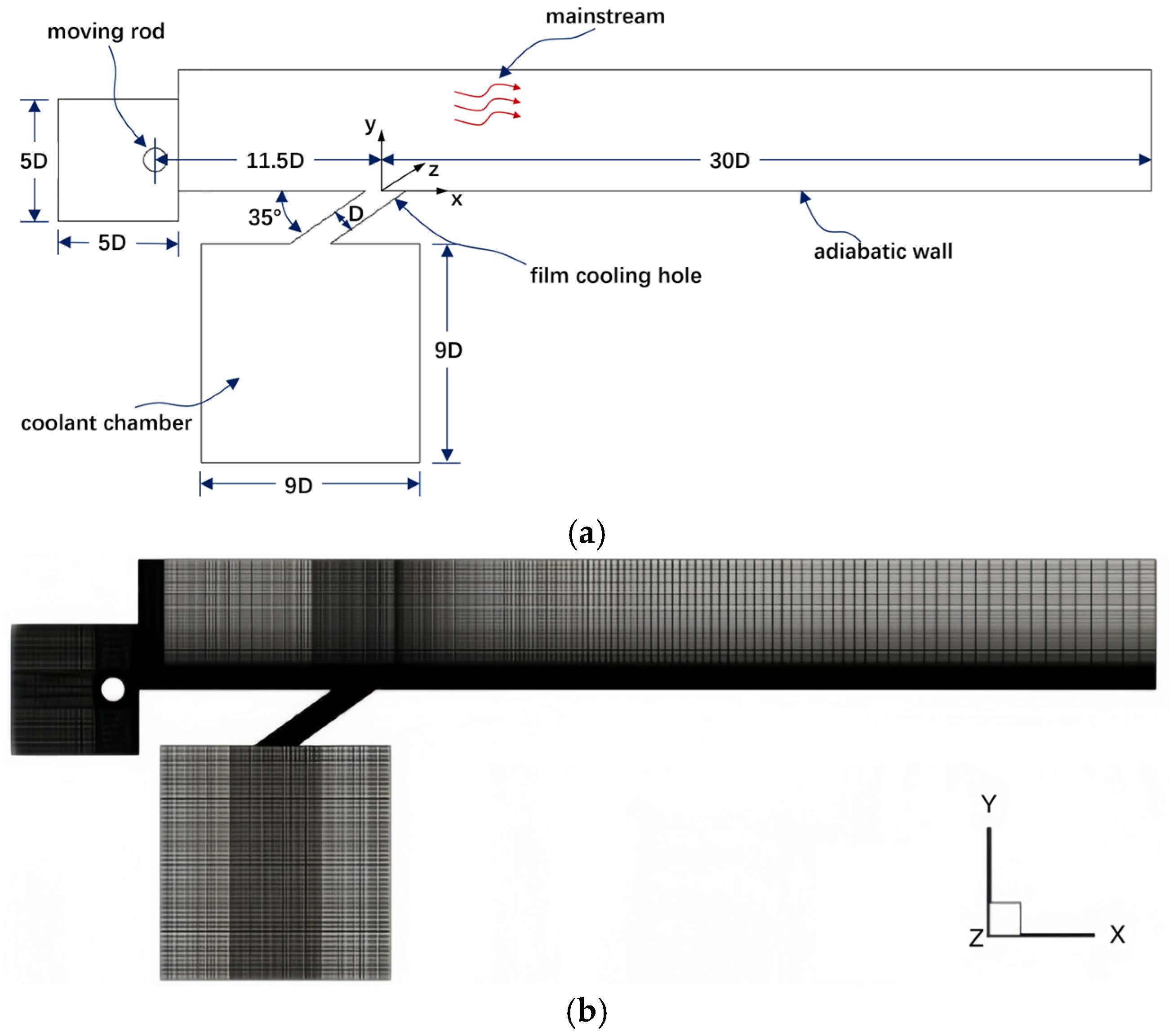
2.1. Numerical Setup

The computational domain and grid are shown in Figure 1. A cylindrical rod with the same diameter D of the film cooling hole is used as a wake generator, and it is placed at 11.5D upstream of the film cooling hole. The computational study employs a structured hexahedral mesh, which facilitates enhanced control over grid quality and accurately represents the intricate flow features present within the computational domain. The grid configuration comprises approximately two million cells, with a more concentrated distribution in regions adjacent to the film cooling hole, the wake generator, and the plate surface. This arrangement is designed to capture flow details in these critical areas effectively. The mainstream fluid temperature is established at 273 K, and its velocity is set at 8 m/s, while the coolant jet entering the system is maintained at 300 K. More details about the experimental setting refer to Coulthard et al. [40].
The sweeping frequency of the rod is kept constant at 10 Hz, and the blowing ratio M is set at 0.3, 0.5, and 1. By adjusting the starting location of the rod, different phase lags are generated to evaluate the coupled effect of the incoming wake and pulsating jet on film cooling efficiency, as shown in Figure 2. Four different phases, i.e., 0, 0.25 T, 0.5 T, and 0.75 T, are selected for the present study.

2.2. Parameter Definition

The blowing ratio M is defined as:
M = ρ c V c ρ V
where ρ c and ρ are the jet and main stream densities and V c and V are the cold air velocity at the exit of the air film hole and mainstream velocity, respectively.
The adiabatic film cooling efficiency η is defined as below, and the averaged film cooling efficiency η ¯ is obtained by surface averaging:
η = T a w T T j e t T
where T a w is the adiabatic wall surface temperature, T j e t is the jet temperature, and T is the main flow temperature.

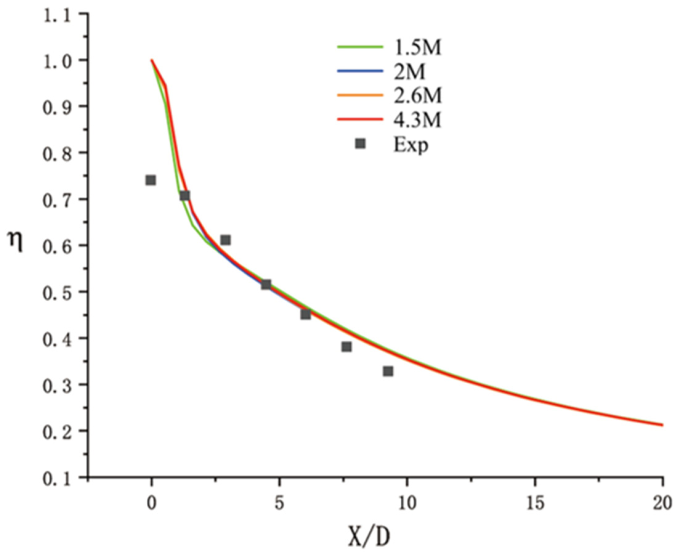
2.3. Grid Independence Study

To conduct the grid independence analysis, four sets of grids with varying sizes were chosen, each comprising approximately 1.5 million, 2 million, 2.6 million, and 4.3 million grid cells. The results of film cooling effectiveness of these grid sets along the centerline are presented in Figure 3. The results reveal discernible discrepancies at the cooling hole outlets with increasing grid numbers. Notably, upon reaching two million grids or more, no consequential variations in the calculated outcomes are observed. Thus, the grid set comprising approximately two million grids is selected for subsequent numerical simulations.

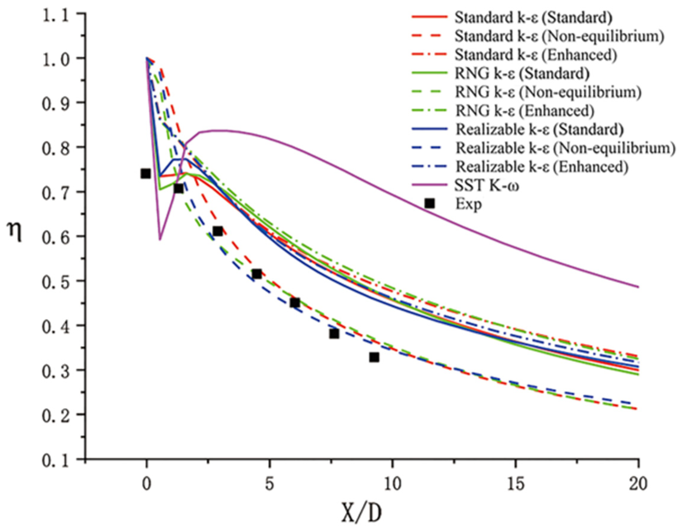
2.4. Turbulence Model Independence Study

Four turbulence models (i.e., Standard k-ε, RNG k-ε, Realizable k-ε, and SST-ω) and three near-wall functions (i.e., standard wall functions, non-equilibrium wall functions, and enhanced wall treatment) are selected for comparison with the experimental results [20]. The resultant film cooling effectiveness values are given in Figure 4. The RNG k-ε turbulence model has been selected due to its superior performance in simulating turbulent flows characterized by complex vortical structures. This model is particularly effective in capturing the impacts of small-scale turbulence, which is critical for accurately predicting the flow and heat transfer characteristics associated with film cooling applications. Furthermore, the non-equilibrium wall function enhances the accuracy of near-wall flow predictions, particularly in regions where the coolant jet interacts with the surface of the plate. This methodological combination has proven effective in a previous study [3] focused on similar flow phenomena. The RNG k-ε turbulence model with non-equilibrium wall function shows the best performance and is chosen for numerical simulations in this paper.

3. Results and Discussion

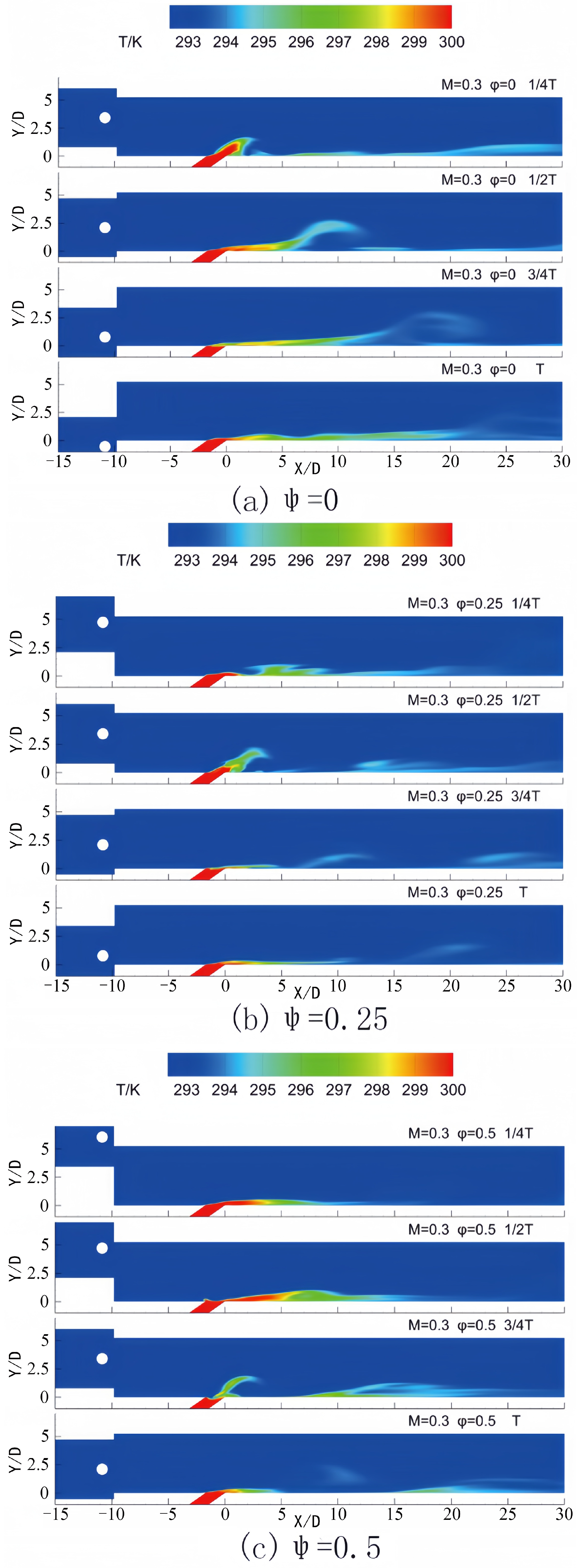
3.1. Blowing Ratio M = 0.3

Figure 5 and Figure 6 illustrate the contours of temperature and vorticity during a single period for varying phase lags between the incoming wake and the pulsating jet in the central plane Z = 0 at a blowing ratio of M = 0.3. The figure demonstrates that after the airflow sweeps over the plate surface in the wake region, the boundary layer separates and progresses downstream due to the reverse pressure gradient. The coolant jet exited from the film hole exhibits a notable lift, with the lift distance extending approximately 10D along the X direction. When the phase lag between the wake and the pulsating jet is equal to 0, as depicted in Figure 5a and Figure 6a, the lift at the film hole is observed at 1/4 T of the cycle. At this point, the pulsating jet is situated near the maximum value of the cycle. As illustrated in Figure 6a, the lift-produced coolant jet leads to insufficient coverage of the flat plate surface by the jet film. Consequently, the uncovered area on the flat plate moves downstream in conjunction with the lift area of the cooling film. At time T, when the wake traverses the surface of the flat plate, the lift area is positioned at 15D, resulting in an enhanced coverage effect of the cold air jet on the plate surface. When the phase difference between the wake and the pulsating jet is 0.25, Figure 5b and Figure 6b indicate that the wake sweeps over the flat plate at 1/4 T. During this phase, the jet blowing ratio at the outlet of the film hole reaches its maximum, though the film coverage at the film hole remains inadequate. The jet lift at the film hole occurs at 1/2 T of the cycle, at which point the jet blowing ratio is in a phase of decline, leading to a diminished coverage effect of the jet on the plate surface in subsequent cycles. When the phase difference between the wake and the pulsating jet is 0.5, Figure 5c and Figure 6c reveal that the wake sweeps over the flat surface at 1/2 T, where the jet blowing ratio continues to decrease. Within the wake’s sweeping range, the jet blowing ratio remains relatively high, thereby producing significant film lift. At 3/4 T, jet lift is observed at the film hole, and the jet blowing ratio reaches its lowest value within the cycle, resulting in improved mainstream coverage at the film hole. Lastly, when the phase difference between the wake and the pulsating jet is 0.75, Figure 5d and Figure 6d illustrate that the wake sweeps over the flat plate at 3/4 T. During this period, the jet blowing ratio remains low, leading to minimal coverage of the cold air jet on the surface of the flat plate behind the film hole when the jet lift occurs at the subsequent cycle time T.
Figure 7 presents the instantaneous temperature distribution on the plate surface at various time intervals under the operating condition of M = 0.3. Following the wake’s passage, the lifting area generated by boundary layer separation extends to the film hole, intensifying the jet’s departure from the plate surface and propelling it downstream. During this phase, the coolant jet demonstrates a limited protective effect on the plate surface. The coolant jet reestablishes coverage over the plate surface upon traversing the lifting area. The jet assumes a critical cooling role throughout this interval during the subsequent wake sweeping across the plate. The duration of the exit of the jet lifting area of the film hole to the arrival of the subsequent wake at the plate surface is approximately 0.25 T. When the phase lag between the wake and the pulsating jet is zero, this interval corresponds to the b–c stage of the jet, characterized by the highest flow rate and effective coverage over the plate surface. Conversely, at a phase lag of 0.25, the interval corresponds to the c-d stage, during which the jet flow rate descends below the average value. In this context, the elevated flow rate stage precedes the jet lift, disrupting the favorable film that had formed earlier, significantly compromising the cooling effect. At a phase lag of ψ = 0.5, the lifted jet is in the d–e stage. During this stage, the blowing ratio increases from its minimum value within the cycle yet remains below the average, leading to inadequate coverage by the end of this interval. When the phase lag reaches 0.75, the lifted jet occupies the a–b stage. At this juncture, the jet blowing ratio increases from the average value, resulting in a more effective film coverage.
The changes in turbulence and vorticity represented in these figures are primarily attributable to the interaction among the wake, the pulsating jet, and the separation of the boundary layer. As the wake traverses the plate, it generates a reverse pressure gradient that induces boundary layer separation. This separation leads to an increase in flow disorder, consequently elevating vorticity levels. The separated flow subsequently interacts with the pulsating jet. In the context of turbulence, at a low blowing ratio of M = 0.3, the flow velocity remains comparatively low, enabling viscous forces to exert a significant influence. The periodic motion of the wake, coupled with the pulsation of the jet, destabilizes the flow. In regions where the wake and jet interact, the intensity of turbulence is heightened due to improved mixing among fluids with differing velocities. These modifications in turbulence and vorticity have substantial implications for film cooling efficiency. Increased vorticity may enhance or diminish this efficiency; if it facilitates improved coolant coverage across the plate’s surface, the overall efficiency will be elevated. In contrast, efficiency may decline if it causes the coolant to mix and dissipate too rapidly. While turbulence typically enhances heat transfer and is advantageous for cooling, excessive turbulence may disrupt the film, thus impairing the cooling effect. Therefore, thoroughly comprehending these phenomena is crucial for optimizing the film cooling system. This analysis is further supported by the data shown in Figure 8.

3.2. Blowing Ratio M = 0.5

Figure 9 and Figure 10 present the contours of vorticity and temperature for the wake and pulsating jet at four distinct time intervals within a single cycle, while employing a blowing ratio of M = 0.5. Before analyzing the results at a blowing ratio of M = 0.5 in detail, briefly discussing the differences between Figure 6 and Figure 9 is helpful. In Figure 6 (M = 0.3), the coolant jet has a relatively longer lift distance along the X-direction. However, in Figure 9 (M = 0.5), the jet detaches from the wall behind the film hole and re-attaches to the plate surface at a closer distance due to the higher blowing ratio. Another notable difference is the overall flow pattern influenced by the wake and the jet. At M = 0.3, the wake-sweeping effect dominates the flow field to a greater extent because of the lower blowing ratio.
In contrast, at M = 0.5, the stronger jet dynamics resulting from the increased blowing ratio play a more significant role. This leads to a different interaction mechanism between the jet and the wake, which is clearly shown in the vorticity and temperature contours of Figure 9 and Figure 10 compared to Figure 6. These differences are essential for understanding how the blowing ratio affects the film cooling efficiency and the flow-heat transfer characteristics. The observations indicate that the jet initiates lift at the film hole at 1/4 T of the cycle. At this juncture, the blowing ratio of the pulsating jet approaches its maximum value for the cycle. An increase in the blowing ratio results in a more pronounced lifting effect of the coolant jet compared to the scenario with M = 0.3. The jet detaches from the wall behind the film hole and re-establishes coverage on the plate surface only after a distance of 5D. During the b–c stage, the blowing ratio gradually reduces from its peak following the lifting phase, causing the jet to adhere more closely to the plate surface. Before reaching time T, when the wake traverses the plate surface, the jet’s blowing ratio falls within the cycle’s lower range, providing an effective cooling mechanism for the plate.
When the phase lag between the wake and the pulsating jet is 0.25, the jet attains lift at the film hole at 1/2 T of the period. Although the blowing ratio is declining at this stage, it remains above the average level. In subsequent periods, the blowing ratio decreases, enhancing the coverage effect on the plate surface. At 1/4 T, the wake’s sweep over the flat plate ensures effective film coverage during this phase. In scenarios where the phase lag equals 0.5, the jet lift occurs at the film hole at 3/4 T, coinciding with the lowest blowing ratio observed within the cycle. This results in diminished coverage around the filmhole on the plate surface. However, during the interval when the jet is anticipated to be close to the plate surface, the lift induced by the wake moves away from the surface, thereby reducing the overall cooling effect of the cooling film throughout the cycle. At 1/2 T, the wake sweeps across the flat plate, generating a relatively substantial blowing effect; despite this, the film lift during this phase is inferior to that observed during the lower blowing ratio stage. When the phase lag is 0.75, the jet’s lifting phase occurs before time T, and the lift generated by the wake remains within the lower blowing ratio range. The wake crosses the flat plate at 3/4 T, during which the blowing ratio of the jet is approximately at its average value.
The instantaneous temperature contours presented at various time intervals in Figure 11 provide valuable insights regarding the effects of a blowing ratio (M) of 0.5. When the phase lag between the wake and the pulsating jet is equal to zero, the area where the jet lifts transitions away from the film hole and reaches the plate surface during the b–c stage of the jet cycle. At this stage, the jet flow rate is elevated, and the lifting height is considerable, adversely affecting the film coverage on the plate surface. At a phase lag of 0.25, the jet enters the c–d stage, during which the blowing ratio falls below the average value. This reduction enhances the effectiveness of the film coverage. As the blowing ratio increases, the stability of the film improves, resulting in diminished damage to the front film structure caused by the jet lifting. When the phase lag (ψ) reaches 0.5, the lifted jet is placed within the d-e stage. In this interval, the blowing ratio increases from its minimum value within the cycle, yet it remains below average, contributing to improved film coverage. In the case of a phase lag of 0.75, the lifted jet is observed in the a–b stage. During this phase, the blowing ratio ascends from the average value, leading to a gradual increase in jet height, consequently reducing the film coverage. These findings are consistent with the spanwise average time-averaged film efficiency related to each phase lag, as illustrated in Figure 12.

3.3. Blowing Ratio M = 1.0

Figure 13 illustrates the temperature contours during a single period for varying phase lags between the incoming wake and the pulsating jet in the central plane Z = 0. The velocity of the pulsating jet at the orifice varies over one period, reaching maximum velocity at 1/4 T and minimum velocity at 3/4 T. In Figure 13a, it is evident that the cooling jet, upon ejection from the orifice, ascends from the bottom wall due to its high velocity. However, upon interaction with the incoming wake, the elevated cooling jet is compelled to reattach to the wall at x/D = 5–15, affording cooling protection for the bottom wall. Subsequently, as the jet velocity diminishes and continues to interplay with the pulsating jet, the adhesion of the cooling jet to the wall is enhanced, resulting in an expanded cooling coverage. The combined impact of the wake and jet is subject to variation based on diverse phase lags between the incoming wake and the pulsating jet. Figure 13b demonstrates superior cooling jet coverage compared to Figure 13a at the equivalent instant within a single period.
In Figure 13c, with a phase lag of 0.5, at 1/4 T, the cooling jet, upon ejection from the orifice, demonstrates an initial upward movement analogous to the previous cases. However, due to the specific phase of the pulsating jet and the influence of the wake, the cooling jet begins to be affected by the encroaching wake. As time progresses to 3/4 T, the velocity of the jet notably decreases, and the effect of the wake becomes increasingly pronounced. The wake constrains the cooling jet to reattach to the wall at shorter distances when compared to Figure 13a,b, leading to a cooling coverage that is more concentrated in proximity to the film hole.
In Figure 13d, where the phase lag is 0.75, the cooling jet similarly shows an upward trend at 1/4 T. However, as the wake traverses the plate at 3/4 T, its influence on the jet becomes substantial. The wake not only compels the jet to reattach to the wall but also modifies the shape and extent of the film coverage. In comparison to other phase-lag cases, the film coverage illustrated in Figure 13d exhibits a distinct distribution pattern. It reveals a more dispersed cooling area behind the film hole at both 3/4 T and T, which may be attributable to the combined effects of variations in the jet velocity and the robust perturbation induced by the wake. These distinctions between Figure 13c,d underscore how the phase lag between the incoming wake and the pulsating jet influences the performance of the cooling jet and the resulting film cooling efficiency at a blowing ratio of M = 1.0.
The interaction between the incoming wake and the pulsating jet is illustrated in Figure 14, where vorticity contours are presented. It is evident that as the passing wake approaches the ejected cooling flow, it induces a bending effect on the cooling jet towards the bottom wall. At t = 1/4 T, illustrated in Figure 13a, the preceding wake has just passed the bottom wall while the subsequent wake is still distant, exerting minimal influence on the cooling jet. Consequently, the incoming wake attaches to the bottom wall anterior to the cooling jet, as depicted in Figure 14b,c, thereby mitigating the upward movement of the cooling jet and ensuring effective coverage of the cooling protection. Consequently, the conjoined effect of the incoming wake and the pulsating jet significantly impacts the coverage of the cooling jet. The conjoined effect of the wake and the pulsating jet can be discerned from the temperature contours in Figure 15.
In Figure 15a at 1/4 T, inadequate cooling is observed in the region directly behind the film hole due to the upward movement of the cooling jet. However, at subsequent time intervals (3/4 T or T), enhanced cooling performance is evident immediately behind the hole, attributed to the influence of the incoming wake, which directs the cooling jet to adhere to the bottom wall. Similarly, in Figure 15b–d, insufficient cooling is observed in the regions behind the hole. Furthermore, a decrease in the exit velocity of the pulsating jet results in reduced coverage and intensity of the cooling protection.
Figure 16 illustrates the streamwise distribution of the time-averaged film cooling efficiency. It is evident that the immediate region behind the film hole (denoted as 0) experiences suboptimal lower wall cooling due to the uplifting effect of the cooling jet. The phase delay between the incoming wake and the pulsating jet notably influences film cooling effectiveness. Our study reveals that a decreased phase delay, as defined herein, results in higher cooling efficiency for the pulsating jet compared to steady cooling. Conversely, the cooling efficiency diminishes as the phase delay increases.
A detailed comparison of the results in Figure 8, Figure 12 and Figure 16 reveals the relationship between the time-mean span averaged film cooling efficiency and varying blowing ratios. At a low blowing ratio of M = 0.3, the relationship between wake-jet coupling and cooling efficiency is notably intricate, as significant phase lag influences the coverage of the coolant jet. When the blowing ratio increases to M = 0.5, the effect of the plane’s induced lift due to the wake becomes more prominent, thereby impacting cooling efficiency through the interaction between jet lift and fluctuations in the blowing ratio. At M = 1.0, the elevated blowing ratio results in a substantial jet lift, with the influence of the wake primarily observed at the leading and trailing edges of the elevated region. Although a zero-phase lag consistently produces the highest cooling efficiency across all blowing ratios, the underlying mechanisms and the extent of the efficiency changes depend on the specific blowing ratios employed.

4. Conclusions

In this study, a computational analysis was carried out utilizing a flat plate model to investigate the phenomena of jet pulsation and periodic wake behavior in film cooling applications. Based on the numerical simulation results across three different blowing ratios (M = 0.3, 0.5, and 1.0) and various phase lags, it was confirmed that the coupling of periodic wake and pulsating jet significantly impacts film cooling efficiency. When the blowing ratio was low (M = 0.3), the film cooling efficiency could be improved by coupling the wake-affected surface with the low-blowing ratio stage of the pulsating jet. At higher blowing ratios (M = 1.0), the film cooling effect was optimized by integrating the pulsating low-pressure phase at the film hole with the jet pulsating high-blowing ratio. Moreover, it was found that the cooling efficiency of the pulsating film reached its peak across all blowing ratios when the phase difference was equal to zero, which indicates that the optimal coupling strategy depends on the blowing ratio and phase lag. Thus, the hypothesis was generally accepted. The primary conclusions drawn from the research are as follows:
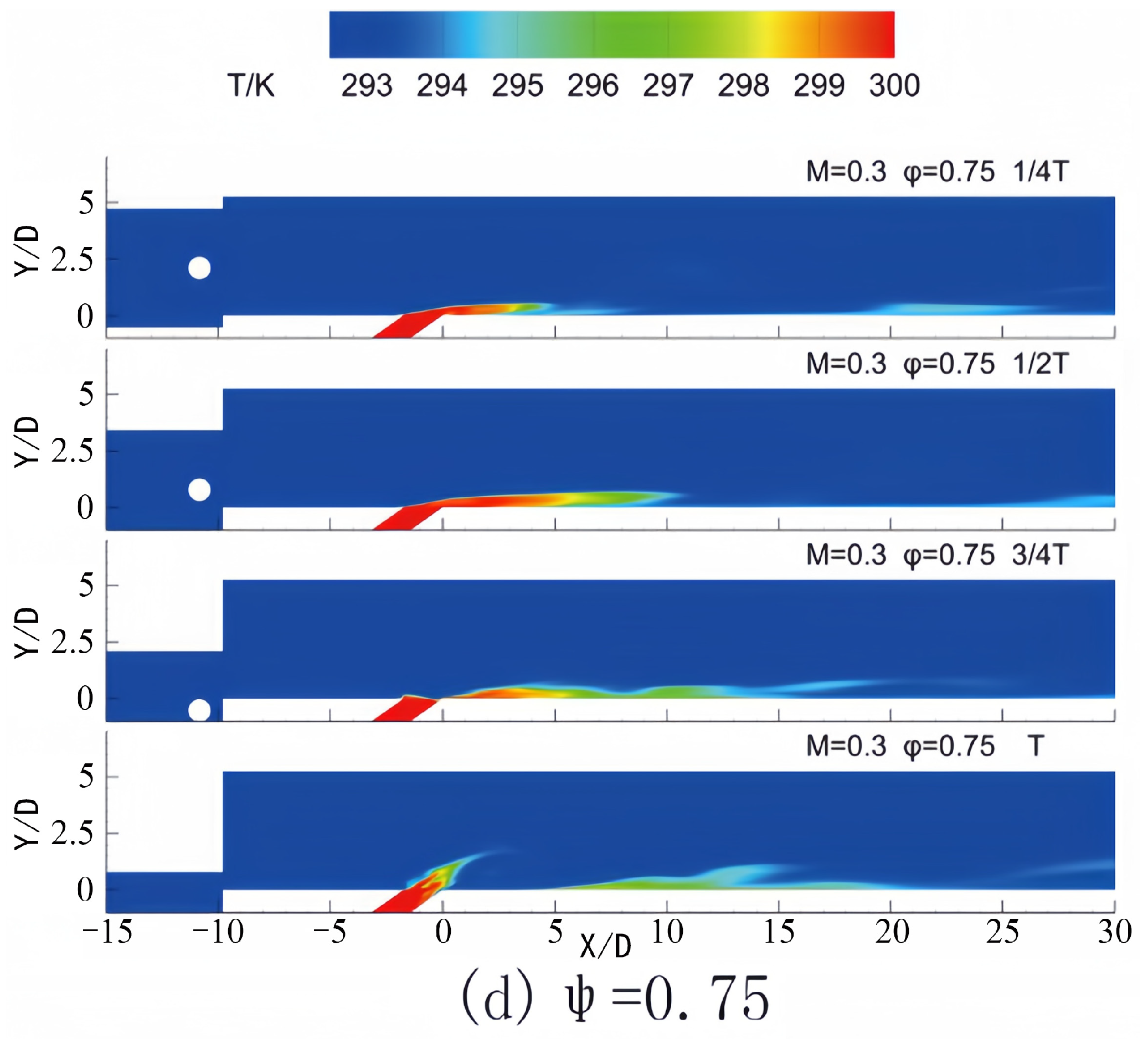
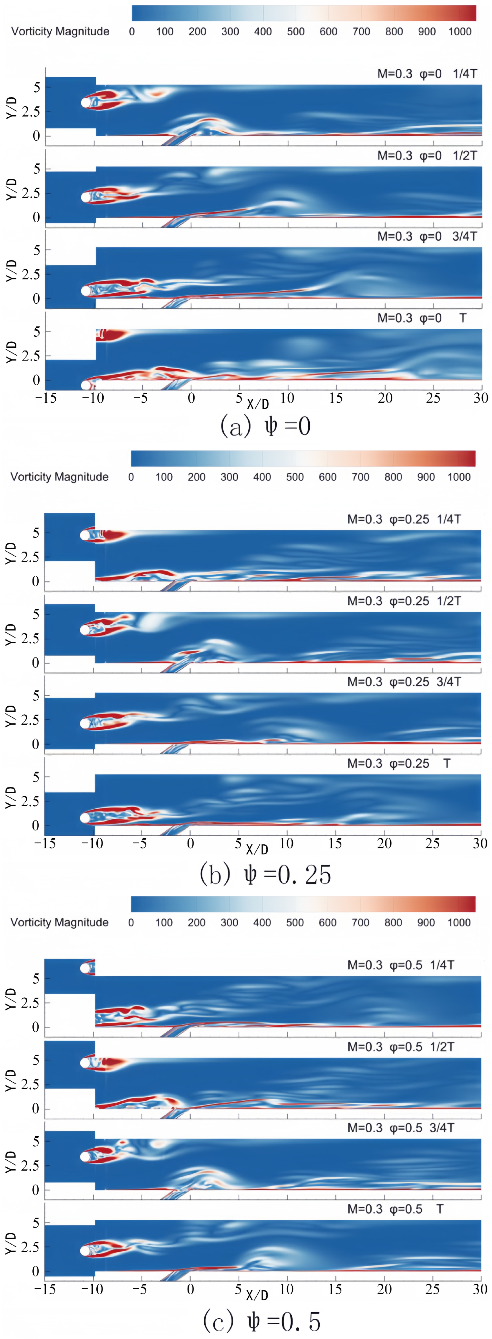
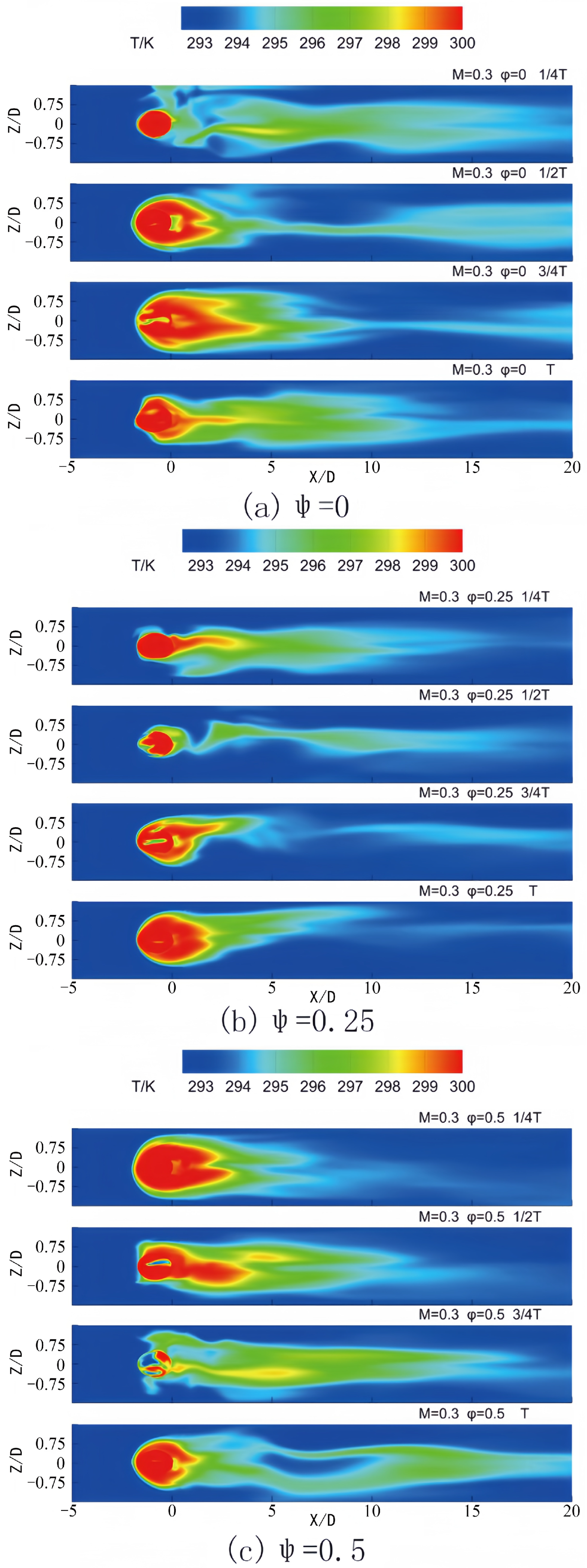
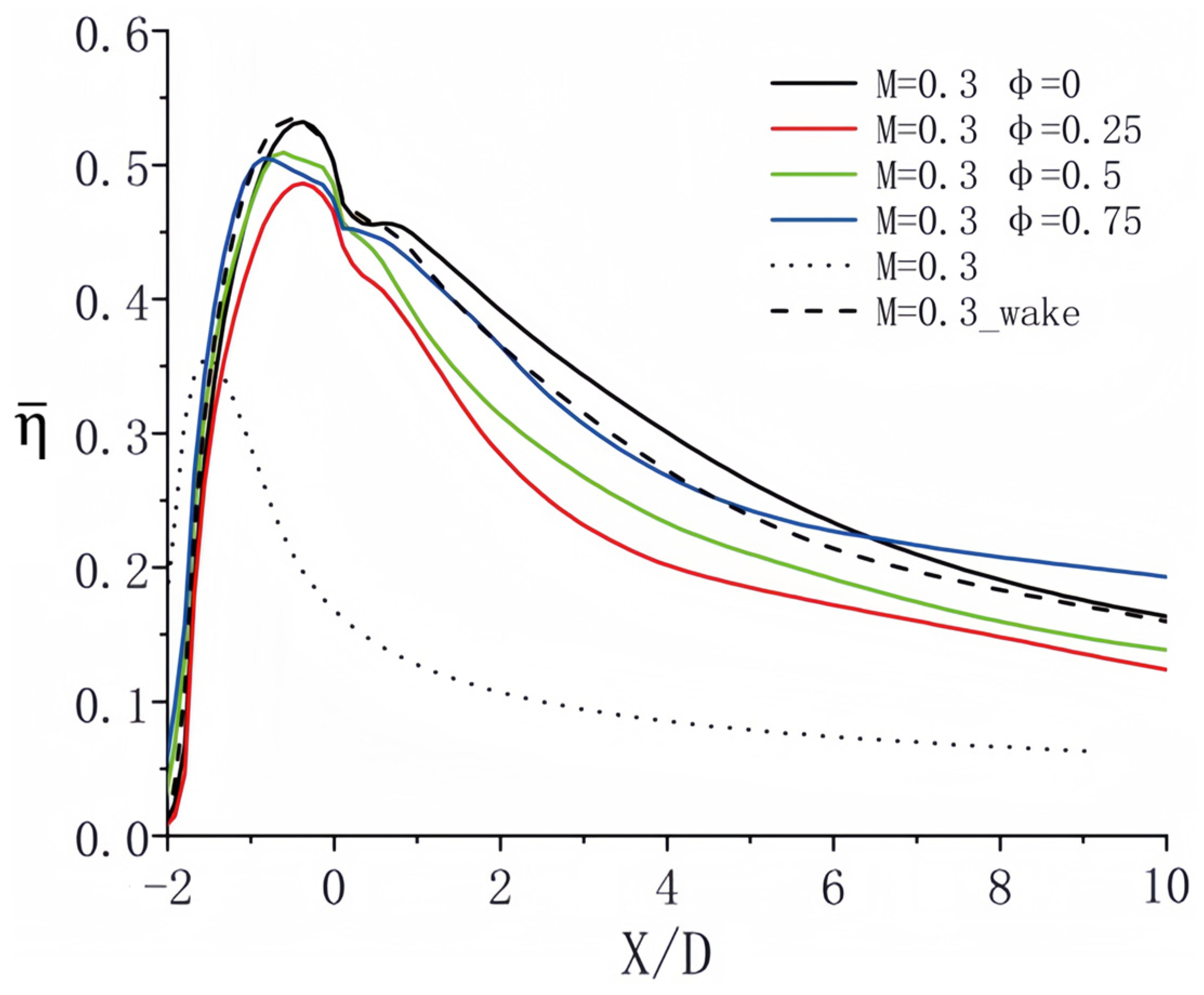
  • For a blowing ratio of M = 0.3, the variations in the blowing ratio are minimal, resulting in the predominance of the wake sweeping process. Therefore, it was essential to couple the surface affected by the wake with the low blowing ratio stage of the pulsating jet. Moreover, due to the low overall blowing ratio, the film structure was susceptible to being lifted and damaged by the wake, adversely affecting the cooling efficiency.
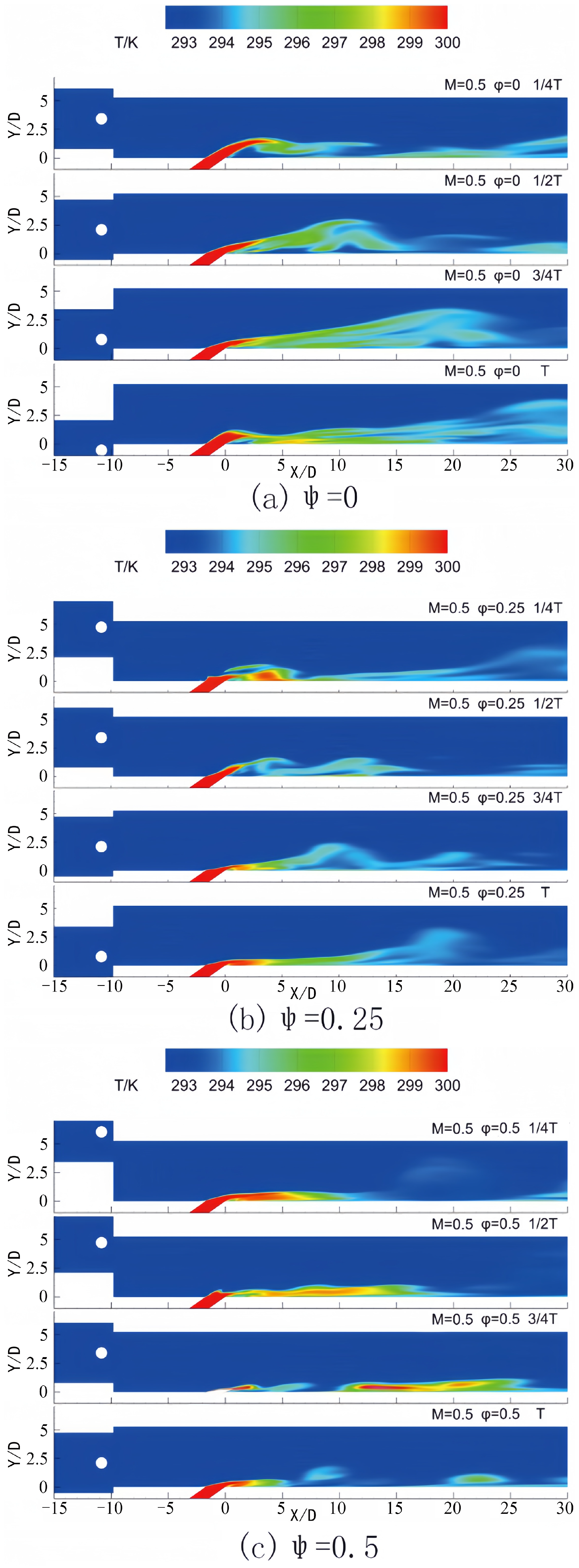
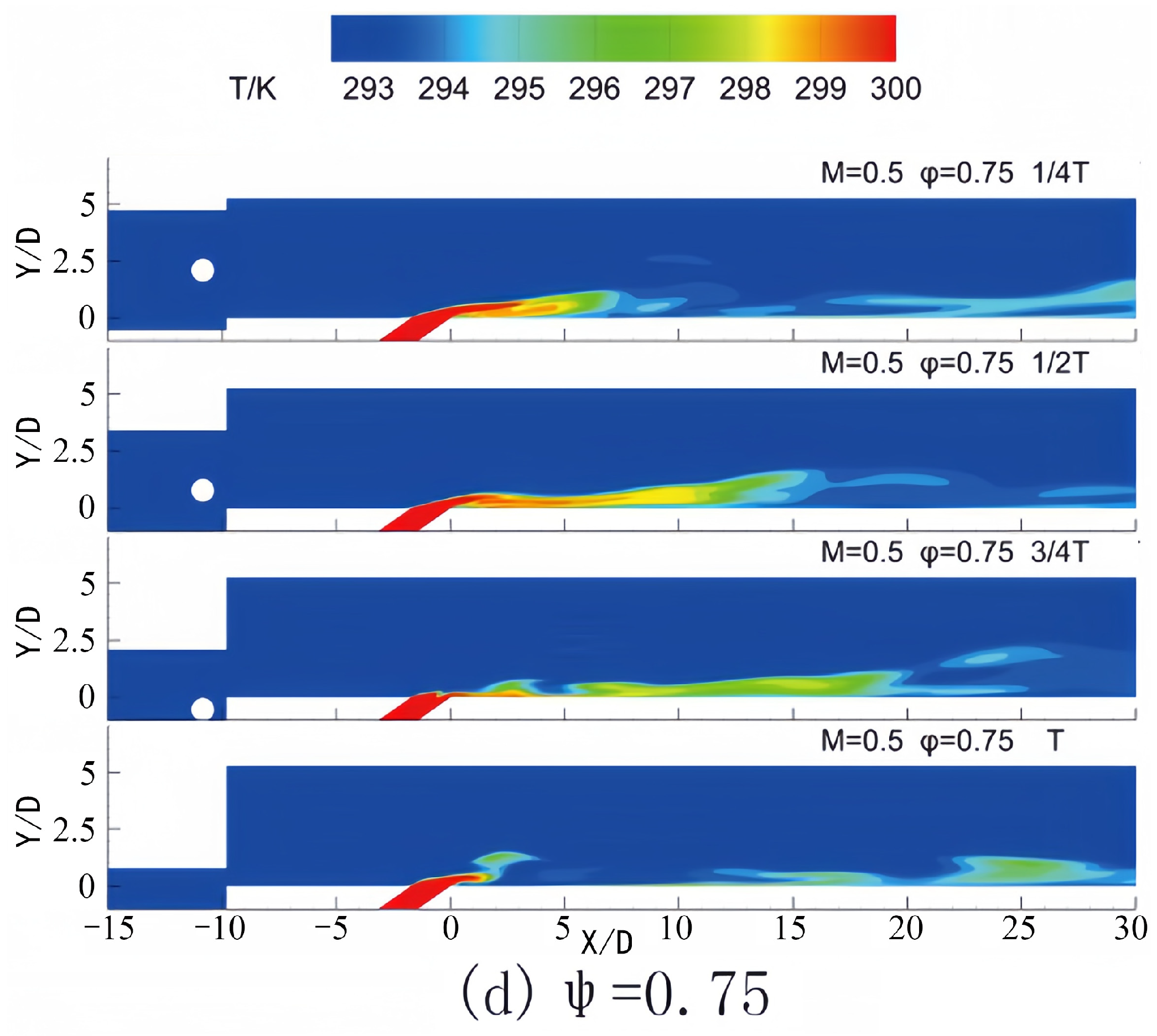
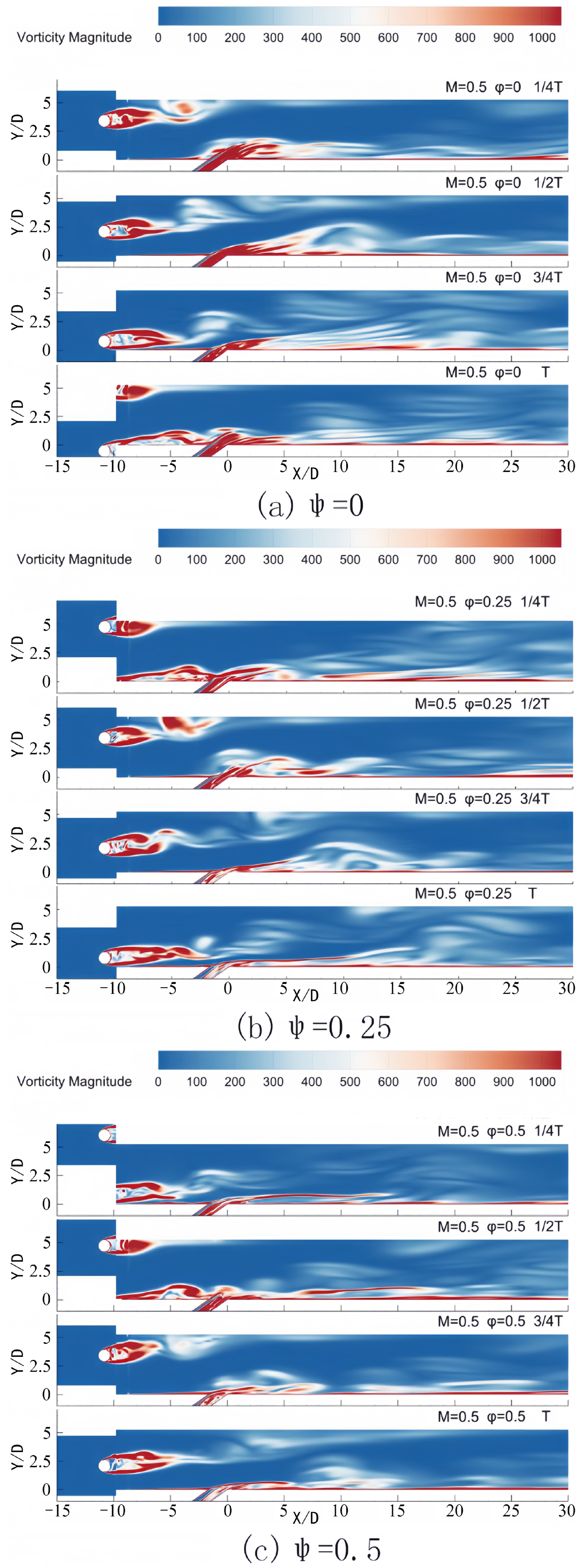
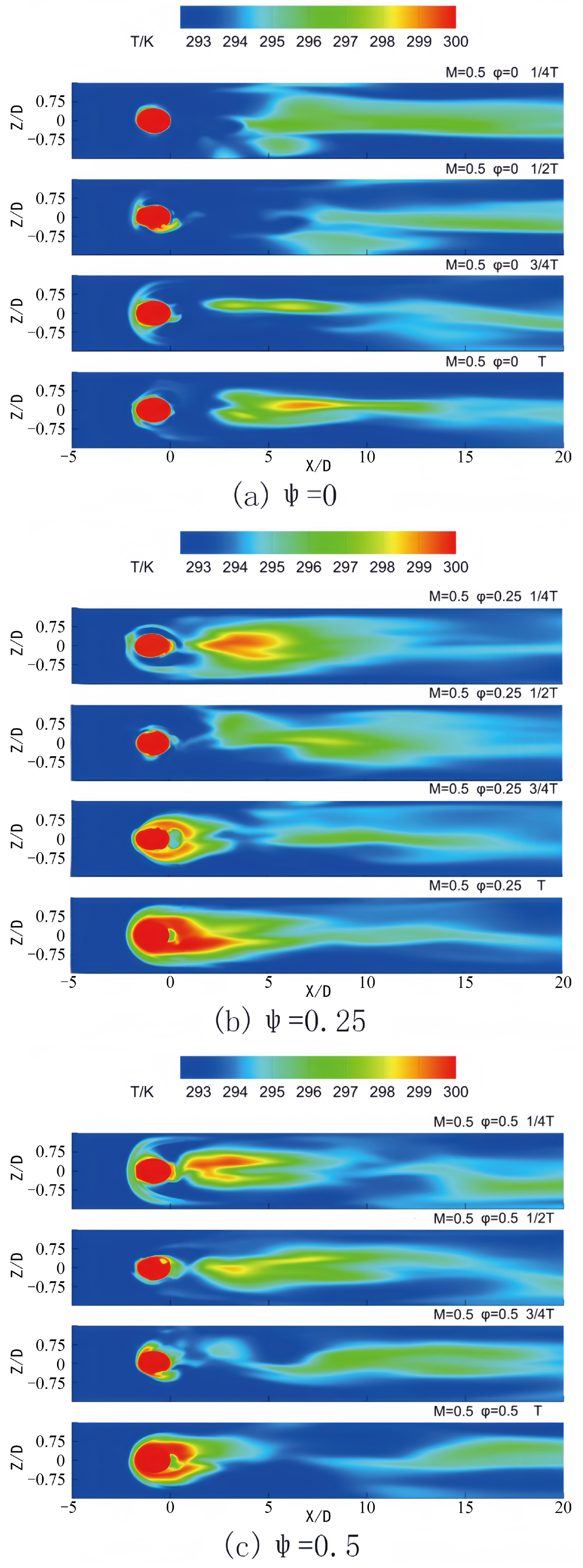
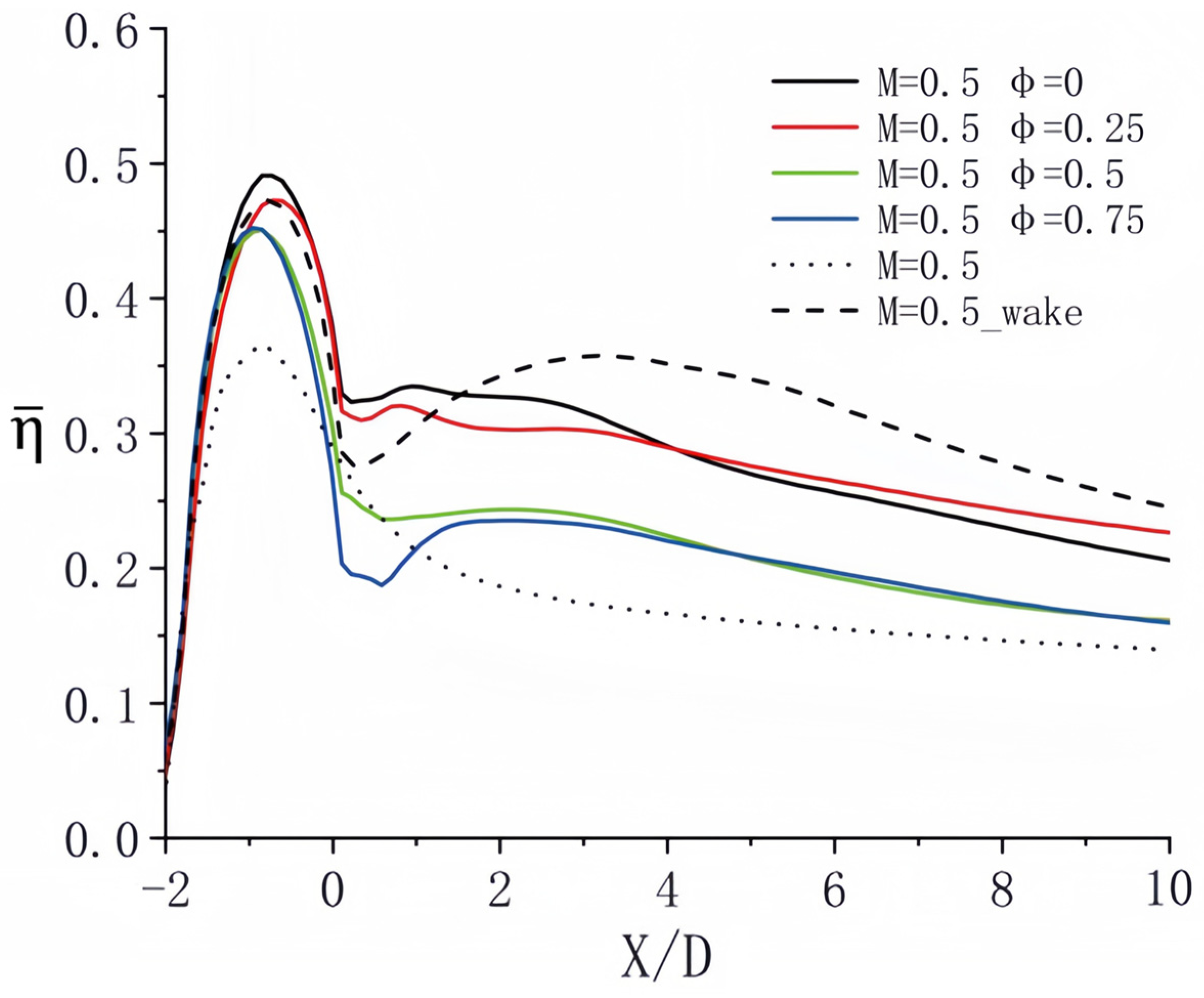
  • At a blowing ratio of M = 0.5, an increase in the average blowing ratio led to the predominance of the lift generated by the wake at the film hole. The jet lift induced by the wake was aligned with the high blowing ratio phase of the cycle. Consequently, when this lift coincided, the influence of the wake on jet pulsation was relatively diminished.
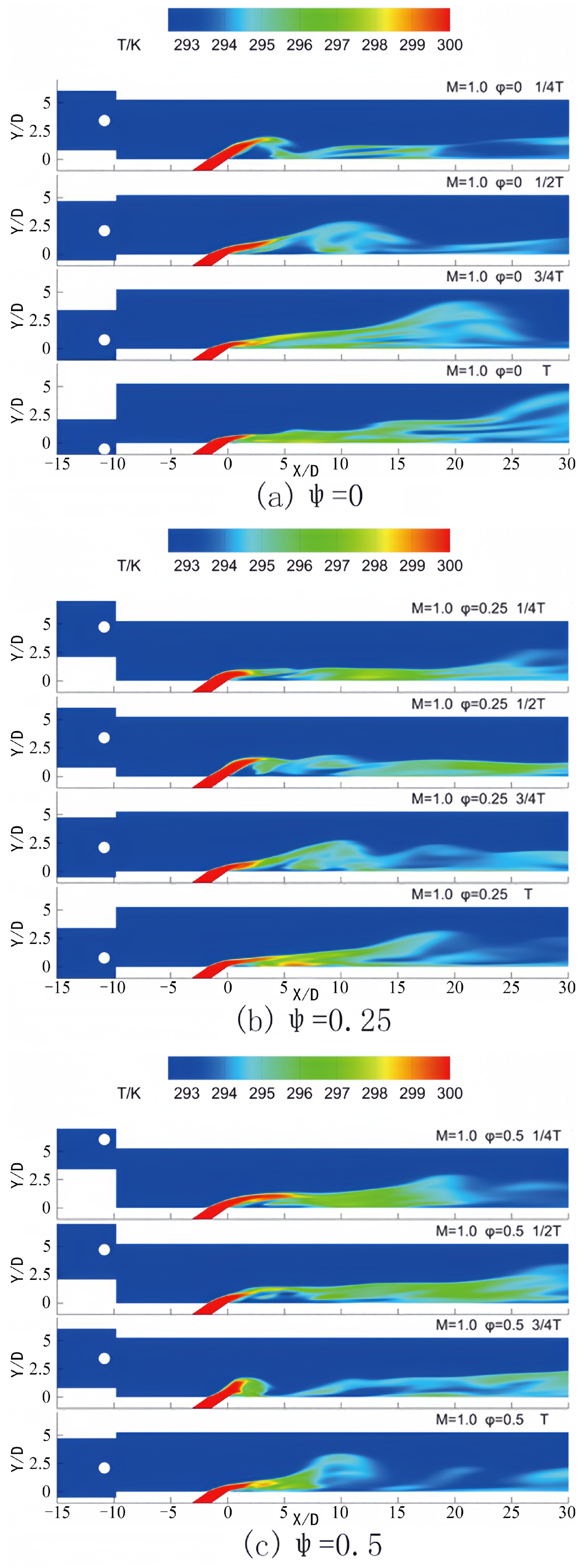
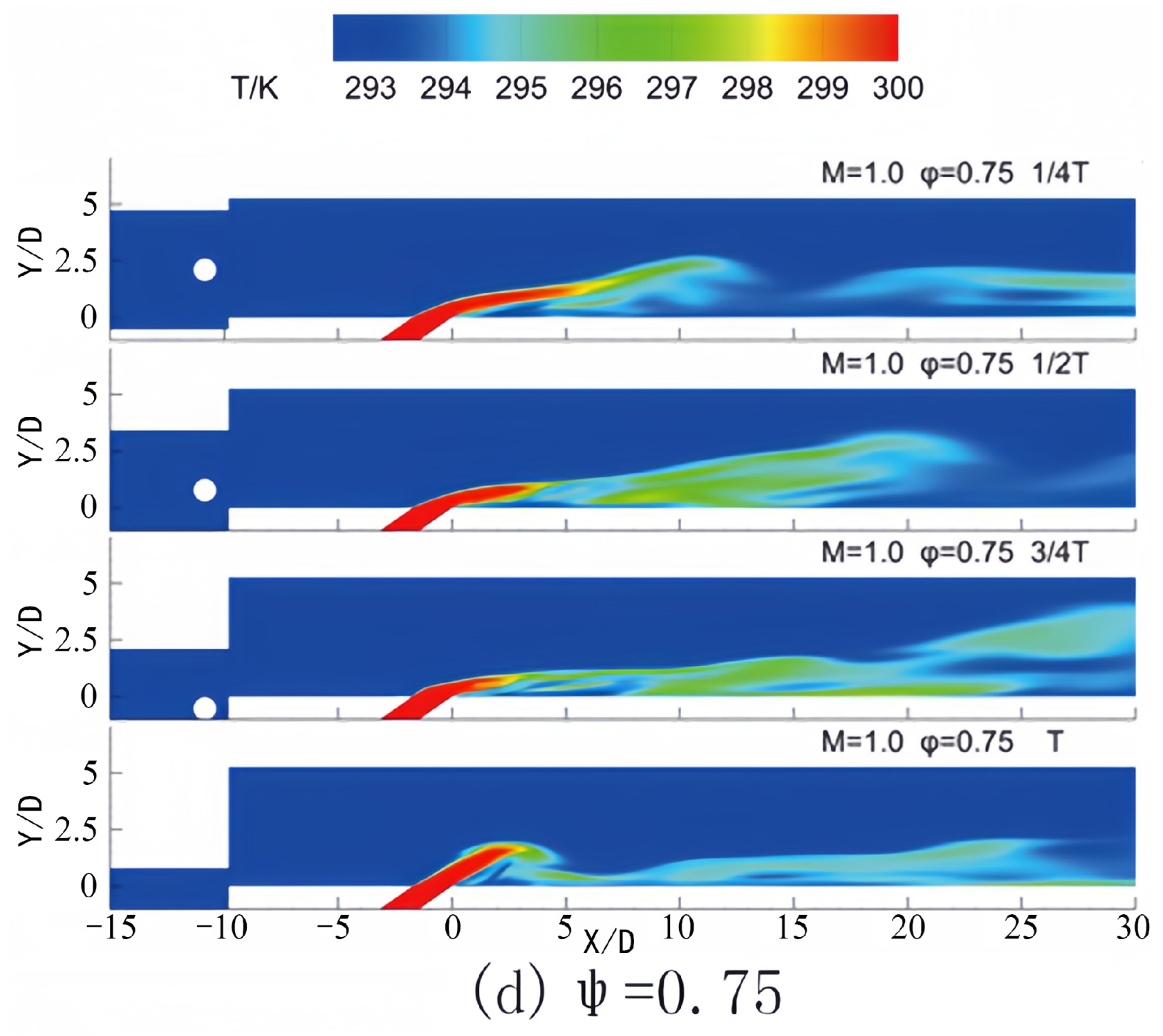
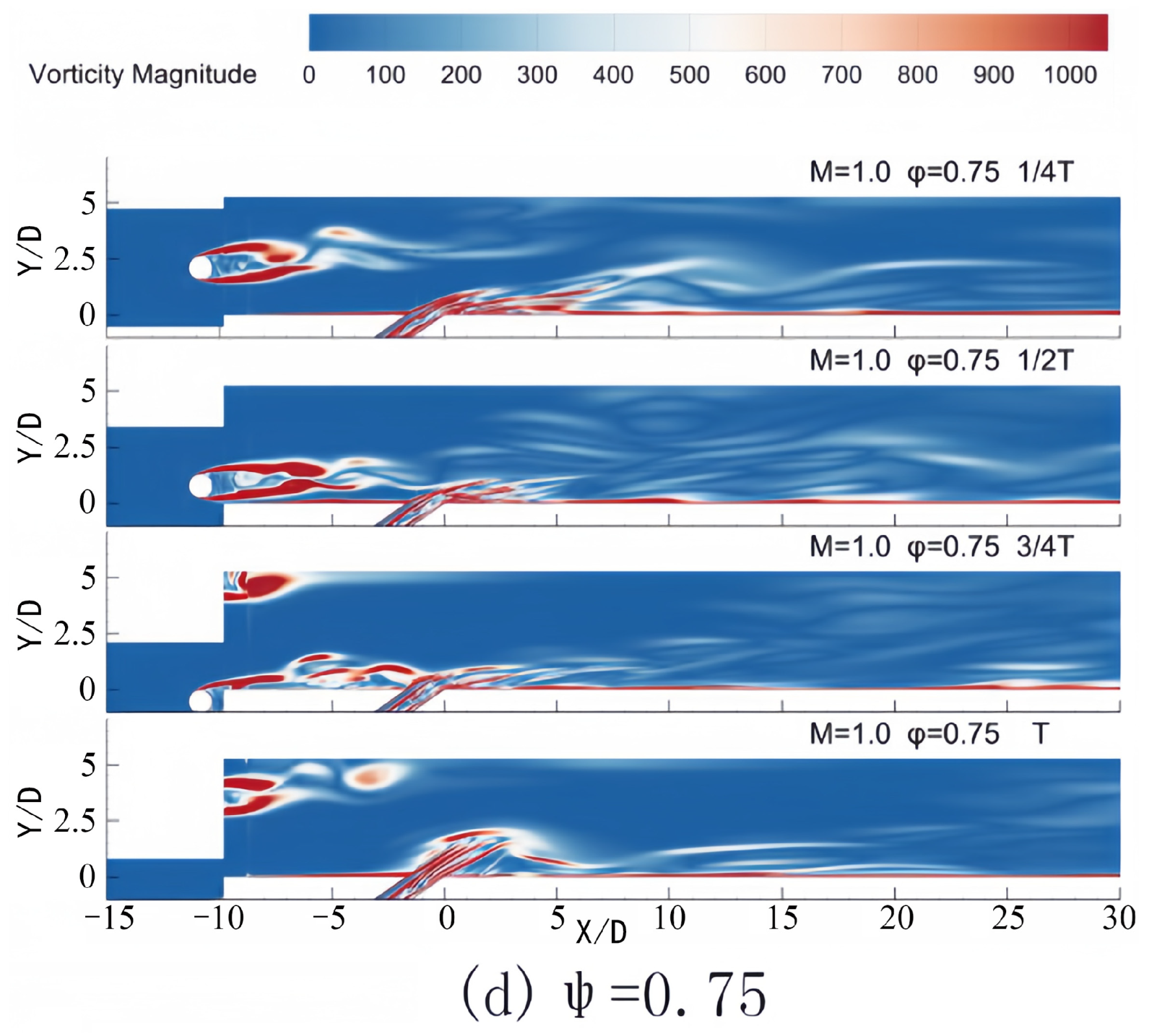
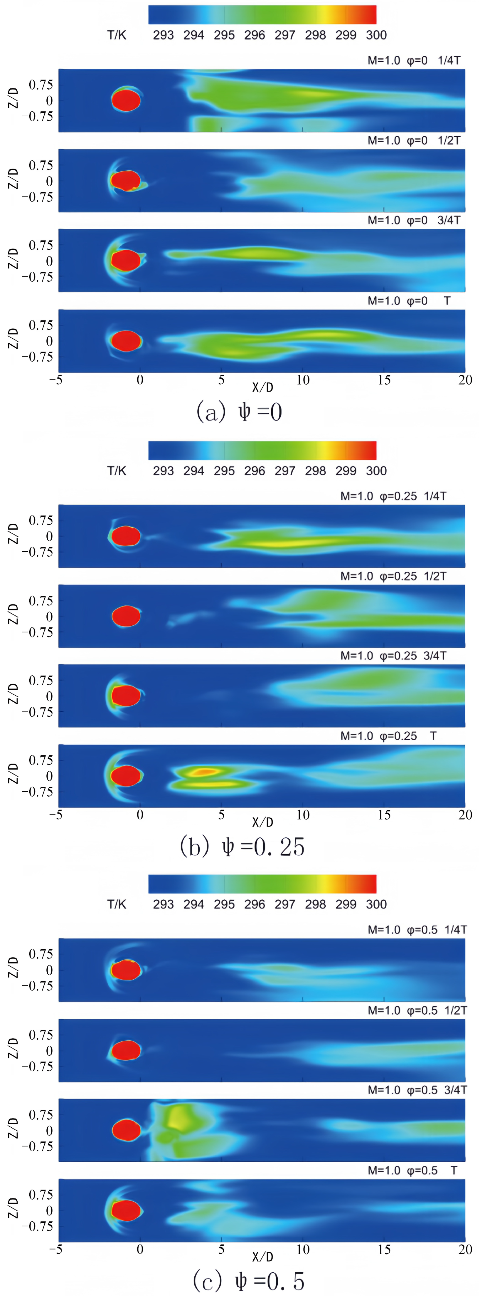
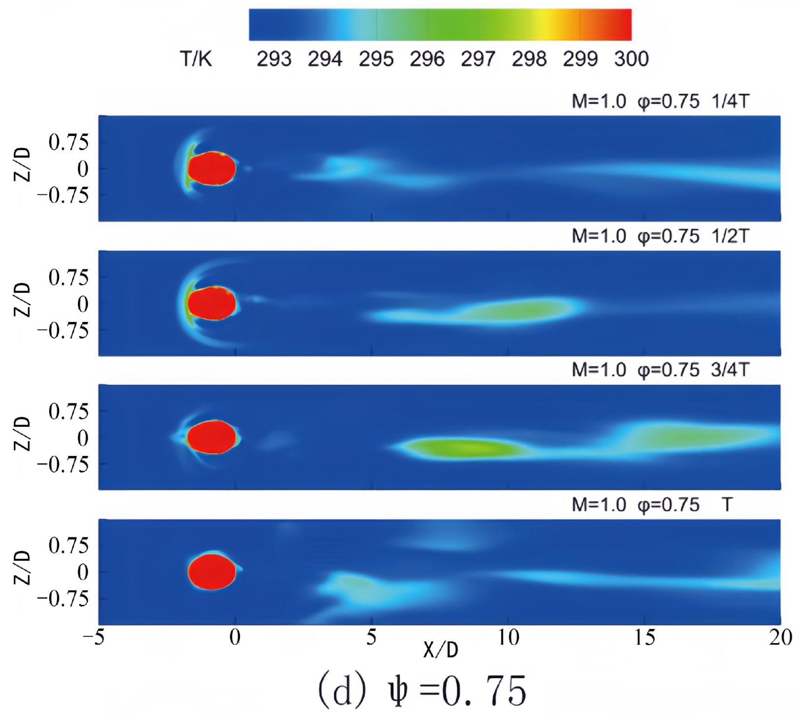
  • At a blowing ratio of M = 1.0, the elevated average blowing ratio caused significant jet lift. The wake’s influence on the film’s cooling efficiency was primarily concentrated on the leading and trailing edges of the lifted area. The interaction at these regions encouraged the higher jet to adhere closely to the wall, thereby enhancing the film-cooling effect.
  • In scenarios where the blowing ratio was low, coupling the wake-affected surface with the low-blowing ratio stage of the pulsating jet can achieve improved film cooling efficiency. Conversely, at higher blowing ratios, integrating the pulsating low-pressure phase at the film hole with the jet pulsating high-blowing ratio can optimize the film cooling effect. When the phase difference was equal to zero, the cooling efficiency of the pulsating film attains its peak across all blowing ratios, indicating a highly effective coupling strategy.

Author Contributions

Conceptualization, L.S.; methodology, L.S. and Q.P.; software, Q.P.; validation, Q.P.; formal analysis, Q.P. and L.S.; investigation, Q.P. and L.S.; resources, L.S.; data curation, Q.P.; writing—original draft preparation, Q.P.; writing—review and editing, Q.P. and L.S.; visualization, Q.P.; supervision, L.S.; project administration, L.S.; funding acquisition, L.S. All authors have read and agreed to the published version of the manuscript.

Funding

This research is supported by the National Natural Science Foundation of China (Grant No. 12172227).

Institutional Review Board Statement

Not applicable.

Informed Consent Statement

Not applicable.

Data Availability Statement

Some or all data and models used during this study are available from the corresponding author upon request.

Conflicts of Interest

The authors declare no conflicts of interest.

Nomenclature

Ddiameter of the hole, mm
Mblowing ratio
Tcycle of the jet, s
T a w adiabatic wall surface temperature, K
T j e t jet temperature, K
T main flow temperature, K
u c coolant velocity, m/s
u mainstream velocity, m/s
xStreamwise coordinate
yvertical coordinate
zspanwise coordinate
Greek symbols
ρ c coolant density, kg/m3
ρ mainstream density, kg/m3
η adiabatic film cooling efficiency
η ¯ averaged film cooling efficiency
ψ phase lag, T

References

  1. Zhang, J.; Zhang, S.; Wang, C.; Tan, X. Recent advances in film cooling enhancement: A review. Chin. J. Aeronaut. 2020, 33, 1119–1136. [Google Scholar] [CrossRef]
  2. Jia, Q.; Du, W.; Li, X.; Luo, L.; Jiao, Y.; Yan, H. Effects of blowing ratios and lip thicknesses on film cooling for trailing edge cutback with latticework ducts. Appl. Therm. Eng. 2024, 252, 123640. [Google Scholar] [CrossRef]
  3. Cao, N.; Li, X.; Wu, Z.; Luo, X. Effect of film hole geometry and blowing ratio on film cooling performance. Appl. Therm. Eng. 2020, 165, 114578. [Google Scholar] [CrossRef]
  4. Wang, C.; Wang, Y.; Wang, H.; Zhang, J.; Alting, S.A. Effect of coolant pulsation on film cooling performance on flat plate. Appl. Therm. Eng. 2023, 219, 119493. [Google Scholar] [CrossRef]
  5. Wang, Y.; Luo, Z.; Zhou, Y.; Peng, W. Large eddy simulation of pulsating film cooling on turbine vane. Aerosp. Sci. Technol. 2024, 148, 109103. [Google Scholar] [CrossRef]
  6. Song, H.; Ye, L.; Wang, X.; Liu, C.; Liang, X.; Ji, X. Assessing the effect of swirl flow on the film cooling effectiveness of a vane pressure surface. Int. Commun. Heat Mass Transf. 2025, 160, 108327. [Google Scholar] [CrossRef]
  7. Goldstein, R.J. Film Cooling. Adv. Heat Transf. 1971, 7, 321–379. [Google Scholar]
  8. Cheng, H.; Wen, Z.X.; Zhao, Y.C.; Wu, Z.Y.; Ren, X.; Yue, Z.F. Effect and optimization of geometric parameters and arrangement on film cooling performance of fan-shaped holes based on generalized regression neural network. Int. Commun. Heat Mass Transf. 2024, 158, 107868. [Google Scholar] [CrossRef]
  9. Ni, H.; Wang, M.J.; Jiang, P.X.; Peng, W.; Zhu, Y.H. A numerical study of segmented cooling-stream injection in supersonic film cooling. Chin. J. Aeronaut. 2022, 35, 156–171. [Google Scholar] [CrossRef]
  10. Saeed, R.; Khodayar, J.; Ali, A.; Vahid, V. Proposal of innovative arc-shaped wall-jet film cooling: A numerical investigation. Int. J. Thermofluids 2024, 24, 100842. [Google Scholar]
  11. Li, B.R.; Liu, C.L.; Ye, L.; Ren, M.; Wang, S.Y.; Liu, S. Film cooling performance evaluation of bi-directional diffusion hole with compound-angle on turbine blade: Study on spanwise width. Appl. Therm. Eng. 2024, 256, 124122. [Google Scholar] [CrossRef]
  12. Huang, Y.; Zhang, J.Z.; Wang, C.H.; Zhu, X.D. Multi-objective optimization of laidback fan-shaped film cooling hole on turbine vane suction surface. Heat Mass Transf. 2019, 55, 1181–1194. [Google Scholar] [CrossRef]
  13. Kalghatgi, P.; Acharya, S. Improved film cooling effectiveness with a round film cooling hole embedded in a contoured crater. J. Turbomach. 2015, 137, 101006. [Google Scholar] [CrossRef]
  14. Zhang, S.C.; Zhang, J.Z.; Tan, X.M. Improvement on shaped-hole film cooling effectiveness by integrating upstream sand-dune-shaped ramps. Chin. J. Aeronaut. 2021, 34, 42–55. [Google Scholar] [CrossRef]
  15. Kim, J.H.; Kang, C.W. A novel design for film-cooling: Cooling holes with inlet groove. Int. J. Therm. Sci. 2024, 195, 108649. [Google Scholar] [CrossRef]
  16. Zhang, K.; Li, Z.; Hao, M.; Li, Z.; Li, J. Experimental and numerical study on integrated film cooling of turbine endwall by upstream slot leakage and blade showerhead jets. Appl. Therm. Eng. 2024, 257, 124423. [Google Scholar] [CrossRef]
  17. Yang, X.; Zhao, Q.; Feng, Z. Experimental evaluation of cooling effectiveness from novel film holes over turbine endwalls with inlet swirl. Int. J. Therm. Sci. 2022, 174, 107434. [Google Scholar] [CrossRef]
  18. Yang, X.; Zhao, Q.; Wu, H.; Feng, Z. Film cooling effectiveness from upstream purge slots of a turbine vane endwall: Experiment, modeling, and correlation. Int. J. Heat Mass Transf. 2024, 219, 124899. [Google Scholar] [CrossRef]
  19. Yang, X.; Zhang, K.; Wu, J.; Lei, J.; Su, P.; Fang, Y. Numerical analysis of vane endwall film cooling and heat transfer with different mainstream turbulence intensities and blowing ratios. Int. J. Therm. Sci. 2022, 175, 107482. [Google Scholar] [CrossRef]
  20. Xu, Q.; Du, Q.; Wang, P.; Xiao, X. Numerical investigation of blowing ratio, density ratio and axial position of film holes on the vane endwall film cooling effectiveness with upstream step. Proc. Inst. Mech. Eng. Part G J. Aerosp. Eng. 2022, 236, 541–553. [Google Scholar] [CrossRef]
  21. Vargas, S.G.; Alvarado, G.D.; Daza, D.C. The Effects of Mainstream Reynolds Number and Blowing Ratio on Film Cooling of Gas Turbine Vanes. Fluids 2023, 8, 263. [Google Scholar] [CrossRef]
  22. Liu, Y.; Jia, Y.; He, X.; Meng, Z.; Xia, G.; Li, K. Investigation of the endwall film holes layout strategy based on the conjugate temperature gradient distribution in gas turbine blade cooling. Appl. Therm. Eng. 2025, 263, 125447. [Google Scholar] [CrossRef]
  23. Bogard, D.G.; Thole, K. A Gas Turbine Film Cooling. J. Propuls. Power 2012, 22, 249–270. [Google Scholar] [CrossRef]
  24. Zhao, Z.; Wen, F.; Tang, X.; Song, J.; Wang, Z. Large eddy simulation of pulsed film cooling with vortex generators. Int. J. Heat Mass Transf. 2021, 180, 121806. [Google Scholar] [CrossRef]
  25. Ke, Z.; Wang, J. Numerical investigations of pulsed film cooling on an entire turbine vane. Appl. Therm. Eng. 2015, 87, 117–126. [Google Scholar] [CrossRef]
  26. Du, K.; Pei, X.; Liang, T.; Wang, H.; Liu, C.; Sunden, B. Experimental and computational investigation of the regional endwall cooling performance considering influences of film holes layouts and purge slot shape. Therm. Sci. Eng. Prog. 2025, 59, 103333. [Google Scholar] [CrossRef]
  27. Hossain, A.M.; Ameri, A.; Gregory, W.J.; Bons, J.P. Sweeping Jet Film Cooling at High Blowing Ratio on a Turbine Vane. J. Turbomach. 2020, 142, 121010. [Google Scholar] [CrossRef]
  28. Ye, Q.; Zhang, Y.; Wei, J. A comprehensive review of pulsating flow on heat transfer enhancement. Appl. Therm. Eng. 2021, 196, 117275. [Google Scholar] [CrossRef]
  29. Du, W.; Luo, L.; Wang, S.; Sunden, B. Film cooling in the trailing edge cutback with different land shapes and blowing ratios. Int. Commun. Heat Mass Transf. 2021, 125, 105311. [Google Scholar] [CrossRef]
  30. Wang, Q.; Moosania, M.; Zhou, C. Effects of an incoming vortex on the film cooling jet. Int. J. Heat Mass Transf. 2021, 185, 122323. [Google Scholar] [CrossRef]
  31. Sultan, Q.; Lalizel, G.; Fenot, M.; Dorignac, E. Influence of coolant jet pulsation on the convective film cooling of an adiabatic wall. J. Heat Transf. 2017, 139, 022201. [Google Scholar] [CrossRef]
  32. Burdet, A.; Abhari, R.S. Influence of Near Hole Pressure Fluctuation on the Thermal Protection of a Film-Cooled Flat Plate. J. Heat Transfer. 2009, 131, 022202. [Google Scholar] [CrossRef]
  33. Huo, D.C.; Fang, H.L.; Gao, J.; Liao, Y.N.; Jiang, Z.Y. Unsteady vane-rotor secondary flow interaction of the endwall region in a 1.5-stage variable-geometry turbine. Energy 2024, 309, 133027. [Google Scholar] [CrossRef]
  34. Wang, T.Y.; Xuan, Y.M.; Han, X.S. The effects of stator-rotor interaction on unsteady characteristics of turbine tip leakage flow. Aerosp. Sci. Technol. 2023, 141, 108544. [Google Scholar] [CrossRef]
  35. Chen, D.W.; Zhu, H.R.; Liu, C.L.; Li, H.T.; Li, B.R.; Zhou, D.E. Combined effects of unsteady wake and free-stream turbulence on turbine blade film cooling with laid-back fan-shaped holes using PSP technique. Int. J. Heat Mass Transf. 2019, 133, 382–392. [Google Scholar] [CrossRef]
  36. Abadi, S.M.H.B.; Zirak, S.; Zargarabadi, M.R. Effect of pulsating injection and mainstream attack angle on film cooling performance of a gas turbine blade. Phys. Fluids 2020, 32, 117102. [Google Scholar] [CrossRef]
  37. Zhao, Z.; Wen, F.; Li, Z.; Wan, C.; Zhang, X.; Wang, S. Effects of vortex generators and pulsation on compound angle film cooling. Appl. Therm. Eng. 2024, 244, 122737. [Google Scholar] [CrossRef]
  38. Li, F.; Liu, Z.; Tao, Y.; Zhang, W.; Feng, Z. A conjugate study on the application of combined impingement and film cooling for a turbine blade tip. Appl. Therm. Eng. 2024, 252, 123594. [Google Scholar] [CrossRef]
  39. Wang, L.; Li, H.; Xie, G.; Zhou, Z. Effect of blowing ratio, rotation, and film hole row location on film cooling on the suction surface of a rotating turbine blade. Int. J. Heat Mass Transf. 2023, 208, 124048. [Google Scholar] [CrossRef]
  40. Coulthard, S.M.; Volino, R.J.; Flack, K.A. Effect of Jet Pulsing on Film Cooling: Part 1—Effectiveness and Flowfield Temperature Results. J. Turbomach. 2007, 129, 232–246. [Google Scholar] [CrossRef]
Figure 1. Schematic diagram of the computational domain and grid. (a) computational domain; (b) grid.
Applsci 15 02558 g001
Figure 2. Variation of phase lag between the rod and the pulsating jet.
Applsci 15 02558 g002
Figure 3. Comparison of cooling efficiency of various grid sets along the centerline with experimental results [40].
Applsci 15 02558 g003
Figure 4. Comparison of cooling efficiency along the centerline for different turbulence models with experimental results [40].
Applsci 15 02558 g004
Figure 5. Contours of temperature in one period for different phase lags in Z = 0 at M = 0.3.
Applsci 15 02558 g005aApplsci 15 02558 g005b
Figure 6. Contours of vorticity in one period for different phase lags in Z = 0 at M = 0.3.
Applsci 15 02558 g006aApplsci 15 02558 g006b
Figure 7. Contours of temperature on the bottom wall in one period for different phase lags at M = 0.3.
Applsci 15 02558 g007aApplsci 15 02558 g007b
Figure 8. Streamwise distribution of time-mean span averaged film cooling efficiency at M = 0.3.
Applsci 15 02558 g008
Figure 9. Contours of temperature in one period for different phase lags in Z = 0 at M = 0.5.
Applsci 15 02558 g009aApplsci 15 02558 g009b
Figure 10. Contours of vorticity in one period for different phase lags in Z = 0 at M = 0.5.
Applsci 15 02558 g010aApplsci 15 02558 g010b
Figure 11. Contours of temperature on the bottom wall in one period for different phase lags at M = 0.5.
Applsci 15 02558 g011aApplsci 15 02558 g011b
Figure 12. Streamwise distribution of time-mean span averaged film cooling efficiency at M = 0.5.
Applsci 15 02558 g012
Figure 13. Contours of temperature in one period for different phase lags in Z = 0 at M = 1.0.
Applsci 15 02558 g013aApplsci 15 02558 g013b
Figure 14. Contours of vorticity in one period for different phase lags in Z = 0 at M = 1.0.
Applsci 15 02558 g014aApplsci 15 02558 g014b
Figure 15. Contours of temperature on the bottom wall in one period for different phase lags at M = 1.0.
Applsci 15 02558 g015aApplsci 15 02558 g015b
Figure 16. Streamwise distribution of time-mean span averaged film cooling efficiency at M = 1.0.
Applsci 15 02558 g016
Disclaimer/Publisher’s Note: The statements, opinions and data contained in all publications are solely those of the individual author(s) and contributor(s) and not of MDPI and/or the editor(s). MDPI and/or the editor(s) disclaim responsibility for any injury to people or property resulting from any ideas, methods, instructions or products referred to in the content.

