Article

316L Austenitic Stainless Steel Deformation Organization and Nitriding-Strengthened Layer Relationships

School of Materials Science and Engineering, Hebei University of Technology, Tianjin 300401, China
*
Author to whom correspondence should be addressed.
Appl. Sci. 2025, 15(5), 2352; https://doi.org/10.3390/app15052352
Submission received: 17 January 2025 / Revised: 12 February 2025 / Accepted: 21 February 2025 / Published: 22 February 2025
(This article belongs to the Section Surface Sciences and Technology)

Abstract

:
The organizational development of 316L austenitic stainless steel was examined in this work under various levels of compression deformation (0, 10%, 20%, 30%, 40%, and 50%) and thoroughly investigated at multiple scales using SEM and EBSD techniques. The 316L austenitic stainless steel was subjected to varying degrees of deformation and underwent glow ion nitriding treatment at 500 °C to examine into the impact of deformation on ion nitriding behavior. The results indicated that as the level of deformation increased, the martensite content gradually rose, the hardness progressively increased, and the depth of the nitrided layer continuously expanded. Specifically, the hardness of the material and the depth of the nitrided layer were relatively low at minimal deformation, while both the hardness and the thickness of the nitrided layer increased significantly when the deformation was raised to 30%. This suggests that pre-compression deformation treatment can substantially enhance the ion nitriding effectiveness of 316L austenitic stainless steel, thereby improving the material’s hardness on the surface and its resistance to wear. This study offers a crucial theoretical foundation and experimental data for the purpose of surface investigation.

1. Introduction

Austenitic stainless steel exhibits significant potential for application in various industries [1], including the aerospace and petrochemical sectors, owing to its remarkable corrosion resistance, high toughness, and favorable machinability. However, the inherent hardness, wear resistance, and fatigue resistance of this material impose considerable limitations on the service life of components fabricated from it. Ion nitriding technology offers several advantages by enabling substantial alterations in the nitriding temperature [2], which can optimize the microstructural characteristics and mechanical properties of the designated penetration layer. Glow ion nitriding, in particular, is characterized by rapid nitriding rates, minimal thermal deformation, and a robust connection between the surface layer and the substrate. Consequently, it is extensively employed to enhance the surface characteristics of stainless steel, thereby improving the surface hardness, wear resistance, and fatigue strength of stainless steel components [3]. Currently, an investigation into the ionic nitriding process of AISI 316L austenitic stainless steel (hereafter referred to as 316L stainless steel) has been conducted at low temperatures (approximately 500 °C) has been documented. However, while there are numerous studies in this area, the nitriding speed at low temperatures is significantly slower compared to that achieved through high-temperature ionic nitriding, resulting in only marginal improvements in surface hardness [4]. These limitations hinder the advancement and widespread adoption of nitriding surface treatment technologies for stainless steel [5]. To address these challenges, enhancing the diffusion rate of nitrogen atoms is essential for increasing the thickness of the nitriding layer on the surface of stainless steel, thereby improving its hardness and wear resistance. Cold deformation can introduce additional dislocations and defects within austenitic stainless steel, which serve as rapid pathways for atomic diffusion [6,7,8]. Therefore, this study investigates the combination of the room-temperature deformation of 316L stainless steel subjected to low-temperature ion nitriding technology. This study investigates the impact of different levels of compressive deformation on the microstructure and properties of 316L stainless steel subsequent to low-temperature nitriding, with the aim of accelerating the ion nitriding process and achieving performance levels of the low-temperature-nitriding-reinforced layer comparable to those obtained through high-temperature nitriding.

2. Materials and Methods

2.1. Materials

The experimental material utilized in this research was 316L austenitic stainless steel, with its XRD (X-ray diffraction, Smart lab 9KW) pattern and microstructure illustrated in Figure 1. Its chemical composition is detailed in Table 1. The XRD analysis validated that the test material was single-phase austenitic, while the metallographic analysis revealed distinct coarse equiaxed austenite grains, accompanied by the presence of a limited number of twins.

2.2. Pre-Treatment

The samples were subjected to a high-temperature treatment in a chamber resistance furnace (RTX-8-13) at 1050 °C for 30 min. Subsequently, the materials were subjected to quenching in water to enhance the efficiency of the subsequent processing stages. Standard compression specimens were prepared in accordance with the metal compression test standard GB/T7314-2017 [9]. The 316L stainless steel was cut to ϕ10 × 15 mm using wire cutting techniques and the specimens were then compressed at room temperature to achieve plastic deformations of 0, 10%, 20%, 30%, 40%, and 50% of the standard deformation. The shape variable was calculated according to the following formula:
ε = L 0 L L 0 × 100 %
The variables L0 and L represent the lengths of the specimen prior to and subsequent to deformation, respectively. The compression tests were performed utilizing a WDW-200Y universal testing machine, maintaining a moving speed of 1 mm/min.

2.3. Low-Temperature Plasma Nitriding Treatment

The nitriding apparatus utilized in this experiment was the LDMC-30F, a touchscreen computer-controlled pulse-powered glow ion nitriding furnace manufactured by the Wuhan Heat Treatment Research Institute. Ion nitriding was performed on the specimens under varying deformation conditions. The nitriding process was executed in a glow ion nitriding furnace, with the specific parameters outlined in Table 2.

2.4. Microstructure Characterization

Following the completion of nitriding, the samples were etched by Marble’s reagent (1 g of CuSO4 + 10 mL of HCl + 10 mL of C2H5OH), and then the microstructural characteristics of the deformed and nitrided the samples were analyzed.
An advanced, fully automated AxioImage type ZEISS metallurgical microscope (Axio Imager M2m) was employed to examine the metallographic morphology of the cross-section of the composite nitrided samples, as well as the metallographic structure of the nitrided substrate prior to nitriding. Additionally, this microscope facilitated the measurement of the thickness of the nitrided layer.
Following the low-temperature plasma nitriding process, the surface morphologies of the samples were examined using a SEM (scanning electron microscope, JSM 7610F). The EDS (Energy dispersive spectroscopy, TSL EDAX) analyses were conducted at a test voltage of 20 kV and a current of 0.1 nA.
The physical phase analysis of the specimen was conducted using an XRD, which operated within a scanning range of 10~90°. The scanning was performed at a speed of 6 °/min, with a voltage of 40 kV and a current of 50 mA. The test used Cu Kα radiation (λ = 0.15418 nm). Subsequent data analysis was performed utilizing Jade (8.0) software.
EBSD (electron backscatter diffraction, Nordlys Nano HKL-EBSD) was employed to investigate the deformation mechanisms of the samples post-deformation. The data acquired through EBSD were analyzed utilizing the post-processing software AztecCrystal (2.1), developed by Oxford Instruments. This analysis aimed to extract information regarding the morphology of the microstructure, the distribution of grain boundaries, and the characteristics of weaving.

2.5. Property Test

Following the grinding and polishing of the samples using sandpaper with mesh sizes ranging from 200 to 1500, microhardness assessments were conducted utilizing a microhardness tester (HVM-G-XY-S). These tests were performed on the samples both prior to and subsequent to deformation, as well as before and after the nitriding treatments. A load of 0.05 N was applied for a duration of 15 s during the testing process. The specific hardness values were automatically calculated by manually adjusting the testing distance, with each measurement point being tested five times to obtain an average value.
The corrosion resistance assessment was conducted utilizing the CHI600E electrochemical workstation manufactured by Shanghai Chenhua. The evaluation of the nitrided layer’s corrosion resistance was performed through a dynamic potential anodic polarization curve, employing a three-electrode configuration. This configuration comprised a platinum electrode as the auxiliary electrode, a saturated mercuric glycol electrode as the reference electrode, and the test specimen serving as the working electrode. During the testing procedure, a 3.5 wt% NaCl solution was utilized as the electrolyte, while the nitrided specimen was coated with silica gel resin. The working surface was exposed to the electrolyte through a small circular aperture with a diameter of 10 mm. Prior to the test, an open-circuit voltage measurement was conducted for 400 s at room temperature. Subsequently, Tafel polarization curves were generated until the open-circuit potential stabilized, at which point data collection commenced. The self-corrosion current was determined through analysis using the instrument’s software. The self-corrosion current density was calculated, and the corrosion resistance of the test sample was evaluated in conjunction with its self-corrosion potential.

3. Results

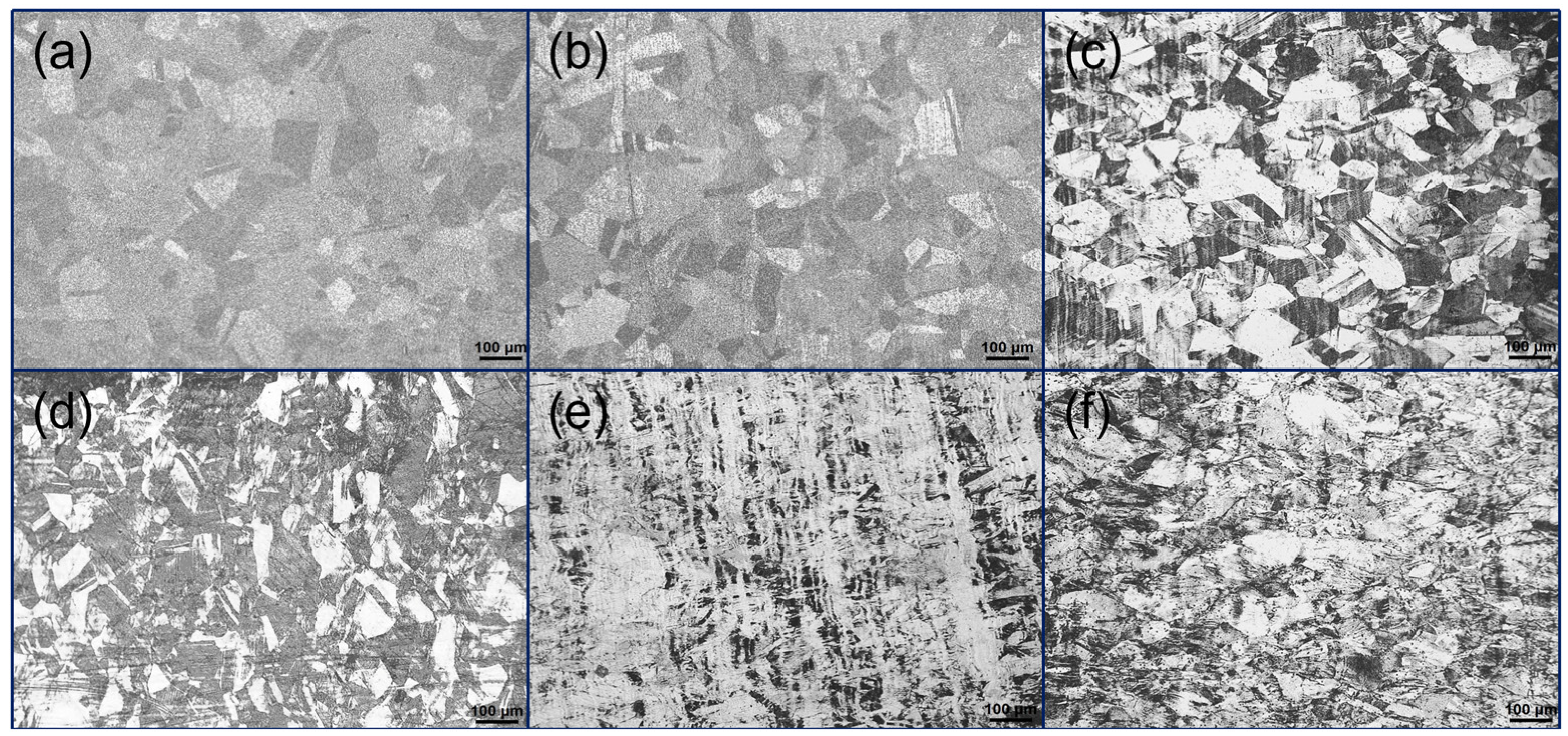
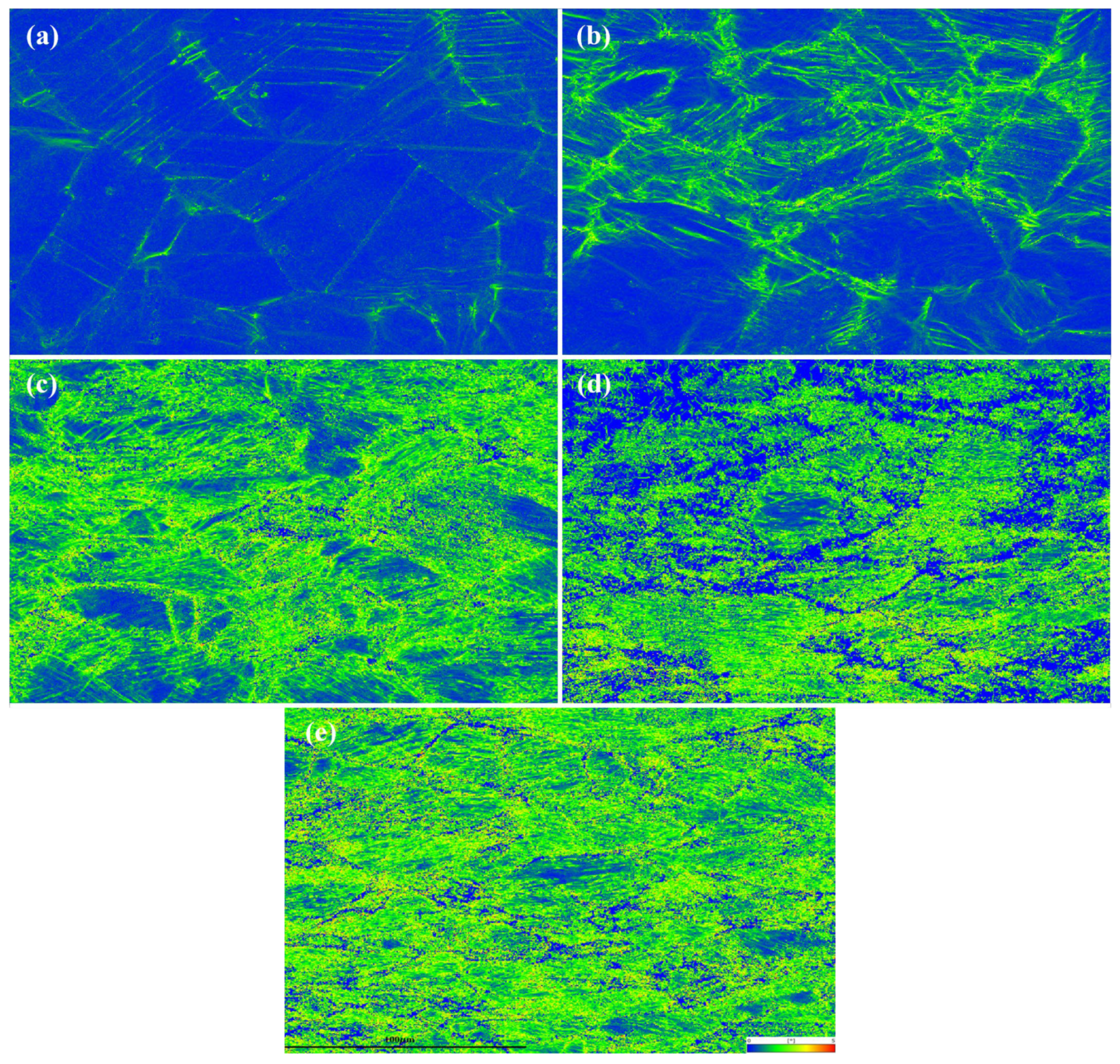
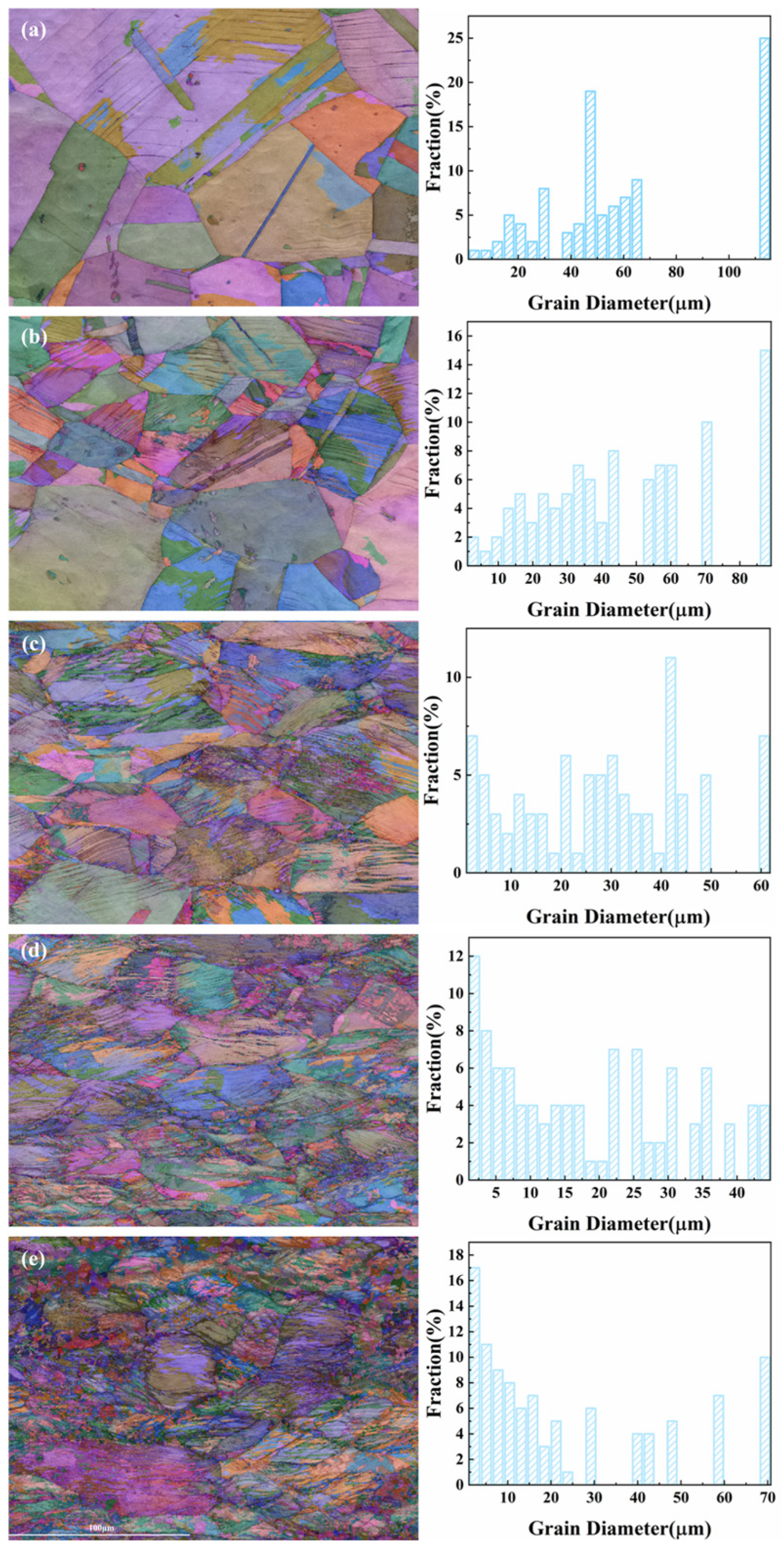
3.1. Microstructure of 316L Austenitic Stainless Steel After Different Deformation Treatment
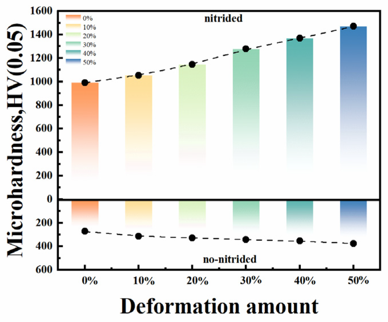
The metallographic structure of 316L stainless steel after deformation under various conditions is illustrated in Figure 2. After 10% deformation, the degree of grain distortion is relatively minor; however, the grain size is significantly reduced compared to the original size, and the number of grain boundaries has escalated considerably. In comparison to the 10% deformed sample, it is observed that after 30% deformation, the martensite fraction does not exhibit substantial differences. Nevertheless, the degree of grain distortion increases significantly, and numerous grains exhibit varying directions of deformation [8]. This includes deformation-induced martensite and slip bands, which collectively form a complex structure that is difficult to distinguish. When the deformation reaches 50%, the distortion of the grain boundaries becomes severe, resulting in unclear boundaries and an increase in the deformed structure. Compared to the original 316L stainless steel, the physical composition of the deformed specimen is primarily composed of austenite (γ) and martensite (α’) [10].

3.2. Microhardness

In general, surface hardness is directly proportional to wear resistance. The key principle in improving wear resistance through nitriding treatment is the increase in surface hardness [11]. The hardness of the substrate and the nitrided samples, both before and after deformation, was measured, and the findings are depicted in Figure 3. The average surface hardness values of the 316L stainless steel substrates at various deformation levels were measured multiple times, yielding values of 272 HV, 313 HV, 327 HV, 342 HV, 354 HV, and 376 HV, respectively. In a similar manner, the average surface values of the nitrided samples at different deformation levels were 992 HV, 1054 HV, 1146 HV, 1278 HV, 1369 HV, and 1470 HV, respectively. The nitrided specimens were significantly harder than the non-nitrided specimens [12]. As presented in Figure 3, the hardness of the substrate of 316L stainless steel significantly increased after deformation. This is attributable to the persistent increase in dislocation density within the sample during the deformation process. The increase in dislocations results in the creation of dislocation pile-ups, which hinder the movement of dislocations and enhance the material’s resistance to deformation [13]. This effect retains the work-hardened microstructure, resulting in the elevation of the sample’s surface hardness. On the other hand, the surface hardness of the nitrided samples at different deformation levels also increased significantly with the increase in deformation. Among them, the nitrided sample with a 50% deformation level had the highest surface hardness, reaching 1470 HV, which is about five times the hardness of the substrate. This is because the density of dislocations and other defects in the 316L stainless steel significantly increased after deformation. Figure 2 illustrates that as deformation increases, the size of the grains significantly decreases, while the number of grain boundaries increases markedly. Additionally, the clarity of the grain boundaries diminishes with an increase in the volume of deformation, resulting in a progressively blurred appearance. This observation suggests that 316L austenitic stainless steel undergoes a process of homogenization and refinement of grains following low-temperature compression deformation, accompanied by a substantial increase in both the number of grain boundaries and sub-grain boundaries. During low-temperature compression deformation, slip mechanisms contribute to an elevated density of dislocations within the original grains, facilitating the formation of sub-grain boundaries. The further development of these sub-grain boundaries leads to the emergence of new grain boundaries, thereby promoting grain refinement. Furthermore, the presence of dislocations, laminations, grain boundaries, and other microstructural features significantly influences the hardness of the stainless steel. During nitriding, nitrogen atoms can fully utilize these defects for diffusion, thus increasing the diffusion rate and accelerating the growth of the nitriding layer, leading to a corresponding increase in hardness.

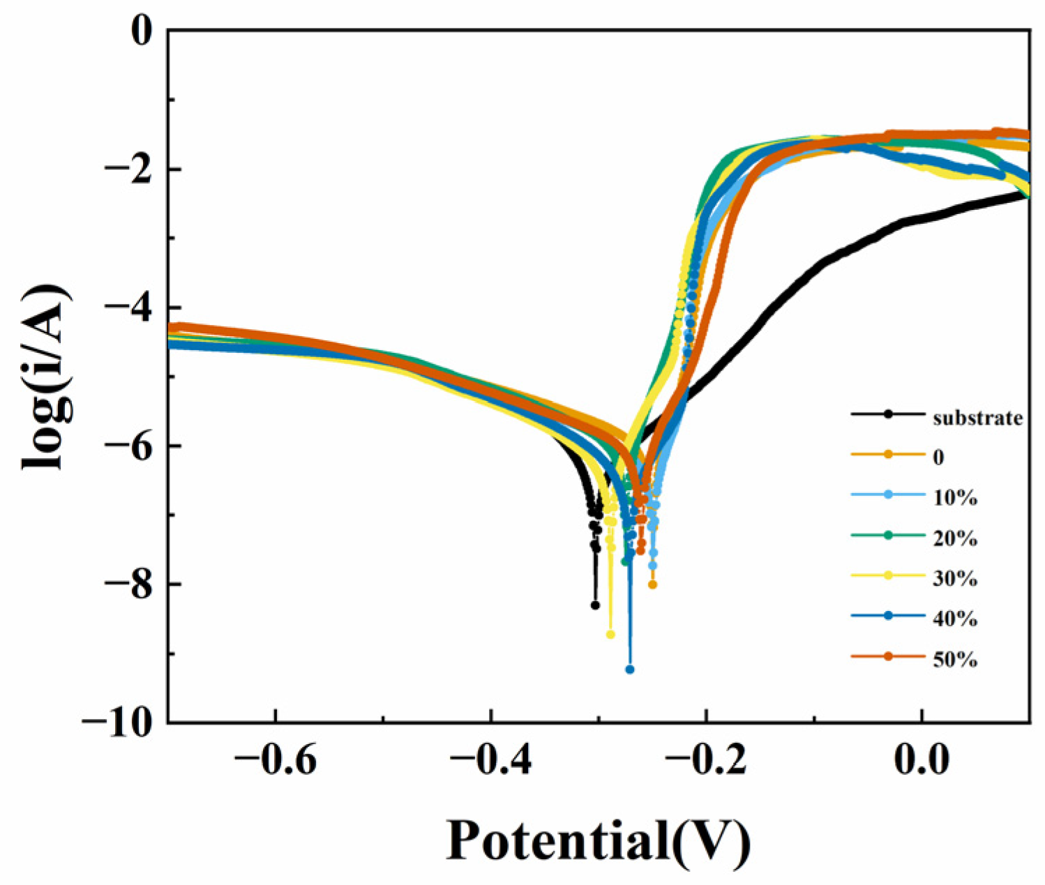
3.3. Corrosion Resistance

Figure 4 illustrates the Tafel polarization curves of the nitrided 316L stainless steel samples subjected to varying levels of deformation. The self-corrosion potential and the calculated self-corrosion current density are summarized in Table 3. The tests for corrosion resistance were carried out in a 3.5% NaCl solution. Table 3 illustrates that the matrix and the deformation of the nitrided specimens exhibit a significant disparity in self-corrosion current density results, differing by nearly an order of magnitude. This variation can be attributed to the corrosion resistance of stainless steel, which is primarily influenced by the matrix’s chromium content that facilitates the formation of a dense chromium oxide protective layer on the surface. During nitriding treatment at 500 °C, nitrogen atoms dissolve within the austenite grains, leading to their precipitation from the supersaturated austenite phase. This process results in the formation of chromium nitride through the interaction of chromium present in the matrix. The precipitation of nitrides in the nitriding layer causes the diffusion of chromium from the matrix to the surface layer, consequently diminishing the corrosion resistance. Therefore, the corrosion resistance of the nitrided specimen is reduced in comparison to that of the non-nitrided substrate. As depicted in Figure 4 and Table 3, the self-corrosion potentials of the nitrided samples with different deformation levels are comparable to those of the original samples; however, the self-corrosion current densities are generally elevated. This increase is due to the fact that, following deformation, the precipitation temperature of the chromium-rich second phases ranges from 400 to 850 °C, with their primary precipitate being the chromium carbide M23C6 [14]. During the nitriding process at 500 °C, similar compounds may form, resulting in potential differences with the CrN compounds generated during nitriding and at defect sites. Moreover, the depletion of chromium in localized areas leads to the “chromium-poor phenomenon” [15], which significantly elevates the current density during the electrochemical corrosion process and markedly diminishes pitting corrosion resistance [16]. The nitriding process, when conducted at temperatures exceeding 450 °C [17], leads to the dissolution of nitrogen atoms within the austenite grains. This nitrogen can readily precipitate from the supersaturated austenite phase and subsequently react with chromium present in the matrix to form chromium nitride. This precipitation preferentially occurs along grain boundaries, resulting in a reduction in chromium content in the surface layer of the matrix. Consequently, this phenomenon, referred to as the “chromium-poor phenomenon”, adversely affects the material’s corrosion resistance. Furthermore, after undergoing compression deformation at room temperature, 316L stainless steel exhibits a substantial number of shear bands, stacking faults, and other defects. These imperfections compromise the uniformity and chemical stability of the chromium-rich oxide film on the stainless steel’s surface. The presence of martensite can also induce the localized activation and dissolution of the oxide film, further impairing its corrosion resistance. In conclusion, an increase in deformation levels correlates with a decline in the corrosion resistance of the nitrided samples.

4. Discussion

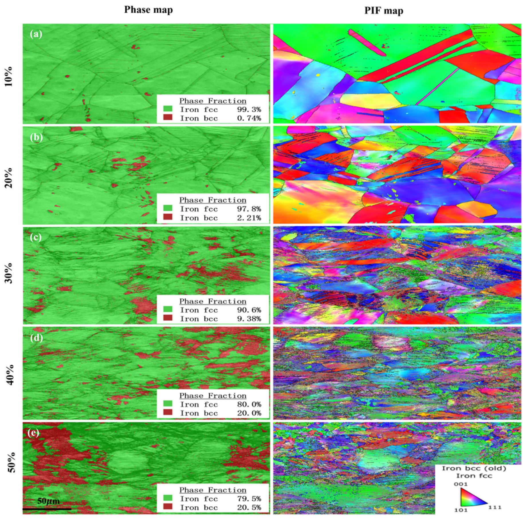
4.1. Phase Transformation Behavior During Deformation

Figure 5 illustrates the X-ray diffraction patterns of 316L stainless steel subjected to various deformation parameters. The 316L stainless steel samples exhibited the induction of martensite through deformation, specifically α’-martensite [18], following different degrees of compressive deformation. The intensity of the austenite γ (111) diffraction peaks diminish as the deformation parameters increase, indicating that α’-martensite is derived from austenite [10], and the relative content of martensite increases with the extent of deformation. XRD analysis revealed that a significant number of dislocations and other defects emerged in the 316L austenitic stainless steel during compressive deformation, bringing about the transformation of some austenite into martensite.
The following figure presents the EBSD analysis of the specimen under various deformation conditions.
The plastic deformation of 316L austenitic stainless steel, along with the slip surfaces and grain boundaries, contributes to the generation of a significant number of dislocations, leading to a distortion of the dot matrix. During the process of plastic deformation, brittle carbides and other constituents present within the grains are fractured and subsequently distributed along the direction of flow. The distribution of dislocations is also illustrated in the Kernel Average Misorientation (KAM) diagram, which indicates that the dislocation density increases with a rise in the volume of deformation. In comparison to other samples, the dislocation distribution depicted in Figure 6e exhibits a greater degree of homogeneity and a higher relative density of dislocations.
The left side of Figure 7 displays the image quality map (IQ map) of the specimen. It is evident that when the deformation variable is small, the resulting martensite structure is predominantly blocky, with a minimal presence of slaty martensite. As the deformation variable increases, the intrinsic strain and twinning structure of the martensite cause it to appear darker in the IQ map. Regarding the martensite transformation during the compression deformation of 316L stainless steel, it can be analyzed by using the phase distribution diagram of the specimen on the left side of Figure 8, where the red area represents the martensite organization and the green represents the austenite organization. From the quality of the map, it can be seen that the darker lath-like region and the map-phase distribution map of the martensite-phase (red area) overlap, but as can also be seen, there are a multitude of obvious shear zones and lath-like twin crystals and martensite nucleation in the vicinity of this; these are the favorable locations for martensite nucleation. Martensite nucleation can also occur in the range of the isolated shear zones, grain boundary/shear zones intersections, etc. [19]. From the right side of Figure 8, the orientation of the distribution maps can be seen, corresponding to the increase in deformation amount; due to the serious compression deformation, the original grain boundaries gradually become fuzzy, and only the existence of deformation twins and a large number of shear bands can be seen vaguely. The martensite contents in the specimens under different deformation amounts were calculated to be 0.74%, 2.21%, 9.38%, 20.0%, and 20.5%, respectively, which increased significantly compared with the un-compressed specimens, and with the increase in deformation amount, the content of lath-like martensite increased. When the deformation amount is larger, it makes the austenite phase and martensite cross each other, resulting in two-phase grain boundaries, which are difficult to distinguish [20]; when the deformation amount is more than 30%, the grains distinctly go through the austenite to martensite transformation, the austenite content further decreases, and the martensite content increases significantly. According to the grain-size distribution graph on the right side of Figure 7, it can be seen that after the compression deformation of the specimen, grain distribution changes are very obvious; when the morphology of the variable is more than 30%, mainly small grains dominate (nano-sized grains are the most dominant), the distribution of large grains is lower, and the overall grain size is relatively uniform, and with an increase in morphology, the number of nano-sized grains is further increased, the deformation organization is gradually refined, and the organization homogeneity is further increased.

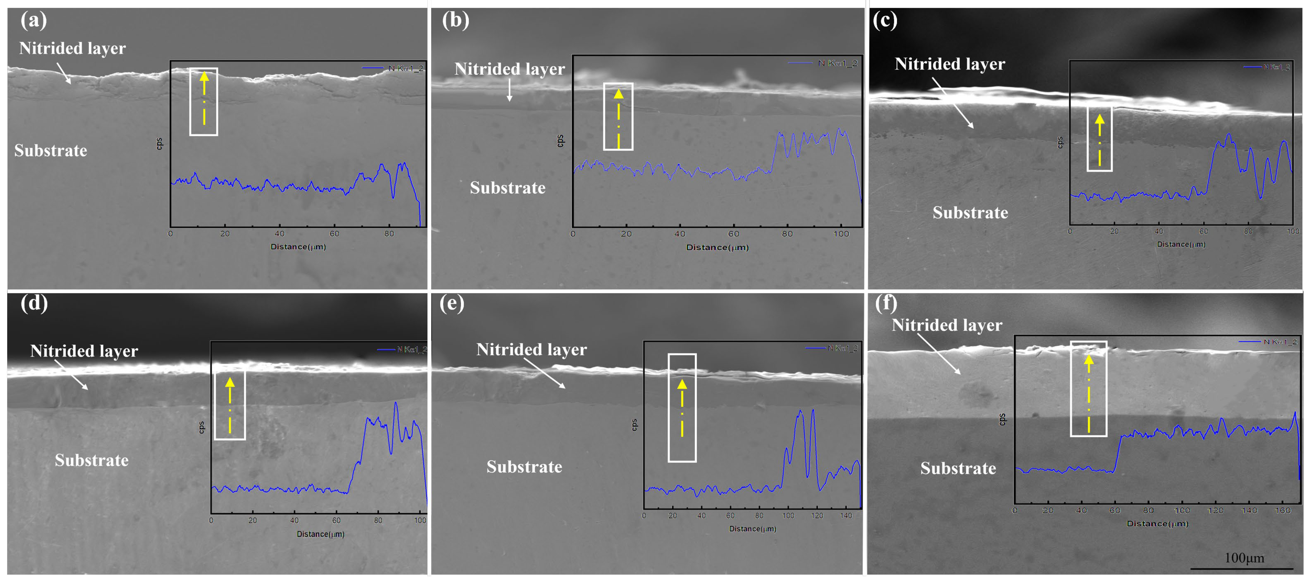
4.2. The Diffusion Behavior of Nitrogen Atoms During the Nitriding Process

Ion nitriding involves the process of continuous adsorption and diffusion of nitrogen ions. Nitrogen ions, generated through ionization, are accelerated by an electric field and continuously bombard the surface of the cathode specimen. The metal atoms that are sputtered by these nitrogen ions combine with the nitrogen ions to form nitrides [21], which are subsequently adsorbed on the specimen’s surface through scattering. As the surface-substable nitrides gradually decompose, active nitrogen atoms are released and diffuse into the specimen. Research has consistently been devoted to the nitriding of stainless steel in order to thicken the nitrided layer while upholding the corrosion resistance of austenitic stainless steel. According to the Arrhenius equation for the diffusion coefficient, there are two primary methods to improve the diffusion coefficient: lowering the activation energy of diffusion or increasing the nitriding temperature. It is well established that these two approaches can effectively increase the diffusion coefficient, as described by the Arrhenius diffusion coefficient equation.
The thickness of the penetration layer in the 316L austenitic stainless steel was measured under various deformation conditions, with the average thicknesses calculated as 28.57 μm, 32.14 μm, 35.17 μm, 37.5 μm, 44.64 μm, and 66.67 μm for 0, 10%, 20%, 30%, 40%, and 50% deformations, respectively. The results indicated that, compared to the nitrided specimens alone, the thicknesses of the penetration layers in the nitrided specimens significantly increased after deformation. Specifically, the depth of the nitrided layer without deformation was the thinnest, at 28.57 μm, followed by the nitrided sample with 10% deformation at 32.14 μm. The thicknesses of the nitrided layers with 20% and 30% deformation were similar, while the nitrided layer with 50% deformation exhibited the greatest thickness at 66.67 μm. As the deformation variable increased, the diffusion coefficient of the nitrogen atoms also increased, leading to a higher diffusion rate and a thicker penetration layer. When the morphology variable ranged from 0 to 50%, the thicknesses of the penetration layers increased from 28.57 μm to 66.67 μm. However, in the original austenitic matrix, the grain boundary corrosion of the six groups of specimens with different morphology variables resulted in the penetration layer being corroded to a black color. This observation indicates that iontophoresis negatively affects the corrosion resistance of the penetration layer in 316L austenitic stainless steel [22].
To further investigate the influence of various shape variables on the diffusion behavior of nitrogen atoms throughout the ion nitriding process of 316L stainless steel, the cross-sectional morphology of the infiltration layer was characterized using a SEM and EDS line scanning. Figure 9 presents the EDS analysis results for nitrogen (N) in the cross-section of nitrided 316L stainless steel specimens with different morphological variables, along with the corresponding SEM images of the line scanning area and cross-section. The line scan began in the matrix region and concluded in the infiltration layer region. As presented in Figure 9, the N element concentration is relatively stable at the beginning, and there is a peak value of N element on the exterior of the nitrided layer of the specimens with different morphology variables, and the concentration of the N element in the swept area of the specimen cross-section gradually rises along the direction from inside to outside, forming a N concentration gradient [23]. According to the cross-section, N element concentration changes can be introduced to the thickness of the penetration layer, that is, the larger the deformation variable, the wider the N element distribution area, the thicker the penetration layer, in line with the results observed under the metallurgical microscope. This indicates that deformation can enhance the diffusion of nitrogen atoms, increase the nitriding speed, and promote the growth of the thickness of the infiltration layer.
This phenomenon occurs because, during the deformation process, 316L austenitic stainless steel undergoes a martensitic transformation. Martensite possesses a BCC (body-centered cubic) or BCT (body-centered tetragonal) lattice structure, which is less densely packed compared to the FCC (face-centered cubic) lattice of austenite [24]. As a result, nitrogen atoms exhibit a lower diffusion activation energy in martensite, facilitating their movement within the stainless steel matrix. Furthermore, martensite tends to nucleate at defects such as dislocations, and its internal structure contains numerous structural imperfections [25]. Nitrogen atoms also diffuse along dislocations, which are relatively open structures. Consequently, the frequency of atomic jumps along these defects is higher than that of diffusion within the lattice. Thus, dislocations serve as channels for atomic diffusion, further reducing the diffusion activation energy of nitrogen atoms in martensite. In summary, the presence of structural defects, such as dislocations, along with the formation of martensite, both contribute to lowering the diffusion activation energy of nitrogen atoms in the material, thereby accelerating their diffusion rate.

5. Conclusions

In this paper, we investigate the low-temperature ion nitriding surface strengthening process of AISI 316L austenitic stainless steel, which shows promising application prospects. We employ a dual strategy of deformation treatment and low-temperature nitriding to explore the effects of defect density, grain boundary density, and changes in the second phase on the nitriding effectiveness of 316L stainless steel which has been subjected to various deformation variables. Additionally, we examine the related impact on hardness. The results are summarized as follows:
1. The deformation of 316L stainless steel at room temperature results in the formation of a significant number of dislocations, lamellae, martensite, and other microstructures. At a deformation level of 10%, the microstructural changes within the 316L stainless steel matrix are predominantly characterized by the presence of martensite and twin structures. As the deformation increases to 30% or more, the material exhibits a considerable number of structural defects within its microstructure.
2. Under identical nitriding temperatures, as the amount of deformation increases, the content of deformation-induced martensite in 316L stainless steel also increases. The formation of deformation-induced martensite is associated with the generation of dislocations and other structural defects, which hinder the migration of dislocations. This phenomenon enhances the strength of the intergranular deformation structure and contributes to an improvement in surface hardness.
3. The deformation treatment of 316L results in the formation of dislocations, laminar faults, grain boundaries, martensite, and other microstructural features. These structures, along with the interaction between dislocations and nitrogen atoms, facilitate the spread of nitrogen atoms. Consequently, this process enhances the growth of the penetration layer thickness during the low-temperature nitriding of 316L stainless steel and improves the hardness of this layer. However, this process concurrently leads to a reduction in the corrosion resistance of the permeate layer. One can observe that the thickness of the penetration layer increases with morphological changes and, similarly, the hardness of the penetration layer also increases with the enhancement of morphology. Conversely, the corrosion resistance of the nitrided layer diminishes with an increase in morphology.

Author Contributions

Conceptualization, K.S.; data curation, X.Z. and L.Z.; formal analysis, X.Z. and C.M.; investigation, X.Z., L.Z., C.M., and K.S.; methodology, X.H.; writing—original draft, X.Z.; writing—review and editing, X.Z., L.Z., C.M., X.H., and K.S. All authors have read and agreed to the published version of the manuscript.

Funding

This research received no external funding.

Institutional Review Board Statement

Not applicable.

Informed Consent Statement

Not applicable.

Data Availability Statement

Date are contained within the article.

Conflicts of Interest

The authors declare no conflicts of interest.

Abbreviations

The following abbreviations are used in this manuscript:
SEMScanning electron microscope
EBSDElectron backscatter diffraction
EDSEnergy-dispersive X-ray spectroscopy
XRDX-ray diffraction
BCCBody-centered cubic
BCTBody-centered tetragonal
FCCFace-centered cubic
KAMKernel Average Misorientation

References

  1. Bielawski, J.; Baranowska, J.; Szczecinski, K. Microstructure and properties of layers on chromium steel. Surf. Coat. Technol. 2006, 200, 6572–6577. [Google Scholar] [CrossRef]
  2. Manova, D.; Gerlach, J.; Scholze, F.; Mändl, S.; Neumann, H. Nitriding of austenitic stainless steel by pulsed low energy ion implantation. Surf. Coat. Technol. 2010, 204, 2919–2922. [Google Scholar] [CrossRef]
  3. Yang, W.J.; Zhang, M.; Zhao, Y.H.; Shen, M.L.; Lei, H.; Xu, L.; Xiao, J.Q.; Gong, J.; Yu, B.H.; Sun, C. Enhancement of mechanical property and corrosion resistance of 316 L stainless steels by low temperature arc plasma nitriding. Surf. Coat. Technol. 2016, 298, 64–72. [Google Scholar] [CrossRef]
  4. Ichimura, S.; Takashima, S.; Tsuru, I.; Ohkubo, D.; Matsuo, H.; Goto, M. Application and evaluation of nitriding treatment using active screen plasma. Surf. Coat. Technol. 2019, 374, 210–221. [Google Scholar] [CrossRef]
  5. Hoshiyama, Y.; Mizobata, R.; Miyake, H. Mechanical properties of austenitic stainless steel treated by active screen plasma nitriding. Surf. Coat. Technol. 2016, 307, 1041–1044. [Google Scholar] [CrossRef]
  6. Rocha, M.R.; Oliveira, C.A.S. Evaluation of the martensitic transformations in austenitic stainless steels. Mater. Sci. Eng. A 2009, 517, 281–285. [Google Scholar] [CrossRef]
  7. Cao, B.; Iwamoto, T.; Bhattacharjee, P.P. An experimental study on strain-induced martensitic transformation behavior in SUS304 austenitic stainless steel during higher strain rate deformation by continuous evaluation of relative magnetic permeability. Mater. Sci. Eng. A 2020, 774, 138927. [Google Scholar] [CrossRef]
  8. Zhang, R.H.; Yang, C.; Shi, N.; Guan, Y.; Ma, J.; Zhang, Y.; Chen, L. Research progress in plastic deformation characteristics of high nitrogen austenitic steel. Mater. Rep. 2021, 35, 11155. [Google Scholar]
  9. GB/T 7314-2017; Metallic Materials—Compression Test Method at Room Temperature. Standardization Administration of China: Beijing, China; China Standards Press: Beijing, China, 2017.
  10. Kaoumi, K.; Liu, J. Deformation induced martensitic transformation in 304 austenitic stainless steel: In-situ vs. ex-situ transmission electron microscopy characterization. Mater. Sci. Eng. A 2018, 715, 73–82. [Google Scholar] [CrossRef]
  11. Li, G.; Peng, Q.; Li, C.; Wang, Y.; Gao, J.; Chen, S.-Y.; Wang, J.; Shen, B.-L. Effect of DC plasma nitriding temperature on microstructure and dry-sliding wear properties of 316L stainless steel. Surf. Coat. Technol. 2008, 202, 2749–2754. [Google Scholar] [CrossRef]
  12. Fossati, A.; Borgioli, F.; Galvanetto, E.; Bacci, T. Glow-discharge nitriding of AISI 316L austenitic stainless steel: Influence of treatment time. Surf. Coat. Technol. 2006, 200, 3511–3517. [Google Scholar] [CrossRef]
  13. Wang, B.; Hong, C.; Winther, G.; Christiansen, T.L.; Somers, M.A. Deformation mechanisms in meta-stable and nitrogen-stabilized austenitic stainless steel during severe surface deformation. Materialia 2020, 12, 100751. [Google Scholar] [CrossRef]
  14. Liu, Y.; Jiang, Y.; Zhou, R.; Feng, J. Mechanical properties and electronic structures of M23C6 (M= Fe, Cr, Mn)-type multicomponent carbides. J. Alloys Compd. 2015, 648, 874–880. [Google Scholar] [CrossRef]
  15. Luiz, L.A.; Kurelo, B.C.E.S.; de Souza, G.B.; de Andrade, J.; Marino, C.E.B. Effect of nitrogen plasma immersion ion implantation on the corrosion protection mechanisms of different stainless steels. Mater. Today Commun. 2021, 28, 102655. [Google Scholar] [CrossRef]
  16. Cheng, M.; He, P.; Lei, L.; Tan, X.; Wang, X.; Sun, Y.; Li, J.; Jiang, Y. Comparative studies on microstructure evolution and corrosion resistance of 304 and a newly developed high Mn and N austenitic stainless steel welded joints. Corros. Sci. 2021, 183, 109338. [Google Scholar] [CrossRef]
  17. Zhang, Z.L.; Bell, T. Structure and corrosion resistance of plasma nitrided stainless steel. Surf. Eng. 1985, 1, 131–136. [Google Scholar] [CrossRef]
  18. Zhang, P.C. Strain induced martensite behavior of 316L stainless steel subjected to warm deformation. Heat Treat. Met. 2019, 44, 44. [Google Scholar]
  19. Mandal, A.; Morankar, S.; Sen, M.; Samanta, S.; Singh, S.B.; Chakrabarti, D. A Descriptive Model on the Grain Size Dependence of Deformation and Martensitic Transformation in Austenitic Stainless Steel. Met. Mater. Trans. A 2020, 51, 3886–3905. [Google Scholar] [CrossRef]
  20. Das, A.; Tarafder, S. Experimental investigation on martensitic transformation and fracture morphologies of austenitic stainless steel. Int. J. Plast. 2009, 25, 2222–2247. [Google Scholar] [CrossRef]
  21. Tao, X.; Liu, X.; Matthews, A.; Leyland, A. The influence of stacking fault energy on plasticity mechanisms in triode-plasma nitrided austenitic stainless steels: Implications for the structure and stability of nitrogen-expanded austenite. Acta Mater. 2019, 164, 60–75. [Google Scholar] [CrossRef]
  22. Lei, M.K.; Zhu, X.M. In vitro corrosion resistance of plasma source ion nitrided austenitic stainless steels. Biomaterials 2001, 22, 641–647. [Google Scholar] [CrossRef] [PubMed]
  23. Weng, J.Y.; Dong, H.; Li, B.; Bao, X.Y.; Ning, X.Z. Effect of nitrogen content on microstructure and properties of high nitrogen CrMnMo austenitic stainless steel. Heat Treat. Met. 2020, 45, 160. [Google Scholar]
  24. Naghizadeh, M.; Mirzadeh, H. Modeling the kinetics of deformation-induced martensitic transformation in AISI 316 metastable austenitic stainless steel. Vacuum 2018, 157, 243–248. [Google Scholar] [CrossRef]
  25. Kundu, A.; Field, D.P.; Chakraborti, P.C. Effect of strain and strain rate on the development of deformation heterogeneity during tensile deformation of a solution annealed 304 LN austenitic stainless steel: An EBSD study. Mater. Sci. Eng. A 2020, 773, 138854. [Google Scholar] [CrossRef]
Figure 1. X-ray diffraction pattern and microstructure of AISI 316L austenitic stainless steel substrate.
Applsci 15 02352 g001
Figure 2. Metallographic characterization of 316L stainless steel with variations in geometric shapes: (a) 0; (b) 10%; (c) 20%; (d) 30%; (e) 40%; (f) 50%.
Applsci 15 02352 g002
Figure 3. The surface microhardness of different deformations of the plasma-nitrided samples.
Applsci 15 02352 g003
Figure 4. The Tafel polarization curves of different deformations of the plasma-nitrided samples.
Applsci 15 02352 g004
Figure 5. The X-ray diffraction patterns of 316L stainless steel under varying morphological conditions.
Applsci 15 02352 g005
Figure 6. The KAM diagram of 316L stainless steel at different deformation levels: (a) 10%; (b) 20%; (c) 30%; (d) 40%; and (e) 50%.
Applsci 15 02352 g006
Figure 7. Image quality maps and grain size distributions of 316L stainless steel at different deformation levels: (a) 10%; (b) 20%; (c) 30%; (d) 40%; and (e) 50%.
Applsci 15 02352 g007
Figure 8. Phase distribution maps and orientation distribution maps of 316L stainless steel samples at different deformation levels: (a) 10%; (b) 20%; (c) 30%; (d) 40%; and (e) 50%.
Applsci 15 02352 g008
Figure 9. Nitrogen EDS change (The direction of the arrow is the direction of the line scan) of 316L stainless steel plasma-nitrided layer under different deformations (a) 0; (b) 10%; (c) 20%; (d) 30%; (e) 40%; (f) 50%.
Applsci 15 02352 g009
Table 1. Chemical composition of 316L austenitic stainless steel wt.%.
SiMnNiCrMoFe
≤1.00≤2.00≤10.00~14.0016.00~18.52.00~3.00Balance
Table 2. Parameters of low-temperature plasma nitriding process.
Temperature (°C)Pressure (Pa)Time (min)P (H2):P (N2)Voltage (V)
500300–40010004:3500–600
Table 3. Self-corrosion potential (Ecorr) and self-corrosion current density (icorr) of nitriding specimens of 316L stainless steel with different shape variables.
SampleEcorr/Vicorr/A.cm−2
Substrate−0.3038.913 × 10−7
0−0.255.687 × 10−6
10%−0.258.769 × 10−6
20%−0.2728.18 × 10−7
30%−0.2899.183 × 10−7
40%−0.2712.164 × 10−6
50%−0.2611.1007 × 10−6
Disclaimer/Publisher’s Note: The statements, opinions and data contained in all publications are solely those of the individual author(s) and contributor(s) and not of MDPI and/or the editor(s). MDPI and/or the editor(s) disclaim responsibility for any injury to people or property resulting from any ideas, methods, instructions or products referred to in the content.

