1. Introduction
The rising global demand for marine resources and enhanced transportation capabilities has driven extensive research into innovative materials specifically tailored for marine applications, including platforms, pipelines, and essential connection components. These developments aim to address the unique challenges of the marine environment, ensuring the reliability and longevity of critical infrastructure. The corrosion of metals remains a major concern across diverse sectors, affecting not only the structural integrity and lifespan of materials, but also posing environmental hazards by introducing contaminants into ecosystems and creating potential health risks for workers. Among various types of corrosion, microbiologically influenced corrosion (MIC) stands out as a significant issue, particularly in aquatic environments [
1]. MIC results from the activity of microorganisms that form biofilms on material surfaces, which alter the local electrochemical environment and accelerate corrosion through oxygen concentration gradients and differential aeration cells [
2,
3]. Additionally, microbial metabolic byproducts can further intensify material degradation, leading to faster structural failure [
4]. As MIC contributes to substantial economic losses worldwide, with corrosion costs representing a considerable portion of industrial maintenance budgets [
5], addressing MIC is critical. Effective management strategies not only extend the service life of assets, but also protect environmental and human health, making MIC mitigation a priority in corrosion science.
High-entropy alloys (HEAs), first conceptualized by Yeh et al. [
6], mark a paradigm shift in alloy design by incorporating multiple principal elements in near-equiatomic ratios. This unique composition confers a high configurational entropy, promoting single-phase solid solutions rather than complex intermetallics, which are typical in conventional alloys. Due to their distinctive microstructures, HEAs exhibit exceptional properties, such as enhanced hardness, wear resistance, and corrosion resistance, making them suitable for protective coatings in demanding environments like marine applications [
6,
7].
HEAs are generally classified into three main categories based on their phase structures: single-phase, multi-phase, and amorphous or nano-crystalline. Single-phase HEAs, which often adopt face-centered cubic (FCC), body-centered cubic (BCC), or hexagonal close-packed (HCP) structures, offer a balance between ductility and toughness, as shown in studies by Otto et al. [
7] and Zhang et al. [
8]. Multi-phase HEAs, on the other hand, can exhibit combined FCC and BCC phases, enhancing their strength and hardness due to phase boundary strengthening effects [
9]. Amorphous or nano-crystalline HEAs present high corrosion and wear resistance due to their lack of crystalline boundaries, which makes them particularly suitable for coating applications in marine environments [
8].
High-entropy alloy (HEA) coatings are gaining attention for their ability to enhance the corrosion resistance and durability of various metals, particularly under harsh conditions. While HEA coatings share the same fundamental composition principles as bulk HEAs, they involve distinct fabrication techniques suited for their thin-film structure [
10]. This structural difference not only influences mechanical properties but also alters failure mechanisms compared to bulk HEAs [
11,
12]. HEA coatings offer several benefits over bulk HEAs, particularly in reducing costs and improving practicality. Due to the complex composition of HEAs and the challenges of alloying elements with widely varying melting points, bulk HEAs often require extensive post-processing, making them costly to produce [
13,
14,
15]. HEA coatings, on the other hand, use less material and can be produced more economically using energy-efficient processes, making them more practical for industrial applications [
16].
The flexibility of HEA coating fabrication allows control over the coating properties—such as thickness, density, and surface quality—by adjusting process parameters like deposition temperature, laser power, and sputtering power. Additionally, HEA coatings are compatible with a range of substrates, including steel, aluminum alloys, magnesium alloys, and titanium alloys, providing uniform coverage and consistent performance even on complex shapes [
17,
18]. In terms of functionality, HEA coatings excel in environments requiring resistance to corrosion, erosion, and wear [
16]. This makes them suitable for challenging conditions, such as marine and extreme cold environments, as well as high-radiation and high-altitude applications. Overall, the versatility, economic benefits, and enhanced protective qualities of HEA coatings position them as a promising solution for extending the service life of metal substrates in demanding applications.
Additive manufacturing methods such as selective laser melting (SLM) have recently enabled the fabrication of complex high-entropy alloy (HEA) components, as highlighted by Guo et al. [
19], who demonstrated the machinability and enhanced mechanical properties of CoCrFeMnNi HEAs produced via SLM. However, challenges related to surface quality and subsequent processing remain significant, necessitating further investigation into alternative fabrication and processing techniques, such as sputtering and coating technologies.
The deposition of HEA coatings through direct current (DC) magnetron sputtering has proven advantageous for producing dense, uniform films with tailored properties. Magnetron sputtering involves bombarding a target with high-energy ions to eject atoms, which are then deposited as a thin film on the substrate. Studies by Kelly and Arnell [
20] provide an overview of sputtering technology, highlighting its benefits in achieving controlled thickness and composition in thin-film coatings. More recent work [
21] demonstrates that DC magnetron sputtering can precisely control the microstructure of HEA coatings, which is essential for optimizing their corrosion resistance in marine environments. Notably, researchers found that the dense microstructures achieved through sputtering inhibit the penetration of corrosive ions and exhibit superior stability in chloride exposure, common in marine applications. The limitation of this coating technique could be the poor uniformity on large and complex geometry substrates, but its good structural accuracy presents high interest for industry.
Marine materials, including carbon steels, stainless steels, and titanium, are highly susceptible to microbial colonization and biofilm development, which contribute to microbially influenced corrosion (MIC) and biofouling. To mitigate MIC, researchers have extensively explored incorporating antimicrobial elements, such as copper (Cu), into these materials [
22,
23]. Recent studies highlight the potential of copper (Cu) as a beneficial addition to HEA systems, especially for marine corrosion resistance. Copper can enhance passivation by promoting stable oxide layer formation on HEA surfaces, which is crucial for applications in chloride-rich marine environments. Shi et al. [
24] demonstrated that Cu-doped HEAs exhibit improved resistance to localized corrosion due to the protective passivation layer that Cu facilitates. Additionally, Yang et al. [
25] observed that Cu additions can significantly mitigate pitting corrosion, a common degradation mode in saline conditions, thus extending the alloy’s service life in harsh environments.
High-entropy alloy (HEA) coatings present a promising solution for such applications due to their customizable composition and ability to incorporate elements with antimicrobial properties. HEA coatings not only improve the corrosion resistance of substrates but also allow the integration of elements like Cu, which can effectively reduce microbial adhesion and biofilm formation. This makes HEA coatings particularly suitable for marine environments, where they provide enhanced durability and protection against microbial-induced degradation, extending the service life of marine structures.
In this study, two CuCrFeMnNi-type alloys containing 5 wt. % and 10 wt. % Cu were used as targets for the deposition of coatings via DC magnetron sputtering using a glow discharge system, with sputtering power as the variable parameter. The resulting HEA coatings were characterized both structurally, through scanning electron microscopy (SEM), X-ray diffraction (XRD) and atomic force microscopy (AFM), and functionally, using scratch testing and corrosion resistance evaluation in NaCl solution. To gain a comprehensive understanding of the coatings’ performance, structural analysis provided insight into the morphology and phase composition, while functional tests assessed adhesion strength and corrosion protection efficacy. This approach ensures a thorough evaluation of the HEA coatings’ suitability for applications requiring high durability and resistance to harsh environments.
2. Materials and Methods
2.1. Materials Preparation
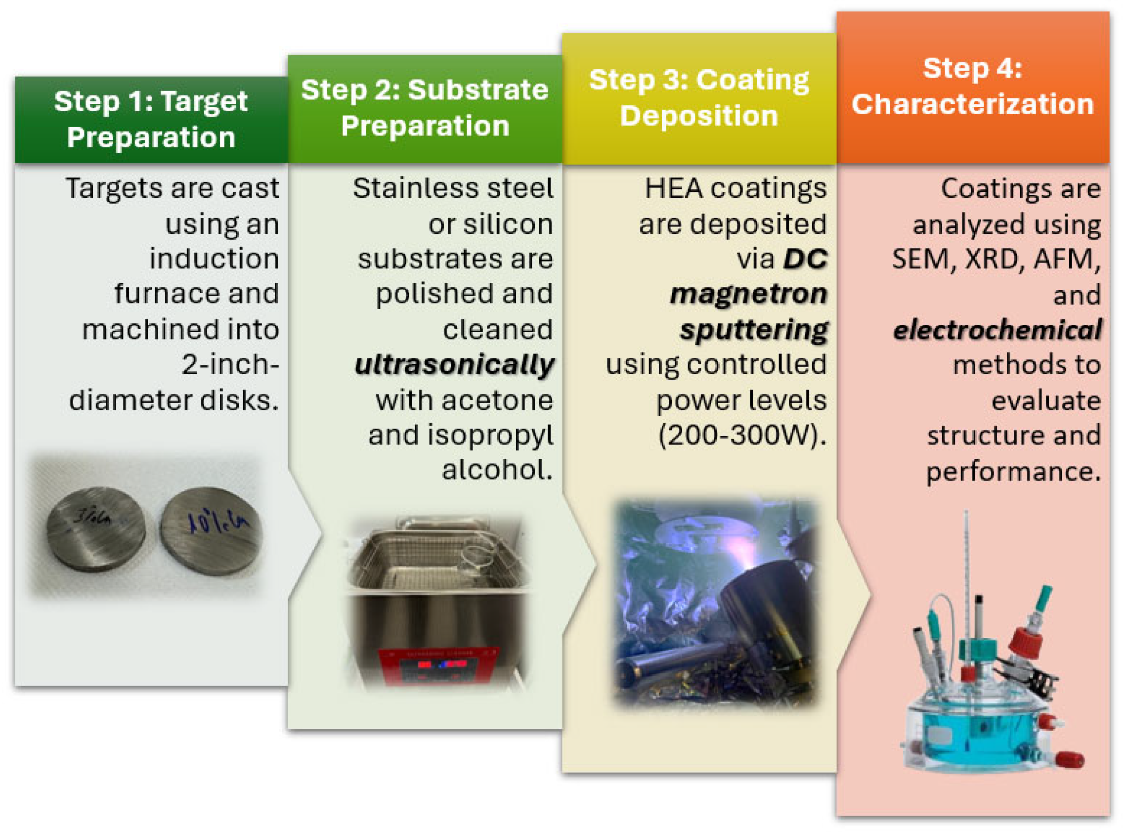
Two CuCrFeMnNi high-entropy alloys (HEAs) with 5 wt. % Cu (I8-6-T) and 10 wt. % Cu (I8-7-T) were selected as sputtering targets. The alloys were cast in an induction furnace and then machined into 2-inch-diameter targets.
The chemical composition of the cast ingots was determined by inductively coupled plasma optical emission spectrometry (ICP-OES) using an Agilent 725 spectrometer (Santa Clara, CA, USA) (
Table 1).
The HEA coatings were deposited using a DC magnetron sputtering method in a hybrid Physical Vapor Deposition (PVD) system (Torr, Auburn, WA, USA). The sputtering system was equipped with a Kurt J. Lesker 2-inch TORUS circular magnetron sputtering gun (Kurt J. Lesker, Jefferson Hills, PA, USA) and a PD500X direct current source (Kurt J. Lesker, Jefferson Hills, PA, USA) with a maximum power of 1500 W. Three deposition powers (200 W, 250 W, and 300 W) were applied for each HEA composition, resulting in a total of six coating batches, as presented in
Table 2.
Given that the sputtering power level significantly affects the coating thickness, it was opted to deposit at 200 W for 60 min and at 300 W for only 40 min, to achieve comparable coating thicknesses. Greater thickness can introduce other variables such as mechanical stress, cracks, poor adhesion, and the need for substrate heating.
The deposition of HEA samples for 40 min at 200 W generates thin layers, under 1 µm, and would be too small for structural characterization (EDS especially). So, a coating thickness of 1.5–2 µm thickness was targeted for all coating power levels.
Deposition rate is measured by dividing the total thickness of the coating with the time of deposition process. Prior to loading the samples, we made several coatings on silicon substrates and measured the obtained layer thickness with a profilometer; if, for example, we obtained 4 µm thickness layers in 120 min, then we know that if we deposit for 60 min in the same conditions, we will obtain 2 µm thickness.
Stainless steel 304L substrates (15 × 15 × 3 mm) were used for the main deposition, and additional silicon substrates were employed for the SEM-EDS analysis to avoid interference with the morphological and compositional results. The deposition parameters were selected to optimize the microstructure and adhesion of the coatings. The substrate surfaces were prepared by fine grade polishing and ultrasonic cleaning in acetone and isopropyl alcohol. The technological flow for the deposition of the HEA coatings is presented in
Figure 1.
2.2. Characterization Techniques
The morphological and elemental analyses of the coatings were performed using a Quanta 250 scanning electron microscope (FEI Company, Eindhoven, The Netherlands) operating at 15 kV, equipped with an EDAX energy-dispersive X-ray spectrometer (EDAX, Mahwah, NJ, USA) for semi-quantitative compositional assessment. To avoid interference from the substrate, samples for SEM-EDS analysis were prepared on silicon substrates.
The phase composition of the HEA coatings was analyzed using a Rigaku Ultima IV X-ray diffractometer (Rigaku Corporation, Akishima, Japan) equipped with parallel beam optics and a thin-film attachment. XRD scans were conducted over a 2θ range of 20–100° at a scanning speed of 2°/min with a step size of 0.02° and a fixed incidence angle (ω) of 0.5°. The Cu Kα radiation source (λ = 1.5405 Å) enabled detailed investigation of the crystalline phases and grain sizes in the deposited coatings.
The coatings adhesion was assessed using a NANOVEA Scratch Tester (NANOVEA, Irvine, CA, USA) system with a 120° conical indenter and a 50 µm tip. The indenter was applied with a load range of M0–M1250, measuring the critical load for coating delamination. The load of the indenter was progressive from 1 Newton to 10, with a 5 N/min loading rate for a distance of 5 mm.
Vickers microhardness was measured using a Wilson VH3100 (Wilson, Chicago, IL, USA) hardness tester with a 0.05 kgf load held for 30 s. Five indentations were averaged for both the coated stainless steel substrates and target alloys, allowing for a comparative analysis between 5% and 10% Cu HEA coatings.
The electrochemical corrosion studies were conducted at room temperature in an ASTM (American Society for Testing and Materials) corrosion cell with a volume of 1 L, equipped with a three-electrode setup: the working electrode, which was the material under analysis, with an exposed surface area of 1 cm
2; the reference electrode, an Ag/AgCl electrode in a 3 M KCl solution; and the counter electrode, a platinum wire. These three electrodes were connected to an Autolab PGSTAT 128N potentiostat/galvanostat (Methrom, Autolab Utrecht, The Netherlands) linked to a computer running NOVA v2.1 software. The electrolyte solution used was NaCl at a concentration of 3.5 g/L, in accordance with ASTM G61-86 standard (Reapproved 2003) [
26]. Experiments were carried out after a 60 min immersion period of the electrodes in the electrolyte solution. The working procedure for the experiments involved linear polarization, which included determining the open circuit potential (OCP) of the working electrode, followed by linear sweep voltammetry (LSV) with a stepped profile in the potential range of −0.1 V to +0.1 V relative to the open circuit potential, at a sweep rate of 0.001 V/s. Corrosion analysis was performed through the automatic determination of corrosion parameters, providing valuable insights into the material’s corrosion resistance under the specified test conditions.
An AFM characterization was conducted to obtain nanoscale topography of the coatings. These studies were performed by means of AFM (, Bruker Nano GmbH, Berlin, Germany) operating with an image resolution of 512 × 512 pixels. The images were collected in Quantitative Imaging (QI) mode, with pixel times of 6–18 ms for each pixel, using an Cr/Pt-coated silicon nitride cantilever (Multi75-G tip, Budget Sensors, Watsonville, CA, USA) with a nominal spring constant of 75 N m−1. The software JPK Data Processing v6.4 (JPK Instruments AG, Berlin, Germany) was used for offline analysis of the topography and the film roughness. Image flattening was performed with the first order, least-square polynomial function, which removes the tilt and the vertical z-offset between line scans.
3. Results and Discussion
The high-entropy alloy (HEA) coatings with 5 wt. % and 10 wt. % Cu were successfully deposited onto 304L stainless steel and silicon substrates using DC magnetron sputtering at varied power settings (200 W, 250 W, and 300 W).
3.1. SEM and EDS Analysis Results
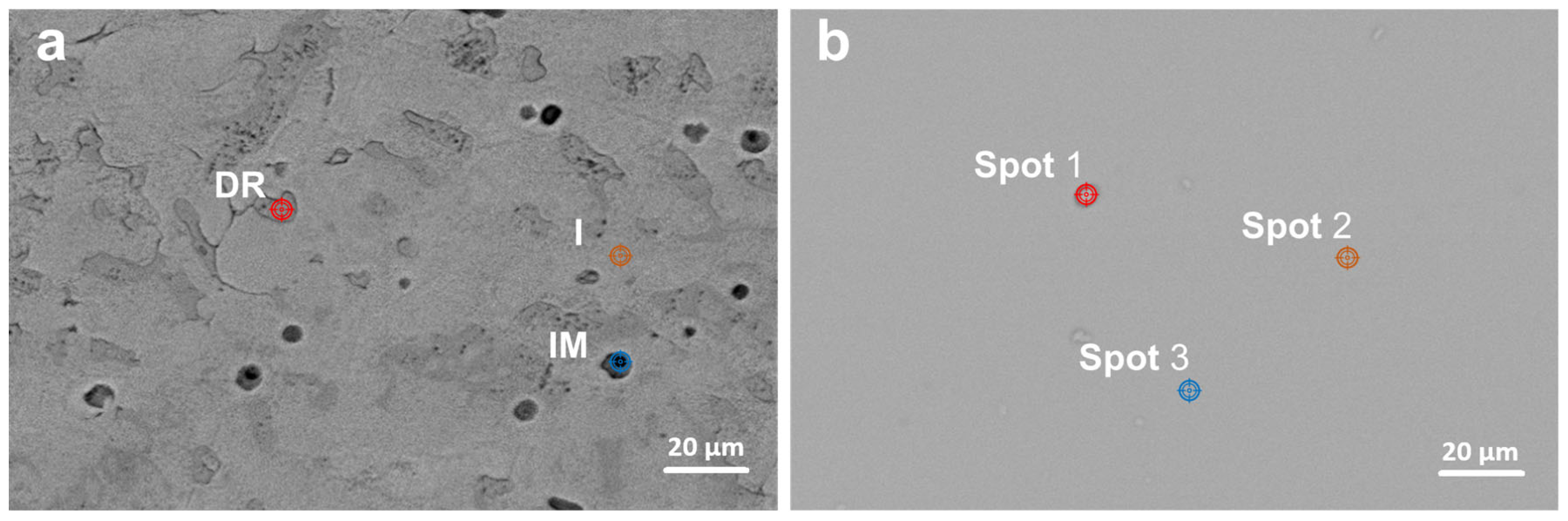
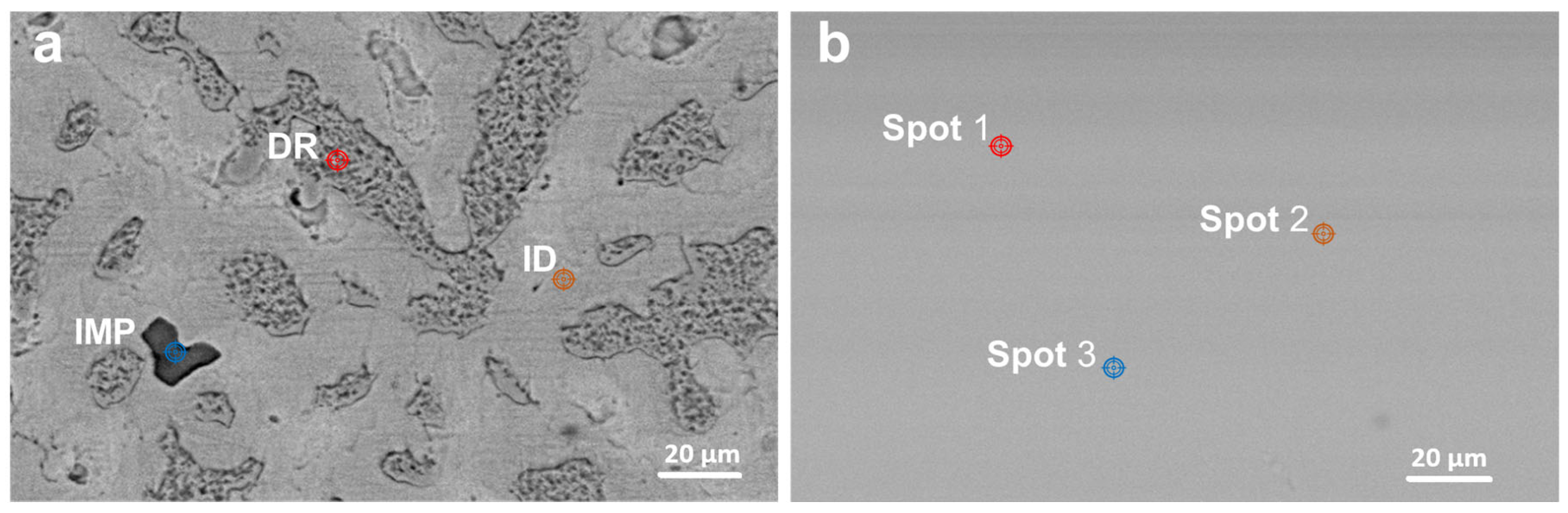
The microstructural characteristics of the HEA coatings with 5 wt. % and 10 wt. % Cu, deposited at different power settings, were examined using scanning electron microscopy (SEM) to assess morphology, surface uniformity, and deposition quality. First,
Figure 2 and
Figure 3 present SEM images of the HEA coatings, compared with the SEM images of the HEA targets. The as-cast samples present well defined interdendritic (ID) and dendritic phases (DR). Impurities are also found in the target structure (IMP). The deposited samples did not show an obvious phase structure compared to the as-cast targets.
Semi-quantitative spot EDS analysis results (
Table 3) confirmed the presence of Cr, Mn, Fe, Ni, and Cu, consistent with the composition of the alloy targets determined by ICP-OES spectroscopy (
Table 1). The as-cast samples contain two major phases (DR and ID) with concentrations varying mainly by the Mn and Ni content. The thin film coatings displayed a homogeneous distribution of elements, closely matching the target composition, with only minor variations.
The most notable differences were observed in the concentration of Mn and Ni, versus the actual target concentration. This can be attributed to their differential sputtering yields and deposition rates, which may lead to slight variations in the final elemental distribution on the coating surface. The sensitivity of Mn and Ni to sputtering yields and deposition rates is driven by:
Atomic properties like binding energy and mass.
The sputtering yield being dependent on the mass ratio between the incident ion (e.g., Ar) and the target atoms. Mn, being lighter than many other alloy constituents, is more easily ejected, while Ni, being intermediate in mass, is also moderately affected.
Mn, being relatively light compared to many transition metals, being preferentially sputtered. This occurs because lighter elements require less momentum transfer to overcome their binding energy.
Mn having a relatively higher vapor pressure compared to Ni and many other elements in high-entropy alloys (HEAs). This means that Mn is more likely to evaporate or redistribute during deposition, leading to fluctuations in its deposition rate.
Ni atoms, due to their intermediate mass and relatively high binding energy, may undergo more re-deposition, where sputtered atoms are redeposited back onto the target or substrate.
Cascade and energy transfer mechanisms during sputtering.
These factors collectively make Mn and Ni more prone to compositional variations in sputtering-based thin film deposition processes.
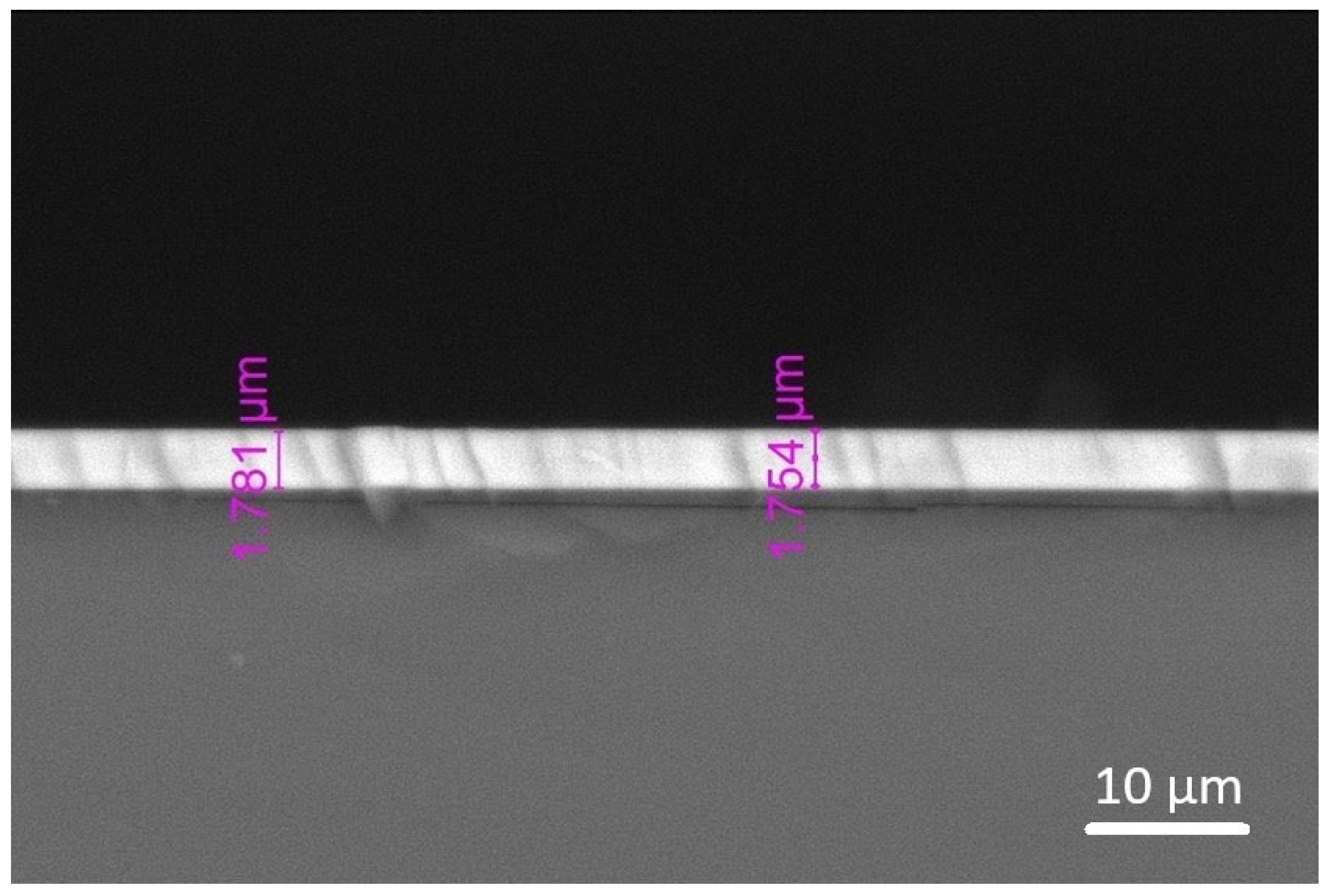
Overall, the coatings exhibited dense, uniform surfaces with an even thickness and strong adhesion to the substrates, as evidenced by the cross-sectional SEM image (
Figure 4) that shows an absence of significant voids, cracks, or signs of delamination. An improved adhesion is crucial for maintaining the coatings’ integrity under operational stresses, suggesting effective bonding achieved through the controlled deposition process. The increase in the deposition power achieved similar coating thickness between the two HEA targets, suggesting that the Cu content has less effect on thickness as power increases (
Table 4). The deposition power of 300 W seems to be the optimal value, having the fastest deposition rate of 37 nm/min, and similar thickness obtained regardless of the Cu content of the target.
3.2. X-Ray Diffraction Results
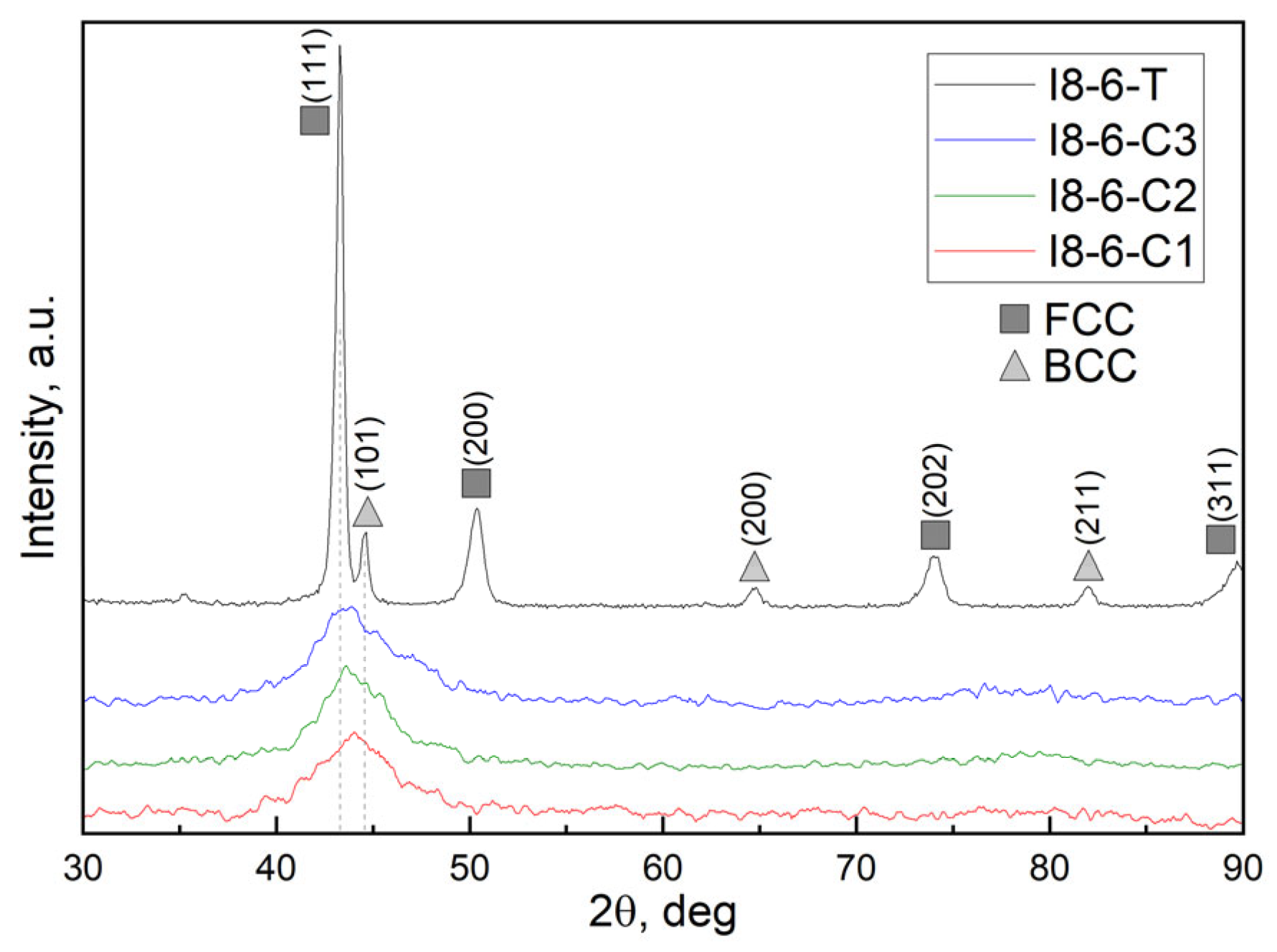
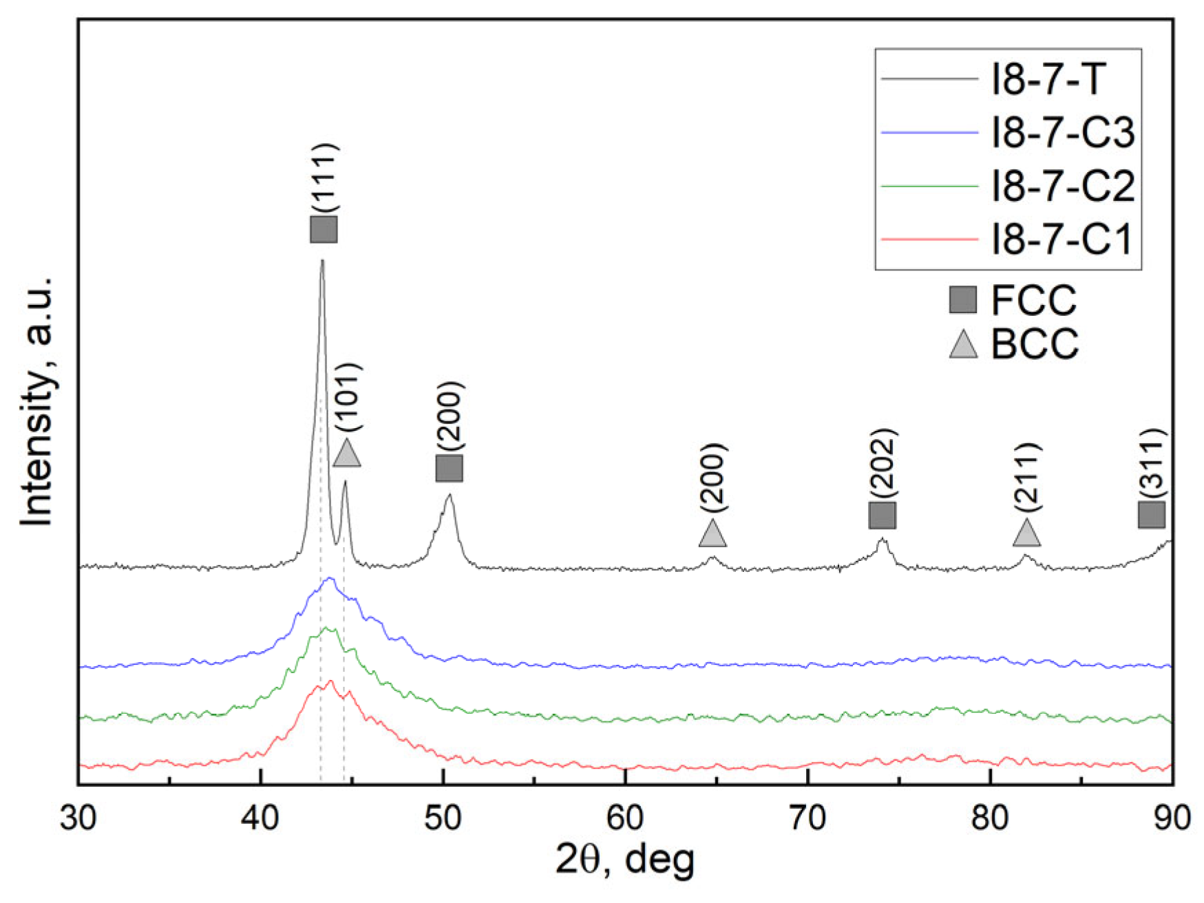
Results of the XRD analysis for CuCrFeMnNi HEA coatings along with the as-cast HEAs used as targets for magnetron sputtering are shown in
Figure 5 (for 5 wt. % Cu HEAs) and
Figure 6 (for 10 wt. % Cu HEAs). XRD patterns of as-cast alloys reveal the presence of two phases, identified as the main FCC and secondary BCC structures. This corresponds with the findings from SEM analysis of the bulk alloys shown in
Figure 2 and
Figure 3. Coupling it with the EDS analysis, one may conclude that as-cast HEAs consist of a dendritic BCC phase and interdendritic FCC phase. The higher intensity ratio of the FCC phase in the HEA-5Cu sample may suggest its higher fraction in this sample compared to the HEA-10Cu alloy.
Both figures with XRD patterns of as-deposited coatings demonstrate low-intensity broad peaks with a maximum around 2Theta = 43.5 deg, which can potentially be attributed to the (111) plane of a cubic structure, indicating a consistent phase across all samples. In the case of HEA-5%Cu magnetron sputtering, a slight shift to lower 2Theta values is observed with an increase in magnetron power from 200 to 250 and 300 W (
Figure 5). Across all samples, no other XRD pattern evolutions were observed with an increase in magnetron sputtering power.
Overall, such broad peaks on the XRD patterns of complex compositional alloys can indicate an amorphous structure, a low degree of crystallinity, or nanocrystalline structure, likely due to high cooling rates during deposition. Peak broadening may be also caused by sever lattice distortion, commonly occurring in HEAs.
3.3. Atomic Force Microscopy Results
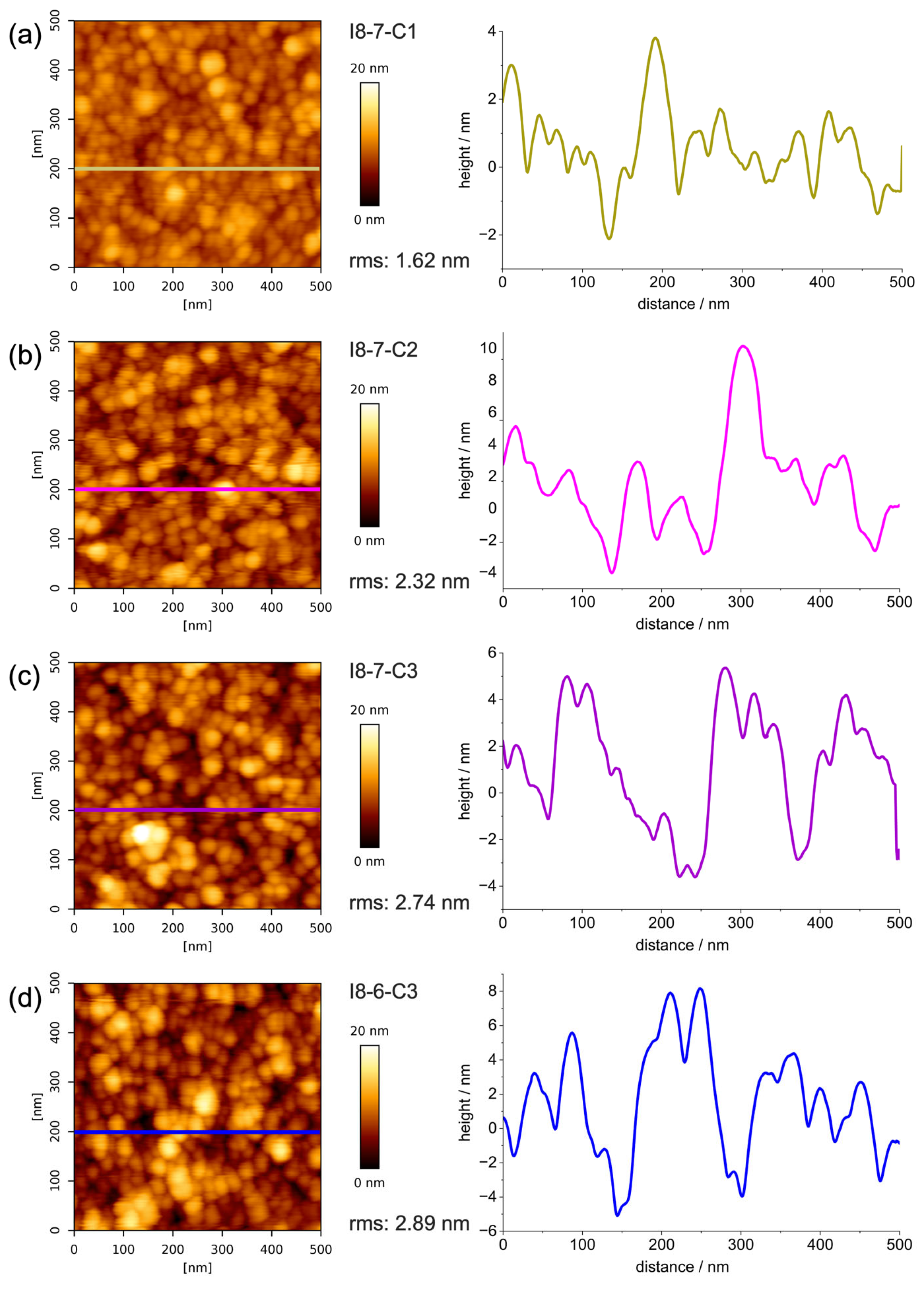
Figure 7a–c illustrate the topography and corresponding height profile of HEA coatings with a higher Cu content (I8-7, 10% Cu), characterized as having the highest corrosion resistance compared to coatings with lower Cu content (I8-6, 5% Cu). The surface morphology, evaluated using atomic force microscopy (AFM), reveals a homogeneous granular structure across all samples, with distinct variations in roughness depending on the deposition power during the sputtering process. The coating deposited at 200 W exhibits the smoothest surface, with a root mean square roughness (RMS) value of 1.62 nm. This smoothness is attributed to the lower deposition rate, which allows for an adequate surface diffusion of atoms, promoting finer grain structures and reducing void formation.
In contrast, the coating deposited at 250 W displays a slightly higher rms value of 2.32 nm, while the coating produced at 300 W demonstrates the highest roughness, with a rms value of 2.74 nm. The increased deposition power at 300 W results in a higher deposition rate, which accelerates the accumulation of atoms on the substrate, limiting the time available for atomic rearrangement and leading to the formation of larger grains and more pronounced voids between them. Coatings deposited from I8-6 (5% Cu) and I8-7 (10% Cu) HEA targets demonstrate similar topography and comparable granular size and roughness when considering the same applied magnetron sputtering power, as seen from the comparison in
Figure 7c,d.
All coatings exhibited a granular structure on AFM images, which is in line with the previously discussed obtained XRD results, suggesting that deposited films have a nanocrystalline structure. It is also seen that with the increase in the sputtering power, the size of the grains on the surface slightly increases. It is important to mention that the deposition time of the coatings at 300 W was 33% shorter than the ones deposited at 200 W, and the resulting thickness is 15–25% lower, respectively.
3.4. Adhesion Evaluation by Scratch Test
The adhesion of the coating on the 304L steel substrate was assessed through a scratch test to determine the coating’s bonding strength and resistance to mechanical stress. Usually, the scratch test results indicate that the critical normal force required to initiate indentation rises as the hardness of the substrate increases, demonstrating that harder substrates offer more resistance to deformation under applied loads. Additionally, the critical load necessary to cause detachment of the coating from the substrate increases with the thickness of the deposited film, suggesting that a thicker coating layer enhances adhesion resilience under mechanical stress.
Notably, in this work, along the scratch path for the HEA coatings (
Figure 8), there is no visible detachment of the HEA coating from the 304L steel substrate, indicating the excellent adhesion and mechanical integrity of the coating. This strong adhesion across both deposition materials suggests that the HEA coating forms a robust interface with the substrate, contributing to its durability and potential suitability for applications requiring high wear resistance. No significant differences were observed between the layer deposited at various power values and Cu percentage.
3.5. Microhardness Measurement Results
To evaluate the mechanical performance of the coatings, the hardness was measured with a constant load of 0.05 kgf and a corresponding holding time of 30 s. Each Vickers hardness value was obtained by averaging five indentation tests on the HEA coatings on stainless steel substrate. The values obtained are shown in
Table 5.
The Vickers hardness results, presented in
Table 5, demonstrate the mechanical performance of the Cu-enhanced high-entropy alloy (HEA) coatings applied to stainless steel 304L. The uncoated stainless steel 304L exhibited a hardness of 318.8 HV. When coated with I8-6, the hardness increased to 331.8 HV, while the I8-7 coating showed a slightly lower hardness of 331.3 HV. These results suggest that the introduction of Cu into the HEA coatings improves the hardness of the stainless steel substrate, with I8-6 coating providing a modest improvement over the uncoated material. The slight reduction in hardness observed for the I8-7 coating may indicate a change in the coating’s microstructure or phase composition, which requires further investigation. Nevertheless, both Cu-enhanced coatings provide improved hardness compared to the uncoated substrate, suggesting better wear resistance and mechanical durability, which are critical for applications where surface performance is crucial.
3.6. Electrochemical Corrosion Results
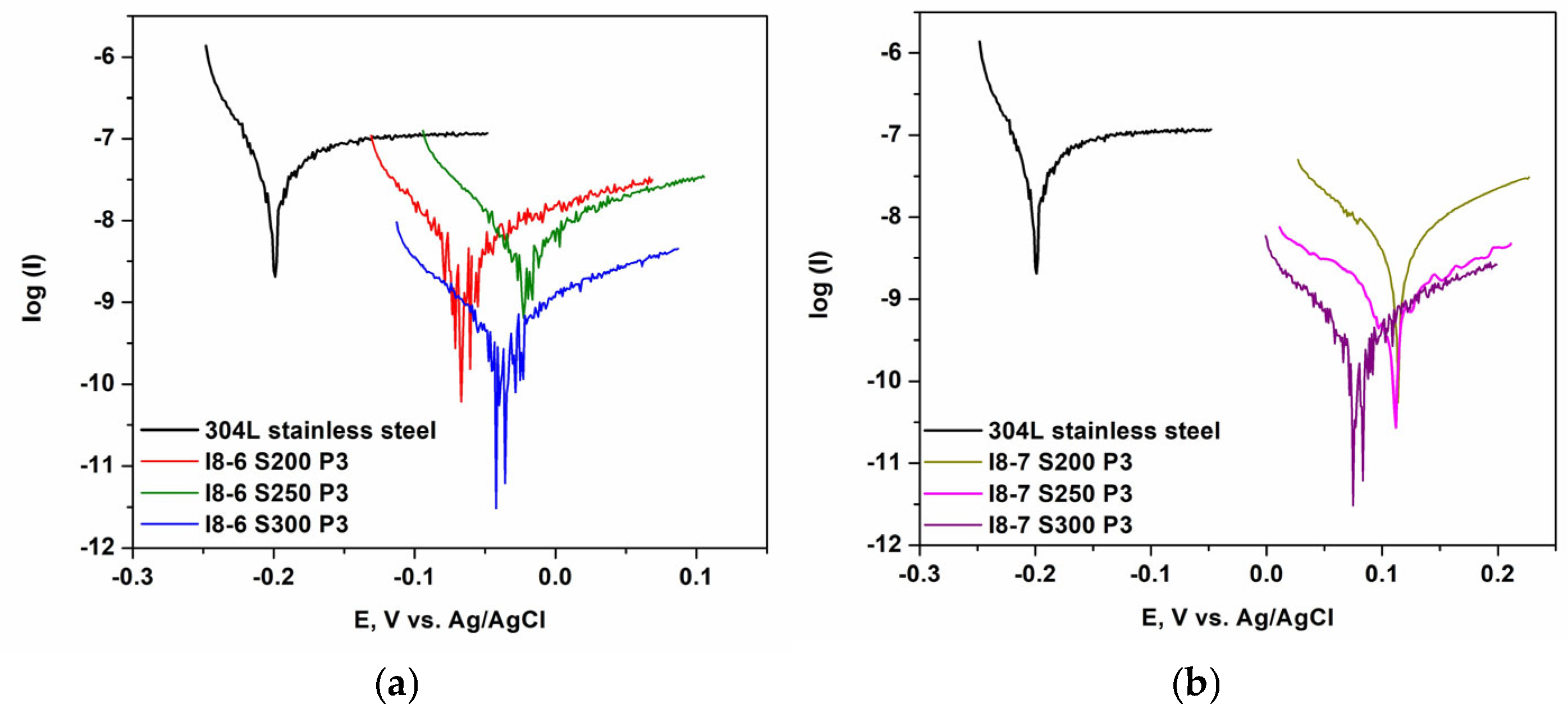
The results obtained for the two types of HEA coatings (I8-6 with 5% Cu and I8-7 with 10% Cu) compared to the uncoated substrate (304L stainless steel) and to HEA ingots are presented in
Table 6 and
Figure 9. As shown in
Table 6, HEA-based coatings with 10% Cu content improve the corrosion resistance of 304L steel in NaCl solutions at a concentration of 3.5 g/L. The sample I8-7 S300, produced from HEA ingots with 10% Cu at 300 W power, demonstrates the lowest corrosion rate (9.67 nm/year) and the highest polarization resistance (31.31 MΩ). It is also evident that the HEA coatings on 304L steel exhibit greater corrosion resistance compared to the alloys from which they were derived. The coating films deposited at 300 W achieved the best values, suggesting that the deposition power level has a bigger influence on the corrosion resistance than the difference in the Cu content of the coatings. However, at 300 W power a higher Cu content significantly improves the corrosion resistance compared to 5% Cu.


 ,
, 


