Article

Single-Glazed Vacuum Tube Collector with SnAl2O3 Selective Flat Absorber Plate and Gravity Single-Stage Direct Water Flow: A Comprehensive Geometric Optimization

by
Aleksandar Nešović
1 and
Robert Kowalik
2,*
1
Institute for Information Technologies, University of Kragujevac, Jovana Cvijića bb, 34000 Kragujevac, Serbia
2
Faculty of Environmental Engineering, Geodesy and Renewable Energy, Kielce University of Technology, Tysiaclecia P.P. 7, 25-314 Kielce, Poland
*
Author to whom correspondence should be addressed.
Appl. Sci. 2025, 15(4), 1838; https://doi.org/10.3390/app15041838
Submission received: 22 December 2024 / Revised: 29 January 2025 / Accepted: 3 February 2025 / Published: 11 February 2025
(This article belongs to the Special Issue Solar Energy Collection, Conversion and Utilization)

Abstract

:
This paper continues the mathematical research of the novel glass tube collectors for water heating. The subject of this research is a vacuum solar collector composed of a glass tube and a selective (using the SnAl2O3 coating) flat absorber plate. Water heating is performed using gravitational driving force and single-stage direct flow. The thermal performance with the geometric optimization (absorber width and glass tube thickness) of the presented solar collector type was determined using the specially designed iterative calculation algorithm (phase 1) and the double multi-criteria analysis (phase 2). Different operational (absorber temperature, ambient temperature and wind speed), geometric (mass, surface occupation, total surface occupation and volume occupation), economic (manufacturing costs and exploitation costs) and ecological (embodied energy and greenhouse gas emission) indicators were taken into account. The results showed that the useful heat power has an increasing trend if the flat absorber plate width increases, while the thermal efficiency has a decreasing trend. It was also determined that the glass tube thickness and the thermal performance of the solar collector are oppositely dependent. The main conclusion of this paper is that the optimal performance of such non-conventional solar systems is achieved when the absorber plate width is between 85 and 90 mm.

1. Introduction

Advancements in solar technology and solar physics are essential for the share of solar energy in the total RES mix to increase in the future. This includes improving existing solar devices and inventing new ones [1]. These innovations must enhance useful heat power and thermal efficiency while maintaining economic affordability.
The traditional classification, according to which solar collectors (SCs) can be non-tracking, i.e., fixed or tracking (first classification criteria [2,3,4]) and non-concentrating or concentrating (second classification criteria [5,6,7]), is considered obsolete today. This is best illustrated by modified versions of flat-plate collectors (FPCs) and evacuated tube collectors (ETCs)—SCs that are traditionally fixed and non-concentrating.
FPCs and ETCs are characterized by small dimensions [8], relatively simple manufacturing technologies [9], low production and sales costs (market availability [10]) and satisfactory thermal performance (FPCs’ and ETCs’ zero-loss thermal efficiencies are about 80% and 70%, respectively [11]). In other words, these are solar structures with an excellent basis for further improvements, which can be achieved with simple technological solutions and low investments. Table 1 shows some modified solutions (with an emphasis on reflectors and tracking mechanisms) implemented in the past using mathematical (math), numerical (num) and experimental (exp) scientific approaches.
For instance, Ditta et al. [31] investigated a hybrid ETC configuration, achieving the maximum outlet temperature of 87 °C, thermal efficiency of 56% and cooling capacity of 4.6 kW. Supankanok et al. [32] developed an ETC with a modified design, achieving a heat transfer fluid temperature of 160.32–22 °C higher than standard tubes. Other studies, such as those by Ma et al. [33] and Kaya et al. [34], explored advanced designs and working fluids, including nanofluids, to enhance performance. Kaya et al. reported the highest collector efficiency at 68.7%, using the 4.0 vol% Ag/EG-PW nanofluid.
The measurement and simulation of the flow rate in the water-in-glass ETC were realized by Morrison et al. in [35]. The natural circulation flow through the water-in-glass ETC with the flat reflector behind (and parallel) was investigated numerically and experimentally in [36]. The theoretical model [37] of the double-stage direct flow in the coaxial vacuum tube collectors (VTCs) was presented and investigated by Glembin et al. In [38], the subject of the experimental research was the direct flow in the ETC integrated with the phase change material. Rezaeian et al. developed an interesting solar construction (parabolic SC with direct flow evacuated tube, i.e., ET) [39]. The results showed that the thermal efficiency of the presented SC can increase by 71% in some cases (maximum value). In [40], the thermal performance of the helical direct flow U-Tube ETC was analyzed. The main result of this study is that the maximum average energy and exergy efficiencies of 38.6% and 18%, respectively, were achieved in the seven-step helical tube ETC at the highest flow rate of 30 l/h.
The reviewed literature reveals that when researching ETCs, the main focus is usually placed on the following parameters: reflective surfaces (and tracking mechanisms) implementation, the mutual axial distance between ETs, application in different HVAC systems and sectors (residential, public and industrial), operative temperatures (working fluid temperature and ambient temperature), mass flow, working fluid types and selecting materials. The economic and environmental parameters are secondary influencing elements in many cases. In some papers, novel solar constructions are investigated without using them because it is clear that they would affect the justification of the presented concept. Since the thermal performances of the SCs depend on design (geometric parameters and material choices), working conditions, meteorological data, market factors and ecological aspects, analyses should be comprehensive and multidisciplinary.
Thermal management plays a crucial role in ensuring efficiency and reliability in energy conversion systems, especially in high-temperature operating conditions. Recent studies, such as those on power converters, emphasize the importance of considering the temperature-dependent thermal properties of materials to enhance prediction accuracy and system performance [41]. In particular, temperature-dependent thermal networks, such as the improved Cauer-type thermal model for IGBT modules proposed in [42], enable a more precise estimation of thermal impedance, significantly reducing computational costs while improving heat transfer modeling accuracy [43]. Such methodologies can be effectively adapted to solar thermal applications, where accurate thermal modeling is essential for optimizing energy conversion efficiency [44].
After presenting (in [30]) the simple and fast mathematical method (based on an iterative calculation algorithm with a thermal resistance model and multi-criteria analysis, i.e., MCA) for glass tube collector (GTC) dimensioning and selection, this paper continues to investigate the single-glazed tube collector (SGTC) with a VL—the non-conventional solar structure composed of three components: GT (the main feature of the ETCs), the selective (using SnAl2O3 coating) flat absorber plate, i.e., FAP (the main feature of the FPCs), and a VL between them. The flow channel is integrated on the underside of the absorber, so that the water flows directly (single-stage) using the force of gravity.
The main goal of the paper is the new method for the geometric (dimensional) optimization of the mentioned solar concept based on two steps: the development of a unique (supplemented with heat power and thermal efficiency models—in comparison with [30]) iterative calculation algorithm (step one) and the application of a double MCA (step two). The comprehensive and multidisciplinary approach of this paper is reflected in the following facts: (1) the iterative algorithm with useful heat power and thermal efficiency models uses three variables (absorber temperature, ambient temperature and wind speed), and (2) the MCA uses eight variables divided into three groups: geometric (mass, surface occupation, total surface occupation and volume occupation), economic (manufacturing costs and exploitation costs) and ecological (embodied energy and greenhouse gas emission). The developed mathematical method can be applied to any other solar device. The authors hope that this paper will be helpful in future investigations in the solar energy field.

2. Materials and Methods

The geometric dimensions, thermal performances of the main components and other specificities of the single-glazed vacuum tube collector with a SnAl2O3 selective flat absorber plate and gravity single-stage direct water flow (SGVTC) are presented in Section 2.1. The complete SGVTC mathematical model and iterative calculation algorithm of thermal behavior are presented in Section 2.2. Finally, Section 2.3 is dedicated to the MCA and the indicators used (geometric, economic and ecological).

2.1. Research Subject

The isometric and cross-sectional views of the analyzed SC type is shown in Figure 1.
Figure 1 shows a relatively simple solar construction that may have a larger commercial application. Its simplicity is reflected in the application of the following main components (Table 2): GT (the main feature of the ETCs), selective FAP (the main feature of the FPCs) and a VL between them. The surface of the FAP is coated using the SnAl2O3 chemical compound with excellent optical performance (Table 2). The working fluid (water) flows through a circular cross-sectional channel with a diameter of Ø15 mm (Figure 1b). Water enters the SC from one side and exits from the other side—the water flow is gravitational and single-stage.
Two variables (Labs,up [m] and dgt [m]) influence the optimal dimensions of the SC in the transversal plane (Figure 1b). The dimensions of the Dgt,i [m] Equation (1) and Dgt,e [m] Equation (2) are determined as follows:
D g t , i = L a b s , u p + 2 + 2 = L a b s , u p + 4
D g t , e = D g t , i + d g t = D g t , i + 2 d g t
where: the adopted value of 2 mm in Equation (1) is the safety factor for the linear thermal expansion of the aluminum absorber, Dgt,i [m] is the internal glass tube diameter and Dgt,e [m] is the external glass tube diameter.
The following tables (analogous to Figure 1) show the geometric performances of the FAP (Table 3) and the GT (Table 4) for different (adopted) values of Labs,up (V1) and dgt (V2).

2.2. Mathematical Model

This chapter describes the next segments: thermal efficiency and solar heat (Section 2.2.1), useful heat power (Section 2.2.2), heat losses (Section 2.2.3), incident solar irradiance (Section 2.2.4), absorbed solar irradiance (Section 2.2.5), optical efficiency (Section 2.2.6), solar incident angle (Section 2.2.7), incoming solar irradiance (Section 2.2.8) and iterative calculation algorithm (Section 2.2.9).

2.2.1. Thermal Efficiency and Solar Heat

The thermal efficiency of the SGVTC, in general, is given by Equation (3) [40]:
η = Q h e a t Q s u n
where Qsun [W] is the solar heat.
The value of Qsun, as shown in Equation (4), is equal to the product of Aabs,up, derived from Equation (5), and Gtot (Section 2.2.4) [28]:
Q s u n = A a b s , u p G t o t
A a b s , u p = L a b s , u p H a b s
where Habs [m] is the absorber length (adopted Habs = 800 mm).

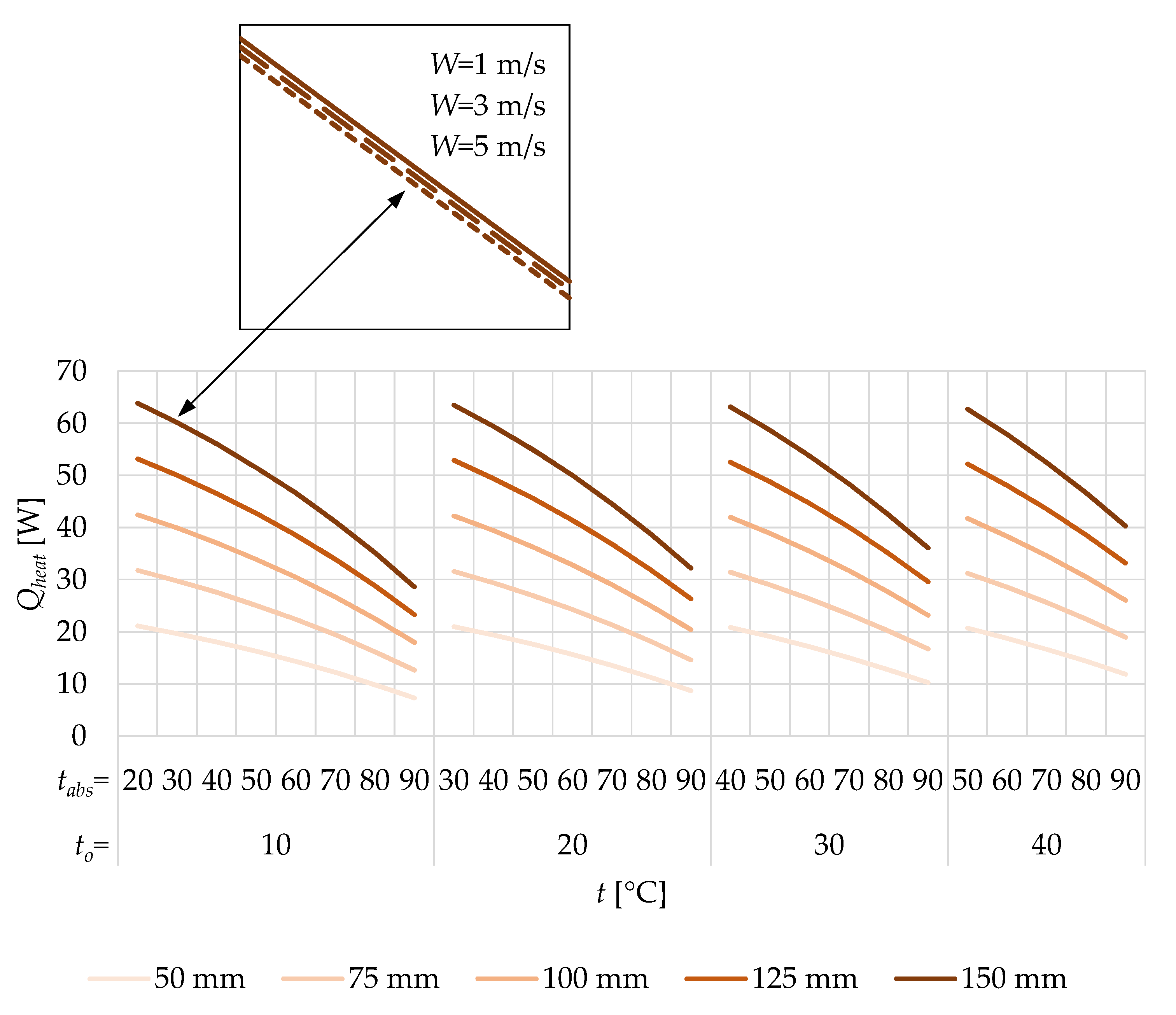
2.2.2. Useful Heat Power

When Qloss [W], derived from Equation (6), is subtracted from the absorbed (net) heat energy Qnet [W], derived from Equation (7), the Qheat [W] value is obtained, as shown in Equation (8) [28,40,45,46]:
Q l o s s = T a b s - T o R l o s s
Q n e t = A a b s , u p I t o t
Q h e a t = Q n e t Q l o s s
where Tabs [K] is the absorber temperature, To [K] is the ambient temperature, ΣRloss [K/W] is the total resistance to heat transfer (Section 2.2.3) and Itot [W/m2] is the total absorbed solar irradiance (Section 2.2.5).

2.2.3. Heat Losses

The total resistance to heat transfer in Equation (6) is equal to the sum of the total resistance to heat transfer in the transverse plane and the total resistance to heat transfer in the longitudinal plane [K/W]. They can be described as shown in Equation (9) [28,30,45,47,48]:
R l o s s = R l o s s , + R l o s s ,
where ΣRloss,⊥ [K/W] is the total resistance to heat transfer in the transverse plane and ΣRloss,∠ [K/W] is the total resistance to heat transfer in the longitudinal plane.
Since ΣRloss,∠ [K/W] is negligibly small compared to ΣRloss,⊥ [K/W] (according to recommendations in [28,30]), Equation (9) can be transformed into Equation (10):
R l o s s R l o s s ,
The structure of heat losses is now shown in Equation (11) [28,30,45]:
R l o s s R a b s g t + R g t + R g t - o
where Rabs-gt [K/W] is the resistance to heat transfer between the absorber and the glass tube, Rgt [K/W] is the resistance to heat transfer through the glass tube and Rgt-o [K/W] is the resistance to heat transfer between the glass tube and the ambient air.
The calculation of all of the values in Equation (11) is explained in detail in [30].

2.2.4. Incident Solar Irradiance

The total incident solar irradiance Gtot [W/m2], as shown in Equation (12), is the sum of the incident beam Gb [W/m2], derived from Equation (13), diffuse Gd [W/m2], derived from Equation (14), and reflected Gr [W/m2], derived from Equation (15), solar irradiance [49,50,51]:
G t o t = G b + G d + G r
G b = I b c o s θ β c o s θ z
G d = I d 1 + c o s β 2
G r = f a l b I r 1 c o s β 2
where Ib* [W/m2] is the incoming beam solar irradiance (Section 2.2.8), cosθβ [-] is the solar incident angle for a surface with an inclined N-S axis (Section 2.2.7), cosθz [-] is the solar incident angle for a horizontal surface (Section 2.2.7), Id* [W/m2] is the incoming diffuse solar irradiance (Section 2.2.8), Ir* [W/m2] is the incoming reflected solar irradiance (Section 2.2.8), β [rad] is the inclination angle (adopted β = 34°—optimal angle for Kragujevac) and falb [-] is the surface albedo (adopted falb = 0.2).

2.2.5. Absorbed Solar Irradiance

The total absorbed solar irradiance Itot [W/m2], as shown in Equation (16), is the sum of the absorbed beam Ib [W/m2], derived from Equation (17), diffuse Id [W/m2], derived from Equation (18), and reflected Ir [W/m2], derived from Equation (19), solar irradiance [28,49,50,51]:
I t o t = I b + I d + I r
I b = τ α b G b
I d = τ α d G d
I r = τ α r G r
where (next Section—Section 2.2.6) (τα)b [-] is the optical efficiency of the beam solar irradiance, (τα)d [-] is the optical efficiency of the diffuse solar irradiance and (τα)r [-] is the optical efficiency of the reflected solar irradiance.

2.2.6. Optical Efficiency

The optical efficiency depends on the nominal values of τ and α (Table 2), as well as on the solar incidence angle (Section 2.2.7). Therefore, the optical efficiencies of the beam (τα)b [-], as shown in Equation (20), diffuse (τα)d [-], as shown Equation (21), and reflected (τα)r [-], as shown Equation (22), solar irradiance are determined as follows [52,53]:
τ α b = 1.01 τ α n τ b α b α n b
τ α d = 1.01 τ α n τ d α d α n d
τ α r = 1.01 τ α n τ r α r α n r
where (τα)n [-] is the nominal optical efficiency, τb* [-] is the modifier of the beam solar irradiance for the transmittance coefficient, (αb*/αn)b is the modifier of the beam solar irradiance for the absorptance coefficient, τd* [-] is the modifier of the diffuse solar irradiance for the transmittance coefficient, (αd*/αn)d is the modifier of the diffuse solar irradiance for the absorptance coefficient, τr* [-] is the modifier of the reflected solar irradiance for the transmittance coefficient and (αr*/αn)r is the modifier of the reflected solar irradiance for the absorptance coefficient.

2.2.7. Solar Incident Angle

The solar incident angle for a surface with an inclined N-S axis cosθβ [-], as shown in Equation (23), and the solar incident angle for a horizontal surface cosθz [-], as shown in Equation (24), are as follows [28,54]:
cos θ β = cos φ cos δ cos ω cos β + sin φ sin δ cos β + sin φ cos δ cos ω sin β cos φ sin δ sin β
cos θ z = cos φ cos δ cos ω + sin φ sin δ
where φ [rad] is the latitude (adopted φ = 44.02° for Kragujevac), δ [rad] is the declination and ω [rad] is the hour angle.

2.2.8. Incoming Solar Irradiance

The total incoming solar irradiance Itot* [W/m2], as shown in Equation (25), is measured by the pyranometer. Components Ib*, derived from Equation (25), and Id, derived from Equation (26), can be calculated using the Erb’s model [55]. The last component (the reflected incoming solar radiation Ir* [W/m2]) is the sum of Ib* and Id*, as shown in Equation (27):
I b = I t o t I d
I d = K d I t o t
I r = I b + I d
where Kd [-] is the diffuse and total terrestrial solar irradiance ratio, derived from Equations (28)–(30) [55].
K d = 1 0.09 K t   if   K t 0.22
K d = 0.9511 0.1604 K t + 4.388 K t 2 16.638 K t 3 + 12.336 K t 4   if   0.22 < K t 0.8
K d = 0.165   if   K t > 0.8
where Kt [-] is the total terrestrial and total extraterrestrial solar irradiance ratio.
Finally, the value of Kt [-] is derived from Equation (31):
K t = I t o t I t o t , o
where Itot*,o [W/m2] is the incoming total extraterrestrial solar irradiance.

2.2.9. Iterative Calculation Algorithm

The iterative procedure is based on the application of the control Equations (32) and (33) in order to “balance” the applied mathematical procedure. “Balance” is necessary because the following variables are used in the calculations (Table 5): Tabs [K] (variable 3, i.e., V3), To [K] (variable 4, i.e., V4) and wind speed W [m/s] (variable 5, i.e., V5).
q a b s - g t = h a b s - g t , r a d T a b s T g t
q g t - o = T g t - o , r a d T g t - o , c o n v T g t T o
where [40,41] qabs-gt [W/m2] is the specific heat flux exchanged between the absorber and the glass tube, habs-gt,rad [W/m2K] is the radiation heat transfer coefficient between the absorber and the glass tube, qgt-o [W/m2] is the specific heat flux exchanged between the glass tube and the ambient air, hgt-o,rad [W/m2K] is the radiation heat transfer coefficient between the glass tube and the ambient air and hgt-o,conv [W/m2K] is the convection heat transfer coefficient between the glass tube and the ambient air.
The iterative procedure takes place in the following stages:
(1)
variables Tabs, To and W are adopted from Table 5;
(2)
the glass tube temperature Tgl [K] is assumed;
(3)
the results of the initial simulations are printed: Qnet, Qloss, Qheat and η;
(4)
the results of the control Equations (32) and (33) are printed;
(5)
the fulfillment of the condition |qabs-gt-qgt-o| ≤ 0.01 W/m2 (from Equations (32) and (33)) is checked.
(6)
If the condition from point 5 is met—the final simulation results are printed: Qnet, Qloss, Qheat and η;
(7)
if the condition from point 5 is not met—the value of Tgl [K] is changed and the entire process is repeated until the condition from point 5 is met.

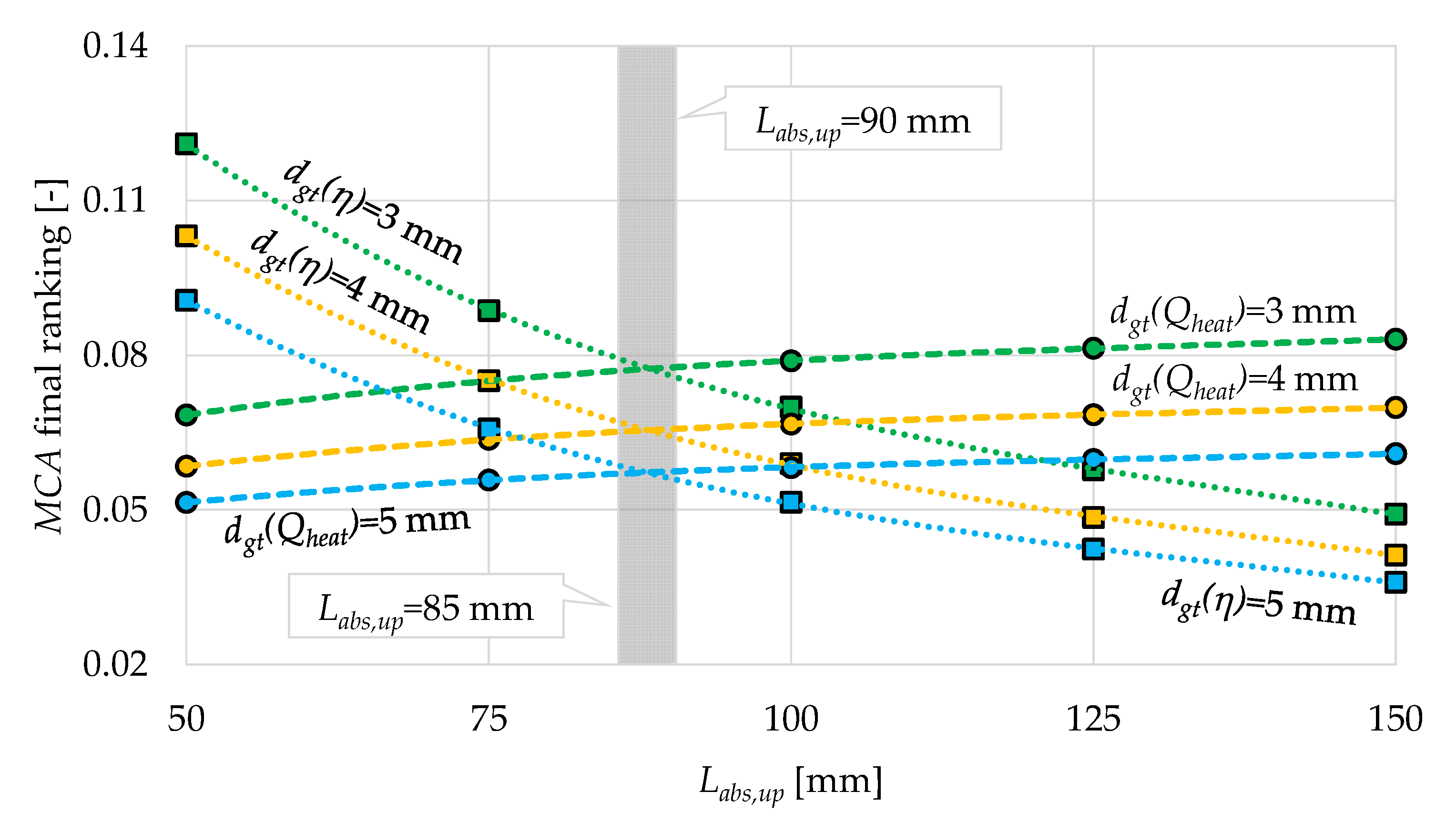
2.3. Multi-Criteria Analysis

In this study, an MCA is used to identify the optimal dimension (Labs,opt [m] and dgt,opt [m]) of the SGVTC. The analysis incorporates geometric (m, SO, TSO and VO), economic (manufacturing costs, i.e., CM [€] and operational costs, i.e., CE [€], Table 6) and ecological (embodied energy Eemb [kWh], Equation (34), and greenhouse gas emissions eCO2 [kg], Equation (35), Table 6) indicators. Economic, environmental and economic indicators are indispensable when carrying out sustainability analyses (following the global policy of sustainable development). Economic indicators are important from the point of view of the end user of the solar system. Environmental indicators are important from the point of view of environmental protection and solar system manufacturers (directly), as well as from the point of view of the end user (indirectly).
E e m b = m E e m b , s p e c 20
e C O 2 = e C O 2 , s p e c E p r y = e C O 2 , s p e c K p r y E f i n = e C O 2 , s p e c K p r y Q h e a t t i m e 1000 η e l
where Eemb,spec [kWh/kg] is the specific embodied energy (Eemb,spec = 53 kWh/kg for aluminum [56] and Eemb,spec = 25.8 kWh/kg for glass [57]), eCO2,spec [kg/kWh] is the specific CO2 emission (eCO2,spec = 0.53 kg/kWh for electricity [58]), Epry [kWh] is the primary energy consumption, Kpry [-] is the primary energy transformation coefficient (Kpry = 2.5 for electricity [58]), Efin [kWh] is the final energy consumption, time [h] is the working time and ηel [-] is the efficiency of the electric boiler (adopted ηel = 0.98).
Several MCA approaches are described in the literature. In this case, the double multi-criteria decision-making method (MCDM) using simple additive weighting (SAV) was applied [59,60,61,62]. It is a relatively simple model that provides relevant and reliable results. It is explained in detail (mathematically and graphically) in [30].
The values of the weight factors wj [-] are determined by their importance (their sum should be 1, i.e., 100%). When defining the value of wj (Table 7), The greatest priority was given to economic criteria (50%), followed by environmental criteria (36%). From the end user’s point of view, monetary costs are a priority, while overall dimensions are often less important in practice, except for some specific circumstances. Environmental protection is still not in its desired stage, but much work is being performed on it, especially in Europe.
Unlike in the previous study [30], where the MCA was applied to heat losses, in this paper, the MCA was applied to two thermal parameters (useful heat power, the first parameter, and thermal efficiency, the second parameter). This means that two independent groups of specific indicators have been created: for useful heat power (Qheat/m [W/kg], Qheat/SO [W/m2], Qheat/TSO [W/m2], Qheat/VO [W/m3], Qheat/CM [W/€], Qheat/CE [W/€], Qheat/Eemb [W/kWh] and Qheat/eCO2 [W/kg]) and for thermal efficiency (η/m [kg−1], η/SO [m−2], η/TSO [m−2], η/VO [m−3], η/CM [€−1], η/CE [€−1], η/Eemb [kWh−1] and η/eCO2 [kg−1]). For the adopted values of weight factors (Table 7) and the calculated specific indicators, the MCA aimed to perform a dimensionless ranking (final results, i.e., final marks) within both independent groups, i.e., evaluation of the results according to the used variables: V1, V2, V3, V4 and V5. The final results, i.e., the final ratings (ordinate axis), depending on the absorber widths (abstract axis), were then graphically represented by logarithmic functions (Section 4). Three (for dgt = 3 mm, dgt = 4 mm and dgt = 5 mm) logarithmic curves for useful heat power and another three for thermal efficiency were obtained. The optimal dimensions of the SGWTC (for three pairs) were located at the intersection of the logarithmic functions of useful thermal power and thermal efficiency.

3. Results and Discussion

The following diagram (Figure 2) shows the SGVTC useful heat power in the example of a 3 mm thick glass tube.
The results are show depending on the operating conditions, i.e., indicators (Table 5): absorber temperature (V3), ambient temperature (V4) and wind speed (V5).
Regardless of the operating conditions, the SGVTC useful heat power is the highest (between 28.63 and 63.866 W) when the absorber is 150 mm wide (upper limit case). As its width decreases, its useful heat power also decreases, so it is the smallest (between 7.28 and 21.09 W) when Labs = 50 mm (lower limit case). Wind speed, unlike the absorber width, negatively (but not to a greater extent) affects the performance of the analyzed SC. Therefore, the useful heat power curve for W = 1 m/s is above the useful heat power curve for W = 3 m/s, and therefore, the W = 3 m/s useful heat power curve is above the W = 5 m/s useful heat power curve (Figure 2).
The absorber temperature also reduces power. For example, if to = 30 °C, Labs = 125 mm and W = 3 m/s, Qheat, in that case, is as follows: 52.56 W (tabs = 40 °C), 48.77 W (tabs = 50 °C), 44.6 W (tabs = 60 °C), 40.03 W (tabs = 70 °C), 35.03 W (tabs = 80 °C) and 29.58 W (tabs = 90 °C). These effects can be mitigated with an increase in ambient air temperature. One more conclusion can be drawn by analyzing Figure 2—for the same temperature and width of the flat absorber plate, with an increase in the ambient temperature, the SGVTC useful heat power increases (example for Labs = 125 mm and tabs = 60 °C): 38.48 W (to = 10 °C), 41.40 W (to = 20 °C), 44.60 W (to = 30 °C), 48.09 W (to = 40 °C). These effects can be explained by the temperature driving force, which depends on the difference tabs-to. Namely, with the increase in the temperature difference tabs-to, the heat loss in the SGVTC also increases so that the useful heat power decreases. As soon as this difference decreases (between tab and to), the heat loss decreases and thermal power increases.
If the thickness of the glass tubes is increased from 3 to 4 mm, the useful heat power would be reduced between 0.47% (for Labs = 150) mm and 0.56% (for Labs = 50 mm). By increasing the thickness of the glass by another 1 mm, i.e., 5 mm, the reduction in useful heat power would be between 0.94% (for Labs = 150) mm and 1.12% (for Labs = 50 mm).
Analogous to Figure 2, Figure 3 shows the thermal efficiency of SGWTC for the same indicators.
The thermal efficiency is highest and lowest in the following two cases (for dgt = 3 mm): η = 0.68 (Labs = 150 mm, tabs = 20 °C, to = 10 °C and W = 1 m/s) and η = 0.226 (Labs = 50 mm, tabs = 90 °C, to = 10 °C and W = 5 m/s). For dgt = 4 mm (ηmax = 0.677 and ηmin = 0.224) and dgt = 5 mm (ηmax = 0.675 and ηmin = 0.221), the results are achieved for the same geometric-operational criteria as in the case of a glass thickness of 3 mm.
By comparing the different dimensions of Labs with each other, the largest gradient of change (for η value) is characteristic for Labs = 50 mm, while the smallest gradient of change (the gentlest slope of the thermal efficiency curve) is characteristic for Labs = 150 mm. On the contrary, in the case of useful heat power, the gradient of change is the largest when Labs = 150 mm (Figure 2). However, the value of η, in addition to useful heat power, also depends on Qsun (Equation (3), Section 2.2.1). The influencing term Qsun grows faster than the influencing term Qheat when the surface of the absorber increases because the solar potential of the structure also increases (Gtot, Equation (12), Section 2.2.4).
Figure 3 is practical for another reason—it can be used for the initial prediction (with satisfactory accuracy) of the thermal behavior of solar collectors of the same or similar design. This is made possible by the graphic display of characteristic tabs isotherms (dashed straight lines), designed using simple linear regression (SLR).
Following the presented methodology of using a double MCA (Section 2.3), the following diagram in Figure 4 (for dgt = 3 mm, dgt = 4 mm and dgt = 5 mm) shows the functional dependence between the MCA final ranking for useful heat power and Labs (the first group of results) and the functional dependence between the MCA final ranking for thermal efficiency and Labs (the second group).
Regardless of the thickness of the glass (while taking into account geometric, economic and ecological indicators), the MCA final ranking showed that the useful heat power is the highest when Labs = 150 mm: 0.083 (for dgt = 3 mm), 0.07 (dgt = 4 mm) and 0.061 (dgt = 5 mm). On the other hand, the MCA final ranking rated the Labs = 50 mm option as the best when it comes to thermal efficiency: 0.121 (for dgt = 3 mm), 0.103 (dgt = 4 mm) and 0.091 (dgt = 5 mm).
For this reason, both independent groups of specific indicators (Section 2.3) are represented by logarithmic functions (logarithmic curves)—with the aim of noticing that the first group has a decreasing trend and the second has a scattered trend.
It is clear that the optimal performance of the SGVTC is achieved when the useful heat power and thermal efficiency are in balance. A multidisciplinary approach showed that the balance is achieved if Labs is between 87 and 88 mm, with the preference being given to glass with a thickness of 3 mm (Figure 4). In other words, the optimal MCA final ranking for the analyzed cases is as follows: 0.078 (for dgt = 3 mm), 0.066 (dgt = 4 mm) and 0.057 (dgt = 5 mm). In a theoretical sense, it is desirable for it to be less thick, but then its mechanical characteristics and weather resistance would be called into question. Therefore, the lower limit is limited to this value.

4. Conclusions

This paper presents a novel mathematical model for the geometric optimization of a new solar collector type—a single-glazed vacuum tube collector (SGVTC) with a SnAl2O3 selective flat absorber plate and gravity-driven single-stage direct water flow. The proposed optimization approach integrates operative, geometric, economic and environmental indicators to determine two key design parameters: the flat absorber plate width and glass tube thickness.
The development of a comprehensive iterative calculation algorithm that enables the precise thermal behavior modeling of the new solar collector is undertaken. The model accounts for thermal efficiency, useful heat power, heat losses, incident solar irradiance and optical efficiency.
A novel two-step multi-criteria analysis (MCA)-based optimization strategy is proposed, which simultaneously evaluates heat power and thermal efficiency through logarithmic performance curves.
The identification of the optimal operational conditions, where useful heat power and thermal efficiency peak at an absorber width of 87–88 mm, confirm the strong correlation between geometric parameters and thermal performance.
Compared to traditional parametric studies and single-objective optimization approaches, this multi-criteria optimization method allows for a more balanced trade-off between thermal efficiency and useful heat power, rather than optimizing one parameter at the expense of another. While conventional gradient-based algorithms or evolutionary techniques (e.g., genetic algorithms) can optimize collector geometry, they often require extensive computational resources and may overlook practical constraints such as material limitations and economic feasibility. In contrast, the proposed iterative MCA approach ensures computational efficiency and integrates economic and ecological considerations, making it more applicable to real-world solar thermal systems.
Further research should explore the integration of the proposed optimization model with machine learning algorithms to enhance its predictive accuracy and allow it to adapt dynamically to changing meteorological conditions. Additionally, coupling the model with finite element analysis (FEA) and computational fluid dynamics (CFD) simulations could provide deeper insights into heat transfer mechanisms. From an application perspective, implementing the SGVTC concept in hybrid solar thermal energy systems—particularly in residential heating applications—could significantly improve energy efficiency and sustainability.
As climate change progresses, the European residential sector remains particularly vulnerable to energy supply fluctuations. Advancing renewable energy-based heating solutions, such as the proposed solar collector design, offers a dual benefit: increased energy self-sufficiency for end users and reduced environmental impact.

Author Contributions

Conceptualization, A.N. and R.K.; methodology, A.N.; software, R.K.; validation, A.N. and R.K.; formal analysis, R.K.; investigation, A.N.; resources, A.N.; data curation, R.K.; writing—original draft preparation, A.N. and R.K.; visualization, A.N. and R.K. All authors have read and agreed to the published version of the manuscript.

Funding

This research received no external funding.

Institutional Review Board Statement

Not applicable.

Informed Consent Statement

Not applicable.

Data Availability Statement

The original contributions presented in the study are included in the article, further inquiries can be directed to the corresponding author.

Conflicts of Interest

The authors declare no conflict of interest.

References

  1. National Renewable Energy Laboratory. Available online: https://www.nrel.gov/ (accessed on 3 January 2025).
  2. Alam, T.; Balam, N.B.; Kulkarni, K.S.; Siddiqui, M.I.H.; Kapoor, N.R.; Meena, C.S.; Kumar, A.; Cozzolino, R. Performance augmentation of the flat plate solar thermal collector: A review. Energies 2021, 14, 6203. [Google Scholar] [CrossRef]
  3. Olia, H.; Torabi, M.; Bahiraei, M.; Ahmadi, M.H.; Goodarzi, M.; Safaei, M.R. Application of nanofluids in thermal performance enhancement of parabolic trough solar collector: State-of-the-art. Appl. Sci. 2019, 9, 463. [Google Scholar] [CrossRef]
  4. Tyagi, V.V.; Nagilla, D.K.; Selvaraj, J.; Chopra, K.; Kothari, R.; Pandey, A.K. Thermal energy storage in phase change material integrated solar collectors for air heating application. IOP Conf. Ser. Mater. Sci. Eng. 2021, 1127, 012006. [Google Scholar] [CrossRef]
  5. Omeiza, L.A.; Abid, M.; Dhanasekaran, A.; Subramanian, Y.; Raj, V.; Kozak, K.; Mamudu, U.; Azad, A.K. Application of solar thermal collectors for energy consumption in public buildings—An updated technical review. J. Eng. Res. 2023, 12, 994–1010. [Google Scholar] [CrossRef]
  6. Evangelisti, L.; Vollaro, R.D.L.; Asdrubali, F. Latest advances on solar thermal collectors: A comprehensive review. Renew. Sustain. Energy Rev. 2019, 114, 109318. [Google Scholar] [CrossRef]
  7. Barrasso, M.; Langella, G.; Amoresano, A.; Iodice, P. Latest advances in thermal energy storage for solar plants. Processes 2023, 11, 1832. [Google Scholar] [CrossRef]
  8. Solar Water Heater. Available online: https://www.jinyi-solar.com/ (accessed on 12 January 2025).
  9. Lukić, N.; Babić, M. Solar Energy—Monography, 1st ed.; Faculty of Engineering University of Kragujevac: Kragujevac, Serbia, 2008. [Google Scholar]
  10. Sakhrieh, A.; Al-Ghandoor, A. Experimental investigation of the performance of five types of solar collectors. Energy Convers. Manag. 2013, 65, 715–720. [Google Scholar] [CrossRef]
  11. Deng, J.; O’Donovan, T.S.; Tian, Z.; King, J.; Speake, S. Thermal performance predictions and tests of a novel type of flat plate solar thermal collectors by integrating with a freeze tolerance solution. Energy Convers. Manag. 2019, 198, 111784. [Google Scholar] [CrossRef]
  12. Nikolić, N.; Lukić, N. Theoretical and experimental investigation of the thermal performance of a double exposure flat-plate solar collector. Sol. Energy 2015, 119, 100–113. [Google Scholar] [CrossRef]
  13. Abd, H.M.; Alomar, O.R.; Ali, F.A.; Salih, M.M.M. Experimental study of compound parabolic concentrator with flat plate receiver. Appl. Therm. Eng. 2020, 166, 114678. [Google Scholar]
  14. Nikolić, N.N.; Lukić, N.S.; Nešović, A.M.; Nikolić, D.M. Optimal size and position of the planar back reflector moveable only in the direction normal to the bifacial solar collector plane. Therm. Sci. 2024, 28, 4483–4497. [Google Scholar] [CrossRef]
  15. Neville, R.C. Solar energy collector orientation and tracking mode. Sol. Energy 1978, 20, 7–11. [Google Scholar] [CrossRef]
  16. Drago, P.A. A simulated comparison of the useful energy gain in a fixed and a fully tracking flat plate collector. In Proceedings of the Solar Energy International Progress, Cairo, Egypt, 16–22 June 1978. [Google Scholar]
  17. Maia, C.B.; Ferreira, A.G.; Hanriot, S.M. Evaluation of a tracking flat-plate solar collector in Brazil. Appl. Therm. Eng. 2014, 73, 953–962. [Google Scholar] [CrossRef]
  18. Nešović, A.M.; Lukić, N.S.; Josijević, M.M.; Jurišević, N.M.; Nikolić, N.N. Novel flat-plate solar collector with an inclined NS axis and relative EW tracking absorbers and the numerical analysis of its potentials. Therm. Sci. 2024, 28, 2905–2916. [Google Scholar] [CrossRef]
  19. Akhter, J.; Gilani, S.I.; Al-Kayiem, H.H.; Ali, M. Optical performance analysis of single flow through and concentric tube receiver coupled with a modified CPC collector under different configurations. Energies 2019, 12, 4147. [Google Scholar] [CrossRef]
  20. Martínez-García, A.; Vincent, M.; Rubiolo, V.; Domingos, M.; Canela, M.C.; Oller, I.; Fernández-Ibáñez, P.; Polo-López, M.I. Assessment of a pilot solar V-trough reactor for solar water disinfection. Chem. Eng. J. 2020, 399, 125719. [Google Scholar] [CrossRef]
  21. Kurhe, N.; Pathak, A.; Deshpande, K.; Jadkar, S. Compound parabolic solar collector–performance evaluation as per standard test method and actual field conditions for industrial process heat application in Indian context. Energy Sustain. Dev. 2020, 57, 98–108. [Google Scholar] [CrossRef]
  22. Chai, S.; Yao, J.; Liang, J.D.; Chiang, Y.C.; Zhao, Y.; Chen, S.L.; Dai, Y. Heat transfer analysis and thermal performance investigation on an evacuated tube solar collector with inner concentrating by reflective coating. Sol. Energy 2021, 220, 175–186. [Google Scholar] [CrossRef]
  23. Schumann, J.; Schiebler, B.; Giovannetti, F. Performance evaluation of an evacuated tube collector with a low-cost diffuse reflector. Energies 2021, 14, 8209. [Google Scholar] [CrossRef]
  24. Dinesh, S.N.; Ravi, S.; Kumar, P.M.; Subbiah, R.; Karthick, A.; Saravanakumar, P.T.; Pranav, R.A. Study on an ETC solar water heater using flat and wavy diffuse reflectors. Mater. Today Proc. 2021, 47, 5228–5232. [Google Scholar] [CrossRef]
  25. Li, Q.; Zheng, C.; Shirazi, A.; Mousa, O.B.; Moscia, F.; Scott, J.A.; Taylor, R.A. Design and analysis of a medium-temperature, concentrated solar thermal collector for air-conditioning applications. Appl. Energy 2017, 190, 1159–1173. [Google Scholar] [CrossRef]
  26. Li, Q.; Zheng, C.; Mesgari, S.; Hewkuruppu, Y.L.; Hjerrild, N.; Crisostomo, F.; Rosengarten, G.; Scott, J.A.; Taylor, R.A. Experimental and numerical investigation of volumetric versus surface solar absorbers for a concentrated solar thermal collector. Sol. Energy 2016, 136, 349–364. [Google Scholar] [CrossRef]
  27. Li, Q.; Tehrani, S.S.M.; Taylor, R.A. Techno-economic analysis of a concentrating solar collector with built-in shell and tube latent heat thermal energy storage. Energy 2017, 121, 220–237. [Google Scholar] [CrossRef]
  28. Nešović, A.; Lukić, N.; Taranović, D.; Nikolić, N. Theoretical and experimental investigation of the glass tube solar collector with inclined NS axis and relative EW single-axis tracking flat absorber. Appl. Therm. Eng. 2024, 236, 121842. [Google Scholar] [CrossRef]
  29. Bellos, E.; Tzivanidis, C. A detailed investigation of an evacuated flat plate solar collector. Appl. Therm. Eng. 2023, 234, 121334. [Google Scholar] [CrossRef]
  30. Nešović, A.; Kowalik, R.; Cvetković, D.; Janaszek, A. Multi-criteria decision-making method for simple and fast dimensioning and selection of glass tube collector type based on the iterative thermal resistance calculation algorithm with experimental validation. Appl. Sci. 2024, 14, 6603. [Google Scholar] [CrossRef]
  31. Ditta, A.; Tabish, A.N.; Mujtaba, M.A.; Amjad, M.; Yusuf, A.A.; Chaudhary, G.Q.; Razzaq, L.; Abdelrahman, A.; Kalam, M.A. Experimental investigation of a hybrid configuration of solar thermal collectors and desiccant indirect evaporative cooling system. Front. Energy Res. 2022, 10, 979942. [Google Scholar] [CrossRef]
  32. Supankanok, R.; Sriwong, S.; Ponpo, P.; Wu, W.; Chandra-Ambhorn, W.; Anantpinijwatna, A. Modification of a solar thermal collector to promote heat transfer inside an evacuated tube solar thermal absorber. Appl. Sci. 2021, 11, 4100. [Google Scholar] [CrossRef]
  33. Ma, L.; Lu, Z.; Zhang, J.; Liang, R. Thermal performance analysis of the glass evacuated tube solar collector with U-Tube. Build. Environ. 2010, 45, 1959–1967. [Google Scholar] [CrossRef]
  34. Kaya, H.; Arslan, K. Numerical investigation of efficiency and economic analysis of an evacuated U-tube solar collector with different nanofluids. Heat Mass Transf. 2019, 55, 581–593. [Google Scholar] [CrossRef]
  35. Morrison, G.L.; Budihardjo, I.; Behnia, M. Measurement and simulation of flow rate in a water-in-glass evacuated tube solar water heater. Sol. Energy 2005, 78, 257–267. [Google Scholar] [CrossRef]
  36. Budihardjo, I.; Morrison, G.L.; Behnia, M. Natural circulation flow through water-in-glass evacuated tube solar collectors. Sol. Energy 2007, 81, 1460–1472. [Google Scholar] [CrossRef]
  37. Glembin, J.; Rockendorf, G.; Scheuren, J. Internal thermal coupling in direct-flow coaxial vacuum tube collectors. Sol. Energy 2010, 84, 1137–1146. [Google Scholar] [CrossRef]
  38. Abokersh, M.H.; El-Morsi, M.; Sharaf, O.; Abdelrahman, W. An experimental evaluation of direct flow evacuated tube solar collector integrated with phase change material. Energy 2017, 139, 1111–1125. [Google Scholar] [CrossRef]
  39. Rezaeian, M.; Dehaj, M.S.; Mohiabadi, M.Z.; Salarmofrad, M.; Shamsi, S. Experimental investigation into a parabolic solar collector with direct flow evacuated tube. Appl. Therm. Eng. 2021, 189, 116608. [Google Scholar] [CrossRef]
  40. Rabl, A. Active Solar Collectors and Their Applications, 1st ed.; Oxford University Press: New York, NY, USA, 1985. [Google Scholar]
  41. Yang, X.; Heng, K.; Dai, X.; Wu, X.; Liu, G. A Temperature-Dependent Cauer Model Simulation of IGBT Module With Analytical Thermal Impedance Characterization. IEEE J. Emerg. Sel. Top. Power Electron. 2022, 10, 3055–3065. [Google Scholar] [CrossRef]
  42. Zhang, J.; Shen, H.; Du, X.; Chen, R. Condition Monitoring the Inhomogeneous Thermal Fatigue of Multichip IGBT Module Based on the Thermal Attenuation Coefficient. IEEE Trans. Power Electron. 2025, 40, 2114–2125. [Google Scholar] [CrossRef]
  43. Orman, Ł.J. Enhancement of pool boiling heat transfer with pin-fin microstructures. J. Enhanc. Heat Transf. 2016, 23, 137–153. [Google Scholar] [CrossRef]
  44. Kowalik, R.; Nešović, A.; Cvetković, D.; Janaszek, A.; Kozłowski, T. Numerical Simulation of Climate Change Impact on Energy, Environmental and Economic Performances of Small Single-Family Houses Equipped with Trombe Walls and Fixed Horizontal Overhangs. Energies 2024, 17, 6275. [Google Scholar] [CrossRef]
  45. Rajput, R.K. Engineering Thermodynamics, 3rd ed.; Jones & Bartlett Publishers: Boston, MA, USA, 2007. [Google Scholar]
  46. Kalogirou, S.A.; Karellas, S.; Braimakis, K.; Stanciu, C.; Badescu, V. Exergy analysis of solar thermal collectors and processes. Prog. Energy Combust. Sci. 2016, 56, 106–137. [Google Scholar] [CrossRef]
  47. Dąbek, L.; Kapjor, A.; Orman, Ł.J. Ethyl alcohol boiling heat transfer on multilayer meshed surfaces. AIP Conf. Proc. 2016, 1745, 020005. [Google Scholar]
  48. Majewski, G.; Telejko, M.; Orman, Ł.J. Preliminary results of thermal comfort analysis in selected buildings. E3S Web Conf. 2017, 17, 00056. [Google Scholar] [CrossRef]
  49. Tang, R.; Gao, W.; Yu, Z.; Chen, H. Optimal tilt-angles of all-glass evacuated tube solar collectors. Energy 2009, 34, 1387–1395. [Google Scholar] [CrossRef]
  50. Mehregan, M.; Abbasi, M.; Khalilian, P.; Majid Hashemian, S.; Madadi, A. Energy, economic, environmental investigations and optimization of a combined cooling, heating and power system with hybrid prime mover of gas engine and flat plate solar collector. Energy Convers. Manag. 2022, 251, 115018. [Google Scholar] [CrossRef]
  51. Shah, L.J.; Furbo, S. Vertical evacuated tubular-collectors utilizing solar radiation from all directions. Appl. Energy 2004, 78, 371–395. [Google Scholar]
  52. Hellstrom, B.; Adsten, M.; Nostell, P.; Karlsson, B.; Wackelgard, E. The impact of optical and thermal properties on the performance of flat plate solar collectors. Renew. Energy 2003, 28, 331–344. [Google Scholar] [CrossRef]
  53. Porowski, R.; Kowalik, R.; Grzmiączka, M.; Jurišević, N.; Gawdzik, J. Influence of initial temperature on laminar burning velocity in hydrogen-air mixtures as potential for green energy carrier. Int. Commun. Heat Mass Transf. 2023, 146, 106861. [Google Scholar] [CrossRef]
  54. Nešović, A. Theoretical model of solar incident angle for an optionally oriented fixed flat surface. Technique 2022, 72, 328–333. [Google Scholar] [CrossRef]
  55. Erbs, D.G.; Klein, S.A.; Duffie, J.A. Estimation of the diffuse radiation fraction for hourly, daily and monthly-average global radiation. Sol. Energy 1982, 28, 293–302. [Google Scholar] [CrossRef]
  56. Recycling Today. Available online: https://www.recyclingtoday.com (accessed on 10 January 2025).
  57. Ramesh, T.; Prakash, R.; Shukla, K.K. Life cycle approach in evaluating energy performance of residential buildings in Indian context. Energy Build. 2012, 54, 259–265. [Google Scholar] [CrossRef]
  58. Ministry of Construction Transport and Infrastructure. Rulebook of Energy Efficiency. Available online: https://www.mgsi.gov.rs (accessed on 9 January 2025).
  59. Mitra, S.; Goswami, S.S. Application of simple average weighting optimization method in the selection of best desktop computer model. Adv. J. Grad. Res. 2019, 6, 60–68. [Google Scholar] [CrossRef]
  60. Kumar, A.; Sah, B.; Singh, A.R.; Deng, Y.; He, X.; Kumar, P.; Bansal, R.C. A review of multi-criteria decision making (MCDM) towards sustainable renewable energy development. Renew. Sustain. Energy Rev. 2017, 69, 596–609. [Google Scholar] [CrossRef]
  61. Puška, A.; Beganović, A.I.; Šadić, S. Model for investment decision making by applying the multi-criteria analysis method. Serbian J. Manag. 2018, 13, 7–28. [Google Scholar] [CrossRef]
  62. Nešović, A.; Kowalik, R.; Bojović, M.; Janaszek, A.; Adamczak, S. Elevational Earth-Sheltered Buildings with Horizontal Overhang Photovoltaic-Integrated Panels—New Energy-Plus Building Concept in the Territory of Serbia. Energies 2024, 17, 2100. [Google Scholar] [CrossRef]
Figure 1. Design of the SGVTC: (a) isometric view and (b) cross-sectional view. List of symbols: dgt [m] is the glass tube thickness (variable 2, i.e., V2) and Labs,up [m] is the upper side width of the absorber (variable 1, i.e., V1).
Applsci 15 01838 g001
Figure 2. Useful heat power of the SGVTC for different values of absorber temperature, ambient temperature and wind speed (the thickness of the GT is 3 mm).
Applsci 15 01838 g002
Figure 3. Thermal efficiency of the SGVTC for different values of absorber temperature, ambient temperature and wind speed (the thickness of the GT is 3 mm).
Applsci 15 01838 g003
Figure 4. Geometric optimization of the SGVTC using the double MCA.
Applsci 15 01838 g004
Table 1. Some literature examples of the modified FPC and ETC constructions.
SC TypeModificationMethodDescriptionMain ResultsYearSource
FPCReflectorMath/ExpManually operated mirror in all
three orthogonal directions
η higher by 29.55%2015[12]
ExpCPC/Externalη higher by 26.5%2020[13]
MathMoveable in the direction
normal to the bifacial SC plane
η higher by 54–74%2024[14]
Tracking
mechanism
MathSAT/Inclined axis/E-W direction
DAT
Gtot = 1370 kW/hr/m2
Gtot = 1460 kW/hr/m2
1978[15]
DATη higher by 20%[16]
SAT/Horizontal axis/N-S direction
SAT/Horizontal axis/E-W direction
SAT/Vertical axis/E-W direction
SAT/Inclined axis/E-W direction
DAT
η = 57.12%
η = 62.17%
η = 59.51%
η = 64.36%
η = 67.25%
2014[17]
NumrSAT/Inclined axis/E-W directionη higher by 20%2024[18]
ETCReflectorNumCPC/External/N-S installation
CPC/External/E-W installation
η = 69%
η = 66.5%
2019[19]
ExpV-troughWater treatment
higher by 66%
2020[20]
CPC/Externalη = 45–64%2020[21]
Math/ExpCPC/Internalη = 65–72%2021[22]
Math/Num/ExpLow-cost/TrapezoidalQheat higher by 30%2021[23]
ExpFlat
Wavy
ttw higher by 4 °C
ttw higher by 6 °C
[24]
Tracking
mechanism
Math/Num/ExpCPC/Internal/rSAT/
Inclined axis/E-W direction
η = 54% at 80 °C
η = 26% at 200 °C
2016/2017[25,26,27]
FPC/ETCTracking
mechanism
Math/ExpABS/GT/rSAT/Inclined axis/
E-W direction
Qheat higher by 14–23%2024[28]
Specific
solutions
Math/NumDifferent
temperature
operation
η = 47.24%2023[29]
Math/ExpABS/SGT/AL
ABS/SGT/VL
ABS/DGT/AL
ABS/DGT/VL
Qloss = 5.29–64.42 W
Qloss = 2.74–27.11 W
Qloss = 12.65–47.14 W
Qloss = 6.48–23.35 W
2024[30]
List of abbreviations: ABS is the absorber, AL is the air layer, CPC is the compound parabolic collector, DAT is the dual-axis tracking mechanism, DGT is the double-glazed tube, GT is the glass tube, rSAT is the relative single-axis tracking mechanism, SAT is the single-axis tracking mechanism, SGT is the single-glazed tube and VL is the vacuum layer. List of symbols: Gtot [W/m2] is the total incident solar irradiance (Section 2.2.4), Qheat [W] is the useful heat power (Section 2.2.2), Qloss [W] is the heat loss (Section 2.2.3) and ttw [°C] is the tank water temperature. List of Greek letters: η [-] is the thermal efficiency (Section 2.2.1).
Table 2. Thermal and optical performances of the main SGVTC components.
ComponentMaterialρ [kg/m3]k [W/(mK)]τ [-]α [-]ε [-]
FAPAluminum2700203-0.880.25
GTGlass22000.80.9-0.9
List of symbols: k [W/(mK)] is the thermal conductivity. List of Greek letters: α [-] is the nominal absorptance, ε [-] is the nominal emissivity, ρ [kg/m3] is the density and τ [-] is the nominal transmittance.
Table 3. Geometric performances of the FAP in SGVTC construction, depending on the simulation scenario.
Scenariom [kg]SO [m2]TSO [m2]VO [m3]
Labs,up = 50 mm0.4680.40.1040.000315
Labs,up = 75 mm0.5750.60.1440.000355
Labs,up = 100 mm0.6830.80.1840.000395
Labs,up = 125 mm0.7910.10.2240.000435
Labs,up = 150 mm0.8980.120.2640.000475
List of symbols: m [kg] is the mass, SO [m2] is the surface occupation, TSO [m2] is the total surface occupation and VO [m3] is the volume occupation.
Table 4. Geometric performances of the GT in SGVTC construction, depending on the simulation scenario.
Scenariom [kg]SO [m2]TSO [m2]VO [m3]
Labs,up = 50 mmdgt = 3 mm0.9460.0480.1510.00226
dgt = 4 mm1.2830.04960.1560.00241
dgt = 5 mm1.6320.05120.1610.00257
Labs,up = 75 mmdgt = 3 mm1.3610.0680.2140.00454
dgt = 4 mm1.8360.06960.2190.00475
dgt = 5 mm2.3230.07120.2240.00497
Labs,up = 100 mmdgt = 3 mm1.7750.0880.2760.0076
dgt = 4 mm2.3890.08960.2810.00788
dgt = 5 mm3.0140.09120.2860.00816
Labs,up = 125 mmdgt = 3 mm2.190.1080.3390.01145
dgt = 4 mm2.9420.10960.3440.01179
dgt = 5 mm3.7060.11120.3490.01213
Labs,up = 150 mmdgt = 3 mm2.6050.1280.4020.01608
dgt = 4 mm3.4950.12960.4070.01648
dgt = 5 mm4.3970.13120.4120.01689
Table 5. Adopted variable values in the iterative calculation algorithm.
VariableUsed Values
V3tabs [°C]20; 30; 40; 50; 60; 70; 80; 90
V4to [°C]10; 20; 30; 40
V5W [m/s]1; 3; 5
Table 6. Economic and ecological indicators (GT and FAP) of SGVTC construction depending on the simulation scenario.
ScenarioCM [€]CE [€]Eemb [kWh]eCO2 [kg]
Labs,up = 50 mmdgt = 3 mm57.60528.8032.461048.943
dgt = 4 mm72.04736.0242.8951043.093
dgt = 5 mm86.96343.4823.3441037.29
Labs,up = 75 mmdgt = 3 mm79.30339.6513.281625.579
dgt = 4 mm99.66449.8323.8941617.312
dgt = 5 mm120.49960.2494.5221609.072
Labs,up = 100 mmdgt = 3 mm10150.54.12202.293
dgt = 4 mm127.2863.644.8922191.592
dgt = 5 mm154.03477.0175.6992180.907
Labs,up = 125 mmdgt = 3 mm122.69761.3494.9212779.042
dgt = 4 mm154.89777.4485.8912765.9
dgt = 5 mm187.5793.7856.8762752.768
Labs,up = 150 mmdgt = 3 mm144.39572.1975.7413355.801
dgt = 4 mm182.51391.2576.893340.215
dgt = 5 mm221.105110.5538.0533324.632
Table 7. Weight of importance of each criterion for the SAW analysis.
CriterionGeometricEconomicEcologicalSum
wj [%]145036100
Sub-criterionmSOTSOVOCMCEEembeCO2SGVTC
wj,sc [%]552235151818100
Disclaimer/Publisher’s Note: The statements, opinions and data contained in all publications are solely those of the individual author(s) and contributor(s) and not of MDPI and/or the editor(s). MDPI and/or the editor(s) disclaim responsibility for any injury to people or property resulting from any ideas, methods, instructions or products referred to in the content.

