Article

Fatigue Resistance Improvement in Cold-Drawn NiTi Wires Treated with ALD: A Preliminary Investigation

by
David Vokoun
1,*,
Ondřej Tyc
1,
Sneha Manjaree Samal
1,
Ivo Stachiv
1,†,
Yoshane Yu
2 and
Chichung Kei
2,*
1
Institute of Physics of the Czech Academy of Sciences, Na Slovance 1999/2, 182 00 Prague, Czech Republic
2
Taiwan Instrument Research Institute, National Applied Research Laboratories, 20 R&D Road VI, Hsinchu Science Park, Hsinchu 300, Taiwan
*
Authors to whom correspondence should be addressed.
I. Stachiv is currently Seconded at the European Research Council (ERC) Executive Agency of the European Commission. The views expressed in this article are purely those of the authors. They do not necessarily reflect the views or official positions of the European Commission and the ERC Executive Agency.
Appl. Sci. 2025, 15(4), 1823; https://doi.org/10.3390/app15041823
Submission received: 9 December 2024 / Revised: 3 February 2025 / Accepted: 5 February 2025 / Published: 11 February 2025

Abstract

:
NiTi shape memory alloys (SMAs) are widely studied for their potential applications, and atomic layer deposition (ALD) is an effective technique for coating them due to its precise control over coating thickness. This study investigates the impact of Al2O3 coating on the fatigue behavior of cold-drawn NiTi wires with a 0.125 mm diameter. The wires were coated using atomic layer deposition (ALD) with 100 ALD cycles. Fatigue tests were conducted in tensile mode at room temperature, applying cyclic loading between 0–50, and 700 MPa (700 MPa is almost 40% of ultimate tensile strength). The results show that the cold-drawn NiTi wires failed after an average of 7500 tensile loading cycles, while the lifetime of the coated and stretched NiTi wires with a preload of 1.7–2.8 kg significantly improved, with an average of 293,000 cycles before failure.

1. Introduction

1.1. NiTi Shape Memory Alloys and Their Applications

It has been more than 60 years since the discovery of an approximately equiatomic NiTi alloy called Nitinol. The last three letters in the alloy’s name stand for Naval Ordnance Laboratory, the place of the discovery [1]. During these six decades, NiTi shape memory alloys (SMAs), well known for the shape memory effect and superelasticity due to the reversible solid phase martensitic transformation [2,3,4], have found many applications in industry and medicine. These unique properties allow NiTi alloys to recover their original shape after deformation and to exhibit high elasticity, making them invaluable in various engineering and biomedical applications.
Some examples of NiTi applications include NiTi frames of reading glasses [5], an NiTi switch-off element in electric tea kettles [6], and NiTi pipe couplers used, among other things, to connect titanium hydraulic tubing in the Grumman F-14 aircraft [7]. Additionally, NiTi is used in various actuators and sensors [8,9], fasteners such as Velcro-type NiTi hook fasteners [10], vibration and seismic applications [11], NiTi torque tubes installed in smart wings for wing morphing [12], NiTi self-expandable stents [13], and NiTi elements used in endoscopes [14]. The versatility of NiTi SMAs arises from their ability to perform reliably under cyclic loading conditions, which is critical for dynamic applications.
However, some of the mentioned applications, and not only those, are limited by the fatigue life of cyclically loaded NiTi elements (e.g., Velcro-type NiTi hook fasteners or elastocaloric active regenerators [15]). The degradation of mechanical properties due to repeated stress cycles can lead to premature failure, posing safety risks and reducing the operational lifespan of components. Hence, fatigue-life studies of cyclically loaded NiTi parts have received much attention [16,17]. Understanding the mechanisms of fatigue failure and identifying methods to enhance fatigue resistance are essential for extending the durability and reliability of NiTi-based components. Not long ago, some techniques, such as laser shock peening and shot peening [18,19,20], were proposed to improve the fatigue strength of alloy parts, which are also applicable to NiTi wires by generating compressive stresses on the surface.

1.2. Cold-Drawn NiTi Wires

The application potential of cold-drawn NiTi wires is lower than that of superelastic and shape-memory NiTi wires. Thin (<1 mm diameter) cold-drawn NiTi wires, typically consisting of a mixture of austenite (B2), martensite (B19′), and amorphous phase, have high tensile strength at room temperature, of the order of 1.5 GPa (depending on the amount of cold work) and maximum elongation of 3–4% [21]. These mechanical properties make cold-drawn NiTi wires suitable for applications requiring high strength and moderate flexibility, though their limited superelastic behavior restricts broader use.
To our knowledge, there are only a few studies on the fatigue strength of cold-drawn NiTi wires. Hua et al. presented high fatigue resistance of NiTi micro-pillars composed of alternating amorphous and nanocrystalline layers under compressive loading [22]. Schaffer and Plumley, using a rotary bend fatigue tester, studied the fatigue life of superelastic wires, thus not directly the fatigue life of as-drawn wires; however, they paid attention to the amount of prior cold work [23]. This gap in research highlights the need for comprehensive studies on the fatigue performance of cold-drawn NiTi wires, especially under tensile and cyclic loading conditions relevant to practical applications. Cold drawn NiTi wires, characterized by their high tensile strength, find direct applications in environments where mechanical robustness and corrosion resistance are critical.

1.3. Atomic Layer Deposition

Atomic layer deposition (ALD) is an attractive CVD (Chemical Vapor Deposition) method [24] that is well applicable to NiTi SMAs [25,26,27,28,29] due to the well-controllable coating thickness and outstanding conformality of the ALD coatings. No other thin-film technique can approach the conformality achieved by ALD on high-aspect-ratio structures, such as trench capacitors for DRAM (Dynamic Random-Access Memory) [30] or microcracks in an alloy. The ALD coating has the potential to improve the biocompatibility and corrosion resistance of NiTi [31], which is particularly important for medical implants and devices exposed to harsh physiological environments.
The idea of using ALD coating on the NiTi surface was first realized 10 years ago [25]. However, the drawback of the ALD coatings applied to NiTi might be delamination due to large surface strains in NiTi (up to 10%, locally) [26], especially if the coating is made of ceramic material. Despite these challenges, ALD remains a promising technique for enhancing the surface properties of NiTi components. In the present study, the ALD method is used, for the first time, on a stretched NiTi thin wire to improve fatigue resistance. This innovative approach aims to explore the potential of ALD coatings to mitigate fatigue-related failures by providing a protective barrier that can withstand cyclic mechanical stresses.

2. Experimental

2.1. NiTi Wire Samples

A NiTi as-drawn wire with a diameter of 0.125 mm was purchased from Smatec (Belgium). The length of the prepared wire samples ranged from 60 to 70 mm. Steel capillaries 20–30 mm long, with an inner diameter of 0.180 mm, were attached to both ends of the wire samples to facilitate the stretching of these samples. Special care was taken in attaching the capillaries. The attachment was achieved by inserting the NiTi wire and compressing the capillaries together with the wire. However, the applied compressive force was carefully controlled to prevent damage to the wire at the critical point where it exits the capillary. If breakage occurred at this critical point during fatigue testing, the corresponding test results were excluded from the analysis.
The ultimate elongation and ultimate tensile strength of the as-drawn NiTi wires were 4–5% and 1700–1850 MPa, respectively. After annealing at 400–450 °C for 5 min, the wires exhibited superelasticity at room temperature.
Wire samples intended for the ALD were cleaned according to the following procedure:
(i)
Cleaning in IPA (isopropyl alcohol) by sonication for 5 min,
(ii)
cleaning in DI (deionized) water by sonication for 5 min,
(iii)
cleaning in Ethyl alcohol by sonication for 5 min,
(iv)
cleaning in DI water by sonication for 5 min.
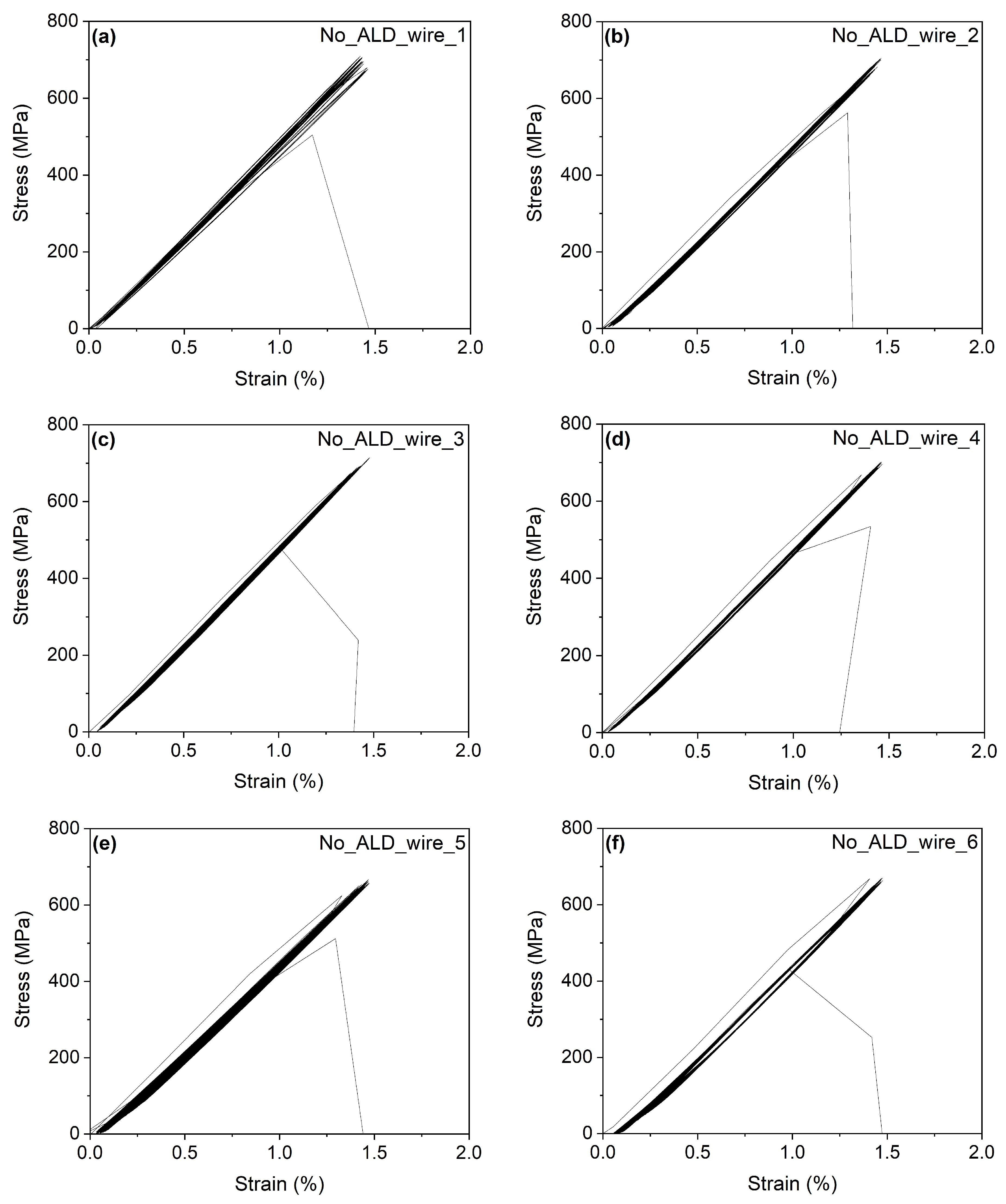
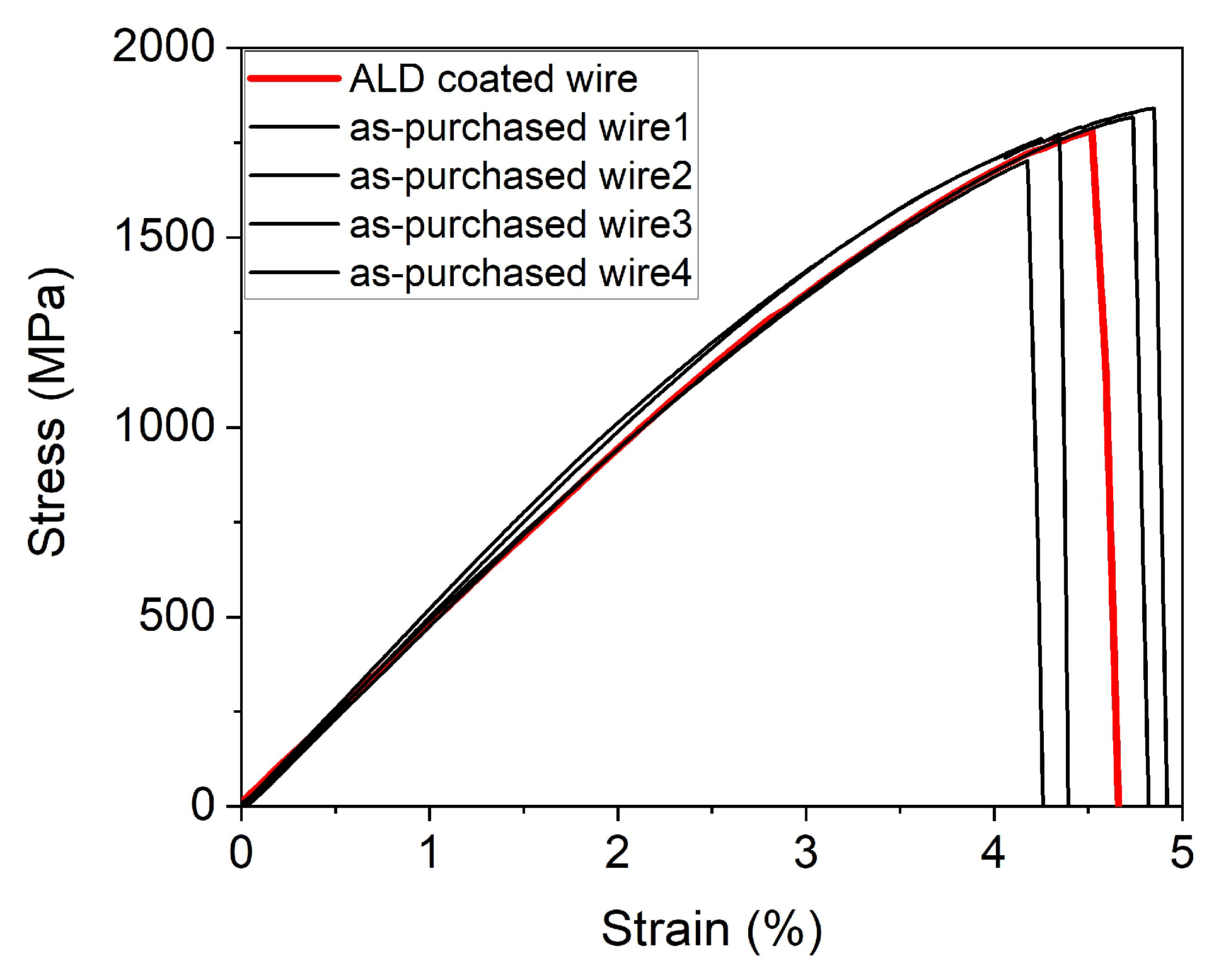
The procedure was repeated twice, and finally, the samples were dried out in nitrogen gas flow.

2.2. Fatigue Tests

The fatigue tension tests were carried out using a custom-made tensile tester MITTER (Miniature Tensile Tester) equipped with an environmental chamber, electrically conductive grips, a load cell, a linear stepping motor, and a position sensor. The testing device enabled us to control temperature and stress and measure strain and electric resistance of the wire samples. More details of MITTER can be found in Ref. [32]. The fatigue tests were conducted at room temperature, with cyclic loading in the stress range of 0 to 700 MPa, where the minimum stress varied between 0 and 50 MPa, until the wire specimen fractured.

2.3. The ALD Process

The ALD was realized with a custom-made deposition system at TIRI (Hsinchu, Taiwan). In the ALD process, trimethylaluminum (TMA) was used as a precursor of Al, whereas water vapor served as an oxygen source. One typical ALD cycle consisted of 0.2 s TMA precursor pulse followed by 10 s N2 purge (2 Torr) to remove excess precursor and the by-products. After the N2 purge, a 0.1 s water pulse was applied followed by another 10 s N2 purge to complete the ALD cycle. The pumping time after each purge was 2 s. Each deposition consisted of just 100 ALD cycles (100 Al2O3 ALD cycles on NiTi surface corresponds to Al2O3 thickness of about 10 nm [25]). The temperature of NiTi wire samples in the ALD chamber was influenced by preheated gasses and gas tubes; hence, temperature might fluctuate during the deposition; however, it did not exceed 100 °C. The wire samples were stretched in the ALD chamber and held in a stretched state during the deposition, with different loads of 1.7, 2.2, and 2.8 kg applied, which remained constant within a single deposition (Figure 1). The tensile force acting on the wire was influenced by the applied load (1.7, 2.2, and 2.8 kg) and the chamber pressure (2 Torr, during N2 purging). A decrease in chamber pressure resulted in a corresponding decrease in tensile force.

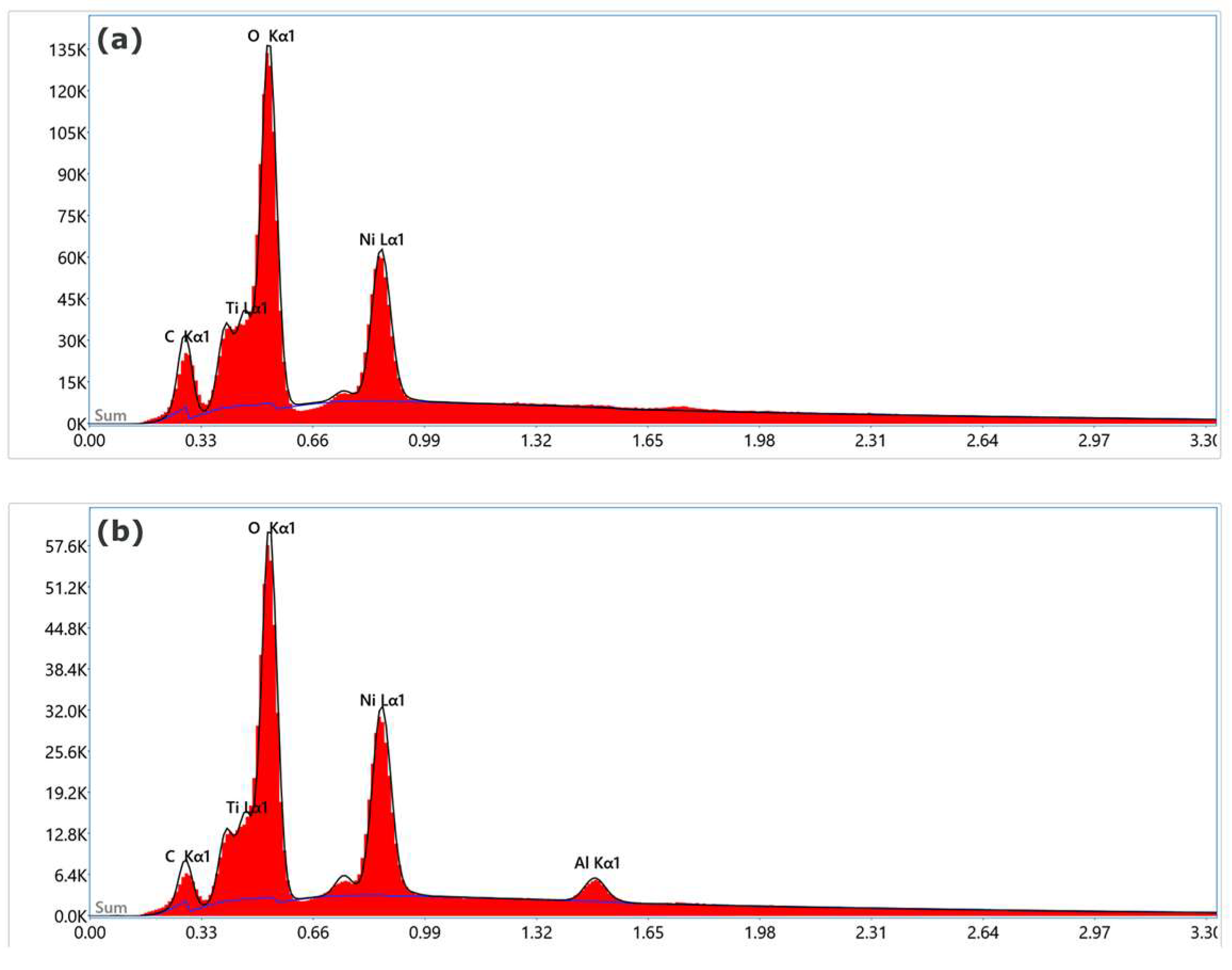
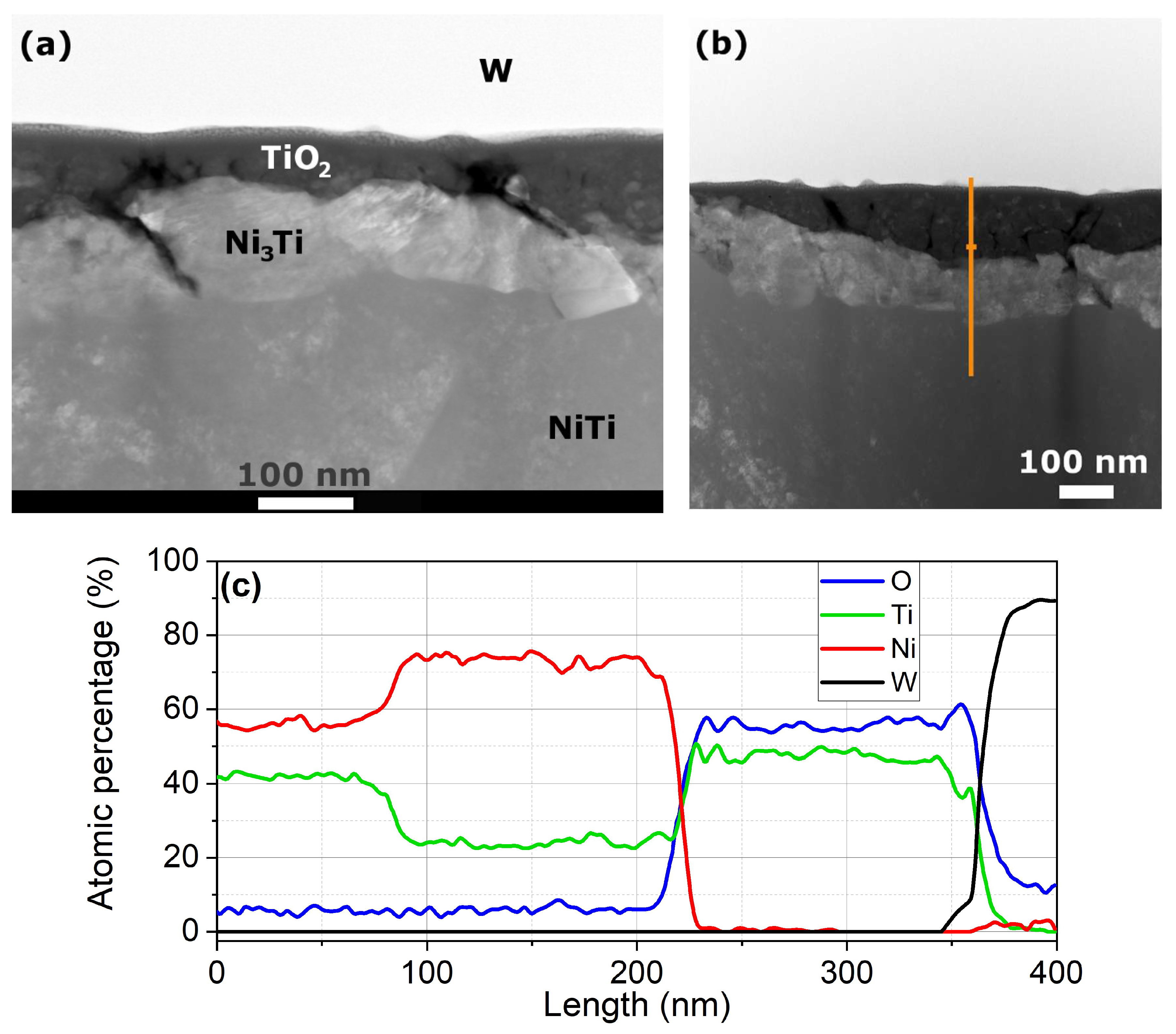
2.4. Analysis of NiTi Wire Samples Using Electron Microscopy

The surfaces of the as-purchased NiTi wire and NiTi wire with ALD coating were examined using scanning electron microscope (SEM) (Tescan, FERA 3 (TESCAN Brno, s.r.o., Brno, Czechia)). Samples for transmission electron microscopy (TEM) of the mechanically cycled wires (until the fracture) were prepared using the Focused Ion Beam (FIB) method using FEI Quanta 3D FIB-SEM electron microscope (FEI Quanta: Thermo Fisher Scientific, Waltham, WA, USA). The FIB system, equipped with a local ion source (LIS), employed gallium ions for precise material removal. Prior to FIB machining, a tungsten layer was locally deposited on the wire surface within the chamber to protect it during the FIB process. TEM lamellas were extracted from the mechanically cycled wire sample to see cross-sectional area adjacent to the wire surface. The following accelerating voltages and FIB currents were applied: 30 kV and 15–30 nA for coarse milling, 30 kV and 0.5–3 nA for moderate milling, and 5 kV and 48 pA for fine milling. The HAADF (high-angle annular dark field) images were obtained to identify the individual layers adjacent to the surface using TEM (FEI Tecnai TF20 X-twin field emission gun (FEI Tecnai: Thermo Fisher Scientific, WA, USA)).

3. Results and Discussion

The idea of potentially increased fatigue life of a wire consists of depositing of ALD coating on the surface of the stretched wire (Figure 2). During stretching, it is assumed that many microcracks on the surface become open. (Multiple mechanical load cycles can be applied in advance to increase the microcrack density on the surface). ALD is a promising method that enables uniform coated layer thickness even in microcracks. After the deposition and unloading, it is assumed that compressive stress (σ < 0) forms in the vicinity of each microcrack, which has a positive effect for suppressing further growth of the microcracks. Al2O3 coating was chosen because of the possibility of depositing Al2O3 layers at a relatively low temperature of the sample [33], the biocompatibility of Al2O3 [34], wear resistance, and high Young’s modulus [35,36,37]. However, in our study, it was not possible to reduce the deposition temperature to room temperature. Hence, the potential influence of unintended heat treatment on fatigue resistance cannot be excluded in this study. To assess the effect of this unintended heat treatment during the ALD process, loading-to-rupture experiments were conducted. Given that the deposition temperature exceeds room temperature, we chose to work with as-drawn NiTi wires rather than annealed wires, as the thermomechanical properties of the latter are more sensitive to temperature variations.
The wire surfaces of the as-purchased and Al2O3-coated NiTi wires are shown in Figure 3. Due to the nanometric thickness of the coating, there is no clear indication of an Al2O3 layer from Figure 3. Even Figure 3d, which is the back-scatter electron image showing a more compositional than surface relief contrast, provides no evidence of an Al2O3 layer composed of the light elements. However, Figure 3 presents a basic characterization of the wire surface. Cracks and signs of delamination in the naturally formed TiO2 layer are visible. The white arrows in the SEM images indicate microcracks in the exposed alloy region where the TiO2 layer has detached. The large plastic deformations induced during the cold-drawing process conducted by the wire producer are well accommodated by the NiTi matrix; however, they are detrimental to the brittle, naturally grown TiO2 ceramic layer.
The presence (or absence) of Al2O3 on the surface of the ALD-coated (or uncoated) sample can primarily be determined from the EDS (energy-dispersive X-ray spectroscopy) analysis. The Al K peak is clearly visible in the energy-dispersive X-ray spectrum of the coated-wire sample with the applied Al2O3 (Figure 4b), whereas no aluminum peak is present in the spectrum of the as-purchased NiTi wire (Figure 4a).
Table 1 presents the number of mechanical loading cycles (fatigue or tensile cycles) to fracture (Nf) for the as-purchased samples. The average number of cycles, Nf_mean, is 7535 cycles, with a relatively large standard deviation (SD = 6219 cycles). This variability could potentially be explained by differences in the degree of crystallinity of the samples, as well as the random formation of critical microcracks that may arise during the wire drawing process. These factors are proposed as possible contributors, though further investigation would be required to confirm their impact.
The number of mechanical cycles until the fracture of the coated wires is summarized in Table 2. The average value, Nf_ald_mean, is 293,875 mechanical cycles. The standard deviation, SD_ald, is again large (SD_ald is 476,896 mechanical cycles). There is an obvious increase in Nf_ald (Nf_ald/Nf = 39). While the mean value and standard deviation (SD) were calculated for the data in Table 2, it is important to note that these calculations should be interpreted with caution, as the values are derived from measurements under different loading conditions, which may influence the results.
An analysis of the load applied during the ALD process (1.7, 2.2, 2.8 kg) reveals a correlation between Nf_ald and the load level. However, the correlation cannot be evaluated as statistically significant due to the low number of tests. It is noteworthy that annealed NiTi wire exhibiting a superelastic effect typically endures only a few thousand loading cycles when subjected to stresses in the range of 0–700 MPa at room temperature. However, the strain of the superelastic wire at the stress level around 700 MPa is several times greater than that of the as-cold drawn NiTi wire.
Figure 5a–f present the stress–strain diagrams with cyclically applied stress in the range of 0–700 MPa, up to the fracture of individual non-coated wire samples. Similarly, Figure 6 illustrates the stress–strain diagrams up to fracture at room temperature for individual ALD-coated samples (a)–(e), as well as the electrical resistance versus the number of loading cycles (f) for the NiTi wire sample ALD_wire_3. The cyclic behavior is stable, with minimal accumulated plastic deformation, and the stress–strain curves are nearly linear. A narrow hysteresis is observed in each individual stress–strain curve (not shown in the figure). Figure 6e illustrates an accidental overshoot of the applied tensile stress. Nevertheless, this overshoot did not lead to wire failure. The electrical resistance varies with the number of mechanical cycles applied. After an initial decrease during the first 500 cycles, the electrical resistance increases with the number of cycles. The two sharp drops in electrical resistance in panel (f) (black curve) are artifacts caused by some sudden changes in electrical connection between the sample and the clamping system. The brown curve represents the electrical resistance data after compensation for these two artificial drops. In the compensated curve, the initial electrical resistance value is lower than the value immediately preceding wire fracture. Generally, electrical resistance is proportional to the elongation of the tested wires and can indicate microstructural changes after many tensile loading cycles [38].
Figure 7 shows the HAADF images that were obtained to identify the individual layers adjacent to the surface. The top layer is a tungsten-based layer applied by the STEM (Scanning Transmission Electron Microscopy (FEI Quanta, FEI Tecnai: Thermo Fisher Scientific, WA, USA)) operator to manipulate the lamella. Below the tungsten-based layer, there is a naturally formed titanium dioxide layer. Below the titanium dioxide layer, there is a nickel-rich layer (the chemical composition close to Ni3Ti) followed by the NiTi core. It is worth noting that TiO2 is non-stoichiometric in this case, consistent with the findings in [39]. The Al2O3 layer is absent in the image. Figure 7c shows the chemical element contents along the path denoted by the orange line in Figure 7b. The only chemical elements found in the sample using the line scan were Ni, Ti, O2, and W. Several other surface examinations did not reveal any presence of Al2O3, most likely due to delamination after many loading cycles. The failure to detect any traces of Al2O3 in the coated sample after the fatigue test raises questions regarding the proposed mechanism for the improved fatigue resistance of the coated samples, specifically the formation of compressive stress around the Al2O3 layer deposited within microcracks. Another potential mechanism will be proposed in the following subsection.
Figure 8 presents a comparison of the tensile loading curves up to fracture for both the as-purchased wires (four samples) and the ALD-coated wire under a load of 2.8 kg. No significant difference is observed between the stress–strain curve of the ALD-coated sample and those of the as-purchased wires. The incidental heat treatment during the ALD process is not substantial enough to induce a noticeable change in the ultimate elongation or ultimate tensile strength.

Alternative Mechanism for Improved Fatigue Resistance

During the ALD process, the loaded-wire samples, which contain a nonzero fraction of austenite and martensite, are exposed to an elevated temperature. This fulfills the conditions for low-temperature shape setting (LTSS) [40]. LTSS is associated with phenomena observed when a NiTi element containing oriented martensite is heated under external constraints that inhibit both strain recovery and transformation to austenite. Consequently, the reverse transformation occurs alongside dislocation slip [41]. As for our cold-drawn samples, the local plastic deformation due to LTSS that occurs in regions with the highest stress concentrations during the ALD treatment contributes to the alleviation of stress around microcracks [21]. During subsequent fatigue tests, when the wires are loaded, the stress concentrations are lower compared to wires without ALD treatment, which may contribute to the higher fatigue resistance of the ALD-treated wires.

4. Conclusions

Our preliminary study demonstrated that ALD-treated wires exhibit increased fatigue resistance. A comparison of six as-purchased NiTi wire samples with five ALD-coated samples revealed an average increase in fatigue cycles by a factor of 39, indicating superior fatigue resistance in the ALD-coated wires. This improvement in fatigue resistance might be attributed either to compressive stresses induced on the surface during the ALD process or to LTSS process during the ALD treatment. In future research, a thorough study is planned to determine the exact cause of the improved fatigue resistance of the ALD-treated wires. If the increased fatigue resistance is found to result from compressive stresses induced on the surface during the ALD process, this method could potentially be applied to thin wires made of other alloys or pure metals, offering enhanced fatigue resistance.

Author Contributions

Conceptualization, D.V. and C.K.; Methodology, D.V., Y.Y. and C.K.; Validation, O.T.; Formal analysis, S.M.S. and I.S.; Investigation, O.T., Y.Y. and C.K.; Resources, I.S.; Writing—original draft, D.V.; Writing—review & editing, S.M.S.; Project administration, I.S. All authors have read and agreed to the published version of the manuscript.

Funding

This research was funded by the Czech Science Foundation, grant number 22–14387J and MEYS, project JAK-FerrMion (CZ.02.01.01/00/22_008/0004591). The support of the Academy of Sciences of the Czech Republic and the Ministry of Science and Technology, R.O.C. within a Czech–Taiwanese Joint Research Project No. MOST-20-11 is also acknowledged.

Institutional Review Board Statement

Not applicable.

Informed Consent Statement

Not applicable.

Data Availability Statement

The raw data supporting the conclusions of this article will be made available by the authors on request.

Acknowledgments

We gratefully acknowledge P. Sedlák for his inspiring discussions and valuable insights on the subject of this study, as well as Jan Duchoň for his assistance with the chemical composition analysis of the FIB-machined lamella sample.

Conflicts of Interest

The authors declare no conflict of interest.

References

  1. Kauffman, G.B.; Mayo, I. The story of nitinol: The serendipitous discovery of the memory metal and its applications. Chem. Educ. 1997, 2, 1–21. [Google Scholar] [CrossRef]
  2. Perkins, J. (Ed.) Shape Memory Effects in Alloys; Springer Science & Business Media: Berlin/Heidelberg, Germany, 2012. [Google Scholar]
  3. Otsuka, K.; Ren, X. Recent developments in the research of shape memory alloys. Intermetallics 1999, 7, 511–528. [Google Scholar] [CrossRef]
  4. Van Humbeeck, J.; Stalmans, R. Thermomechanical Properties of SMA: Shape Memory Materials; Otsuka, K., Wayman, C.M., Eds.; Cambridge University Press: Cambridge, UK, 1998. [Google Scholar]
  5. Bogue, R. Shape-memory materials: A review of technology and applications. Assem. Autom. 2009, 29, 214–219. [Google Scholar] [CrossRef]
  6. Wayman, C.M. Some applications of shape-memory alloys. JOM 1980, 32, 129–137. [Google Scholar] [CrossRef]
  7. Duerig, T.W.; Melton, K.N.; Stockel, D.; Wayman, C.M. Engineering Aspects of Shape Memory Alloys; Butterworth-Heinemann: London, UK, 1990. [Google Scholar]
  8. Fumagalli, L.; Butera, F.; Coda, A. SmartFlex® NiTi wires for shape memory actuators. J. Mater. Eng. Perform. 2009, 18, 691–695. [Google Scholar] [CrossRef]
  9. Stoeckel, D.; Waram, T. Use of Ni-Ti shape memory alloys for thermal sensor-actuators. In Active and Adaptive Optical Components; SPIE: Mancheste, UK, 1992; Volume 1543, pp. 382–387. [Google Scholar]
  10. Vokoun, D.; Sedlák, P.; Frost, M.; Pilch, J.; Majtás, D.; Šittner, P. Velcro-like fasteners based on NiTi micro-hook arrays. Smart Mater. Struct. 2011, 20, 085027. [Google Scholar] [CrossRef]
  11. Saadat, S.; Salichs, J.; Noori, M.; Hou, Z.; Davoodi, H.; Bar-On, I.; Suzuki, Y.; Masuda, A. An overview of vibration and seismic applications of NiTi shape memory alloy. Smart Mater. Struct. 2002, 11, 218. [Google Scholar] [CrossRef]
  12. Kudva, J.N. Overview of the DARPA smart wing project. J. Intell. Mater. Syst. Struct. 2004, 15, 261–267. [Google Scholar] [CrossRef]
  13. Baron, T.H.; Harewood, G.C. Enteral self-expandable stents. Gastrointest. Endosc. 2003, 58, 421–433. [Google Scholar] [CrossRef]
  14. Fischer, H.; Vogel, B.; Pfleging, W.; Besser, H. Flexible distal tip made of nitinol (NiTi) for a steerable endoscopic camera system. Mater. Sci. Eng. A 1999, 273, 780–783. [Google Scholar] [CrossRef]
  15. Porenta, L.; Kabirifar, P.; Žerovnik, A.; Čebron, M.; Žužek, B.; Dolenec, M.; Brojan, M.; Tušek, J. Thin-walled Ni-Ti tubes under compression: Ideal candidates for efficient and fatigue-resistant elastocaloric cooling. Appl. Mater. Today 2020, 20, 100712. [Google Scholar] [CrossRef]
  16. Pelton, A.R.; Schroeder, V.; Mitchell, M.R.; Gong, X.Y.; Barney, M.; Robertson, S.W. Fatigue and durability of Nitinol stents. J. Mech. Behav. Biomed. Mater. 2008, 1, 153–164. [Google Scholar] [CrossRef]
  17. Weaver, J.D.; Sena, G.M.; Aycock, K.I.; Roiko, A.; Falk, W.M.; Sivan, S.; Berg, B.T. Rotary bend fatigue of nitinol to one billion cycles. Shape Mem. Superelasticity 2023, 9, 50–73. [Google Scholar] [CrossRef]
  18. Luong, H.; Hill, M.R. The effects of laser peening and shot peening on high cycle fatigue in 7050-T7451 aluminum alloy. Mater. Sci. Eng. A 2010, 527, 699–707. [Google Scholar] [CrossRef]
  19. Slawik, S.; Bernarding, S.; Lasagni, F.; Navarro, C.; Periñán, A.; Boby, F.; Migot-Choux, S.; Domínguez, J.; Mücklich, F. Microstructural analysis of selective laser melted Ti6Al4V modified by laser peening and shot peening for enhanced fatigue characteristics. Mater. Charact. 2021, 173, 110935. [Google Scholar] [CrossRef]
  20. Yan, K.; Wei, P.; Ren, F.; He, W.; Sun, Q. Enhance fatigue resistance of nanocrystalline NiTi by laser shock peening. Shape Mem. Superelasticity 2019, 5, 436–443. [Google Scholar] [CrossRef]
  21. Delville, R.; Malard, B.; Pilch, J.; Sittner, P.; Schryvers, D. Microstructure changes during non-conventional heat treatment of thin Ni–Ti wires by pulsed electric current studied by transmission electron microscopy. Acta Mater. 2010, 58, 4503–4515. [Google Scholar] [CrossRef]
  22. Hua, P.; Xia, M.; Onuki, Y.; Sun, Q. Nanocomposite NiTi shape memory alloy with high strength and fatigue resistance. Nat. Nanotechnol. 2021, 16, 409–413. [Google Scholar] [CrossRef] [PubMed]
  23. Schaffer, J.E.; Plumley, D.L. Fatigue performance of nitinol round wire with varying cold work reductions. J. Mater. Eng. Perform. 2009, 18, 563–568. [Google Scholar] [CrossRef]
  24. George, S.M. Atomic layer deposition: An overview. Chem. Rev. 2010, 110, 111–131. [Google Scholar] [CrossRef] [PubMed]
  25. Kei, C.C.; Yu, Y.S.; Racek, J.; Vokoun, D.; Šittner, P. Atomic layer-deposited Al2O3 coatings on NiTi alloy. J. Mater. Eng. Perform. 2014, 23, 2641–2649. [Google Scholar] [CrossRef]
  26. Vokoun, D.; Racek, J.; Kadeřávek, L.; Kei, C.C.; Yu, Y.S.; Klimša, L.; Šittner, P. Atomic layer-deposited TiO2 coatings on NiTi surface. J. Mater. Eng. Perform. 2018, 27, 572–579. [Google Scholar] [CrossRef]
  27. Li, X.; Zhang, K.; Jiang, X.; Wang, L.; Zhang, T.; Zhang, X.; Che, H. Experimental study of a heparin-coated venous stent fabricated by atomic layer deposition. J. Biomater. Appl. 2023, 37, 1124–1134. [Google Scholar] [CrossRef]
  28. Wang, F.; Zhang, Y.; Chen, X.; Leng, B.; Guo, X.; Zhang, T. ALD mediated heparin grafting on nitinol for self-expanded carotid stents. Colloids Surf. B Biointerfaces 2016, 143, 390–398. [Google Scholar] [CrossRef] [PubMed]
  29. Nazarov, D.V.; Kozlova, L.A.; Yudintceva, N.M.; Ovcharenko, E.A.; Rudakova, A.V.; Kirichenko, S.O.; Rogacheva, E.V.; Kraeva, L.A.; Borisov, E.V.; Popovich, A.A.; et al. Atomic layer deposition of biocompatible multifunctional ZnO-TiO2 nanocoatings on the surface of additively manufactured nitinol. Appl. Surf. Sci. 2024, 675, 160974. [Google Scholar] [CrossRef]
  30. Sneh, O.; Clark-Phelps, R.B.; Londergan, A.R.; Winkler, J.; Seidel, T.E. Thin film atomic layer deposition equipment for semiconductor processing. Thin Solid Film. 2002, 402, 248–261. [Google Scholar] [CrossRef]
  31. Abbas, A.; Hung, H.Y.; Lin, P.C.; Yang, K.C.; Chen, M.C.; Lin, H.C.; Han, Y.Y. Atomic layer deposited TiO2 films on an equiatomic NiTi shape memory alloy for biomedical applications. J. Alloys Compd. 2021, 886, 161282. [Google Scholar] [CrossRef]
  32. Pilch, J.; Heller, L.; Sittner, P. Final thermomechanical treatment of thin NiTi filaments for textile applications by electric current. In Proceedings of the Esomat 2009: Proceedings of the 8th European Symposium on Martensitic Transformations, Prague, Czech Republic, 7–11 September 2009. [Google Scholar] [CrossRef]
  33. Kot, M.; Das, C.; Wang, Z.; Henkel, K.; Rouissi, Z.; Wojciechowski, K.; Snaith, H.J.; Schmeisser, D. Room-Temperature Atomic Layer Deposition of Al2O3: Impact on Efficiency, Stability and Surface Properties in Perovskite Solar Cells. ChemSusChem 2016, 9, 3401–3406. [Google Scholar] [CrossRef]
  34. Denes, E.; Barrière, G.; Poli, E.; Lévêque, G. Alumina biocompatibility. J. Long-Term Eff. Med. Implant. 2018, 28, 9–13. [Google Scholar] [CrossRef]
  35. Nayar, P.; Khanna, A.; Kabiraj, D.; Abhilash, S.R.; Beake, B.D.; Losset, Y.; Chen, B. Structural, optical and mechanical properties of amorphous and crystalline alumina thin films. Thin Solid Films 2014, 568, 19–24. [Google Scholar] [CrossRef]
  36. Aarik, L.; Mändar, H.; Tarre, A.; Piirsoo, H.M.; Aarik, J. Mechanical properties of crystalline and amorphous aluminum oxide thin films grown by atomic layer deposition. Surf. Coat. Technol. 2022, 438, 128409. [Google Scholar] [CrossRef]
  37. Mayer, T.M.; Elam, J.W.; George, S.M.; Kotula, P.G.; Goeke, R.S. Atomic-layer deposition of wear-resistant coatings for microelectromechanical devices. Appl. Phys. Lett. 2003, 82, 2883–2885. [Google Scholar] [CrossRef]
  38. Novák, V.; Šittner, P.; Dayananda, G.N.; Braz-Fernandes, F.M.; Mahesh, K.K. Electric resistance variation of NiTi shape memory alloy wires in thermomechanical tests: Experiments and simulation. Mater. Sci. Eng. A 2008, 481, 127–133. [Google Scholar] [CrossRef]
  39. Wu, Z.; Mahmud, A.; Zhang, J.; Liu, Y.; Yang, H. Surface oxidation of NiTi during thermal exposure in flowing argon environment. Mater. Des. 2018, 140, 123–133. [Google Scholar] [CrossRef]
  40. Šittner, P.; Pilch, J.; Malard, B. Low Temperature Shape Setting of NiTi Filaments for Smart Textiles; ESFR: Grenoble, France, 2011. [Google Scholar]
  41. Šittner, P.; Sedlák, P.; Seiner, H.; Sedmák, P.; Pilch, J.; Delville, R.; Heller, L.; Kadeřávek, L. On the coupling between martensitic transformation and plasticity in NiTi: Experiments and continuum based modelling. Prog. Mater. Sci. 2018, 98, 249–298. [Google Scholar] [CrossRef]
Figure 1. The schematics of the ALD chamber with the stretched-wire sample placed inside the chamber.
Applsci 15 01823 g001
Figure 2. The schematics for the idea of building compressive stress at the wire surface using ALD to fill microcracks with Al2O3.
Applsci 15 01823 g002
Figure 3. The SEM micrographs of the surface of the uncoated-NiTi-wire sample using secondary electron (SE) (a) and back-scatter electron (BSE) (b) detectors and coated-NiTi-wire sample (100 Al2O3 ALD cycles) using SE (c) and BSE (d) detectors. The magnification and acceleration voltage were 10.0k× and 5 kV, respectively. The white arrows in the SEM images indicate microcracks.
Applsci 15 01823 g003
Figure 4. Energy-dispersive X-ray spectrum from the (a) as-purchased and the (b) coated-NiTi-wire sample. Accelerating voltage and counting time were 5 kV and 100 s, respectively.
Applsci 15 01823 g004
Figure 5. The stress—strain diagrams until the fracture at room temperature for the individual noncoated samples (af).
Applsci 15 01823 g005
Figure 6. The stress—strain diagrams until the fracture at room temperature for the individual ALD-coated samples (ae) and the electrical resistance—number of loading cycles diagram (f) for NiTi wire sample ALD_wire_3.
Applsci 15 01823 g006
Figure 7. HAADF (high-angle annular dark field) image of a thin lamella cut parallel to the wire axis and the radial direction (a,b). The atomic content (at.%) of selected chemical elements (c) along the orange line shown in panel (b).
Applsci 15 01823 g007
Figure 8. The comparison of the tensile loading curves of the as-purchased and ALD-coated wires (under load of 2.8 kg) loaded until the fracture.
Applsci 15 01823 g008
Table 1. List of fatigue-tested NiTi wire samples without ALD coating. Nf is the number of mechanical cycles (0 to 700 MPa, with the minimum stress between 0 and 50 MPa) at room temperature until fracture occurred. SD stands for standard deviation.
NiTi Sample IDNfNf_meanSD
No_ALD_wire_1277275356219
No_ALD_wire_212,860
No_ALD_wire_31262
No_ALD_wire_410,925
No_ALD_wire_515,360
No_ALD_wire_62032
Table 2. List of fatigue-tested NiTi wire samples with ALD coating. Nf denotes the number of mechanical cycles (ranging from 0 to 700 MPa, with the minimum stress between 0 and 50 MPa) at room temperature until fracture occurred.
NiTi Sample IDLoad Applied During ALD (kg)Stress Corresponding to Applied Load (MPa)Nf_aldNf_ald_meanSD_ald
ALD_wire_11.713595302293,875476,896
ALD_wire_22.21759320,024
ALD_wire_32.2175930,417
ALD_wire_41.71359752
ALD_wire_52.822381,112,882 *
* Sample ALD_wire5 did not fracture, and the experiment was terminated due to time constraints.
Disclaimer/Publisher’s Note: The statements, opinions and data contained in all publications are solely those of the individual author(s) and contributor(s) and not of MDPI and/or the editor(s). MDPI and/or the editor(s) disclaim responsibility for any injury to people or property resulting from any ideas, methods, instructions or products referred to in the content.

