Abstract
This article presents a new design for a dual-band circular polarization microstrip patch antenna that can be used in unmanned aerial vehicle (UAV) applications. The proposed antenna consists of an etched circular shape on the radiator side of the antenna with multiple slots and stubs. The bottom side comprises a partial ground plane with multiple horizonal, vertical and square slots. These shapes on the front and bottom sides of the antenna are used to keep the resonant frequencies, impedance bandwidth and axial ratio (AR) at the desired values. The antenna operation is within the WiFi frequency bands, achieving maximum gains of 5.01 and 5.27 dBi at 2.4 and 5 GHz, respectively. Circular polarization (CP) is effectively realized through the implementation of opposite truncated corners and intentionally located stubs. The 3 dB axial ratio bandwidth (ARBW) is significantly enhanced, while a defected ground structure (DGS) is utilized to further improve the bandwidth and gain. The optimized antenna has overall dimensions of 40 × 40 × 1.6 mm3 and demonstrates a wide −10 dB reflection bandwidth of 5.38% (2.396–2.525 GHz) and 9.26% (4.91–5.38 GHz), along with a broad 3 dB axial ratio bandwidth (ARBW) of 380 MHz (2.29–2.67 GHz) and 80 MHz (5–5.08 GHz). The proposed antenna is fabricated using a low-cost FR-4 substrate with a dielectric constant of 4.4 and a loss tangent of 0.02. The fabricated antenna is experimentally characterized to verify the design concept as well as to validate the simulation results. It is found that the experimental measurements correlate very well with the simulation results. A comparison with comparable designs in the literature shows that the proposed antenna provides a higher gain with a relatively reduced size.
1. Introduction
Unmanned aerial vehicles (UAVs) are aerial platforms without a human pilot on board [1]. They are useful for operations in dangerous environments, that present high risk for human intervention. UAVs are used in various sectors, such as science, civilian operations, and the military, for the purpose of covering an expanded geographic region with high-speed data collection for remote sensing applications. This includes geographical data observation, soil monitoring, and precision agriculture [1]. They also play a significant role in disaster management systems. Providing on-demand communication is necessary in the event of a disaster because there may be no communication network infrastructure [1]. Currently, one of the most common research areas in wireless communication technology is microstrip patch antenna design [2]. Antennas have gained significant popularity in the field of UAVs due to their compact size and lightweight design. Antennas for UAVs are used to establish wireless communication links [2]. These antennas are designed to operate within specific frequency bands, such as WiFi bands, which are commonly used for UAV communication and control [3]. By operating within these bands, the antenna ensures compatibility with standard WiFi protocols, facilitating seamless connectivity with ground stations and other WiFi devices [3]. Antennas in UAV applications require optimization of the antenna’s impedance matching, radiation pattern, gain, efficiency, bandwidth, and environmental ruggedness [4]. By carefully adjusting the dimensions of the patch, substrate properties, feeding mechanism, and ground plane configuration, the desired performance parameters can be achieved while adhering to the size, weight, and environmental constraints of UAVs [5]. In recent years, the utilization of circular polarization (CP) antennas has become increasingly prevalent [5]. This is primarily due to their ability to address challenges, such as multi-path distortion and polarization mismatch, more effectively than linear polarization [5]. Circular polarization eliminates the need for precise alignment between transmitting and receiving antennas [6]. Moreover, CP antennas offer advantages, such as affordability, compactness, and ease of integration, which have contributed to their widespread adoption in satellite and mobile communication systems over time [7]. With the rapid development of the modern wireless communications system, antenna design has turned to focus on circular polarization and small simple structures that can be easily fabricated. In the literature, various CP antennas operating at different bands are presented that meet the requirements of current wireless communications. In [8], a comprehensive investigation of signal propagation and performance under multiple frequencies is conducted, from mid-band to mmWaves range (3.5, 6, 28, and 60 GHz). In [9], a low-profile CP antenna is presented with a wide 3 dB ARBW. In [10], a dual frequency CP truncated square aperture patch antenna is proposed with a slant strip line and an L-shaped slot for wireless local area network (WLAN) applications with lower band gains of 2.51 dBi and 2.98 dBi, and upper band gains of 3.51 dBi and 3.49 dBi. In [11], a dual-band CP planar monopole antenna is presented, and [12] proposes a dual-band microstrip patch antenna design based on a two-layer stacked patch for GPS and WiFi purposes. In [13], a low-profile dual-band directional antenna operating at both 2.4 and 5 GHz for WLANs is used for UAV applications with gains of 5.2 and 7.0 dBi, in the 2.4 and 5.8 GHz bands, respectively. In [14], a crescent-shaped slot antenna is presented with the loading of a circular patch that greatly enhances the 3 dB ARBW. In [15], a quad-band CP antenna, for applications of a global navigation satellite system (GNSS), 5G, and WIFI-6E, is designed. In [16], a low-profile, four-port dual-band monopole multiple-input–multiple-output (MIMO) antenna array is presented. In [17], a miniaturized high-gain flexible UAV antenna is presented. In [18], a low-profile wide beamwidth CP patch antenna on a suspended substrate is presented. A comprehensive review on UAV antennas operating at different bands with different specifications is given in [19,20,21]. In [22], a dual-band CP antenna for navigation systems is presented. Reference [23] presents a miniaturized square shaped CP antenna with gains of 5.14 dBi at 2.20 GHz and 4.5 dBi at 2.30 GHz. In [24], a dual-band and dual-port CP antenna for UAVs is given. In [25], a single-layer, dual-band, dual circularly polarized (CP) shared-aperture phased array antenna with wide beam scanning coverage is presented. In [26], a (CP) microstrip antenna with dual CP that is fed using a 3 dB hybrid coupler to ensure dual-CP radiation is presented. A miniaturized CP antenna used in a wireless capsule endoscopy system at 2.45 GHz for industrial, scientific, and medical bands is proposed in [27]. Reference [28] presents a design to a CP antenna that can achieve broadband ARBW in the X-band. In [29], a patch array antenna with wideband circular polarization and a high gain is proposed by utilizing a hybrid meta surface (MS).
The long-term average age of information (AoI)-minimal problem in an unmanned aerial vehicle (UAV)-assisted wireless-powered communication network (WPCN) is presented in [30]. This technique consists of a static hybrid access point (HAP), a mobile UAV, and many static sensor nodes (SNs) randomly distributed on multiple islands. In [31], a new design for the sum-channel radiating element with a circularly polarized patch monopole antenna monopulse feed design is introduced to operate at a center frequency of 2.21 GHz. This band can be used in the UAV applications.
This paper introduces a novel miniaturized and compact microstrip patch antenna designed specifically for UAV applications, with dimensions of 40 × 40 × 1.6 mm3, mounted on a low-cost FR-4 material as the dielectric substrate. The proposed antenna consists of a dual-sided geometry. The front side has a circular removed slot with several connected slots and two stubs at the corners, along with a feed line for signal input. The bottom side contains a partial ground plane with multiple slots of varying shapes, including vertical, horizontal, and square slots. These geometrical features are designed to enhance impedance matching and bandwidth, as well as to enable multi-band operation.
The innovation of this work is highlighted by several key design features: the incorporation of truncated corners significantly enhances the CP characteristics, addressing challenges, such as polarization mismatch and multi-path distortion; the addition of two stubs positioned on opposite corners effectively achieves an axial ratio of less than 3 dB at the resonant frequencies of 2.4 GHz and 5 GHz, improving performance while maintaining a compact size; and the implementation of slots in the ground plane results in enhanced bandwidth and gain, making the antenna suitable for reliable wireless communication in UAV applications. Collectively, these innovative features promote the proposed antenna as a promising solution for WiFi communication in UAV applications.
This paper is organized as follows: Section 2 details the proposed antenna design steps, performance characteristics, and parametric analysis of this antenna. Also, the circular polarization is discussed and the parameters that affect the CP and the return loss are introduced in this Section. Section 3 presents the antenna fabrication and the results and findings of this work. In Section 4, the experimental results are discussed and a comparison between the proposed antenna and several antennas presented in the literature is given. Finally, in Section 5, conclusion of this work is given.
2. Antenna Design and Optimization
A simple, low-cost, and compact CP microstrip patch antenna was designed following a stepwise development procedure. The three antennas presented in Figure 1 were used to analyze the evolution process of the final design, which is presented in Figure 2. The proposed antenna has a radiating modifying shape on the top side and a slotted ground plane on the bottom side. Figure 2 illustrates the structure of the proposed antenna with geometrical parameters. The radiating side of the antenna on the top layer consists of opposite truncated corners in a squared patch shape, two rectangular stubs with chamfered corners, and a microstrip feed line. The slots on the center merge two cuts: a circle and a horizontal rectangle. These two cuts are responsible for the output’s presence at the desired operating bands. The antenna has a 50 Ω feeder line, and an SMA connector is connected at the end of the line. Figure 1 illustrates that the proposed antenna underwent many design stages. The designed dimensions through the evolution process to the proposed antenna were obtained using the commercially available simulation software ANSYS HFSS 2023 R1 [32]. The optimized parameters of the final design of the proposed antenna are given in Table 1.
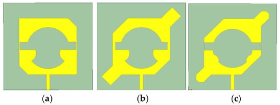
Figure 1.
Evolution of the proposed antenna: (a) Antenna 1; (b): Antenna 2; (c): Proposed Antenna.
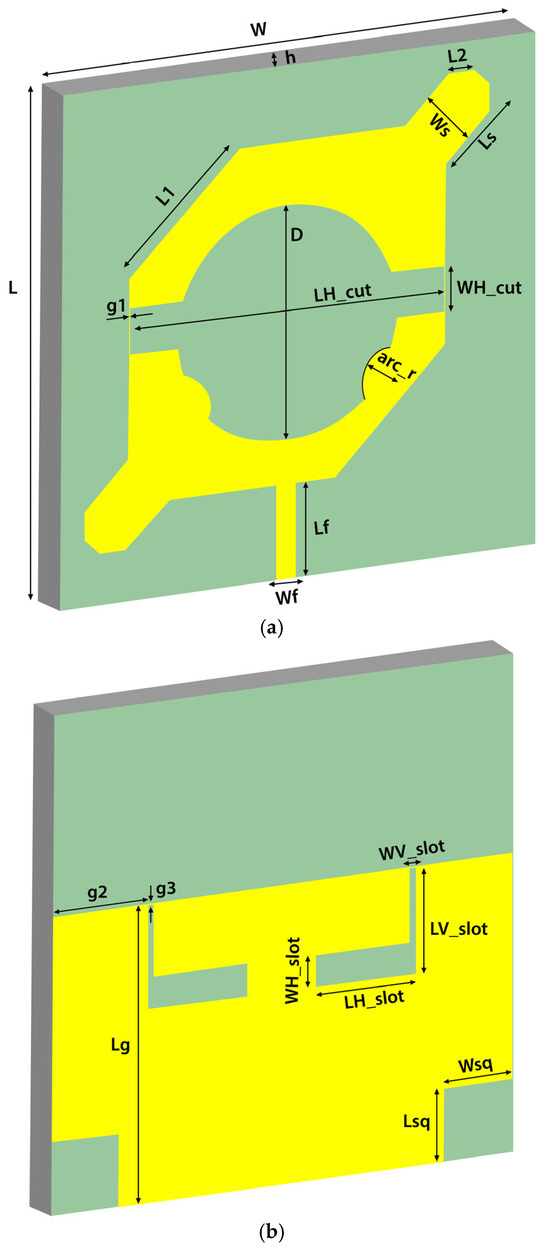
Figure 2.
(a) Top view and (b) bottom view of the proposed antenna.

Table 1.
Proposed optimal dimensions of the antenna in Figure 2.
The initial design began with a truncated squared patch. Then, the structure was modified to add two stubs on the other opposite corners. In the last step of this procedure, two arcs were added onto the lower edge of the centered circular cuts and the two added stubs were chamfered.
Table 1 displays the values of the geometrical parameters for the proposed antenna according to the definitions shown in Figure 2. The antenna has overall dimensions of 40 × 40 × 1.6 mm3 and was fabricated on an FR-4 substrate with a relative permittivity of εr = 4.4 and a loss tangent of 0.02. A 50 Ω transmission line with a signal strip width of Wf and a length of Lf was used to feed the antenna. Figure 3 shows the return loss response of the three antennas.
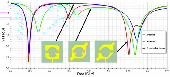
Figure 3.
Simulated return loss of Antenna 1, Antenna 2, and Proposed Antenna.
2.1. Circular Polarization
One of the effective techniques for achieving circular polarization in single-feed antennas is the use of truncated corners. This design approach helps to manipulate the current distribution across the antenna, enhancing its polarization characteristics. Among the three antenna configurations evaluated, the incorporation of rectangular stubs with chamfered corners proved particularly beneficial, successfully lowering the AR to below 3 dB at the desired operating bands.
Figure 4 illustrates the AR performance across the dual-band spectrum for the three antennas, highlighting the effects of the stubs on polarization. In the first antenna configuration, AR was significantly higher than the required threshold, indicating a lack of effective CP performance. Conversely, the second antenna configuration achieved AR values of 2.36 dB and 7.97 dB at frequencies of 3.39 GHz and 5.33 GHz, respectively, demonstrating improved polarization characteristics.
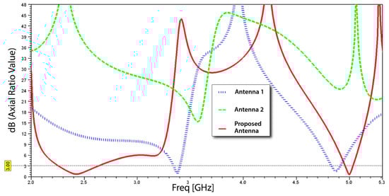
Figure 4.
Axial ratio versus frequency of the three antennas given in Figure 1.
However, adjustments are necessary for both operating bands to ensure that the AR remains below 3 dB, as seen in the first configuration. The incorporation of chamfered stubs in the proposed antenna design resulted in notable improvements, yielding AR values of 0.634 dB at 2.4 GHz and 0.974 dB at 5 GHz. These results underscore the effectiveness of the design modifications in meeting the AR requirements for optimal CP performance, thereby enhancing the antenna’s suitability for UAV applications. The findings clearly indicate that careful tuning of the antenna geometry is essential for achieving the desired polarization characteristics.
2.2. Parametric Analysis
After exhaustive simulation studies focusing on the antenna’s dimensions, practical lengths and positions were identified to optimize performance. Two merged cuts were responsible for creating the dual band at 2.45 and 5.0 GHz with the circular cut positioned at the 20 x-axis and 19.25 y-axis, and the horizontal rectangle at the 32.9 x-axis and 22 y-axis, with a small gap of g1 at both edges of the patch. On the bottom side, the optimum value for the length of the ground plane (Lg) is 24 mm and below this value it turns the response into the UWB, which is far from the operating band. The L-shaped slot starts from the gap below the edge of the ground plane at g3 and a distance from the right and left sides of g2. The parameters WV_slot and LH_slot affect return loss and gain especially at 2.4 GHz, whereas the parameters WH_slot and LV_slot affect return loss and gain at 5 GHz. The parameters Wsq and Lsq affect return loss and gain in dual-band operation. These slots are affected only in return loss and gain.
2.2.1. Dual-Band Response
Two essential parameters were identified: the diameter of the centered circular cut (D) and the dimensions of the centered rectangular cut, namely its length (LH_cut) and width (WH_cut). Comprehensive simulation studies indicated that the optimal diameter for the centered circular cut (D) should be 9 mm, which is an improvement over the 8 mm used in Antenna 1 and the 10 mm in Antenna 2. Furthermore, the length of the centered rectangular cut (LH_cut) was optimized to 25.8 mm, compared to 24.8 mm in Antenna 1 and 26.8 mm in Antenna 2. The width of the centered rectangular cut (WH_cut) was refined to 3.5 mm, compared to 2.5 mm in Antenna 1 and 4.5 mm in Antenna 2. These adjustments collectively enhance the antenna’s performance in achieving the desired response within the operating bands.
Changing the Parameter Element D
As illustrated in Figure 5, the design was simulated using various parametric values for (D), which denotes the diameter of the centered circular cut. It was noted that the response at 5 GHz varies significantly with alterations to this parameter. Specifically, when (D) is set to 9 mm, the response achieves optimal tuning. Further simulations indicated that reducing (D) to values below 9 mm resulted in a substantial leftward shift in the response. Conversely, increasing (D) beyond 9 mm caused the response to drop below 10 dB, adversely affecting the antenna’s overall efficiency. These observations highlight the critical role of precisely adjusting the diameter of the centered circular cut during the design process, as it not only impacts the response but also influences the overall performance of the antenna. By systematically optimizing (D) alongside other parameters, the design attains a robust configuration that effectively facilitates dual-band operation.
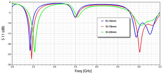
Figure 5.
Return loss of the parameter D.
Changing the Parameter Element LH_cut
As depicted in Figure 6, the design was simulated using various parametric values for (LH_cut), which indicates the length of the centered rectangular cut. It was found that the response at 2.4 GHz varies significantly with changes to this parameter. Specifically, when (LH_cut) is set to 25.8 mm, the response achieves optimal tuning. Further simulations revealed that reducing (LH_cut) to values below 25.8 mm caused both bands to shift rightward, introducing a new response at 3.83 GHz. Similarly, increasing (LH_cut) beyond 25.8 mm resulted in a minor shift and the emergence of a new response in the middle, which negatively affected the antenna’s overall efficiency. These results highlight the importance of meticulously adjusting the length of the centered rectangular cut during the design process, as it not only impacts the response but also has a cascading effect on the antenna’s overall performance. By systematically optimizing (LH_cut) along with other parameters, the design achieves a robust configuration that effectively supports dual-band operation.
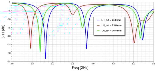
Figure 6.
Return loss of the parameter LH_cut.
Changing the Parameter Element WH_cut
As depicted in Figure 7, the design was simulated with various values for (WH_cut), which denotes the width of the centered rectangular cut. It was found that the response at 2.4 GHz varies significantly with changes to this parameter. Specifically, when (WH_cut) is set to 3.5 mm, the response is optimally tuned. Further simulations indicated that reducing (WH_cut) to below 3.5 mm caused both bands to shift slightly to the right. On the other hand, increasing (WH_cut) beyond 3.5 mm negatively affected the response at 5 GHz, which in turn reduced the antenna’s overall efficiency. These findings emphasize the necessity of carefully adjusting the width of the centered rectangular cut in the design process, as it influences the response and has a cascading effect on the antenna’s performance. By systematically optimizing (WH_cut) along with other parameters, the design achieves a strong configuration that effectively accommodates dual-band operation.
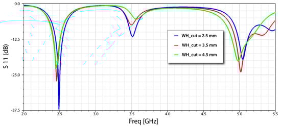
Figure 7.
Return loss of the parameter WH_cut.
These optimized values of the affected parameters ensure that the AR remains below 3 dB. Achieving a low AR is vital for promoting effective CP, which is important for various communication applications.
2.2.2. Axial Ratio
To achieve effective circular polarization in the proposed antenna design, three critical parameters were identified: the length of the truncated corners (L1), the width of the added rectangular stubs (Ws), and the diameter of the arc added to the lower edge of the circular slot on the top side (arc_r). Extensive simulation studies revealed that the practical length of the truncated corners (L1) should be 9 mm, which represents an improvement over the 7 mm utilized in Antenna 1 and 8.25 mm in Antenna 2. Correspondingly, the width of the added rectangular stubs (Ws) was optimized to 4.75 mm, compared to 5.75 mm in Antenna 1 and 4.5 mm in Antenna 2. For the diameter of the added (arc_r), the optimal centered position was determined to be at 10.75 on the x-axis and 13.475 on the y-axis, originating from the left corner of the design, with a diameter of 3 mm as an adjustment from the 4 mm used in Antenna 1 and 2.55 mm in Antenna 2. These refinements collectively enhance the antenna’s performance in achieving effective CP and broadening its operational capabilities.
Changing the Parameter Element L1
As shown in Figure 8, the design was simulated for different parametric values of (L1), which represents the length of the truncated corners. It was observed that the AR varies considerably with changes in this parameter. Specifically, when (L1) is set to 9 mm, the AR demonstrates optimal tuning across the entire established frequency range, indicating effective CP. Further simulations revealed that reducing (L1) to values below 9 mm resulted in a significant increase in the AR, exceeding the desired threshold of 3 dB, which compromised the antenna’s polarization performance. Conversely, increasing (L1) beyond 9 mm led to a narrower operating bandwidth and a less stable AR, which negatively impacted the antenna’s overall efficiency. These findings underscore the importance of fine-tuning the truncated corner lengths in the design process, as they not only influence the AR but also have a cascading effect on the overall antenna performance. By systematically optimizing (L1) along with other parameters, the design achieves a robust configuration that effectively supports dual-band operation while maintaining the integrity of CP.
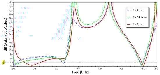
Figure 8.
Axial ratio versus frequency for different values of the parameter L1.
Changing the Parameter Element Ws
As shown in Figure 9, the design was simulated for different parametric values of (Ws), which represents the width of the two added stubs. It was observed that the AR varies considerably with changes in this parameter. Specifically, when (Ws) is set to 4.75 mm, the AR achieves optimal tuning across the entire established frequency range, indicating an effective CP performance. Further analysis revealed that decreasing (Ws) to values below 4.75 mm resulted in an undesirable increase in the AR, exceeding the target of 3 dB, which adversely affected the antenna’s ability to maintain consistent polarization. Conversely, increasing the width of the stubs beyond 4.75 mm led to a reduction in ARBW, highlighting the importance of precise tuning. These results emphasize the critical role of stub width in the overall antenna design process. By systematically varying (Ws) alongside other key parameters, the antenna can maintain a robust performance across dual-band operations while effectively supporting the requirements for CP. This fine-tuning approach ultimately enhances the antenna’s suitability for reliable communication in UAV applications.
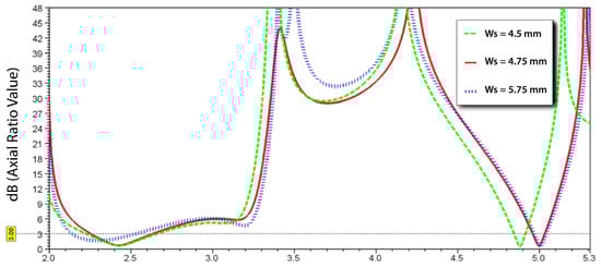
Figure 9.
Axial ratio versus frequency for different values of the parameter Ws.
Changing the Parameter Element arc_r
As shown in Figure 10, the design was simulated for different parametric values of (arc_r), which represents the diameter of the two added circular arcs. It was observed that the AR varies considerably with changes in this parameter. Specifically, when (arc_r) is set to 3 mm, the AR is finely tuned across the entire established frequency range, demonstrating effective CP characteristics. Further examination revealed that decreasing the diameter to values below 3 mm resulted in a sharp increase in the AR, often exceeding the critical 3 dB threshold, thereby compromising the antenna’s polarization performance. Conversely, increasing the diameter beyond 3 mm led to a broader bandwidth but at the cost of AR stability, indicating a trade-off that must be carefully managed during the design process. These findings underscore the significance of the diameter of the added arcs in the overall antenna design. By systematically adjusting (arc_r) in conjunction with other parameters, the antenna can achieve a balanced configuration that supports robust dual-band operation while ensuring effective CP. This careful tuning process ultimately enhances the antenna’s applicability for reliable communication in UAV environments.
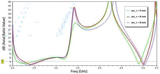
Figure 10.
Axial ratio versus frequency for different values of the parameter arc_r.
The surface current distribution of the final proposed antenna at various frequencies for both top and bottom sides is shown in Figure 11 and Figure 12. In Figure 11, it can be observed at 2.4 GHz that a considerable amount of surface current is distributed in the horizontal rectangular cut on the top side at 2.4 GHz, whereas on the bottom side it is on the upper side of the ground plane. In Figure 12, the surface current is distributed near the opposite truncated corners and edges of the centered circular cut on the top side at 5 GHz, whereas on the bottom side it is on the L-shaped cut.
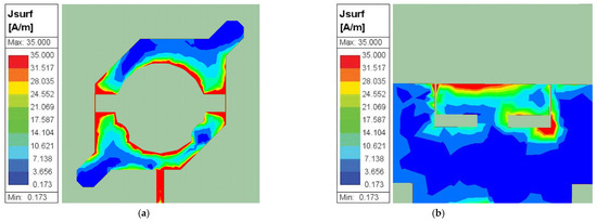
Figure 11.
Current distribution at 2.4 GHz: (a) top side; (b) bottom side.
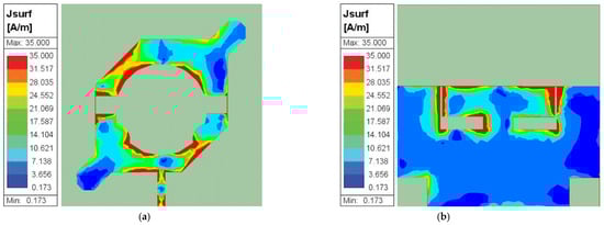
Figure 12.
Current distribution at 5 GHz: (a) top side; (b) bottom side.
In Figure 13, a 3D radiation pattern at 2.4 GHz and 5 GHz is presented for the designed antenna, illustrating maximum gains of 5.01 dBi and 5.27 dBi, respectively. These patterns reveal that the proposed antenna exhibits a commendable azimuthal coverage, indicating its ability to provide uniform radiation characteristics across the operational spectrum. This high gain, combined with favorable radiation patterns, suggests that the antenna is well suited for applications in UAVs where reliable communication is crucial. The high gain observed at both frequencies indicates that the antenna can effectively transmit and receive signals over extended distances, making it particularly advantageous for UAV applications involved in remote sensing, surveillance, and data transmission. Additionally, the ability to maintain good radiation characteristics in varying orientations enhances the antenna’s robustness in real-world environments.
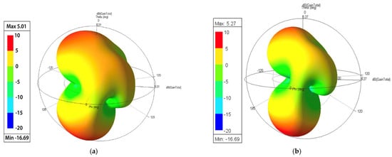
Figure 13.
Three-dimensional radiation patterns of maximum gains of (a) 5.01 dBi at 2.4 GHz and (b) 5.27 dBi at 5 GHz.
3. Experimental Validation
To validate the simulation results, a prototype of the proposed antenna was fabricated based on the optimized parameters listed in Table 1. Figure 14 displays the fabricated antenna, with dimensions of 40 × 40 × 1.6 mm3, confirming its compact design. The reflection coefficient and other performance parameters were measured and evaluated using an Agilent N5247A network analyzer.
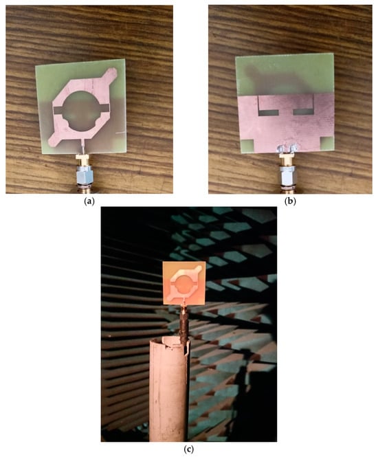
Figure 14.
Manufacture of the proposed antenna: (a) top side; (b) bottom side; (c) measurement setup.
Figure 15 shows the simulated return loss compared with the measurements. It is clearly shown that there is a good agreement between the simulated and measured results.
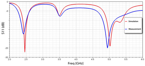
Figure 15.
Simulated and measured S-parameter.
This correlation reinforces the accuracy of the simulation model and the effectiveness of the design approach. The simulated frequency bandwidths for |S11| < −10 dB were found to be 124 MHz (from 2.396 to 2.52 GHz) and 470 MHz (from 4.91 to 5.38 GHz), while the measured frequency bandwidths for |S11| < −10 dB were found to be 210 MHz (from 2.32 to 2.53 GHz) and 450 MHz (from 4.8 to 5.25 GHz). The measured results validate the enhancements achieved through the design modifications, such as the incorporation of truncated corners and stubs, which contribute to improved bandwidth and gain.
Figure 16 and Figure 17 illustrate the simulation and measurement of AR and radiation patterns for the proposed antenna. The radiation characteristics of the fabricated antenna were evaluated in an RF anechoic chamber, which provides a controlled environment free from external interference, ensuring accurate measurement results. From Figure 16, it is found that the 3 dB ARBW were 13.80% (2.3 to 2.64 GHz) and 2.6% (5 to 5.08 GHz) in both simulations and measurements. Importantly, the 3 dB ARBW is fully encompassed within the −10 dB reflection bandwidth, confirming the antenna’s effective operation across the specified frequency ranges. The normalized radiation patterns, both simulated and measured, at 2.4 GHz and 5 GHz are presented in Figure 17 for the principal planes: the planes and the plane. The proposed antenna demonstrates substantial E-plane radiation directed toward the z direction, indicating its capability for effective communication in this orientation. Additionally, the radiation patterns at 5 GHz exhibit an asymmetric distribution, tilting away from the broadside direction, suggesting that the design features positively influence the antenna’s radiation characteristics.
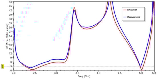
Figure 16.
Simulated and measured axial ratio versus frequency.
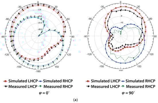
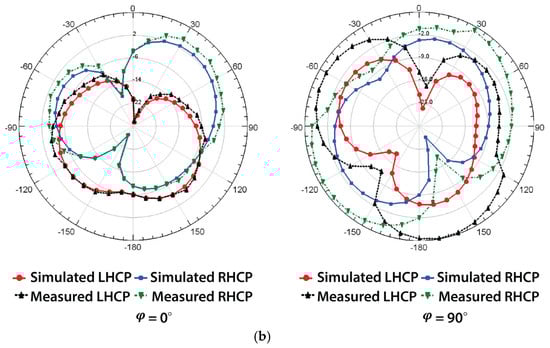
Figure 17.
Simulated and measured radiation patterns at (a) 2.4 GHz (LHCP and RHCP) and (b) 5 GHz (LHCP and RHCP).
4. Discussion
A comparison of the previous works with the proposed antenna is shown in Table 2. The antenna presented in [9], operating at WLANs, achieved CP using a pair of rectangular slots along the diagonal line, giving gains of 2.51 dBi and 3.51 dBi at 2.4 GHz and 3.51 GHz, respectively, and an antenna size of 40 × 54 mm2. The antenna mentioned in [10] achieved dual-band CP using truncated corners with a slant strip line and an L-shaped slot for WLAN applications, giving gains of 5.01 dBi and 5.27 dBi, respectively, at 2.45 GHz and 5 GHz with a size of 40 × 47 mm2. The antenna developed in [11] achieved CP under dual-band operation by adding two shaped strips, C and L, which are responsible for the higher and lower bands; this antenna gave a gain of 7.29 dBi with a size of 50 × 50 m2. The antenna proposed in [12] used the concept of dual-band based on a two-layer stacked patch for GPS and WiFi purposes, and the antenna size of 56 × 56 m2 gave gains of 4.22 dBi at 1.23 GHz and 2.39 dBi at 2.42 GHz. The antenna discussed in [23], operating at the S-band with a size of 170 × 170 m2, gave gains of 5.14 dBi at 2.4 GHz and 4.50 dBi at 5.8 GHz. From Table 2, it can be seen that the proposed antenna provides a higher gain with a relatively reduced size. It can be concluded that the proposed smaller antenna has good radiation properties and a simple feeding network.
Table 2.
Comparison between the proposed antenna and different structures presented in the literature.
5. Conclusions
In this paper, a novel dual-band circular polarized microstrip patch antenna for UAV applications was developed and characterized. The antenna, with compact dimensions of 40 × 40 × 1.6 mm3, demonstrates effective performance across the WiFi frequency bands of 2.4 GHz and 5 GHz. Key features of the design, including the implementation of truncated corners and strategically placed stubs, contribute to the antenna’s ability to achieve a low AR and enhanced bandwidth. Our simulation results indicated a 3 dB ARBW of 13.88% at 2.4 GHz and 2% at 5 GHz, both of which align well with the measured results obtained from the fabricated prototype. Measurements conducted on a physical realization of the design in an RF anechoic chamber revealed good agreement with the simulation data, confirming the antenna’s performance and validating the design approach. The effective radiation patterns exhibited by the antenna suggest its suitability for reliable communication in dynamic UAV environments. The findings highlight the importance of precise design parameters, such as the width of stubs and the diameter of cuts, in optimizing both the AR and gain. Overall, this research contributes to the advancement of antenna technology for UAVs, providing a solid foundation for future developments. Further optimization and refinement of the design could lead to even greater enhancements in performance, potentially extending the antenna’s applicability to a wider range of wireless communication systems. The current design focuses on two frequency bands (2.4 GHz and 5 GHz), and expanding this range to include additional communication standards could enhance versatility. By addressing these limitations, future research can improve the antenna’s robustness and adaptability for UAV applications.
Author Contributions
Conceptualization, A.S.A. and R.W.A.; methodology, A.S.A. and R.W.A.; software, A.S.A.; validation, A.S.A. and R.W.A.; formal analysis, A.S.A.; investigation, A.S.A.; writing—original draft preparation, A.S.A.; writing—review and editing, R.W.A.; visualization, A.S.A.; supervision, R.W.A.; project administration, R.W.A. All authors have read and agreed to the published version of the manuscript.
Funding
This research received no external funding.
Institutional Review Board Statement
Not applicable.
Informed Consent Statement
Not applicable.
Data Availability Statement
Data are contained within the article.
Conflicts of Interest
The authors declare no conflicts of interest.
References
- Yang, Y.-L.; Lin, D.-B. A Compact Planar Wi-Fi Antenna with Optimized Radiation Patterns for Small UAV Applications. Appl. Sci. 2023, 13, 7470. [Google Scholar] [CrossRef]
- Widhalm, P.; Ritzinger, U.; Prüggler, N.; Prüggler, W.; Strelnikova, D.; Paulus, G.; D’apolito, F.; Eicken, F. Community Drones: A Concept Study on Shared Drone Services. Drones 2025, 9, 107. [Google Scholar] [CrossRef]
- Nguyen, M.T.; Nguyen, C.V.; Do, H.T.; Hua, H.T.; Tran, T.A.; Nguyen, A.D.; Ala, G.; Viola, F. UAV-assisted data collection in wireless sensor networks: A comprehensive survey. Electronics 2021, 10, 2603. [Google Scholar] [CrossRef]
- Gómez, L.; Ibrahim, A.S. Design, Analysis and Simulation of Microstrip Antenna Arrays with Flexible Substrate in Different Frequency, for Use in UAV-Assisted Marine Communications. J. Mar. Sci. Eng. 2023, 11, 730. [Google Scholar] [CrossRef]
- Rahardjo, E.T.; Zulkifli, F.Y.; Herwanto, D.Y.; Basari; Sri Sumantyo, J.T. Circular polarization Microstrip Antenna Array for UAV Application. In Proceedings of the International Symposium on Antennas & Propagation, Nanjing, China, 23–25 October 2013; pp. 870–872. Available online: https://ieeexplore.ieee.org/document/6717620/metrics#metrics (accessed on 10 January 2025).
- Wang, D.; Wang, M.; Xu, N.; Wu, W. Improved Measurement Method of Circularly-Polarized Antennas Based on Linear-Component Amplitudes. Open J. Antennas Propag. 2017, 5, 36–45. [Google Scholar] [CrossRef]
- Kandregula, V.R.; Zaharis, Z.D.; Ahmed, Q.Z.; Khan, F.A.; Loh, T.H.; Schreiber, J.; Serres, A.J.R.; Lazaridis, P.I. A Review of Unmanned Aerial Vehicle Based Antenna and Propagation Measurements. Sensors 2024, 24, 7395. [Google Scholar] [CrossRef]
- Ali, S.; Abu-Samah, A.; Abdullah, N.F.; Kamal, N.L.M. Propagation Modeling of Unmanned Aerial Vehicle (UAV) 5G Wireless Networks in Rural Mountainous Regions Using Ray Tracing. Drones 2024, 8, 334. [Google Scholar] [CrossRef]
- Ray, M.K.; Mandal, K. Pair of diagonal slots loaded low-profile circularly polarised patch antenna with wide 3 dB axial ratio beamwidth. IET Microwaves Antennas Propag. 2019, 13, 2433–2438. [Google Scholar] [CrossRef]
- Niyamanon, S.; Senathong, R.; Phongcharoenpanich, C. Dual-Frequency Circularly Polarized Truncated Square Aperture Patch Antenna with Slant Strip and L-Shaped Slot for WLAN Applications. Int. J. Antennas Propag. 2018, 2018, 7684742. [Google Scholar] [CrossRef]
- Tan, M.-T.; Wang, B.-Z. A Dual-Band Circular polarization Planar Monopole Antenna for WLAN/Wi-Fi Applications. IEEE Antennas Wirel. Propag. Lett. 2015, 15, 670–673. [Google Scholar] [CrossRef]
- Oo, W.M.; Tun, H.M.; Nway, T.M.; Pradhan, D.; Sahu, P.K.; Naing, Z.M. Design, Analysis and Fabrication of Dual Band Microstrip Patch Antenna for (L2) Band GPS and WiFi Applications. In Proceedings of the 2022 International Conference for Advancement in Technology (ICONAT), Goa, India, 21–22 January 2022; pp. 1–5. [Google Scholar]
- Jin, H.; Han, C.-Z.; Fu, Y.; Yang, H. A Low-Profile Dual-Band Directional Antenna for Unmanned Aerial Vehicle Applications. Int. J. Antennas Propag. 2022, 2022, 4765008. [Google Scholar] [CrossRef]
- Trinh-Van, S.; Yang, Y.; Lee, K.-Y.; Kim, Y.S.; Hwang, K.C. Bandwidth-enhanced circular polarization crescent-shaped slot antenna via circular-patch loading. Appl. Sci. 2019, 9, 1117. [Google Scholar] [CrossRef]
- Liu, X.; Wang, H.; Yang, X.; Wang, J. Quad-Band Circular Polarized Antenna for GNSS, 5G and WIFI-6E Applications. Electronics 2022, 11, 1133. [Google Scholar] [CrossRef]
- Raza, M.U.; Ren, H.; Yan, S. Dual-Band Monopole MIMO Antenna Array for UAV Communication Systems. Sensors 2024, 24, 5913. [Google Scholar] [CrossRef] [PubMed]
- Yang, X.; Qi, Y.; Yuan, B.; Cao, Y.; Wang, G. A Miniaturized High-Gain Flexible Antenna for UAV Applications. Int. J. Antennas Propag. 2021, 2021, 9919425. [Google Scholar] [CrossRef]
- Liu, N.; Zhu, L.; Choi, W. Low-profile wide-beamwidth circularly-polarised patch antenna on a suspended substrate. IET Microwaves Antennas Propag. 2016, 10, 885–890. [Google Scholar] [CrossRef]
- Telli, K.; Kraa, O.; Himeur, Y.; Ouamane, A.; Boumehraz, M.; Atalla, S.; Mansoor, W. A Comprehensive Review of Recent Research Trends on Unmanned Aerial Vehicles (UAVs). Systems 2023, 11, 400. [Google Scholar] [CrossRef]
- Laghari, A.A.; Jumani, A.K.; Laghari, R.A.; Nawaz, H. Unmanned aerial vehicles: A review. Cogn. Robot. 2022, 3, 8–22. [Google Scholar] [CrossRef]
- Li, X.-P.; He, C.-L.; Ji, J.-F.; Yang, M.-B.; Zhang, Y.; Zhang, A.-X.; Li, W. A Compact Broadband Common-Aperture Dual-Polarized Antenna for Drone Applications. Micromachines 2024, 16, 48. [Google Scholar] [CrossRef]
- Liu, J.; Yu, Y.; Zeng, Y.; Yang, X. Design of a Dual Frequency Circular Polarized Microstrip Antenna. In Proceedings of the 2019 International Conference on Wireless Communication, Network and Multimedia Engineering (WCNME 2019), Guilin, China, 21–22 April 2019. [Google Scholar]
- Kurniawan, F.; Sumantyo, J.T.S.; Gao, S.; Ito, K.; Santosa, C.E. Square-shaped feeding truncated circularly polarised slot antenna. IET Microwaves Antennas Propag. 2018, 12, 1279–1286. [Google Scholar] [CrossRef]
- Mira, F.; Artiga, X.; Llamas-Garro, I.; Vázquez-Gallego, F.; Velázquez-González, J.S. Circularly Polarized Dual-Band LoRa/GPS Antenna for a UAV-Assisted Hazardous Gas and Aerosol Sensor. Micromachines 2021, 12, 377. [Google Scholar] [CrossRef]
- Xiao, Y.; He, L.; Wei, X. Dual-Band Dual-Circularly Polarized Shared-Aperture Phased Array for S-/C-Band Satellite Communications. Electronics 2025, 14, 387. [Google Scholar] [CrossRef]
- Mohammed, A.H.; Alnahwi, F.M.; Al-Yasir, Y.I.A. A Circularly Polarized Microstrip Antenna with Dual Circular Polarization Using a 90° Hybrid Coupler and Proximity-Coupled Feeding for LTE 43 5G Applications. Appl. Sci. 2024, 14, 11877. [Google Scholar] [CrossRef]
- Song, Z.; Xu, X.; Shi, Y.; Wang, L. Design of a Compact Circularly Polarized Implantable Antenna for Capsule Endoscopy Systems. Sensors 2024, 24, 3960. [Google Scholar] [CrossRef] [PubMed]
- Lee, T.-H.; Jung, J.; Pyo, S. Circularly Polarized 4 × 4 Array Antenna with a Wide Axial Ratio Bandwidth. Electronics 2024, 13, 2076. [Google Scholar] [CrossRef]
- Chen, Q.; Yang, J.; He, C.; Zhang, D.; Huang, S.; Wang, M.; Yu, F.; Dai, G. Wideband Circularly Polarization and High-Gain of a Slot Patch Array Antenna Realized by a Hybrid Metasurface. Sensors 2024, 24, 3510. [Google Scholar] [CrossRef]
- Liu, X.; Liu, H.; Zheng, K.; Liu, J.; Taleb, T.; Shiratori, N. AoI-Minimal Clustering, Transmission and Trajectory Co-Design for UAV-Assisted WPCNs. IEEE Trans. Veh. Technol. 2024, 74, 1035–1051. [Google Scholar] [CrossRef]
- Miklavčič, P.; Batagelj, B. A New Sum-Channel Radiating Element for a Patch-Monopole Monopulse Feed. Electronics 2024, 13, 3187. [Google Scholar] [CrossRef]
- Ansys Inc. 3D High Frequency Simulation Software, ANSYS HFSS. 2017. Available online: http://www.ansys.com (accessed on 2 December 2024).
Disclaimer/Publisher’s Note: The statements, opinions and data contained in all publications are solely those of the individual author(s) and contributor(s) and not of MDPI and/or the editor(s). MDPI and/or the editor(s) disclaim responsibility for any injury to people or property resulting from any ideas, methods, instructions or products referred to in the content. |
© 2025 by the authors. Licensee MDPI, Basel, Switzerland. This article is an open access article distributed under the terms and conditions of the Creative Commons Attribution (CC BY) license (https://creativecommons.org/licenses/by/4.0/).