

Fluorinated Polymers for Photonics—From Optical Waveguides to Polymer-Clad Glass Optical Fibers


Abstract
Featured Application
Abstract
1. Introduction
2. Fluorinated Polymers for Passive Optical Waveguides
2.1. Material Based on a Halogenated Acrylate Mixture
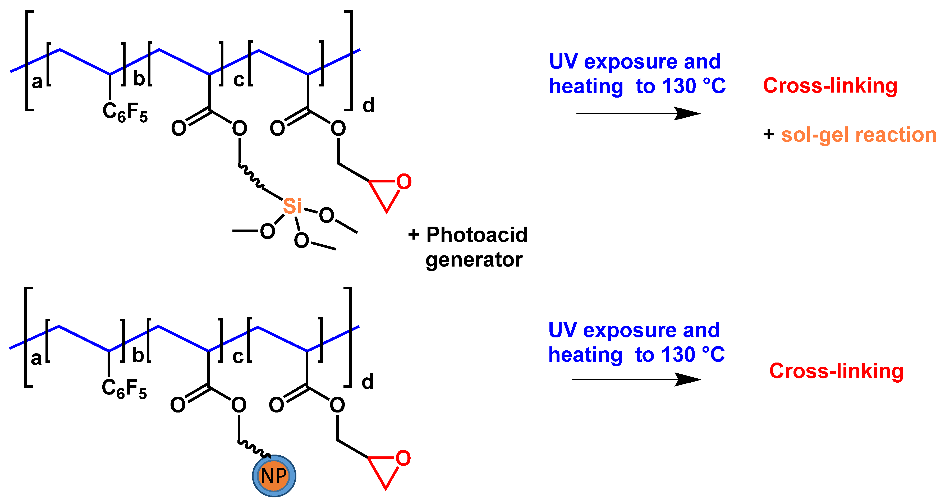
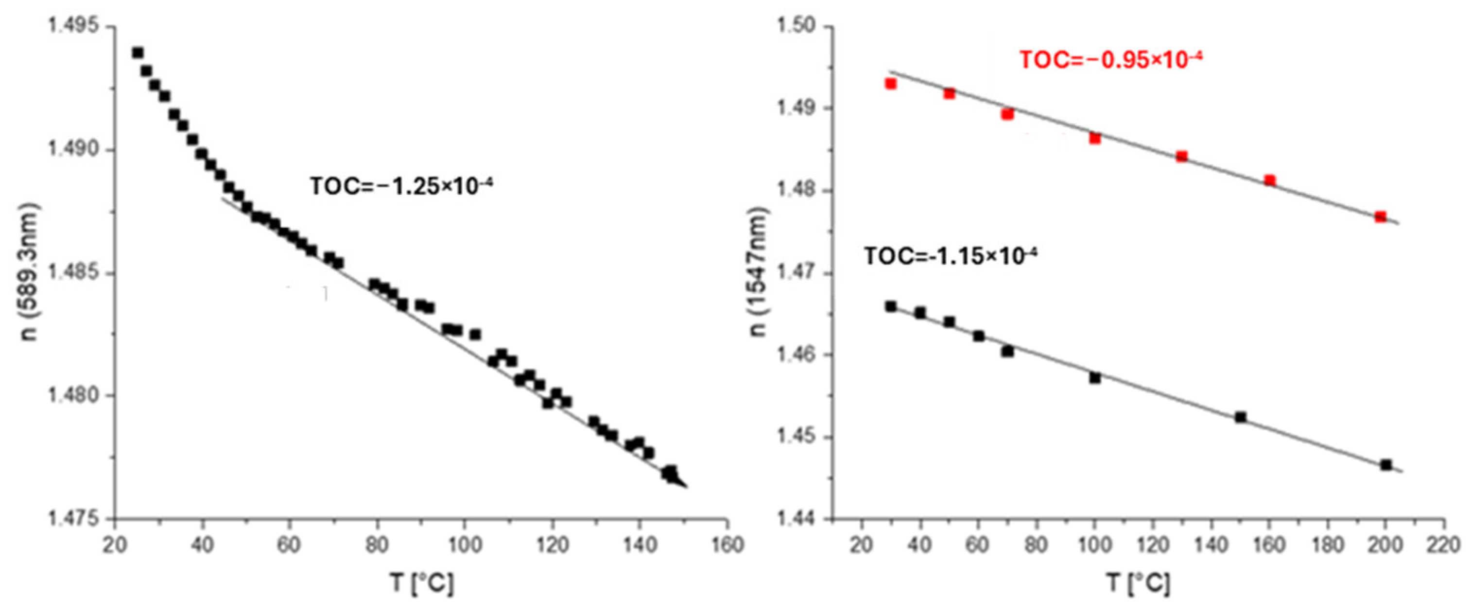
2.2. Glycidyl-Containing Polymer Materials
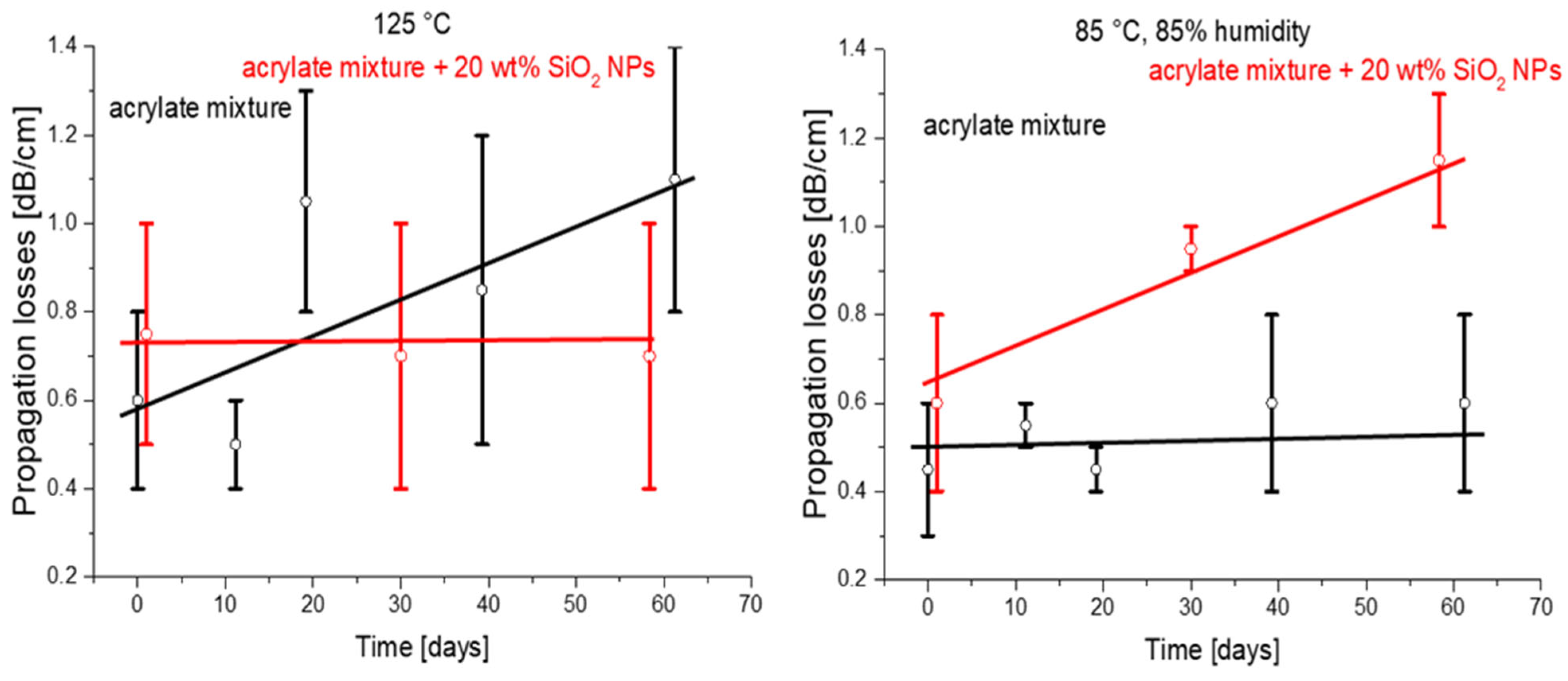
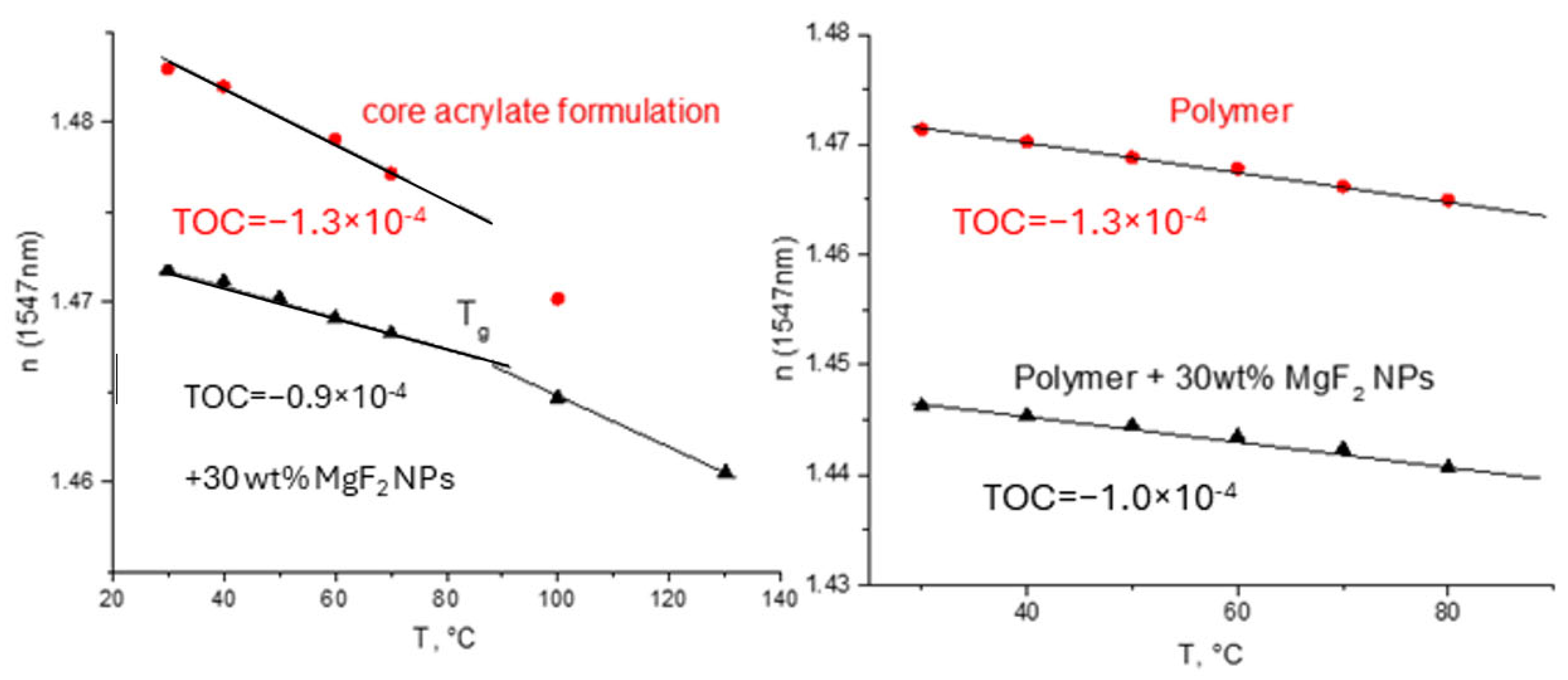
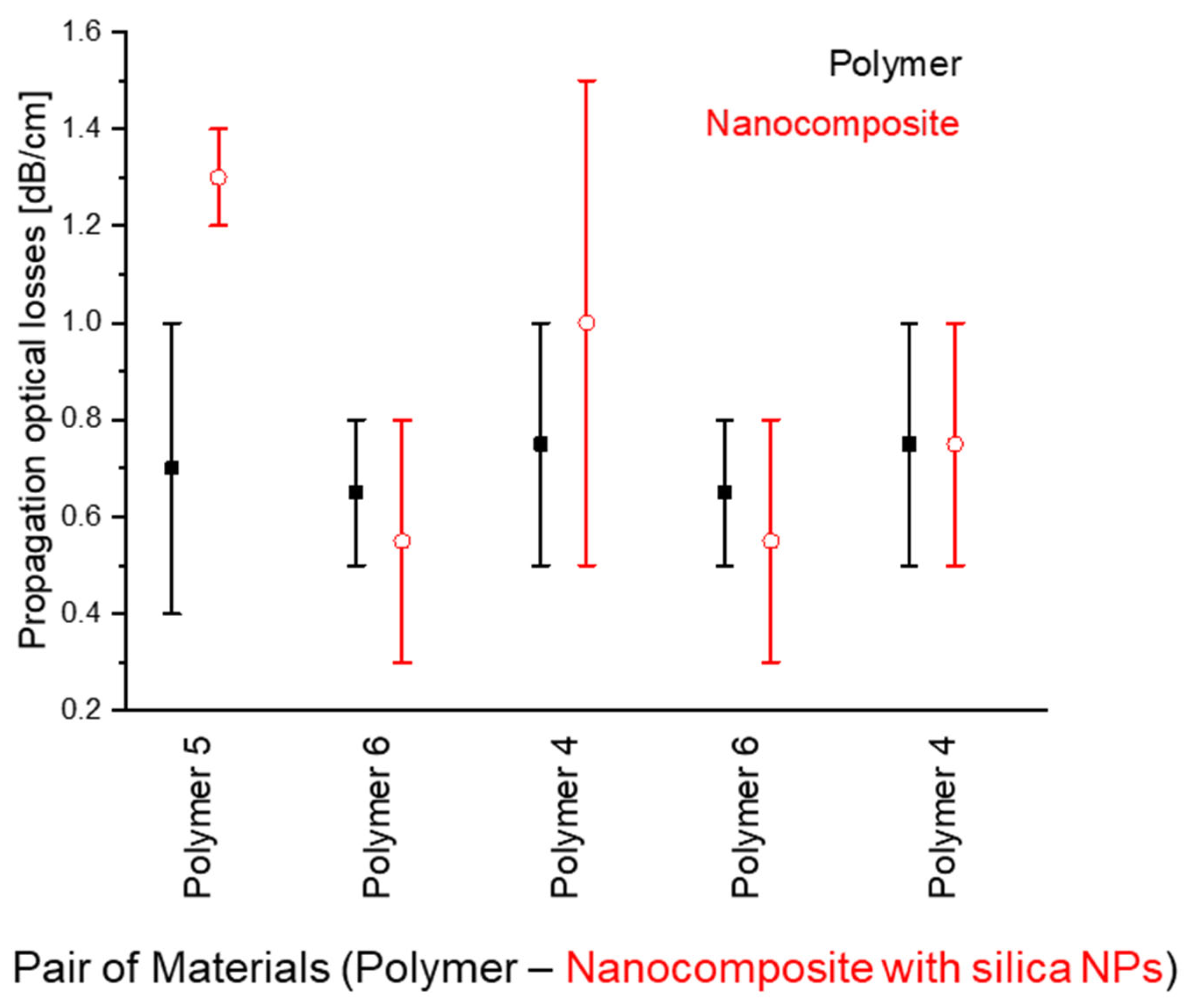
2.3. Composite Waveguiding Materials Containing SiO2 and MgF2 Nanoparticles
3. Fluorinated Polymers as Cladding for Optical Glass Fibers
4. Conclusions
Author Contributions
Funding
Data Availability Statement
Conflicts of Interest
References
- Goldenberg, L.M.; Köhler, M.; Kahle, O.; Dreyer, C. Impact of inorganic nanoparticles on optical properties of low refractive index waveguiding polymers. Optic. Mater. Expr. 2020, 10, 2987–2997. [Google Scholar] [CrossRef]
- Goldenberg, L.M.; Köhler, M.; Dreyer, C. SiO2 Nanoparticles-Acrylate Formulations for Core and Cladding in Planar Optical Waveguides. Nanomaterials 2021, 11, 1210. [Google Scholar] [CrossRef] [PubMed]
- Goldenberg, L.M.; Köhler, M.; Dreyer, C.; Krahl, T.; Kemnitz, E. Optical nanocomposites containing low refractive index MgF2 nanoparticles. Eur. Phys. J. Appl. Phys. 2021, 94, 10403. [Google Scholar] [CrossRef]
- Köhler, M.; Goldenberg, L.M.; Pithart, C.; Dreyer, C. UV-Curable Thermosetting Polymers for (Optical) Coatings and Photonics. In Proceedings of the 2017 RadTech Europe Conference & Exhibition 2017, Prague, Czech Republic, 17–19 October 2017. [Google Scholar]
- Dreyer, C.; Köhler, M.; Schrader, S.; Yao, H. Chapter 9—Fluorinated thermosetting resins for photonic applications. In Fascinating Fluoropolymers and Their Applications; Ameduri, B., Fomin, S., Eds.; Elsevier: Amsterdam, The Netherlands, 2020; pp. 269–335. [Google Scholar] [CrossRef]
- Dreyer, C.; Motoc, D.L.; Köhler, M.; Goldenberg, L. UV LED Curable Perfluoropolyether (PFPE)-Urethane Methacrylate Transparent Coatings for Photonic Applications: Synthesis and Characterization. Polymers 2023, 15, 2983. [Google Scholar] [CrossRef] [PubMed]
- Ziemann, O.; Krauser, J.; Zamzow, P.E.; Daum, W. POF-Handbuch: Optische Kurzstrecken-Übertragungssysteme; Springer: Berlin/Heidelberg, Germany, 2008; pp. 155–189. [Google Scholar]
- Toray: Technical Bulletin—Toray Polymer Optical Fiber Cord, Typ: PF, PG, PHK. Available online: https://easypdfs.cloud/downloads/4919257-Technical%20Data%20Sheet%20Toray (accessed on 7 December 2024).
- Leoni Fiber-Optics Katalog. 168p. Available online: https://pdf.directindustry.de/pdf/leoni-ag/lichtwellenleiter-kabel/14158-24334.html (accessed on 7 December 2024).
- Watanabe, T.; Ooba, N.; Hida, Y.; Hikita, M. Influence of humidity on refractive index of polymers for optical waveguide and its temperature dependence. Appl. Phys. Lett. 1998, 72, 1533–1535. [Google Scholar] [CrossRef]
- Usui, M.; Hikita, M.; Watanabe, T.; Amano, M.; Sugawara, S.; Hayashida, S.; Imamura, S. Low-loss passive polymer optical waveguides with high environmental stability. J. Lightwave Technol. 1996, 14, 2338–2343. [Google Scholar] [CrossRef]
- Mizuno, H.; Sugihara, O.; Kaino, T.; Okamoto, N.; Hosino, M. Low-loss polymeric optical waveguides with large cores fabricated by hot embossing. Opt. Lett. 2003, 28, 2378–2380. [Google Scholar] [CrossRef]
- Ma, H.; Yen, A.K.-Y.; Dalton, L.R. Polymer-Based Optical Waveguides: Materials, Processing, and Devices. Adv. Mater. 2002, 14, 1339–1365. [Google Scholar] [CrossRef]
- Zhang, Z.; Zhao, P.; Lin, P.; Sun, F. Thermo-optic coefficients of polymers for optical waveguide applications. Polymer 2006, 47, 4893–4896. [Google Scholar] [CrossRef]
- Kane, C.F.; Krchnavek, R.R. Benzocyclobutene optical waveguides. IEEE Photonics Technol. Lett. 1995, 7, 535–537. [Google Scholar] [CrossRef]
- Smith, D.W.; Chen, S.; Kumar, S.M.; Ballato, J.; Topping, C.; Shah, H.V.; Foulger, S.H. Perfluorocyclobutyl copolymers for microphotonics. Adv. Mater. 2002, 14, 1585–1589. [Google Scholar] [CrossRef]
- Ballato, J.; Foulger, S.H.; Smith, D.W., Jr. Optical properties of perfluorocyclobutyl polymers. II. Theoretical and experimental attenuation. JOSA B 2004, 21, 958–967. [Google Scholar] [CrossRef]
- Jin, J.; Topping, C.M.; Chen, S.; Ballato, J.; Foulger, S.H.; Smith, D.W. Synthesis and comparison of CF3 versus CH3 substituted perfluorocyclobutyl (PFCB) networks for optical applications. J. Polym. Sci. A 2004, 42, 5292–5300. [Google Scholar] [CrossRef]
- Aharoni, S.M. Fluoropolymers and Fluoropolymer Coatings. US Patent No. 5183839, 16 September 1991. [Google Scholar]
- Dreyer, C.; Schneider, J.; Göcks, K.; Beuster, B.; Bauer, M.; Keil, N.; Yao, H.H.; Zawadzki, C. New Reactive Polymeric Systems for Use as Waveguide Materials in Integrated Optics. Macromol. Symp. 2003, 199, 307–319. [Google Scholar] [CrossRef]
- Dreyer, C.; Frommberger, M. Thermosets for Optical Applications—An Overview with Selected Examples. Thermosets 2009, from Monomers to components. Micromater. Nanomater. 2009, 11, 46–51. [Google Scholar]
- Watanabe, T.; Ooba, N.; Hayashida, S.; Kurihara, T.; Imamura, S. Polymeric optical waveguide circuits formed using silicone resin. J. Lightwave Technol. 1998, 16, 1049. [Google Scholar] [CrossRef]
- Toyoda, S.; Ooba, N.; Hikita, M.; Kurihara, T.; Imamura, S. Propagation loss and birefringence properties around 1.55 μm of polymeric optical waveguides fabricated with cross-linked silicone. Thin Solid Films 2000, 370, 311–314. [Google Scholar] [CrossRef]
- Buestrich, R.; Kahlenberg, F.; Popall, M.; Dannberg, P.; Müller-Fiedler, R.; Rösch, O. ORMOCER® s for optical interconnection technology. J. Sol-Gel Sci. Technol. 2001, 2, 181–186. [Google Scholar] [CrossRef]
- Available online: http://www.chemoptics.co.kr/en/sub/technical/data.php?mode=view&inSeq=6& (accessed on 7 December 2024).
- Zhang, Z.; Mettbach, N.; Zawadzki, C.; Wang, J.; Schmidt, D.; Brinker, W.; Grote, N.; Schell, M.; Keil, N. Polymer-based photonic toolbox: Passive components, hybrid integration and polarisation control. IET Optoelectron. 2011, 5, 226–232. [Google Scholar] [CrossRef]
- Zawadzki, C.; Schirmer, M. Der Wellenleiter-Chip—Photonische Bauelemente aus Polymeren. Photonik 2018, 1, 43. [Google Scholar]
- Prajzler, V.; Jasek, P.; Nekvindova, P. Inorganic–organic hybrid polymer optical planar waveguides for micro-opto-electro-mechanical systems (MOEMS). Microsyst. Technol. 2019, 25, 2249–2258. [Google Scholar] [CrossRef]
- Noack, J.; Fritz, C.; Flügel, C.; Hemmann, F.; Gläsel, H.-J.; Kahle, O.; Dreyer, C.; Bauer, M.; Kemnitz, E. Metal fluoride-based transparent nanocomposites with low refractive indices. Dalton Trans. 2013, 42, 5706–5710. [Google Scholar] [CrossRef] [PubMed]
- Noack, J.; Schmidt, L.; Gläsel, H.-J.; Bauer, M.; Kemnitz, E. Inorganic–organic nanocomposites based on sol–gel derived magnesium fluoride. Nanoscale 2011, 3, 4774–4779. [Google Scholar] [CrossRef] [PubMed]
- Zou, H.; Wu, S.; Shen, J. Polymer/Silica Nanocomposites: Preparation, Characterization, Properties, and Applications. Chem. Rev. 2008, 108, 3893–3957. [Google Scholar] [CrossRef]
- Hougham, G.G.; Cassidy, P.E.; Johns, K.; Davidson, T. (Eds.) Fluoropolymers 1: Synthesis; Kluwer Academic Publishers: New York, NY, USA; Boston, MA, USA; Dordrecht, The Netherlands; London, UK; Moscow, Russia, 2002; 330p. [Google Scholar]
- Noack, J.; Emmerling, F.; Kirmse, H.; Kemnitz, E. Sols of nanosized magnesium fluoride: Formation and stabilisation of nanoparticles. J. Mater. Chem. 2011, 21, 15015–15021. [Google Scholar] [CrossRef]
- Chemtob, A.; Versace, D.-L.; Belon, C.; Croutxé-Barghorn, C.; Rigolet, S. Concomitant organic− inorganic UV-curing catalyzed by photoacids. Macromolecules 2008, 41, 7390–7398. [Google Scholar] [CrossRef]
- Chang, S.; Lee, D.; Oh, J. UV-Curable Resin Composition for Cladding Optical Fiber. U.S. Patent No. US 2006/0067638 A1, 16 May 2006. [Google Scholar]
- Bishop, T.; Gan, G. LED Curing of Radiation Curable Optical Fiber Coating Compositions. U.S. Patent No. WO 2011/075549, 23 June 2011. [Google Scholar]
- Treloar, L.G.R. The Physics of Rubber Elasticity; Oxford University Press: New York, NY, USA, 1975. [Google Scholar]


| Polymer Material | Propagation Loss at 1547 nm, dB·cm−1 | TOC, ×10−4 K−1 |
|---|---|---|
| Monomer materials based on acrylates, core (n = 1.48 and 1.5) | 0.3–0.6 | −(1.3–1.5) |
| Monomer materials based on acrylates, cladding (n = 1.45) | 0.4–0.5 | −(1.3–1.5) |
| Glycidyl-containing polymer, core (n = 1.48 and 1.5) | 0.5–0.7 | −(0.65–0.85) |
| Glycidyl-containing polymer, cladding (n = 1.45) | 0.6–0.8 | −(0.8–1.0) |
| Monomer mixtures + SiO2 NP dispersions in solvents | 0.2–1.0 | −(0.6–1.0) |
| Monomer mixtures + SiO2 NP dispersions in acrylates | 0.3–0.4 | −(0.8–1.5) |
| Monomer mixtures + MgF2 NPs | 1.7–2.5 | −0.9 |
| Glycidyl-containing polymer + MgF2 NPs | - | −1.0 |
| Glycidyl-containing polymer + SiO2 NP dispersions in solvents | 0.5–1.0 | −(0.55–1.25) |
| Glycidyl-containing polymer containing SiO2 NPs in chain | - | −(1.1–1.3) |
| Glycidyl-containing polymer containing SiO2 NPs formed in situ | - | −(0.95–1.15) |
| Reference material, ChemOptics [25] | 0.35 | −(1.5–2.2) |
| No. * | Resin | Viscosity [mPas, 26 °C] | Refractive Index (20 °C) | ||||
|---|---|---|---|---|---|---|---|
| 400.0 nm | 486.1 nm | 598.3 nm | 653.0 nm | 704.0 nm | |||
| 1 | Low-index reference from j-fiber | 3088.89 | 1.4074 | 1.3991 | 1.3940 | 1.3920 | 1.3908 |
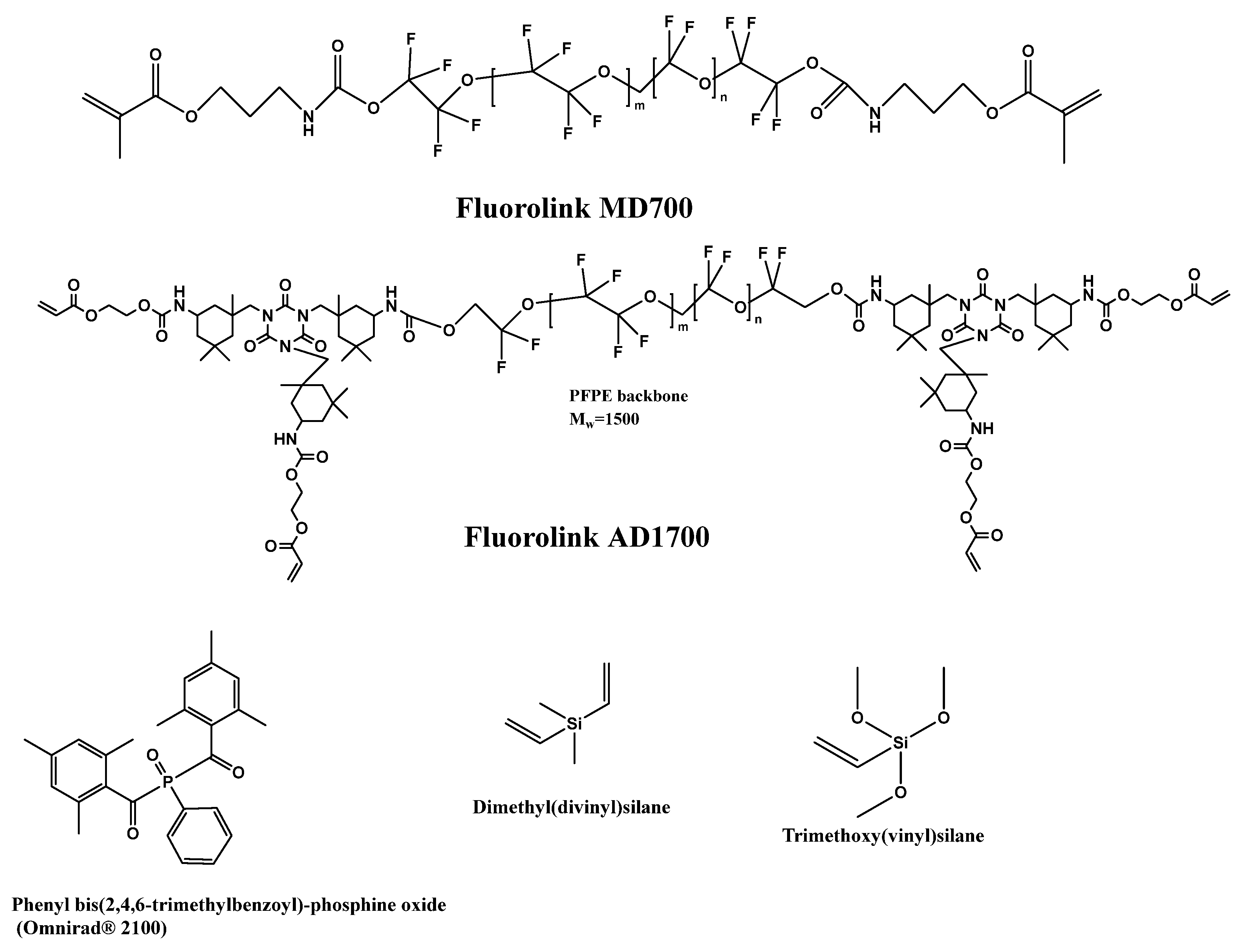
| 2 | Fluorolink AD 1700 | 22,440.00 | 1.4428 | 1.4337 | 1.4281 | 1.4259 | 1.4246 |
| 3 | Fluorolink MD700 | 193.80 | 1.3561 | 1.3506 | 1.3471 | 1.3456 | 1.3448 |
| 4 | Fluorolink AD 1700/Fluorolink MD700 = 1/2 | 990.00 | 1.3877 | 1.3805 | 1.3761 | 1.3744 | 1.3733 |
| 5 | Fluorolink AD 1700/Fluorolink MD700 = 1/1 | 6677.80 | 1.4048 | 1.3980 | 1.3933 | 1.3914 | 1.3903 |
| 6 | Fluorolink AD 1700/Fluorolink MD700 = 2/3 | 3216.87 | 1.3954 | 1.3885 | 1.3839 | 1.3821 | 1.3810 |
Disclaimer/Publisher’s Note: The statements, opinions and data contained in all publications are solely those of the individual author(s) and contributor(s) and not of MDPI and/or the editor(s). MDPI and/or the editor(s) disclaim responsibility for any injury to people or property resulting from any ideas, methods, instructions or products referred to in the content. |
© 2025 by the authors. Licensee MDPI, Basel, Switzerland. This article is an open access article distributed under the terms and conditions of the Creative Commons Attribution (CC BY) license (https://creativecommons.org/licenses/by/4.0/).
Share and Cite
Goldenberg, L.M.; Köhler, M.; Dreyer, C. Fluorinated Polymers for Photonics—From Optical Waveguides to Polymer-Clad Glass Optical Fibers. Appl. Sci. 2025, 15, 1790. https://doi.org/10.3390/app15041790
Goldenberg LM, Köhler M, Dreyer C. Fluorinated Polymers for Photonics—From Optical Waveguides to Polymer-Clad Glass Optical Fibers. Applied Sciences. 2025; 15(4):1790. https://doi.org/10.3390/app15041790
Chicago/Turabian StyleGoldenberg, Leonid M., Mathias Köhler, and Christian Dreyer. 2025. "Fluorinated Polymers for Photonics—From Optical Waveguides to Polymer-Clad Glass Optical Fibers" Applied Sciences 15, no. 4: 1790. https://doi.org/10.3390/app15041790
APA StyleGoldenberg, L. M., Köhler, M., & Dreyer, C. (2025). Fluorinated Polymers for Photonics—From Optical Waveguides to Polymer-Clad Glass Optical Fibers. Applied Sciences, 15(4), 1790. https://doi.org/10.3390/app15041790