Abstract
To address the complex and space-constrained characteristics of underground coal mine roadways, this study proposes an electromagnetic wave reflection model based on the mirror image method. A U-shaped roadway model was designed and a relay node was established at the center of the roadway to simplify calculations. The point normal vector method was used to calculate the equations and boundary ranges of eight reflection planes. The valid reflection paths were determined by calculating the mirror points, counting the number of reflection lines, and evaluating their validity. The sensitivity of the number of valid reflection lines to the positions of the transmitting and receiving points relative to the corners was determined, and the reflected field strength at the receiving point was calculated. Its sensitivity to variables such as the distance between the relay node and the receiving point, antenna transmitting frequency, relative dielectric constant of the roadway walls, and width of the U-shaped roadway was studied. The simulation results showed that the number of valid reflection lines decreased with increasing distance from the transmitting and receiving points to the corners. The horizontal position of the transmitting point has a higher effect on the number of effective reflection lines than the vertical position, while the transmitting and receiving points are favorable for electromagnetic wave propagation when they are located in the center of the roadway. As the distance between the relay node and the receiving point increases, the reflection field strength attenuation at the receiving point will decrease with a larger roadway width, a smaller relative permittivity of the roadway walls, and a lower transmitting frequency of the antenna.
1. Introduction
Complex structures and environments such as U-shaped mine roadways create specific challenges for the propagation of electromagnetic waves [1,2,3,4]. Electromagnetic waves are subject to multiple reflections, bypasses, etc., in these environments, resulting in inaccurate sensor measurements [5,6]. Although the transmission characteristics of electromagnetic waves in rectangular straight roadways underground have been thoroughly studied [7,8,9], there are few similar studies on curved mine roadways. Most mine roadways are not straight rectangles; therefore, it is important to study the electromagnetic reflection propagation law under complex roadway conditions in underground coal mines to improve the anti-electromagnetic interference ability of underground sensors.
Zhang et al. [10] predicted a deterministic model for the multipath propagation of radio waves in rectangular roadways using a ray-tracing method. They investigated the relationship between the distance from the transmitting point to the receiving point, the number of valid reflection lines, and the change rule of transmission loss in a single reflection line with distance in a three-dimensional roadway environment. Yao [11] used the mirror image method to establish a model for predicting the distribution of the electromagnetic wave field strength in a long straight rectangular mine roadway. Mi and Yang [12] used the mirror image method to divide the top of a semicircular arch mine roadway to form multiple inclined small planes, which were used as reflecting surfaces for calculating the valid reflections of electromagnetic waves on each reflecting surface, and then obtained the total field strength vector at the receiving point. Mahmoud [13] analyzed the attenuation characteristics of rectangular curved and straight roadways and found that the curvature of the roadway increases the attenuation of electromagnetic waves in the roadway, and the field strength attenuation is higher in vertically curved roadways compared with that in horizontally curved roadways. Zhou C. et al. [14,15,16,17,18] investigated the propagation characteristics of electromagnetic waves under the roadways of mines by using ray-tracing and wave modeling methods. The simulation results are highly consistent with the actual measurement results through the actual measurement of long and straight concrete roadways, wide roadways, and other scenarios, which verify the applicability of the ray-tracing method in roadway modeling. Fleury B. et al. [19] studied the attenuation characteristics of electromagnetic waves in a straight roadway by using the mirror method, taking into account the relative permittivity and roughness of the roadway wall. Forooshani [20] established a rectangular curved roadway model and analyzed the electromagnetic wave propagation using the emission ray method, and the results showed that the higher-order modes attenuate faster in the curved part of the roadway. Li [21] used a method combining the Shooting and Bouncing Ray (SBR) method and the mirror image method to predict the path loss, angle of arrival, and root mean square delay spread in a tunnel environment at a frequency of 6 GHz.
Although previous research has made significant progress in this field, notable gaps remain in the existing studies. Specifically, systematic investigations into electromagnetic wave propagation in complex structures, such as U-shaped roadways, are lacking. Additionally, existing models addressing electromagnetic wave propagation in mine roadways often struggle to balance computational efficiency with accuracy.
This paper presents a U-shaped roadway model constructed using the mirror image method, incorporating relay nodes to streamline the computational process. By identifying the boundaries of each reflective surface, calculating the corresponding mirror and reflection points, and assessing the validity of the mirror points, the effective reflection paths are determined. The simulation results demonstrate that this approach accurately determines the number of valid reflection paths within the U-shaped roadway, allowing for a detailed analysis of the reflected field strength attenuation at the receiving point. This method provides a robust tool for investigating electromagnetic wave propagation in mine roadways and optimizing sensor placement.
The main structure of this paper is as follows: In Section 2, the fundamental principles of the mirror image method are introduced. In Section 3, a U-shaped roadway model is established using this method. The positions of the transmitting point, relay node, and receiving point are defined, the number of reflections is determined, and the mirror points and reflection points at each level are calculated. The validity of the mirror points and the boundaries of the reflective surfaces are assessed. Finally, the reflection paths and the number of effective reflection paths at each reflection point are analyzed. In Section 4, parameters such as the reflection coefficient and incident angle are calculated to determine the reflected field strength at the receiving point. In Section 5, Python simulation software is used to analyze the impact of the positions of the transmitting and receiving points on the number of effective reflection paths. Additionally, the effects of various factors, such as the roadway width and transmission frequency, on the reflected field strength at the receiving point are examined. In Section 6, HFSS simulation software is employed to establish a U-shaped roadway model, using a half-wave dipole antenna as the radiation source. This section analyzes the influence of different factors on the field strength at the receiving point to verify the accuracy of the findings from Section 5.
2. Mirror Image Method
Due to the complex structure of mine roadways, sensors within these roadways are influenced by radiation sources located at various positions. This necessitates a more in-depth study of electromagnetic wave propagation in such environments, for which the mirror method is proposed as a suitable analytical tool. The mirror method is a ray-tracing technique based on the laws of light reflection and refraction, and the principles of geometric optics. When the positions of the transmitting and receiving sources are known, rays are used to represent electromagnetic waves in simulations. According to geometric optics, effective reflection paths can be identified by determining the mirror points. The reverse-tracing method is then employed, tracing the path from the field point to the source point, to exclude invalid rays. This method has proven to be highly accurate in analyzing the attenuation characteristics of electromagnetic waves in roadways [22] and is therefore adopted to analyze the reflection and propagation of electromagnetic waves in U-shaped roadways.
In mine roadways, particularly U-shaped roadways, the presence of corners significantly alters the propagation of electromagnetic waves compared to traditional straight roadways. In straight roadways, reflection paths are relatively simple and regular. However, in U-shaped roadways, the corners cause multiple reflections, resulting in more complex reflection paths. After passing through two corners, electromagnetic waves undergo considerable attenuation and may even vanish entirely. Additionally, the presence of corners increases the number of reflection paths and the computational complexity. To address these challenges, this paper introduces a relay node. This node enhances the field strength of the electromagnetic waves and reduces the computational complexity associated with reflection lines. The relay node is positioned at the center of the roadway, maximizing its ability to cover electromagnetic waves on both sides and ensuring stable wave transmission at the node.
The presence of corners in U-shaped roadways results in a smaller number of low-order reflection paths, while higher-order reflections contribute more significantly to the calculation of the reflected field strength. Considering both computational efficiency and accuracy, this paper sets the maximum number of reflections to 8.
3. U-Shaped Roadway Model and Reflection Path Validity
3.1. Valid Mirror Points
The U-shaped roadway consists of two roadways along the y-axis direction and one roadway along the x-axis direction, which contain eight reflecting surfaces and one relay node P. As shown in Figure 1, there is a reflecting surface coinciding with the YOZ coordinate plane m1; the plane connecting m1 is m2; the plane connecting m2 is m3; the plane closest to m1 and parallel is m4; the plane parallel to m2 is m5; the plane closest to m3 and parallel is m6; the top plane is m7; the bottom plane is m8. The lengths of the roadways along the y-axis are L1 and L3, and their width is a. The length of the roadway along the x-axis is L2, and the width is c. The height of all roadways is b.
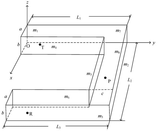
Figure 1.
U-shaped roadway model diagram.
3.1.1. Mirror Point Calculation
A three-dimensional coordinate system was established as shown in Figure 1. The coordinates of the transmitting point are T(xt, yt, zt), the receiving point is R(xr, yr, zr), the mirror point is I(xi, yi, zi), and the equation of the reflecting plane m is set as Ax + By + Cz + D = 0.
A plumb line of reflection plane m was made through emission point T, and the foot of the plumb line was F(x, y, z). I is the mirror image point of emission point T in reflection plane m, as shown in Figure 2. From the coordinates of the emitting point T and the pendant point F, the linear equation of TF is
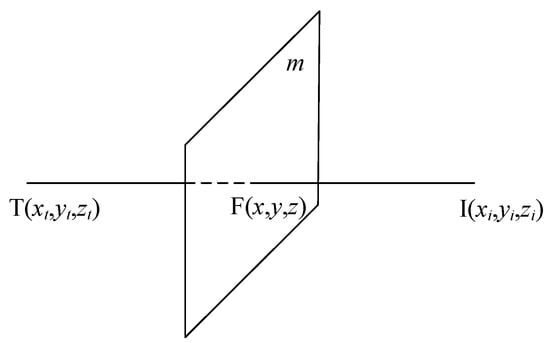
Figure 2.
Calculation of mirror points.
Because the pendant point F is the midpoint of line TI, the following relationship is satisfied:
According to the pendant point F both on the line TI and in the plane m, and using (1) and (2), the equation of plane m can be obtained:
Substituting k into (1) yields the coordinates of the pendant point F:
Finally, (4) is substituted into (2) to obtain the coordinates of the mirror point I(xi, yi, zi):
3.1.2. Mirror Point Evaluation
According to the principle of the mirror method, to determine the position of the reflection line, it is necessary to connect the mirror point with the receiving point. The point where the line intersects the reflecting surface is the reflection point, which is located on the reflecting surface. When the reflection point is valid, the mirror point is also valid. The scene applied in this study is a U-shaped roadway; therefore, when the mirror points at all levels are valid, the corresponding valid reflection lines can be obtained. There are two corners and a relay node P between the transmitting point T and receiving point R. Unlike the propagation mode of a straight roadway, the rays emitted at the transmitting point are blocked by any of the planes m4, m5, and m6, which causes them to become invalid reflection lines. This is illustrated in Figure 3.
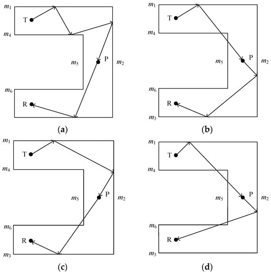
Figure 3.
Valid and invalid reflection lines. (a) Valid reflection lines; (b) invalid reflection lines over planes m4 and m5; (c) invalid reflection lines over planes m5 and m6; (d) invalid reflection lines over planes m4, m5, and m6.
For the U-shaped roadway, a valid reflection point must satisfy the following conditions:
- (a)
- The reflection point is located on the line connecting the mirror and reception points and intersects with the reflection plane (except for the boundary of the reflection plane).
- (b)
- The lines connecting the reflection point to the transmitting point, the reflection point, the relay node, and the receiving point cannot be obscured by the plane m4, the plane m5, and the plane m6.
- (c)
- When propagating in a straight roadway, the reflection point is valid if conditions a and b are satisfied.
- (d)
- The ray emitted from the emitting point needs to pass through the relay node, from which it is emitted to reach the reflecting surface, and the reflecting point is valid if condition a and condition b are satisfied.
3.1.3. Reflecting Surfaces Boundary Evaluation
For the U-shaped roadway, electromagnetic waves passing through the boundary of the reflection plane may be launched by bypassing and other phenomena. To determine whether a reflection point exists in a reflection plane, the extent of the boundary of the reflection plane must be determined. As reflection planes m7 and m8 are U-shaped, electromagnetic waves passing through the boundary of these planes are prone to bypass and other phenomena. Using reflection plane m8 as an example, we split it into rectangular planes similar to several other reflecting surfaces, planes M1, M2, and M3, and verify that the reflection point is located in the plane to determine the scope of the boundary for each rectangular plane. If the reflection point is within the range of any one of its planes, the reflection point is valid. According to the principle of the mirror image method, it is known that the mirror point is then also valid.
Figure 4 shows a two-dimensional schematic of the reflection plane m8 of the U-shaped mine roadway after it was split into three rectangular planes, M1, M2, and M3. Let the coordinates of the reflection point be H(xh, yh, zh); when point H is in the rectangular plane M1, it should satisfy 0 < xh < a and 0 ≤ yh < L1; if it is in the plane M2, it should satisfy a ≤ xh ≤ (L2—a) and (L1—c) < yh < L1; and if it is in the plane M3, it should satisfy (L2—a) < xh < L2 and 0 ≤ yh < L3. Similarly, the same method can be used for the other reflection planes. The method used for validating the boundary range of the reflection plane is consistent with this method.
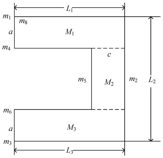
Figure 4.
Two-dimensional segmentation of the plane m8.
3.1.4. Reflection Point Calculation
The coordinates of the mirror image point were derived from Equations (1)–(5) in the previous context. When the line IR intersects any reflecting plane m with exactly one intersection point H, the point H is the reflection point, as shown in Figure 5.
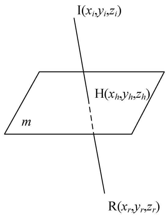
Figure 5.
Calculation of reflection point.
Knowing that the coordinates of the mirror and receiving points are I(xi, yi, zi) and R(xr, yr, zr), respectively, those of the reflecting point are H(xh, yh, zh), and because the ratios of and are the same, that is
Because the reflection point H is on both line IR and in the reflection plane m, (6) and the equation of the reflection plane show that
The coordinates of reflection point H(xh, yh, zh) can be obtained by combining (6) and (7):
3.2. Reflection Path Validity
The number of the second-time to eighth-time valid reflection lines in the U-shaped roadway can be calculated based on the determination of valid reflection paths. The following is the specific procedure for determining four-time, five-time, and six-time valid reflection paths:
3.2.1. Four-Time Valid Reflection Paths
Figure 6 shows the two-dimensional four-time valid reflection paths, where the combination of secondary reflection from point T to point P and secondary reflection from point P to point R as an example.
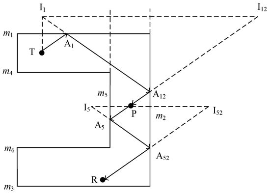
Figure 6.
Two-dimensional diagram of four-time valid reflection paths.
- (a)
- Create a primary mirror image of the emitting point T with respect to plane m1 and obtain the primary mirror point I1.
- Set point I1 as the base point, create a secondary mirror image in plane m2, and obtain a secondary mirror point I12.
- Connect point I12 with point P, and the intersection point of plane m2 is A12.
- Connect point A12 with point I1, and the intersection point of plane m1 is point A1.
- Points T, A1, and A12 are connected sequentially to form a secondary valid reflection path.
- (b)
- A primary mirror of relay node P is made with respect to plane m5 to obtain the primary mirror point I5, and a secondary mirror in plane m2 is made based on this point to obtain the secondary mirror point I52.
- Connecting point I52 with point R, the intersection point in plane m2 is A52.
- Connecting point A52 with point I5, the intersection point in plane m5 is A5.
- The connecting points P, A5, A52, and R form a secondary valid reflection path in that order.
The transmitting point T to the relay node P has six reflecting surfaces, and each surface theoretically has a primary mirror point. There are, therefore, a total of six primary mirror points, and each one has five secondary mirror points in addition to its own reflective plane. The transmitting point T to the relay node P therefore has 30 secondary mirror points, that is, 30 reflection lines. The relay node P to the receiving point R therefore also has 30 secondary mirror points, that is, 30 reflection lines. This combination, therefore, has a total of 60 points and 900 reflection lines. Similarly, for the combination where there is one reflection from the transmitting point T to the relay node P and three reflections from the relay node P to the receiving point R, and the combination where there are three reflections from the transmitting point T to the relay node P and one reflection from the relay node P to the receiving point R, there are theoretically 156 mirror points and 900 reflection lines. Therefore, all combinations of the four-time reflection paths theoretically have a total of 372 mirror points and 2700 reflection lines.
3.2.2. Five-Time Valid Reflection Paths
Figure 7 shows the two-dimensional five-time valid reflection paths, where the combination of points T to P as a secondary reflection and points P to R as a tertiary reflection are used as an example.
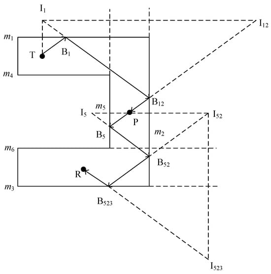
Figure 7.
Two-dimensional diagram of five-time valid reflection paths.
- (a)
- The emitting point T is first mirrored with respect to plane m1 to obtain the first mirror point I1.
- Set I1 as the base point; T is mirrored in plane m2 to obtain the second mirror point I12, which is connected to point P.
- The intersection of plane m2 is B12; point B12 is then connected to point I1, and the intersection of plane m1 is B1.
- By connecting the points T, B1, and B12 sequentially, a secondary valid reflection path was formed.
- (b)
- Mirror relay node P with respect to plane m5 for one level and obtain the first-level mirror point I5.
- Set I5 as the base point, mirror it on plane m2 for two levels, and obtain the second-level mirror point I52.
- I52 is then used as the base point, mirroring it in plane m3 for three levels and obtaining the third-level mirror point I523; connect point I523 with point R.
- The point of intersection in plane m3 is B523; connect the point B523 with to point I52.
- Finally, connect the point B52 with point I5, and the intersection in plane m5 is B5.
- Points B523 and I52 are connected to the point of intersection B52 in the plane m2.
- Finally, B52 and I5 are connected in plane m5 intersection for B5; sequentially connected points P, B5, B52, B523, and R form a tertiary valid reflection path.
From the above, it can be seen that the transmitting point T to relay node P theoretically has 30 secondary mirror points, that is, 30 reflection lines, and the relay node P to receiving point R theoretically has 150 tertiary mirror points, that is, 150 reflection lines. Therefore, there are 180 mirror points and 4500 reflection lines in this combination. Similarly, when the combination of the transmitting point T to relay node P is a tertiary reflection and the relay node P to receiving point R is a secondary reflection, there are theoretically 180 mirror points and 4500 reflection lines. For the combination where there is one reflection from the transmitting point T to the relay node P and four reflections from the relay node P to the receiving point R, and the combination where there are four reflections from the transmitting point T to the relay node P and one reflection from the relay node P to the receiving point R, there are theoretically 756 mirror points and 4500 reflection lines. Therefore, all combinations of the five-time reflection paths theoretically have a total of 1872 mirror points and 18,000 reflection lines.
3.2.3. Six-Time Valid Reflection Paths
Figure 8 shows the two-dimensional six-time valid reflection paths, where the combination of points T to P as a secondary reflection and points P to R as a quaternary reflection are used as an example.
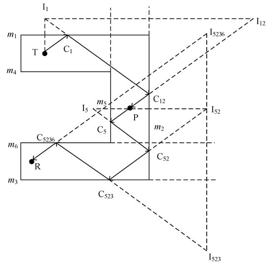
Figure 8.
Two-dimensional diagram of six-time valid reflection paths.
- (a)
- Create a primary mirror of the emission point T with respect to plane m1 to obtain the primary mirror point I1.
- Set I1 as the base point, and a secondary mirror is made in plane m2 to obtain the secondary mirror point I12.
- Connect point I12 with point P, and the intersection point of m2 in the plane is C12.
- Connect the point C12 with point I1, and the intersection point m1 in the plane is C1.
- Connect points T, C1, and C12 in turn to form a secondary valid reflection path.
- (b)
- Relay node P is mirrored with respect to plane m5 to obtain the first-level mirror point I5.
- With I5 as the base point, it is mirrored in plane m2 to obtain the second-level mirror point I52.
- With I52 as the base point, it is mirrored in plane m3 to obtain the third-level mirror point I523.
- Finally, with I523 as the base point, it is mirrored in plane m6 to obtain the fourth-level mirror point I5236.
- The I5236 point and R point connection in plane m6 intersect at C5236.
- The C5236 point and I523 point are connected to the plane m3 intersection for C523.
- The C523 point and I52 point are connected to the plane m2 intersection for C52.
- Finally, points C52 and I5 are connected to the plane m5 intersection for C5.
- Sequentially connect points P, C5, C52, C523, C5236, and R.
- Points P, C5, C52, C523, C5236, and R form a quaternary valid reflection path.
This shows that the transmitting point T to the relay node P theoretically has 30 secondary mirror points, that is, 30 reflection lines, and the relay node P to the receiving point R theoretically has 750 quadruple mirror points, that is, 750 reflection lines; therefore, there are 780 mirror points and 22,500 reflection lines in this combination. Similarly, for the combination of transmitting point T to relay node P as a quadruple reflection, and relay node P to receiving point R as a secondary reflection, there are 780 mirror points and 22,500 reflection lines. When the combination of transmitting point T to relay node P is one reflection and relay node P to receiving point R is five reflections, and when the combination of transmitting point T to relay node P is five reflections and relay node P to receiving point R is one reflection, there are theoretically 3756 mirror points and 22,500 reflection lines. For the combination of three reflections from transmitting point T to relay node P, and three reflections from relay node P to receiving point R, there are theoretically 300 mirror points and 22,500 reflection lines. Therefore, all combinations of the six-time reflection paths theoretically have a total of 9372 mirror points and 112,500 reflection lines.
4. Reflected Field Strength Calculation
To simplify the model calculations, a relay node is placed at the center of the roadway. This node is usually equipped with an amplifier that is capable of receiving weaker electromagnetic waves and amplifying them close to the original intensity through enhancement processing so that the antenna can be viewed as re-emitting electromagnetic waves at the relay node. According to the above theory, the maximum number of reflections from the relay node to the receiving point is seven.
4.1. Incidence Angle, Path Length, and Reflection Coefficient
Using the mirror image method, the incidence angle, reflection coefficient, and path length of the ray for each valid reflection are calculated, and the effective reflected field strength is calculated at the receiving point [23]. Take the reflective surfaces m2 and m3 as an example, where the ray from point P arrives at point R after one valid reflection.
Figure 9 shows that the ray emitted by the relay node P reaches the receiving point R with one reflection from the reflecting surface m2; the acute angle between the vector and the normal vector of the reflecting surface m2 is then the angle of incidence θi, i.e., the cosine value is
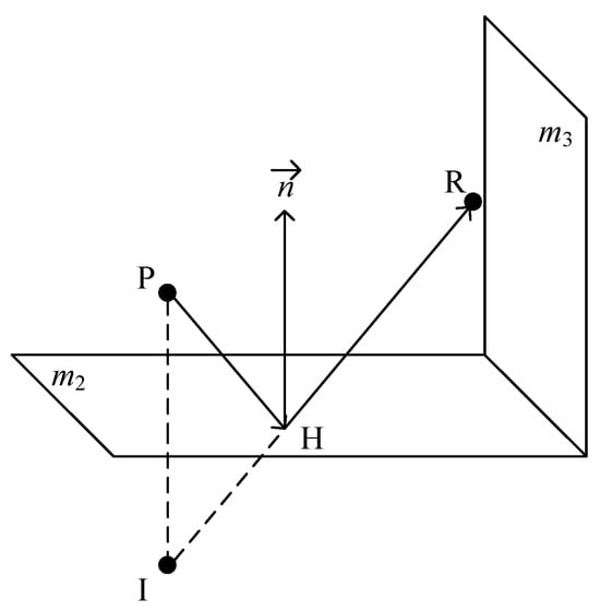
Figure 9.
Three-dimensional primary valid reflection map.
The path length of one valid reflection is the sum of the distance between the relay node P and the reflection point H, and the distance between the reflection point H and the receiving point R, which can be determined according to the formula for the distance between two points:
When a homogeneous plane wave is incident on the interface, any direction of the incident wave electric field vector should be divided into two components: one parallel and one perpendicular to the incident surface. The reflection coefficients H‖ of the horizontally polarized wave and H⊥ of the vertically polarized wave are calculated according to Fresnel’s reflection law, respectively, and their expressions are
In (12) and (13), is the relative dielectric constant of the roadway wall.
4.2. Reflected Field Strength
A half-wave dipole antenna was used as a transmitter, and its electric field is given by
In (14), d is the distance from the reflection point to the relay node, Im is the maximum current in the antenna, k is the propagation constant, and θ is the angle of incidence.
Then, the incident wave electric field vector is
According to Fresnel’s law of reflection, the reflected wave electric field vector is
In (15) and (16), α is the angle between the incident wave and the horizontally polarized wave; β is the angle between the incident wave and the vertically polarized wave; and are the unit vectors of the horizontal and vertical polarization before reflection, respectively; and are the unit vectors of the horizontal and vertical polarization after reflection, respectively; and is the vector of the incident wave, satisfying the following expressions:
For a single reflection, the field strength [24] for each primary reflection is
In (20) and (21), H1⊥ and H1‖ are the vertical and horizontal polarized wave reflection coefficients of the primary reflection, respectively; and are the unit vectors of the horizontal and vertical polarization before the primary reflection, respectively; and are the unit vectors of the horizontal and vertical polarization after one reflection, respectively; q is the distance from the relay node to the reflection point; and q′ is the distance from the reflection point to the reception point.
Thus, for p1 primary reflection lines, the resulting total field strength is
The method for calculating the reflection field strength for two- to seven-time reflection paths is consistent with that above. According to the superposition theorem [25], the field strength at the receiving point is the vector superposition of the direct field strength and the field strength vectors of the effective one to seven-time reflection lines, which is expressed as follows:
5. Simulation Analysis
The theory of the U-shaped roadway has been analyzed above by using the mirror image method, and further simulation was conducted using Python software to analyze the electromagnetic reflection propagation law of the U-shaped roadway. Let the width of the U-shaped roadway be 5 m and the height be 4 m. The lengths of the two roadways along the y-axis are both 20 m, and the length along the x-axis is 30 m.
5.1. Number of Effective Reflection Lines
Let the distance from the transmitting point to the reflecting surface m1 be w1 and the distance from the receiving point to the reflecting surface m6 be w2; let the height of the transmitting and receiving points be v1 and v2, respectively; let the distance from the receiving and transmitting points to the corner be g2, and g1, respectively.
5.1.1. Distance from Sending/Receiving Points to Corners
Figure 10 shows how the number of valid reflection lines varies with increasing distance from the launch point to the corner, where w1 = w2 = 2.5 m, v1 = v2 = 2 m, g2 = 7 m, and g1 gradually increases from 0 to 8 m.
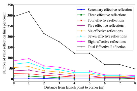
Figure 10.
Number of valid reflection lines as a function of the distance from the launch point to the corner.
The simulation results in Figure 10 show that the number of effective reflection lines for each number of times shows an overall decreasing trend. This is because the distance from the launch point to the corner increases, the initial incidence angle of the rays decreases, and most of the rays are blocked by the obstacle plane, which makes it difficult for them to reach the receiving point. When the emission point was farthest from the corner, the lowest number of valid reflection lines was available. In addition, when the receiving point was fixed, the number of valid reflection lines after many reflection times was higher than those for few reflection times (second, third, and fourth reflection times) as the distance from the transmitting point to the corner increased, which is in accordance with the theoretically deduced results.
Figure 11 shows how the number of valid reflection lines varies as the distance from the receiving point to the corner increases, where w1 = w2 = 2.5 m, v1 = v2 = 2 m, g1 = 5 m, and g2 gradually increases from 0 to 8 m.
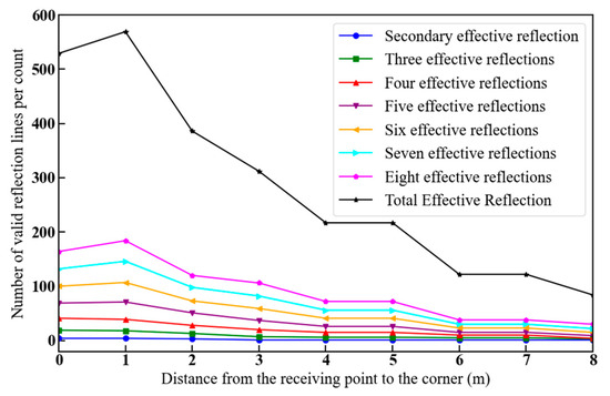
Figure 11.
Number of valid reflection lines as a function of the distance from the receiving point to the corner.
Figure 11 shows that the distance from the receiving point to the corner gradually increases, the number of valid reflection lines after many reflection times is higher than those for few reflection times, and the number of effective reflection lines for each number of times shows an overall decreasing trend, as shown in Figure 10. This is because of the symmetry of the U-shaped roadway around the relay node. When the position of the transmitting point is unchanged, as the distance from the receiving point to the corner increases, the change in the number of effective reflection lines follows the same trend as in Figure 10.
5.1.2. Sending and Receiving Points Location
Figure 12 shows how the number of valid reflection lines varies with increasing horizontal position of the launch point, where w1 gradually increases from 0 to 5 m, w2 = 2.5 m, v1 = v2 = 2 m, and g1 = g2 = 7 m.
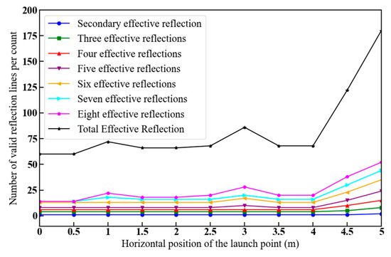
Figure 12.
Number of valid reflection lines as a function of the horizontal distance from the launch point.
As shown in Figure 12, the number of high valid reflection lines was higher than the number of low valid reflection lines as the horizontal distance from the launch point increased. In particular, the maximum number of valid reflection lines was found 5 m from the launch point to the reflecting surface m1, indicating that the reflection lines were less obstructed by the obstacle plane at that location. However, when that distance is 2.5 m, the number of valid reflection lines increases, indicating that when the horizontal position of the transmitting point w1 is 2.5 m and that of the receiving point w2 is 2.5 m, the conditions for electromagnetic wave propagation are favorable.
Figure 13 demonstrates how the number of valid reflection lines varies with increasing vertical position of the launch point, in which w1 = w2 = 2.5 m, v1 gradually increases from 0 to 4 m, v2 = 2 m, and g1 = g2 = 7 m.
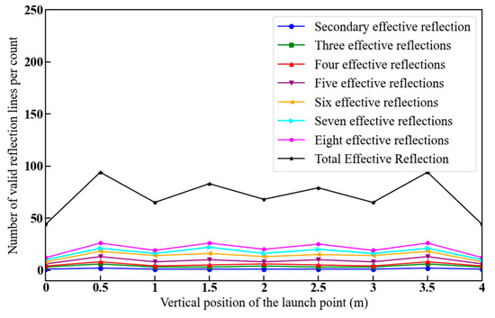
Figure 13.
Number of valid reflection lines as a function of the vertical distance of the launch point.
From Figure 13, it can be concluded that the number of valid reflection lines does not change significantly as the vertical distance from the launch point increases. The shading by the obstacle plane makes the number of high valid reflection lines higher than that of low valid reflection lines. The number of valid reflection lines is more sensitive to changes in the horizontal than the vertical position of the launch point. This is due to changes in the horizontal position changing the initial angle of incidence.
5.2. Reflected Field Strength at Receiving Point
Since the relay node divides the U-shaped roadway into two symmetrical L-shaped roadways, it is sufficient to analyze the reflection field strength between the relay node and the receiving point to derive the electromagnetic reflection propagation law in the U-shaped roadway. According to the theoretical analysis of the reflected field strength, the strength at the receiving point is affected by the position of the relay node and the receiving point in the roadway, the transmitting frequency of the antenna [26], the relative permittivity of the roadway wall, and the width of the roadway. The transmission frequency of the antenna was 2.5 GHz, and the relative dielectric constant of the roadway wall was 6.
5.2.1. Relay Node and Receiving Point Location
Figure 14 shows the variation in reflected field strength with increasing distance between the relay and receiving point when the height difference between the relay node and receiving point is 0, 1, and 1.5 m. Let the distance from the relay node to the reflection plane m5 be w3 = 2.5 m, the distance from the receiving point to the reflection plane m6 be w2 = 2.5 m, and the height of the relay node be v3 = 2 m. The receiving point starts to move along and parallel to the roadway wall 10 m above the second corner. It then passes through the second corner until it arrives at the end point 10 m away from the second corner, i.e., the distance between the relay node and the receiving point is the path passed by the receiving point length.
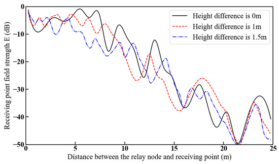
Figure 14.
Reflected field strength at the receiving point as a function of the distance between the relay node and the receiving point for different height differences.
Figure 14 shows that the overall effect of the height differences on the reflected field strength at the receiving point was small. When the relay node is at the same height as the receiving point, the reflected field strength at the receiving point is greater than when there is a height difference because the receiving point deviates from the maximum radiation direction of the relay node, resulting in a reduction in the number of valid reflection lines. When the distance between the relay node and receiving points exceeds 10m, the reflected field strength attenuation is high. This is due to the presence of corners, which reduces the number of valid reflection lines, consistent with the trend of the attenuation curves obtained in the literature [27,28] for mine roadways. At this time, the maximum attenuation of the reflection field strength is approximately 40 dB. Since the U-shaped roadway is a symmetrical structure, if the influence of electromagnetic wave at the relay node is not considered, the maximum attenuation of the reflected field strength at the receiving point is about 80 dB for the electromagnetic wave emitted by the transmitting point in the U-shaped roadway.
5.2.2. Antenna Frequency
Figure 15 shows the reflected field strength variation in the antenna transmitting frequency of 2.5, 4.5, and 5.2 GHz with the increase in the distance between the relay node and the receiving point. Let the distance from the relay node to the reflection plane m5 be w3 = 2.5 and the distance from the receiving point to the reflection plane m6 be w2 = 2.5 m; the heights of both the relay node and the receiving point are 2 m, and the receiving point is moved in the same way as in Figure 14.
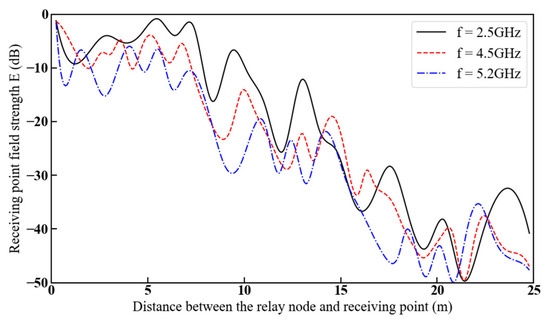
Figure 15.
Reflected field strength at the receiving point as a function of the distance between the relay node and the receiving point at different frequencies.
Figure 15 shows that the reflected field strength at the receiving point shows an overall attenuation trend as the distance between the relay node and the receiving point increases. When the distance between the relay node and receiving points exceeds 10 m, due to the presence of a corner, the attenuation of the reflected field strength at the receiving point at the frequency of 5.2 GHz is higher than that at the frequency of 2.5 and 4.5 GHz, which is consistent with the conclusion from previous studies [29].
5.2.3. Relative Permittivity of Roadway Walls
Figure 16 shows the variation in reflected field strength with increasing distance between the relay node and the receiving point for relative dielectric constants of the roadway wall of 6, 10, and 14. Let the distance from the relay node to the reflection plane m5 be w3 = 2.5 m and the distance from the receiving point to the reflection plane m6 be w2 = 2.5 m; the heights of both the relay node and the receiving point are 2 m, and the receiving point is moved in the same way as in Figure 14.
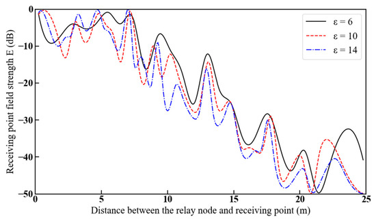
Figure 16.
Reflected field strength at the receiving point as a function of the distance between the relay node and the receiving point for different dielectric constants.
As can be seen from Figure 16, when the transmission frequency is 2.5 GHz, as the distance between the relay node and the receiving point increases, the reflected field strength at the receiving point gradually attenuates. Especially when passing through a corner, the attenuation of the reflected field strength at the receiving point accelerates. As the dielectric constant increases, the attenuation of the reflected field strength at the receiving point becomes greater. This is because an increase in the dielectric constant leads to an increase in the reflection coefficients in both the vertical and horizontal directions, thus reducing the reflected field strength at the receiving point [30].
5.2.4. Impact of Roadway Width
Figure 17 shows the variation in the reflected field strength with increasing distance between the relay node and the receiving point for roadway widths of 4, 5, and 6 m. Let the distance from the relay node to the reflection plane m5 be w3 = 2.5 m and the distance from the receiving point to the reflection plane m6 be w2 = 2.5 m; the heights of both the relay node and the receiving point are 2 m, and the receiving point moves in the same manner as shown in Figure 14.
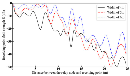
Figure 17.
Reflected field strength of the receiving point as a function of the distance between the relay node and the receiving point for different roadway widths.
From Figure 17, as the distance between the relay node and the receiving point increases, the attenuation of the reflected field strength at the receiving point becomes more significant. The presence of corners in the roadway accelerates the attenuation of the reflected field strength at the receiving point. When the height of the roadway remains constant, with the increase in the distance between the relay node and the receiving point, the smaller the width of the roadway, the greater the attenuation of the reflected field strength at the receiving point. This is because the smaller the width, the smaller the initial incident angle of the rays. As a result, the rays are more likely to be blocked by the obstacle plane, leading to a reduction in the number of effective reflected rays in each reflection, which is unfavorable to the propagation of electromagnetic waves [31].
6. Analyses of Simulation Experiments
In order to verify the above conclusions, a U-shaped roadway is designed in HFSS electromagnetic simulation software, and a half-wave dipole antenna is placed at the relay node with the specific parameters shown in Table 1.

Table 1.
Parameter list of half-wave dipole antenna.
Due to the limitation of the calculation memory, let the lengths of the two roadways along the y-axis direction in the U-shaped roadway be both 3.3 m and the length along the x-axis direction be 2.6 m; the height and width are 0.6 m, and the thickness of the roadway walls is 0.1 m, as shown in Figure 18.
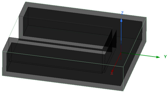
Figure 18.
Modeled U-shaped roadway with antennae.
The radiation resistance of the antenna is set to be 73.2 Ω. The specific solution parameters are shown in Table 2, and the specific steps of HFSS simulation are presented in Figure 19. From the above, it can be seen that the field strength at the receiving point is affected by the transmitting frequency of the antenna, the relative permittivity of the roadway walls, the width of the roadway, and the location between the relay node and the receiving point. The effects of these factors on the field strength will be analyzed separately below.

Table 2.
Table of simulation solution parameters for U-shaped mine roadways.
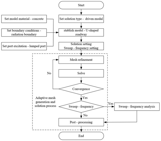
Figure 19.
Flowchart of HFSS simulation steps.
6.1. Location Analysis Between Relay Node and Receiving Point
Figure 20 shows the variation in field strength with increasing distance between the relay and receiving point when the height difference between the relay node and receiving point is 0 m, 0.1 m, and 0.2 m. The transmitting frequency of the antenna is 0.3 GHz, the relative dielectric constant of the roadway wall is 6, the distance from the relay node to the plane m5 is w3 = 0.3 m, the distance from the receiving point to the plane m6 is w2 = 0.3 m, and the height of the relay node is v3 = 0.3 m. The antenna transmits electromagnetic waves from the relay node, and the receiving point moves parallel along the roadway walls from the relay node, passing through the second corner until it stops moving at 1.7 m from the second corner., i.e., the distance between the relay node and the receiving point.
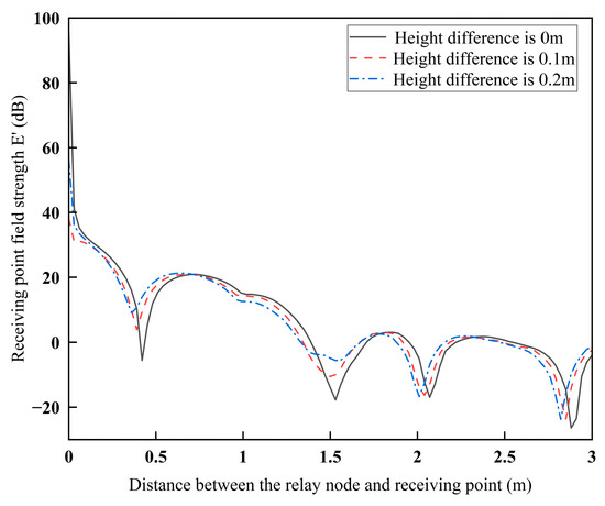
Figure 20.
Field strength at the receiving point as a function of the distance between the relay node and the receiving point for different height differences.
From Figure 20, it can be seen that the overall trend of attenuation of the field strength at the receiving point is observed with the increase in the distance between the relay node and the receiving point. When the height difference between the relay node and the receiving point increases, the attenuation of the field strength at the receiving point becomes more significant. This is because a large height difference leads to changes in the propagation path of electromagnetic waves and increases the multipath effect and propagation loss, thus reducing the field strength at the receiving point, which is consistent with the conclusion of Figure 14. Therefore, in the actual mine U-shaped roadway, the location of the sensor and the radiation source should be at different heights to increase the field strength attenuation and decrease electromagnetic interference.
6.2. Antenna Emission Frequency Analysis
Figure 21 shows the field strength variation in the antenna transmitting frequencies of 0.4 GHz, 0.45 GHz, and 0.6 GHz with increasing distance from the relay node and the receiving point, respectively. Let the relative permittivity of the roadway wall be 6. The distance from the relay node to the plane m5 is w3 = 0.3 m, the distance from the receiving point to the plane m6 is w2 = 0.3 m, the height of both the relay node and the receiving point is 0.3m, and the receiving point is moved in the same way as Figure 20.
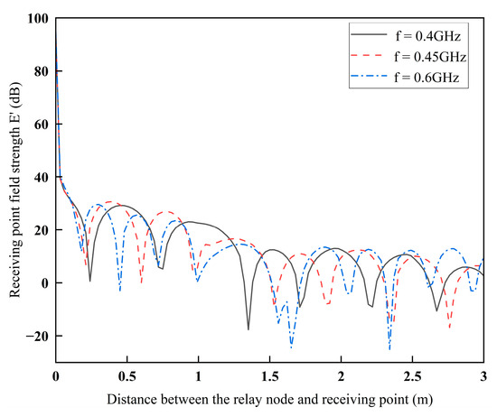
Figure 21.
Field strength at the receiving point as a function of the distance between the relay node and the receiving point at different frequencies.
From Figure 21, with the increase in the distance between the relay node and the receiving point, the field strength of the receiving point shows an overall trend of attenuation. The higher the frequency, the greater the overall attenuation of the field strength at the receiving point. The main reason is that the presence of corners makes electromagnetic waves with shorter wavelengths consume more energy when passing through. Moreover, the reflection phenomena in the roadway become more prominent, increasing the loss, which is consistent with the conclusion of Figure 15. Therefore, when sensors are placed in the U-shaped roadway, electromechanical equipment with lower frequencies should be avoided to reduce electromagnetic interference.
6.3. Analysis of the Relative Dielectric Constant of the Roadway Walls
Figure 22 shows the variation in field strength with increasing distance between the relay node and the receiving point for the relative permittivity of the roadway wall as 4, 5, and 6. Let the transmitting frequency of the antenna be 0.3 GHz. The distance from the relay node to the plane m5 is w3 = 0.3 m, the distance from the receiving point to the plane m6 is w2 = 0.3 m, the height of both the relay node and the receiving point is 0.3 m, and the receiving point is moved in the same way as in Figure 20.
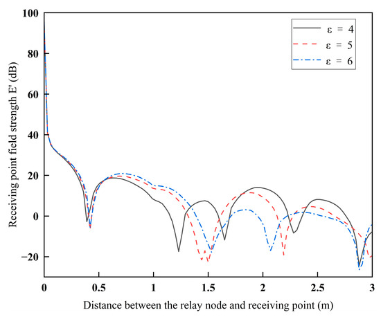
Figure 22.
Field strength at the receiving point as a function of the distance between the relay node and the receiving point for different dielectric constants.
From Figure 22, it can be seen that as the dielectric constant increases, the attenuation of the field strength at the receiving point becomes larger. This is because the larger the dielectric constant, the larger the reflection coefficient in the perpendicular direction, which makes the field strength at the receiving point smaller, in line with the conclusion of Figure 16. Therefore, the sensors should be placed in the U-shaped roadway with higher dielectric constants, which is conducive to reducing electromagnetic interference.
6.4. Roadway Width Analysis
Figure 23 shows the variation in field strength with increasing distance from the relay node and the receiving point for widths of 0.6 m, 0.7 m, and 0.8 m of the alleyway. Let the transmitting frequency of the antenna be 0.3 GHz. The relative permittivity of the roadway wall is 6, the distance from the relay node to the plane m5 is w3 = 0.3 m, the distance from the receiving point to the plane m6 is w2 = 0.3m, the heights of both the relay node and the receiving point are 0.3 m, and the moving mode of the receiving point is in line with Figure 20.
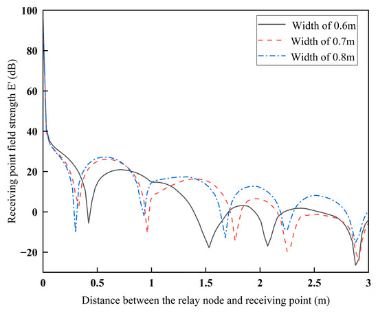
Figure 23.
Field strength of the receiving point as a function of the distance between the relay node and the receiving point for different roadway widths.
From Figure 23, as the distance between the relay node and the receiving point increases, a smaller width will lead to greater attenuation of the field strength at the receiving point. This is because wider roadways can reduce reflection losses and provide more propagation paths. Under the effect of multipath, the superposition effect of electromagnetic waves is enhanced, which is consistent with the conclusion of Figure 17. Therefore, to minimize electromagnetic interference, the sensor should be placed in a narrower U-shaped roadway to ensure accurate measurements.
7. Conclusions
For the electromagnetic reflection propagation law of a U-shaped roadway, a model based on the mirror image method was proposed, and the following conclusions were drawn.
- (1)
- The distance from the transceiver point to the corner and the position of the transceiver point in the U-shaped roadway affect the number of valid reflection lines. When the distance from the transceiver point to the corner decreased, the number of valid reflection lines increased, and the change in the vertical position had a relatively small effect on the number of valid reflection lines compared to the change in the horizontal position of the transmitting point. When the transceiver point is located in the center of the roadway, it facilitates electromagnetic wave propagation.
- (2)
- The distance and height between the relay node and the receiving point in the U-shaped roadway affected the reflected field strength at the receiving point. As the distance between the relay node and the receiving point increased, the reflected field strength of the receiving point decreased, and the attenuation of the reflected field strength at the same height was less than that at the same height when the relay node and the receiving point was not at the same height.
- (3)
- The frequency of the antenna in the U-shaped roadway, the relative dielectric constant of the roadway walls, and the roadway width all affect the reflected field strength at the receiving point. As the distance between the relay node and the receiving point increases, the reflection field strength attenuation at the receiving point will decrease with a larger roadway width, a smaller relative permittivity of the roadway walls, and a lower transmitting frequency of the antenna.
Author Contributions
Conceptualization, L.G., X.L., X.S., L.M. and C.G.; Methodology, L.G. and X.L.; Software, L.G., X.L. and X.S.; Validation, L.G., X.L., X.S., L.M. and C.G.; Formal analysis, L.G., X.L. and X.S.; Investigation, L.G. and X.L.; Resources, L.G., X.L., X.S., L.M. and C.G.; Data curation, X.L.; Writing - original draft preparation, L.G. and X.L.; Writing - review and editing, L.G., X.L., X.S., L.M. and C.G.; Visualization, L.G. and X.L.; Supervision, L.G., X.L., X.S., L.M. and C.G.; Project administration, L.G., L.M. and C.G.; Funding acquisition, L.G., L.M. and C.G. All authors have read and agreed to the published version of the manuscript.
Funding
The study was funded by the 14th Five Year National Key R&D Program Project (Project Number: 2023YFB3211001).
Institutional Review Board Statement
Not applicable.
Informed Consent Statement
Not applicable.
Data Availability Statement
Data supporting the results of this study are available from the corresponding author upon request.
Conflicts of Interest
The authors declare no conflict of interest.
References
- Jia, Q.R.; Che, D.F.; Zhong, R.Q. Component-based 3D Modeling Method for Complex Mine Roadway Network. J. Northeast. Univ. (Nat. Sci. Ed.) 2020, 41, 1774–1780. [Google Scholar]
- Liu, S.L. Simulation Analysis of Electromagnetic Wave Propagation Characteristics in Mine Roadways. Master’s Thesis, Shandong University of Science and Technology, Qindao, China, 2020. [Google Scholar]
- Yao, S.H.; Wu, X.L.; Zhang, L. Influence of Roughness of Mine Roadway Walls on Electromagnetic Wave Propagation Loss. J. Hefei Univ. Technol. Nat. Sci. Ed. 2010, 33, 4. [Google Scholar]
- Sun, J.P.; Zhang, G.M. Analysis Method of Mine Electromagnetic Wave Based on Hybrid Ray Tracing. J. China Coal Soc. 2022, 47, 2834–2843. [Google Scholar]
- Yang, R.K.; Li, Q.Q.; Yao, R.H. Multiple Scattering and Attenuation of Electromagnetic Waves in Dusty Atmosphere. Acta Phys. Sin. 2016, 65, 98–104. [Google Scholar]
- Zhang, H.L.; Xiong, T.X. Abnormal Reflection and Refraction of Electromagnetic Waves in Biaxial Left-handed Medium. J. Sichuan Norm. Univ. Nat. Sci. Ed. 2010, 2010, 4. [Google Scholar]
- Yang, S.; Liu, L.H. Study on Electromagnetic Wave Transmission Characteristics in Roadways. Laser J. 2014, 35, 2. [Google Scholar]
- Chen, N.; Cheng, L.F.; Zhang, W.J.; Jiao, X.L. Impact of Antenna Beamwidth on Electromagnetic Wave Propagation Characteristics in Roadways. Sens. Microsyst. 2022, 41, 47–50+53. [Google Scholar]
- Cheng, L.F.; Li, F.T.; Li, J. Propagation Characteristics of Electromagnetic Waves with Different Polarizations in Curved Roadways. Sens. Microsyst. 2018, 37, 14–17. [Google Scholar]
- Zhang, H.Q.; Yu, H.Z.; Wang, P.; Gao, X.J.; Ren, M.R. Establishment and Simulation of Multipath Propagation Model for Radio Waves in Rectangular Roadways. J. Wave Sci. Eng. 2008, 23, 195–200. [Google Scholar]
- Yao, S.H. Multipath Channel Model of Electromagnetic Waves in Mine Roadways Based on Mirror Method. Ind. Mine Autom. 2017, 43, 46–49. [Google Scholar]
- Mi, G.S.; Yang, W. Prediction of Electromagnetic Wave Propagation Field Strength in Semi-circular Arched Mine Roadways Based on Mirror Principle. J. China Coal Soc. 2020, 45, 1089–1099. [Google Scholar]
- Mahmoud, S.F. Modal Propagation of High Frequency Electromagnetic Waves in Straight and Curved Tunnels Within the Earth. J. Electromagn. Waves Appl. 2005, 19, 1611–1627. [Google Scholar] [CrossRef]
- Zhou, C.; Plass, T.; Jacksha, R.; Waynert, J. RF Propagation in Mines and Tunnels. IEEE Antennas Propag. Mag. 2015, 57, 88–102. [Google Scholar] [CrossRef]
- Zhou, C.; Waynert, J.; Plass, T.; Jacksha, R. Modeling RF propagation in tunnels. In Proceedings of the 2013 IEEE Antennas and Propagation Society International Symposium (APSURSI), Orlando, FL, USA, 7–13 July 2013. [Google Scholar]
- Zhou, C.; Waynert, J. The Equivalence of the Ray Tracing and Modal Methods for Modeling Radio Propagation in Lossy Rectangular Tunnels. IEEE Antennas Wirel. Propag. Lett. 2014, 13, 615–618. [Google Scholar] [CrossRef]
- Zhou, C.; Jacksha, R. Modeling and Measurement of the Influence of Antenna Transversal Location on Tunnel Propagation. In Proceedings of the 2015 IEEE International Symposium on Antennas and Propagation & USNC/URSI National Radio Science Meeting, Vancouver, BC, Canada, 19–24 July 2015. [Google Scholar]
- Zhou, C.; Waynert, J.; Plass, T.; Jacksha, R. Attenuation Constants of Radio Waves in Lossy-Walled Rectangular Waveguides. Prog. Electromagn. Res. 2013, 142, 75–105. [Google Scholar] [CrossRef]
- Fleury, B.H.; Yin, X.; Rohbrandt, K.G.; Jourdan, P.; Stucki, A. Performance of a high-resolution scheme for joint estimation of delay and bidirection dispersion in the radio channel. In Proceedings of the IEEE 55th Vehicular Technology Conference, Birmingham, AL, USA, 6–9 May 2002. [Google Scholar]
- Forooshani, A.E.; Bashir, S.; Michelson, D.G.; Noghanian, S. A Survey of Wireless Communications and Propagation Modeling in Underground Mines. IEEE Commun. Surv. Tutor. 2013, 15, 1524–1545. [Google Scholar] [CrossRef]
- Li, S.; Liu, Y.; Lin, L.; Ji, W.; Zhu, Z. Measurement, Simulation and Modeling in the Tunnel Channel with Human Bodies at 6 GHz for 5G Wireless Communication System. In Proceedings of the International Symposium on Antennas, Propagation and EM Theory, Hangzhou, China, 3–6 December 2018. [Google Scholar]
- Masson, E.; Combeau, P.; Berbineau, M.; Vauzelle, R.; Pousset, Y. Radio Wave Propagation in Arched Cross Section Tunnels–Simulations and Measurements. J. Commun. 2009, 4, 276–283. [Google Scholar] [CrossRef]
- Yu, Y. Prediction of Electromagnetic Wave Reflection Field Strength in Rectangular Curved Mine Roadways Based on Mirror Method. Master’s Thesis, Beijing Jiaotong University, Beijing, China, 2022. [Google Scholar]
- Yu, Y.; Yang, W. Prediction of Electromagnetic Wave Reflection Field Strength in L-shaped Mine Roadways Based on Mirror Method. Plateau Sci. 2021, 5, 101–114. [Google Scholar]
- Zhang, Z.B. Research on Indoor Radio Wave Propagation Prediction Based on Ray Tracing Technology. Master’s Thesis, Xidian University, Xi’an, China, 2013. [Google Scholar]
- Jacksha, R.; Zhou, C.M.; Sunderman, C. Measurement of the Influence of Antenna Pattern on Radio Frequency Propagation in a Concrete Tunnel. In Proceedings of the IEEE Radio and Wireless Symposium, Anaheim, CA, USA, 15–18 January 2018. [Google Scholar]
- Zhou, C.M.; Jacksha, R.; Reyes, M. Measurement and Modeling of Radio Propagation from a Primary Tunnel to Cross Junctions. In Proceedings of the IEEE Radio and Wireless Symposium, Austin, TX, USA, 24–27 January 2016. [Google Scholar]
- Jacksha, R.; Zhou, C. Measurement of RF Propagation around Corners in Underground Mines and Tunnels. Transactions 2016, 340, 30–37. [Google Scholar] [CrossRef][Green Version]
- Sun, J.P.; Zhang, H.W.; Zhang, L. Analysis of Electromagnetic Wave Transmission Characteristics in Rectangular Curved Roadways. Ind. Mine Autom. 2007, 2007, 4–5. [Google Scholar]
- Ranjan, A.; Misra, P.; Sahu, H.B. Experimental Measurements and Channel Modeling for Wireless Communication Networks in Underground Mine Environments. In Proceedings of the 2017 11th European Conference on Antennas and Propagation, Paris, France, 19–24 March 2017. [Google Scholar]
- Yao, S.F.; Yu, W.J. Analysis and Simulation of Wireless Channel Characteristics in Empty Mine Galleries. Min. Eng. Res. 2020, 35, 73–78. [Google Scholar]
Disclaimer/Publisher’s Note: The statements, opinions and data contained in all publications are solely those of the individual author(s) and contributor(s) and not of MDPI and/or the editor(s). MDPI and/or the editor(s) disclaim responsibility for any injury to people or property resulting from any ideas, methods, instructions or products referred to in the content. |
© 2025 by the authors. Licensee MDPI, Basel, Switzerland. This article is an open access article distributed under the terms and conditions of the Creative Commons Attribution (CC BY) license (https://creativecommons.org/licenses/by/4.0/).