Article

High Sensitivity and Wide Strain Range Flexible Strain Sensor Based on CB/CNT/PDA/TPU Conductive Fiber Membrane

School of Mechanical Engineering, Hubei University of Technology, Wuhan 430068, China
*
Author to whom correspondence should be addressed.
Appl. Sci. 2025, 15(3), 1461; https://doi.org/10.3390/app15031461
Submission received: 6 December 2024 / Revised: 17 January 2025 / Accepted: 21 January 2025 / Published: 31 January 2025

Abstract

:
Flexible strain sensors have attracted significant attention due to their critical applications in wearable devices, biological detection, and artificial intelligence. However, achieving both a wide strain range and high sensitivity remains a major challenge in current research. This study aims to develop a novel composite material with a synergistic conductive network to construct high-performance flexible strain sensors. Thermoplastic polyurethane (TPU) nanofiber membranes were first prepared using electrospinning technology, and their surface was modified with polydopamine (PDA) via in-situ polymerization, which significantly enhanced the fibers’ adsorption capacity for conductive materials. Subsequently, carbon nanotubes (CNTs) and carbon black (CB) were coated onto the PDA-modified TPU fibers through ultrasonic anchoring, forming a CB/CNT/PDA/TPU composite with a synergistic conductive network. The results demonstrated that the flexible strain sensor fabricated from this composite material (with a CB-to-CNT mass ratio of 7:3) achieved ultrahigh sensitivity (gauge factor, GF, up to 1063) over a wide strain range (up to 300%), along with a low detection limit (1% strain), fast response and recovery times (137 ms), and exceptional stability and durability. Further evaluations confirmed that this sensor reliably captured biological signals from various joint movements, highlighting its broad application potential in human motion monitoring, human–machine interaction, and soft robotics.

1. Introduction

In recent years, flexible strain sensors have gained significant attention due to their extensive applications in health monitoring [1], soft robotics [2], human–machine interaction, and biomedical engineering [3,4]. These sensors are categorized into various types based on their working mechanisms, including resistive, piezoelectric, triboelectric, and capacitive sensors [5,6,7,8]. Among them, flexible resistive strain sensors, which convert mechanical deformation into resistance signals, stand out for their high sensitivity, wide working range, and ease of signal acquisition. However, achieving a balance between high sensitivity, wide strain range, and long-term stability remains a major challenge in their development, making the design of sensors that integrate these properties a critical focus in the field.
Flexible resistive strain sensors typically consist of a flexible substrate and conductive materials [9]. The substrate primarily determines the application scenarios, while the conductive materials directly influence the sensors’ electrical performance. Compared with traditional polymer substrates, electrospun fiber membranes have garnered increased attention due to their high specific surface area, excellent mechanical flexibility, and high porosity [10]. Among these, thermoplastic polyurethane (TPU) has emerged as an ideal candidate for flexible substrates owing to its superior tensile properties, excellent elastic strain recovery, abrasion resistance, temperature tolerance, and ease of fiber formation [11]. For instance, Wang et al. fabricated a flexible sensor by modifying TPU fiber membranes with polydopamine (PDA) and incorporating silver nanoparticles (AgNPs) through hot embossing technology, achieving a wide detection range and excellent stability [12].
Despite the promising performance of single conductive networks, achieving both high sensitivity and a wide strain range remains challenging. Recently, constructing synergistic conductive networks by integrating two or more conductive materials into the flexible substrate has proven to be an effective strategy to address this limitation. Studies have demonstrated that the synergistic interaction between different conductive materials can deliver superior performance that single conductive networks cannot achieve [13,14]. For example, Mojtaba Haghgoo et al. used Monte Carlo simulations and percolation models to reveal the significant influence of synergy between carbon nanotubes (CNTs) and carbon black (CB) on strain sensor performance [15]. Tian et al. fabricated a three-dimensional synergistic conductive network using electrospun TPU fiber membranes, multi-walled carbon nanotubes (C-MWCNTs), and PEDOT, achieving high sensitivity, a wide strain range, and exceptional durability [16]. Additionally, Wang et al. developed a flexible strain sensor combining MXene, CNTs, and TPU, which exhibited a wide detection range (0–450%), ultra-low detection limit (0.05%), and high sensitivity. These studies emphasize the critical role of synergistic conductive network designs in enhancing the performance of flexible strain sensors [17].
However, the trade-off between high sensitivity and a wide strain range remains a significant challenge in sensor design. For instance, PDMS-based flexible strain sensors with Au/Ti microcracks exhibit high sensitivity (~5000) within a narrow strain range (<1%), but their strain range is limited [18]. Similarly, sensors based on CB and wrinkled Ecoflex composites achieve a strain range of up to 500%, but their sensitivity is only 67.7 [19]. Additionally, layered composites composed of reduced graphene oxide (rGO), silk fibroin (SF), and cellulose nanocrystals (CNC) demonstrate high sensitivity in small strain ranges and are suitable for arterial pulse detection, but their performance under large strain conditions is restricted [20]. Therefore, achieving an optimal balance between high sensitivity and a wide strain range remains a critical challenge in the field of flexible strain sensors [21,22,23,24,25,26].
Against this backdrop, this study employs electrospinning technology to fabricate TPU nanofiber membranes, enhancing their adsorption capacity and stability for conductive materials through PDA modification. Subsequently, CNTs and CB are deposited onto the surface of PDA-modified TPU fiber membranes via ultrasonic deposition, constructing a flexible strain sensor with a three-dimensional fiber network structure and a synergistic conductive network (CB/CNT/PDA/TPU). In this design, CNTs provide a wide strain range, CB ensures high sensitivity, and PDA significantly improves the sensor’s long-term stability. The flexible strain sensor developed in this study demonstrates excellent performance in terms of sensitivity, strain range, stability, and detection limit, excelling particularly in detecting large deformations and small vibrations. These findings highlight its potential applications in human–machine interaction and soft robotics.

2. Materials and Methods

2.1. Materials

TPU (Elastollan 1195A) was supplied by BASF GmbH, Rhineland-Palatinate, Germany. The solvent N,N-dimethylformamide (DMF) was sourced from Guangdong Zhongli Chemical Co., Ltd. (Guangzhou, China), while tetrahydrofuran (THF) was obtained from Shanghai Aladdin Biochemical Technology Co., Ltd. (Shanghai, China). Tris (tris(hydroxymethyl)aminomethane) and dopamine hydrochloride (DA·HCl) were provided by Shanghai McLean Biochemical Co., Ltd. (Shanghai, China). Carbon nanotubes (CNTs), used as conductive materials, were supplied by Shenzhen Suiheng Technology Co., Ltd. (Shenzhen, China) and carbon black (CB) was sourced from Guangdong Zhuguang New Energy Technology Co., Ltd. (Guangzhou, China).

2.2. Preparation of TPU Nanofiber Membrane

A specified amount of TPU pellets was dissolved in a DMF/THF mixed solution (mass ratio of DMF to THF = 1:1) and magnetically stirred at 60 °C for 8 h to produce a uniform TPU solution with a TPU mass concentration of 18 wt%. The resulting solution was loaded into a 10 mL syringe for subsequent electrospinning. The electrospinning parameters were as follows: the distance between the metal needle nozzle and the rotating drum collector was 15 cm, the applied voltage was 15 kV, the syringe feed rate was 1 mL/h, the drum rotation speed was 200 rpm, and the ambient temperature and humidity were maintained at approximately 25 °C and 40%, respectively.

2.3. PDA-Modified TPU Nanofiber Membrane

First, 420 mg of dopamine hydrochloride (DA·HCl) and 1.5 g of tris(hydroxymethyl)aminomethane (Tris) were dissolved in 300 mL of deionized water to prepare a DA/Tris buffer solution with a pH of 8. Next, the TPU fiber membrane obtained through electrospinning was immersed in the buffer solution and stirred at room temperature for 12 h to produce a PDA/TPU fiber membrane. After the reaction, the PDA/TPU fiber membrane was thoroughly washed multiple times with deionized water to remove any residual DA/Tris buffer solution, ensuring its purity.

2.4. Preparation of CB/CNT/PDA/TPU Flexible Strain Sensor

First, carbon black (CB) and carbon nanotubes (CNT) were added to 100 mL of ethanol and 100 mL of deionized water, and the mixture was sonicated for 30 min to obtain a uniform CB/CNT suspension. Both the TPU fiber membrane and the PDA/TPU fiber membrane were then immersed in the CB/CNT suspension and subjected to ultrasound-assisted adsorption for 2 h. During this process, the color of the fiber membrane changed to black, indicating the successful anchoring of CB and CNT onto the fibers. This ultrasound-assisted adsorption step ensures the even distribution of conductive materials onto the fibers, significantly enhancing the sensor’s sensing performance. Finally, the fiber membranes were washed several times with deionized water and air dried in a fume hood to obtain the CB/CNT/TPU fiber membrane and CB/CNT/PDA/TPU fiber membrane. The concentration of the suspension was 8 mg/mL, and different CB/CNT/PDA/TPU conductive fiber membranes were prepared by varying the mass ratio of CB to CNT. The mass ratios of CB to CNT used were 1:9, 3:7, 5:5, 7:3, and 9:1.

2.5. Characteristics

The surface morphology and microstructure of the TPU, PDA/TPU, CB/CNT/TPU, and CB/CNT/PDA/TPU nanofiber membranes were observed using a Scanning Electron Microscope (SEM). The structural properties of these membranes were analyzed using a Raman spectrometer. The material composition was characterized by Fourier Transform Infrared Spectroscopy (FTIR) in the range of 500–4000 cm−1, with a resolution of 4 cm−1. Thermogravimetric analysis (TGA) was performed under a nitrogen atmosphere, with a heating rate of 20 °C/min, raising the temperature from room temperature to 800 °C. Tensile testing was carried out using a tensile testing machine to evaluate the mechanical properties of the nanofiber membranes under uniaxial tensile force. The sample size was 40 mm × 10 mm, and each sample was tested five times under the same conditions, with the average value taken. The resistance signal of the flexible strain sensor was recorded using an LCR tester, and the strain sensing performance of the sensor was tested using the tensile testing machine in combination with the testing equipment. To ensure the accuracy of the experimental setup, aluminum film electrodes were placed at both ends of the composite nanofiber membrane.

3. Results

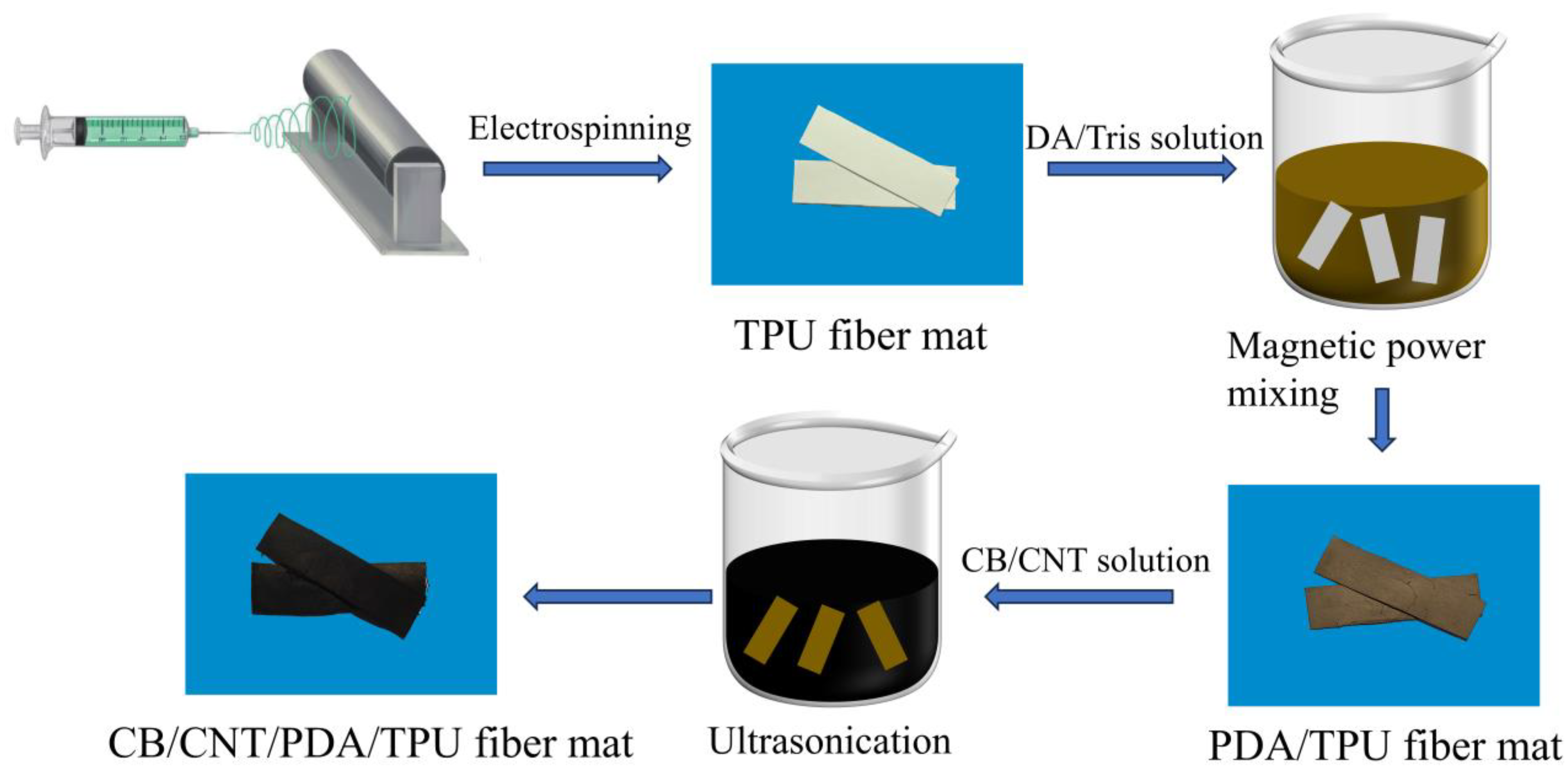
3.1. Fabrication of CB/CNT/PDA/TPU Flexible Strain Sensors

As shown in Figure 1, the fabrication process of the CB/CNT/PDA/TPU flexible strain sensor involves electrospinning, magnetic stirring, and ultrasonic treatment. First, a TPU fiber membrane is prepared via electrospinning. The TPU fiber membrane is then immersed in a DA/Tris buffer solution to deposit a PDA layer on the surface, enhancing the adhesion of the TPU fibers. During this step, the color of the fiber membrane changes from white to brown. Finally, the PDA/TPU fiber membrane is immersed in a CB/CNT mixed solution. After ultrasonic treatment, the membrane’s color transitions from brown to black, resulting in the final CB/CNT/PDA/TPU strain sensor.

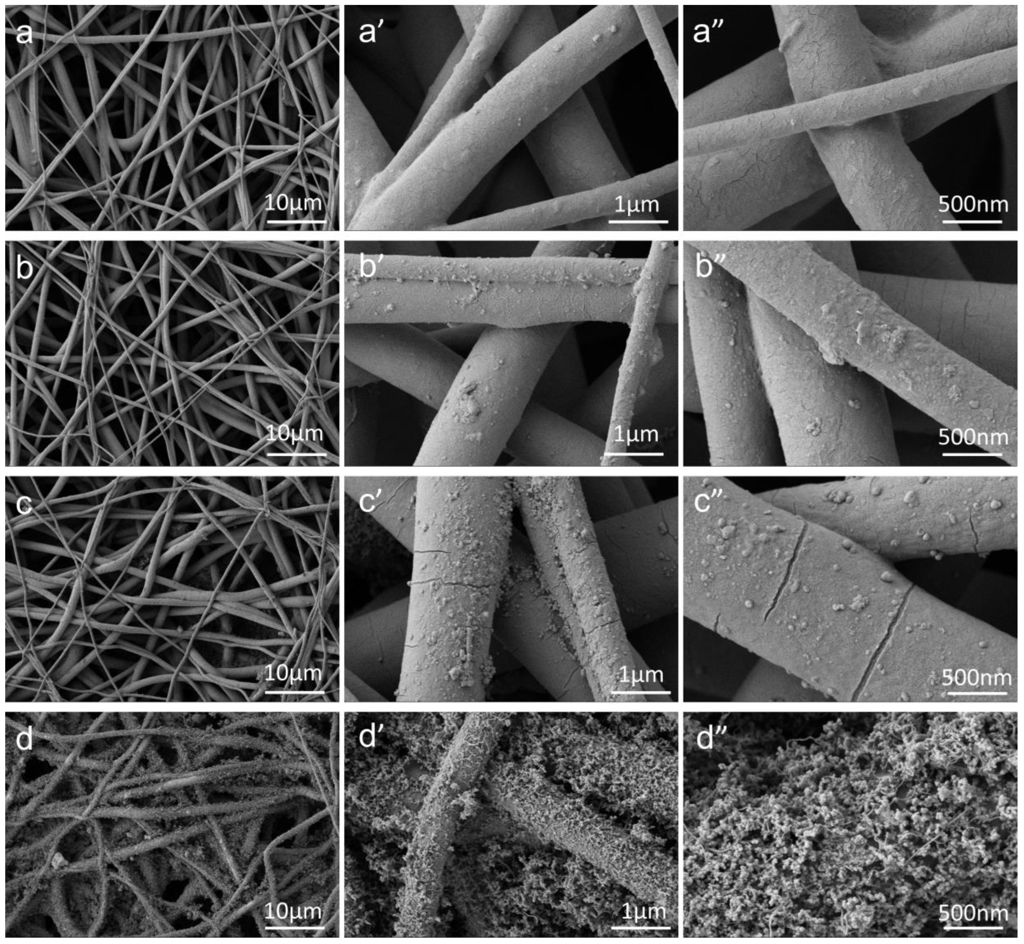
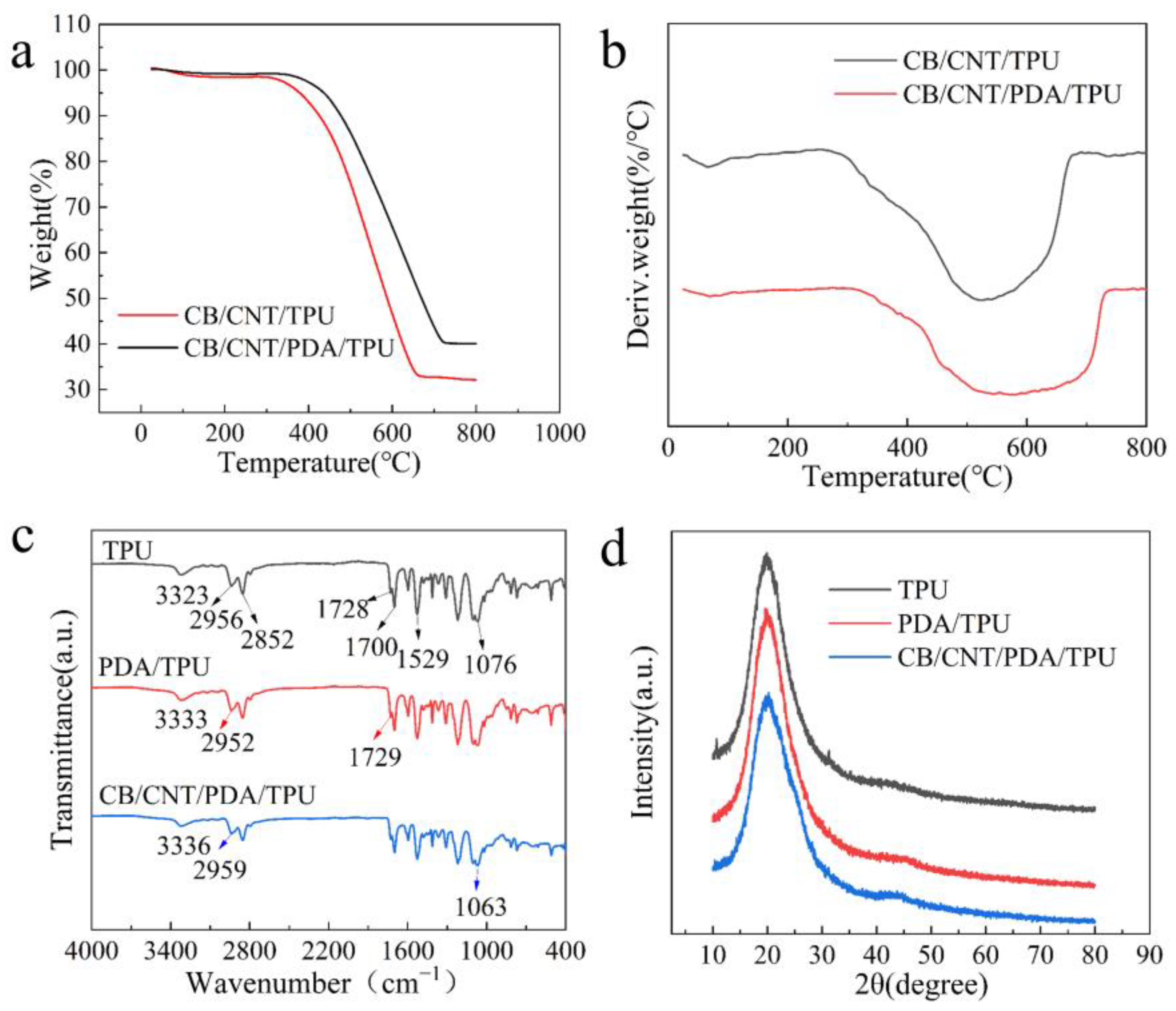
3.2. Morphology and Structure of the Fiber Membrane

Figure 2 shows the surface morphology of TPU fiber membranes, PDA/TPU fiber membranes, CB/CNT/TPU fiber membranes, and CB/CNT/PDA/TPU fiber membrane samples. As shown in Figure 2a–a”, the TPU fibers have smooth surfaces and are randomly distributed. The fibers’ internal structure contains numerous pores and nodes of varying sizes, forming a typical three-dimensional network framework, which provides abundant attachment sites for CB and CNT. In Figure 2b–b”, a dense PDA layer is formed on the fiber surfaces through in-situ polymerization. After modification with PDA, the TPU fiber surfaces become rougher. The adhesive properties of the PDA layer significantly enhance the interfacial bonding strength between CB, CNT, and TPU fibers. As shown in Figure 2c–c”, CB and CNT are successfully deposited on the TPU fiber surfaces after ultrasonic treatment. During the ultrasonic process, CB and CNT are propelled toward the nanofiber surfaces, where they undergo interfacial collisions. At the same time, portions of the nanofibers soften or melt, allowing CB and CNT to anchor onto the fiber surfaces and form a three-dimensional conductive network using the nanofibers as a scaffold. As shown in Figure 2d–d”, the PDA-modified TPU fibers show greater CB and CNT deposition compared to the pure TPU fibers in Figure 2c–c” after ultrasonic treatment. As seen in Figure 2d”, the high aspect ratio of CNT enables it to interconnect with the zero-dimensional CB aggregates, forming a synergistic CB/CNT conductive network, which significantly enhances the conductivity performance of the sensor.
The thermal stability of CB/CNT/TPU and CB/CNT/PDA/TPU samples was tested using thermogravimetric analysis (TGA). Figure 3a shows the TG curves of CB/CNT/TPU and CB/CNT/PDA/TPU nanofiber membranes. From Figure 3a, it can be observed that at a heating temperature of 800 °C, the mass loss of CB/CNT/TPU reaches 67.87%, while that of CB/CNT/PDA/TPU is 59.89%. For TPU and PDA/TPU, the mass loss at 800 °C is 90.41%. Therefore, the CB/CNT contents on CB/CNT/TPU and CB/CNT/PDA/TPU nanofibers are calculated to be 22.54% and 30.52%, respectively. This indicates that PDA modification enhances the adhesion of conductive materials on the TPU fiber surface, resulting in more CB and CNT coating. The results are consistent with Wang et al.’s findings, where increasing the CNT suspension concentration from 0.2 g/L to 1.0 g/L demonstrated that PDA/TPU exhibited a stronger capacity to bind conductive materials compared to pure TPU [27]. The thermal decomposition temperature of CB/CNT/PDA/TPU is 449.2 °C, slightly higher than the 427.7 °C observed for CB/CNT/TPU. Additionally, as shown in Figure 3b, the maximum weight loss rate of CB/CNT/PDA/TPU occurs at 571.3 °C, compared to 538.6 °C for CB/CNT/TPU. These results demonstrate that the thermal stability of the CB/CNT/PDA/TPU nanofiber membrane is significantly improved.
Fourier Transform Infrared Spectroscopy (FTIR) was used to characterize the functional groups and intermolecular interactions between the phases in TPU nanofibers and their composites. Figure 3c shows the infrared spectra of TPU, PDA/TPU, and CB/CNT/PDA/TPU samples. Due to the polymer composition and structure of TPU nanofibers, the stretching and bending vibrations of polyurethane’s N-H and -CH groups produce peaks at 3323 cm−1, 2956 cm−1, and 2852 cm−1, respectively. The peak at 1076 cm−1 corresponds to the C-O-C bond, while the peaks at 1728 cm−1, 1700 cm−1, and 1529 cm−1 are associated with the -H-N-COO- group. For PDA/TPU, the -NH absorption peak shifts from 3323 cm−1 to 3333 cm−1, the -CH absorption peak shifts from 2956 cm−1 to 2952 cm−1, and the -H-N-COO- group absorption peak shifts from 1728 cm−1 to 1729 cm−1. The peak positions of TPU and PDA/TPU are consistent with the infrared spectra reported by Wang et al., indicating that the samples were not contaminated [12]. For CB/CNT/PDA/TPU, the absorption peaks at 3323 cm−1, 2956 cm−1, and 1076 cm−1 in the TPU sample shift to 3336 cm−1, 2959 cm−1, and 1063 cm−1, respectively. The shift in peak positions reflects the interaction between TPU nanofibers and PDA, CB/CNT, demonstrating that PDA and CB/CNT have been successfully deposited onto the TPU nanofiber membranes.
X-ray diffraction (XRD) was used to investigate the crystal structure of TPU and its composites. Figure 3d presents the XRD results of TPU, PDA/TPU, and CB/CNT/PDA/TPU. For TPU, a broad diffraction peak is observed at approximately 2θ = 20°, which is attributed to the short-range ordered structure of the hard and soft domains in TPU, as well as the presence of an amorphous disordered structure. For PDA/TPU, the characteristic diffraction peak of TPU around 2θ = 20° remains unchanged, indicating that PDA modification does not affect the crystalline phase of TPU. For CB/CNT/PDA/TPU, when CB/CNT is introduced into PDA/TPU, the intensity of the diffraction peak decreases, and the peak becomes broader. The absence of sharp peaks corresponding to CB/CNT indicates that CB/CNT is well anchored on the surface of the TPU electrospun fiber membrane.

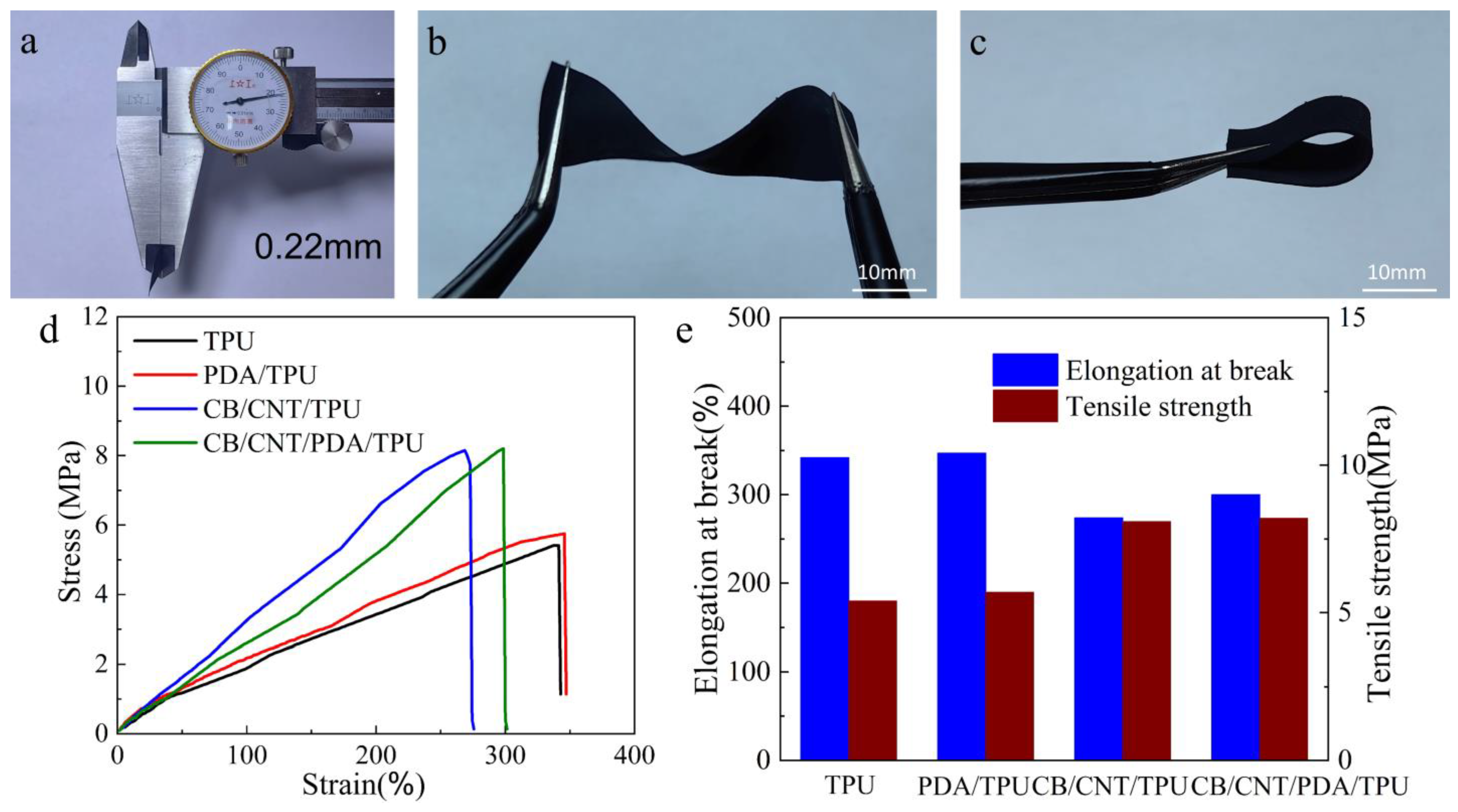
3.3. Mechanical Properties

The mechanical properties of CB/CNT/PDA/TPU were tested through uniaxial tensile testing, and compared with the mechanical properties of TPU, PDA/TPU, and CB/CNT/TPU. Each sample was tested five times under the same conditions, and the average value was taken. As shown in Figure 4a, the thickness of the CB/CNT/PDA/TPU nanofiber membrane is relatively thin, approximately 220 μm. Figure 4b,c highlight the excellent flexibility and bendability of the CCPT nanofiber membrane, demonstrating superior mechanical performance. Uniaxial tensile tests were performed on TPU, PDA/TPU, CB/CNT/TPU, and CB/CNT/PDA/TPU nanofiber membranes. Figure 4d,e present the stress–strain curves along with bar charts for elongation at break and tensile strength. The tensile strengths of TPU and PDA/TPU nanofiber membranes were measured to be 5.4 MPa and 5.7 MPa, respectively. For CB/CNT/TPU and CB/CNT/PDA/TPU nanofiber membranes, the tensile strengths increased significantly to 8.1 MPa and 8.2 MPa, representing an improvement of 50% and 44%, respectively, compared to TPU and PDA/TPU nanofiber membranes. The improved tensile strength is attributed to the excellent mechanical properties of CB and CNT. Upon introducing CB and CNT, they are uniformly dispersed within the TPU fiber membrane, and the CB + CNTs reinforcement phase structure serves as a support, effectively distributing the stress borne by the matrix. The elongation at break for TPU and PDA/TPU nanofiber membranes was 342% and 347%, respectively. This improvement can be attributed to the enhanced interfacial interactions resulting from the PDA layer coating the TPU fibers, which in turn improves their tensile performance. In contrast, the elongation at break for CB/CNT/TPU and CB/CNT/PDA/TPU nanofiber membranes was 275% and 300%, respectively, showing reductions of 67% and 47% compared to TPU and PDA/TPU. This decrease is due to the entanglement and aggregation of the conductive materials, CB and CNT, which limit the deformation capability and reduce the elongation at break. However, CB/CNT/PDA/TPU nanofiber membranes exhibited better elongation at break and tensile performance compared to CB/CNT/TPU membranes, demonstrating the enhanced mechanical properties provided by the PDA modification.

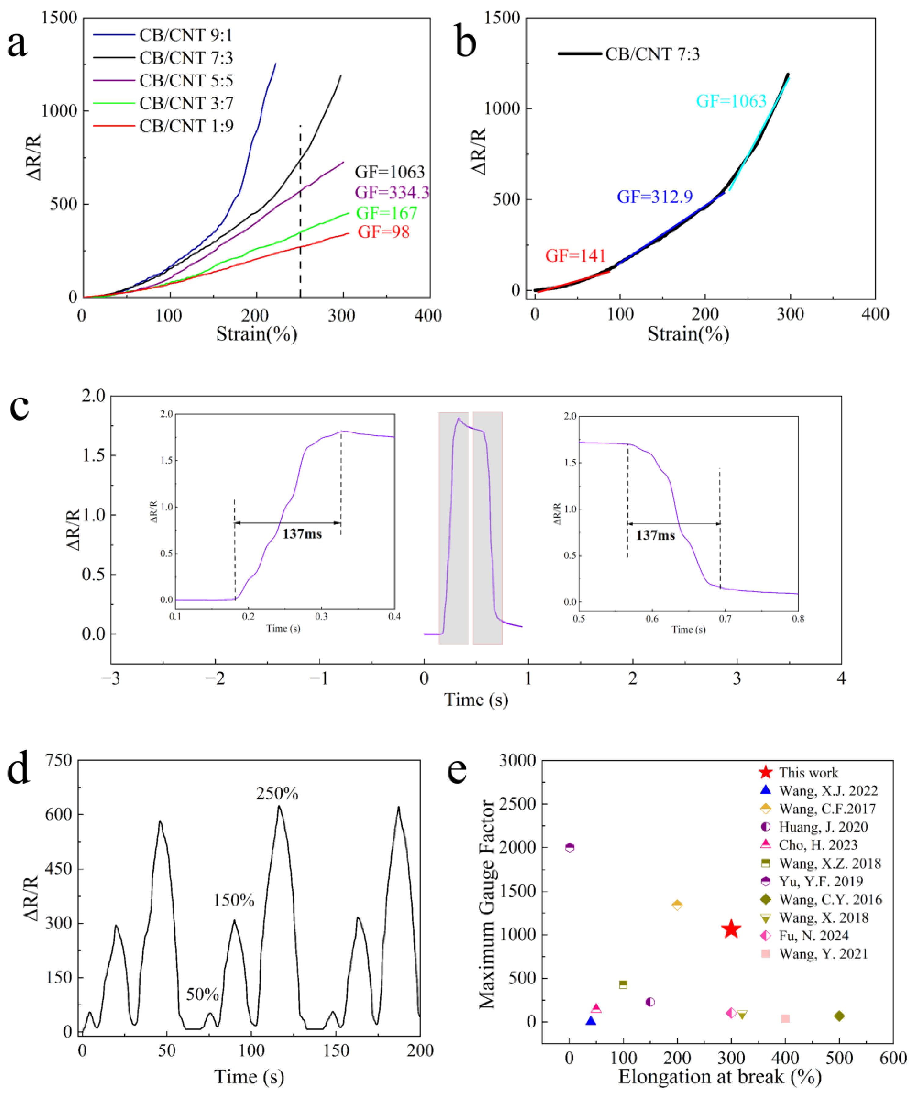
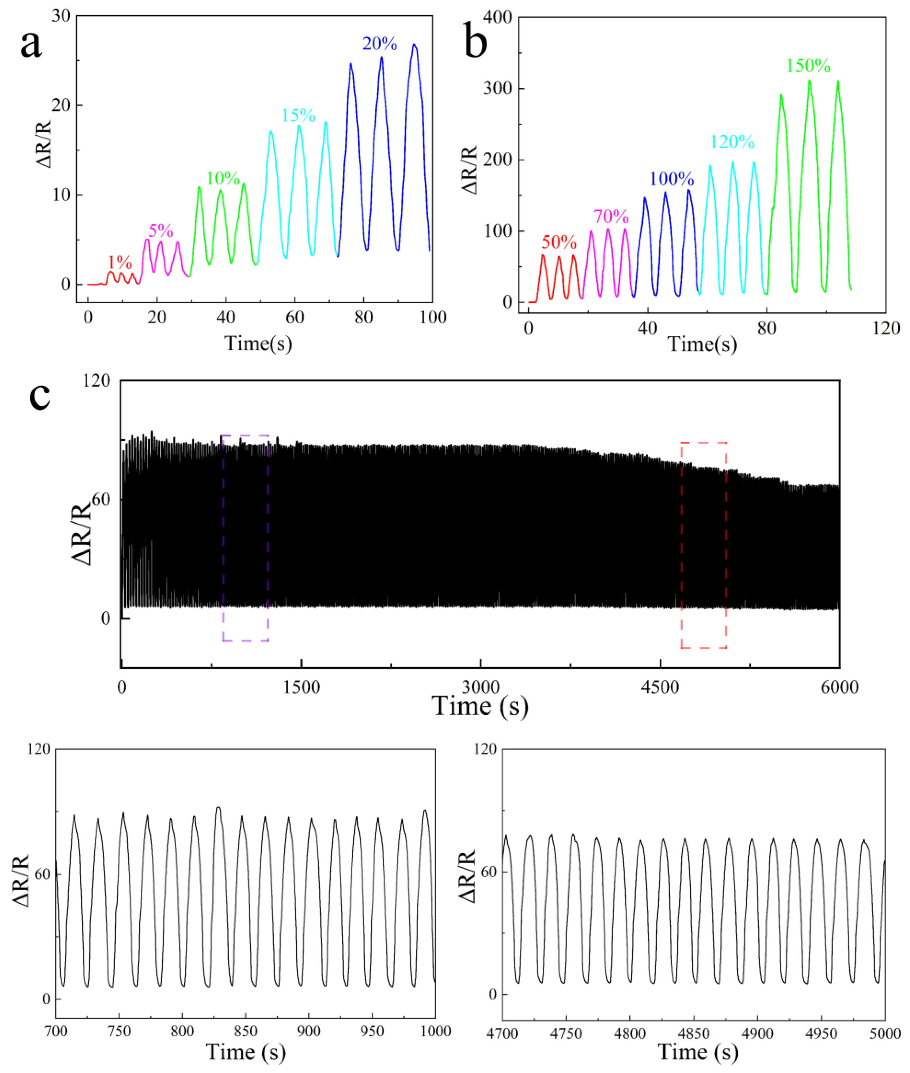
3.4. Electrical Properties

To investigate the effect of the mass ratio of CB and CNT in the conductive filler on the sensing performance, nanofiber membranes with different CB/CNT ratios were fabricated. As shown in Figure 5a, under the same strain, the slope of the curve becomes steeper with an increasing CB content, while it becomes gentler as the CNT content increases. This is because zero-dimensional CB particles tend to aggregate, while CNTs with a high aspect ratio are more likely to entangle with each other. As a result, under the same strain, nanofiber membranes with higher CB content exhibit greater relative resistance changes compared to those with higher CNT content, leading to higher sensitivity. When the CB/CNT ratio is 9:1, the tensile properties of the nanofiber membrane decrease, and the working range of the flexible sensor becomes smaller. At a strain of 250%, the gauge factors (GF) for CB/CNT ratios of 7:3, 5:5, 3:7, and 1:9 were 1063, 334.3, 167, and 98, respectively, indicating that the sensor sensitivity can be controlled by adjusting the mass ratio of CB/CNT in the conductive filler. Among these, the nanofiber membrane with a CB/CNT ratio of 7:3 better meets the comprehensive performance requirements of high sensitivity and a wide strain range. As shown in Figure 5b, the strain sensitivity of the CB/CNT 7:3 nanofiber membrane increases with increasing strain. The strain sensitivity curve for the flexible strain sensor was divided into three stages (0–100%, 100–220%, 220–300%) through linear fitting. In the strain range of 0–100%, the GF is 141; in the range of 100–220%, the GF is 312.9; and in the range of 220–300%, the GF reaches 1063. As strain is applied to the nanofiber membrane, the distance between the mixed conductive fillers increases. Larger strains cause more significant damage to the conductive network, leading to a larger GF value. Figure 5e shows that the CB/CNT/PDA/TPU strain sensor exhibits a fast strain response, with response and recovery times around 137 ms. In Figure 5d, it is evident that most of the flexible strain sensors reported in the literature do not simultaneously achieve a wide detection range and high sensitivity. However, the CB/CNT/PDA/TPU flexible strain sensor fabricated in this study offers both a wide detection range (0–300%) and high sensitivity (GF = 1063).
To verify the stability and long-term durability of the flexible strain sensor, the sensing performance of the CB/CNT (7:3) flexible strain sensor under different strain conditions was tested. As shown in Figure 5c, the sensor’s performance was evaluated under stepwise cyclic stretching at strains of 50%, 150%, and 250%. The experimental results indicate that during stepwise cyclic stretching, the change in ΔR/R follows the cyclical strain variations, showing excellent repeatability and stability. Figure 6a,b demonstrate that the CB/CNT/PDA/TPU flexible strain sensor exhibits reproducible and stable cyclic strain sensing behavior at different strains. It can accurately detect stable response signals even at a small strain of 1%, indicating that the CB/CNT/PDA/TPU flexible strain sensor has an ultra-low detection limit. From 1% small strain to 150% large strain, the CB/CNT/PDA/TPU flexible strain sensor can detect periodic signals, making it suitable for detecting human body movements in various scenarios. In practical applications, the cyclic stability and durability of the sensor are crucial factors for maintaining mechanical integrity and sensing functionality over long-term use. As shown in Figure 6c, the CB/CNT/PDA/TPU strain sensor underwent durability testing through cyclic stretching at a strain of 70%. During both the early and later stages of the cyclic tests, no significant signal fluctuations were observed, and the relative change in resistance remained stable. This indicates that the CB/CNT/PDA/TPU flexible strain sensor possesses excellent stability and durability, making it suitable for long-term applications.

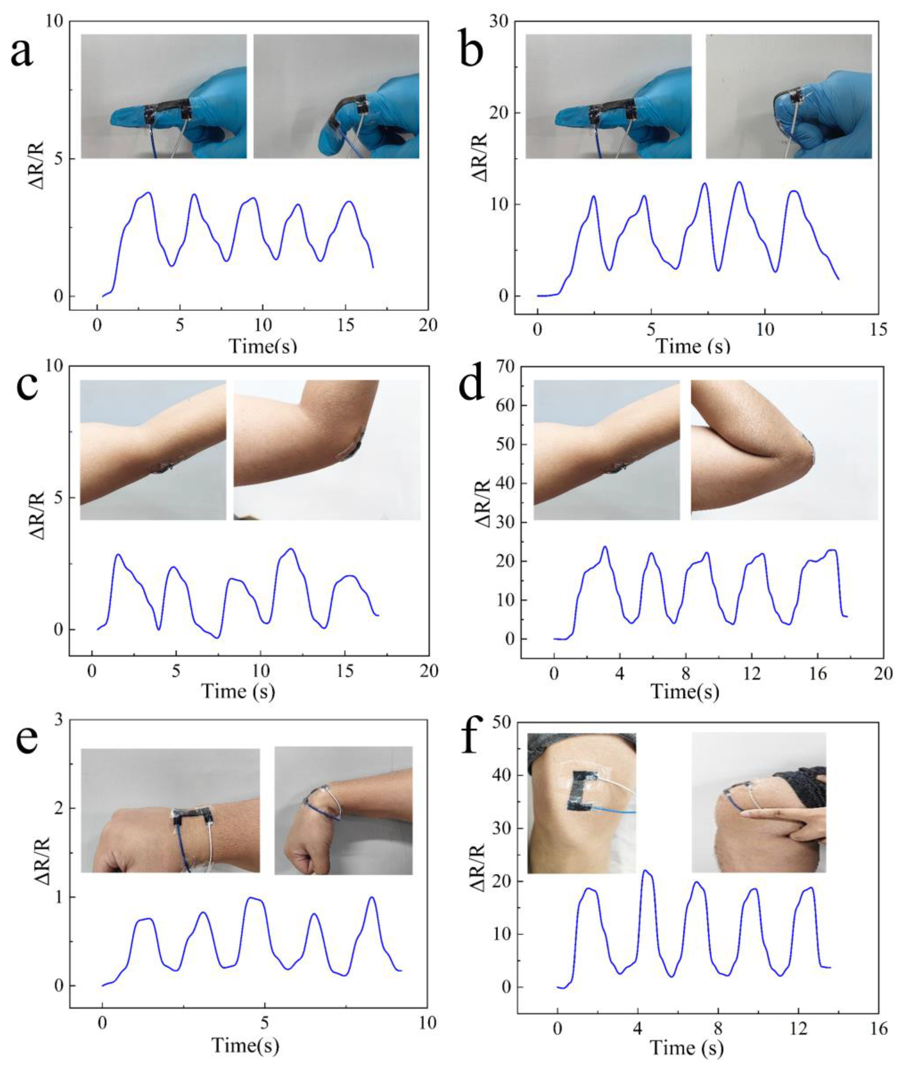
3.5. Monitoring Human Behavior

The CB/CNT/PDA/TPU flexible strain sensor, when adhered to different parts of the human body, can serve as a wearable device for monitoring human motion. Each sample was tested five times under the same conditions, and the average value was taken. As shown in Figure 7a,b, when the flexible strain sensor is applied to the index finger, the resistance change correlates with the finger’s movement during flexion. The sensor produced stable and repeatable response signals, with the resistance change when the finger was fully bent being significantly higher than in the semi-bent state. Specifically, when fully bent, the ΔR/R value was 12.5, while in the semi-bent state, it was 3.6. Similarly, Figure 7c,d show the sensor’s response to various bending states of the elbow, where the resistance change was proportional to the degree of elbow flexion. For the elbow in the semi-bent position, the ΔR/R value was 2.9, and in the fully bent position, it was 21.1. These results demonstrate that the flexible strain sensor generates varying resistance signals of different intensities, depending on the type of motion, highlighting its ability to distinguish between different movements. Figure 7e illustrates the wrist’s swinging motion, which also results in a change in resistance, showcasing the sensor’s capability to monitor subtle human movements. Figure 7f shows the extension and bending of the knee, indicating that the sensor can also monitor larger-scale human movements. These experiments confirm that the CB/CNT/PDA/TPU sensor is well suited for detecting a wide range of human body movements, from fine gestures to more substantial motions, making it an effective tool for wearable health and motion monitoring applications.

4. Conclusions

This study demonstrates the successful development of a CB/CNT/PDA/TPU (CCPT) flexible strain sensor featuring a synergistic conductive network. Through the integration of electrospun TPU nanofibers, in-situ polymerized PDA, and a CB/CNT composite, the sensor achieves an optimal balance between high sensitivity, wide strain range, and excellent durability. Specifically, the CCPT sensor (CB/CNT mass ratio of 7:3) delivers outstanding performance, including high sensitivity (GF = 1063 for strains above 220%), a wide strain range (up to 300%), rapid response and recovery times (~137 ms), and excellent stability under repeated loading and unloading cycles.
The versatile CCPT sensor is highly promising for practical applications in electronics and bioengineering. For instance, it can be utilized in electronic devices for real-time monitoring of large-scale deformations, such as those in wearable soft robotics or flexible displays. In the field of bioengineering, the sensor demonstrates potential as a reliable tool for health monitoring, including tracking subtle physiological signals like pulse waves or respiratory patterns. Additionally, it shows promise for integration into prosthetic devices, where precise strain sensing can enhance control and functionality.
These applications highlight the potential of the CCPT strain sensor as a functional material in the growing domain of carbon-based flexible strain sensors. Future work will focus on optimizing the sensor’s design for specific application scenarios and expanding its functionality for multi-modal sensing in advanced technological and biomedical systems.

Author Contributions

Conceptualization, Y.L. and Q.W.; methodology, Z.S.; software, Z.S.; validation, Z.S.; formal analysis, Z.S.; investigation, X.L.; resources, Z.C.; data curation, Z.S.; writing—original draft preparation, Z.S.; writing—review and editing, Q.W.; visualization, Y.L.; supervision, Q.W.; project administration, Y.L. All authors have read and agreed to the published version of the manuscript.

Funding

This research received no external funding.

Institutional Review Board Statement

Not applicable.

Informed Consent Statement

Not applicable.

Data Availability Statement

The data will be available by author upon request.

Conflicts of Interest

The authors declare no conflicts of interest.

References

  1. Ha, M.; Lim, S.; Ko, H. Wearable and flexible sensors for user-interactive health-monitoring devices. J. Mater. Chem. B 2018, 6, 4043–4064. [Google Scholar] [CrossRef] [PubMed]
  2. Shi, Y.; Lu, X.; Zhao, J.; Wang, W.; Meng, X.; Wang, P.; Li, F. Flexible Capacitive Pressure Sensor Based on Microstructured Composite Dielectric Layer for Broad Linear Range Pressure Sensing Applications. Micromachines 2022, 13, 223. [Google Scholar] [CrossRef] [PubMed]
  3. Bang, J.; Chun, B.; Lim, J.; Han, Y.; So, H. Ultra-Broad Linear Range and Sensitive Flexible Piezoresistive Sensor Using Reversed Lattice Structure for Wearable Electronics. ACS Appl. Mater. Interfaces 2023, 15, 34120–34131. [Google Scholar] [CrossRef] [PubMed]
  4. Zhong, M.J.; Zhang, L.J.; Liu, X.; Zhou, Y.N.; Zhang, M.Y.; Wang, Y.J.; Yang, L.; Wei, D. Wide linear range and highly sensitive flexible pressure sensor based on multistage sensing process for health monitoring and human-machine interfaces. Chem. Eng. J. 2021, 412, 128649. [Google Scholar] [CrossRef]
  5. Rana, V.; Gangwar, P.; Meena, J.S.; Ramesh, A.K.; Bhat, K.N.; Das, S.; Singh, P. A highly sensitive wearable flexible strain sensor based on polycrystalline MoS2 thin film. Nanotechnology 2020, 31, 385501. [Google Scholar] [CrossRef]
  6. Kim, J.; Lee, E.; Mehta, G.; Choi, W. Stable and high-performance piezoelectric sensor via CVD grown WS2. Nanotechnology 2020, 31, 445203. [Google Scholar] [CrossRef]
  7. Alsaadi, A.; Shi, Y.; Pan, L.; Tao, J.; Jia, Y. Vibration energy harvesting of multifunctional carbon fibre composite laminate structures. Compos. Sci. Technol. 2019, 178, 1–10. [Google Scholar] [CrossRef]
  8. Wang, B.; Wang, J.; Lou, Y.Y.; Ding, S.S.; Jin, X.; Liu, F.; Xu, Z.J.; Ma, J.Y.; Sun, Z.M.; Li, X.Y. Halloysite nanotubes strengthened electrospinning composite nanofiber membrane for on-skin flexible pressure sensor with high sensitivity, good breathability, and round-the-clock antibacterial activity. Appl. Clay Sci. 2022, 228, 106650. [Google Scholar] [CrossRef]
  9. Wang, X.J.; Xue, R.; Li, M.Z.; Guo, X.Y.; Liu, B.; Xu, W.G.; Wang, Z.; Liu, Y.Q.; Wang, G.H. Strain and stress sensing properties of the MWCNT/TPU nanofiber film. Surf. Interfaces 2022, 32, 102132. [Google Scholar] [CrossRef]
  10. Cai, M.; He, H.; Zhang, X.; Yan, X.; Li, J.; Chen, F.; Yuan, D.; Ning, X. Efficient Synthesis of PVDF/PI Side-by-Side Bicomponent Nanofiber Membrane with Enhanced Mechanical Strength and Good Thermal Stability. Nanomaterials 2018, 9, 39. [Google Scholar] [CrossRef]
  11. Tong, L.; Wang, X.X.; He, X.X.; Nie, G.D.; Zhang, J.; Zhang, B.; Guo, W.Z.; Long, Y.Z. Electrically Conductive TPU Nanofibrous Composite with High Stretchability for Flexible Strain Sensor. Nanoscale Res. Lett. 2018, 13, 86. [Google Scholar] [CrossRef] [PubMed]
  12. Wang, C.Y.; Ma, C.G.; Han, Z.P.; Li, M.N.; Lu, S.N.; Dai, P.B. Improving performance of AgNPs/PDA/TPU electrospun composite film based flexible pressure sensor by hot imprinted microstructure array. Sens. Actuators A Phys. 2024, 376, 115631. [Google Scholar] [CrossRef]
  13. Liu, H.; Gao, J.; Huang, W.; Dai, K.; Zheng, G.; Liu, C.; Shen, C.; Yan, X.; Guo, J.; Guo, Z. Electrically conductive strain sensing polyurethane nanocomposites with synergistic carbon nanotubes and graphene bifillers. Nanoscale 2016, 8, 12977–12989. [Google Scholar] [CrossRef]
  14. Lin, L.; Liu, S.; Zhang, Q.; Li, X.; Ji, M.; Deng, H.; Fu, Q. Towards tunable sensitivity of electrical property to strain for conductive polymer composites based on thermoplastic elastomer. ACS Appl. Mater. Interfaces 2013, 5, 5815–5824. [Google Scholar] [CrossRef]
  15. Haghgoo, M.; Ansari, R.; Hassanzadeh-Aghdam, M.K.; Jang, S.-H.; Nankali, M. Analytical modeling of synergistic carbon nanotube/carbon black effects on the sensitivity of nanocomposite strain sensors. Compos. Part A Appl. Sci. Manuf. 2023, 173, 107711. [Google Scholar] [CrossRef]
  16. Tian, Y.; Huang, M.; Wang, Y.; Zheng, Y.; Yin, R.; Liu, H.; Liu, C.; Shen, C. Ultra-stretchable, sensitive and breathable electronic skin based on TPU electrospinning fibrous membrane with microcrack structure for human motion monitoring and self-powered application. Chem. Eng. J. 2024, 480, 147899. [Google Scholar] [CrossRef]
  17. Wang, J.; Liu, S.; Chen, Z.; Shen, T.; Wang, Y.; Yin, R.; Liu, H.; Liu, C.; Shen, C. Ultrasensitive electrospinning fibrous strain sensor with synergistic conductive network for human motion monitoring and human-computer interaction. J. Mater. Sci. Technol. 2025, 213, 213–222. [Google Scholar] [CrossRef]
  18. Wang, C.F.; Zhao, J.; Ma, C.; Sun, J.L.; Tian, L.; Li, X.Y.; Li, F.T.; Han, X.; Liu, C.T.; Shen, C.Y.; et al. Detection of non-joint areas tiny strain and anti-interference voice recognition by micro-cracked metal thin film. Nano Energy 2017, 34, 578–585. [Google Scholar] [CrossRef]
  19. Huang, J.; Zhou, J.; Luo, Y.; Yan, G.; Liu, Y.; Shen, Y.; Xu, Y.; Li, H.; Yan, L.; Zhang, G.; et al. Wrinkle-Enabled Highly Stretchable Strain Sensors for Wide-Range Health Monitoring with a Big Data Cloud Platform. ACS Appl. Mater. Interfaces 2020, 12, 43009–43017. [Google Scholar] [CrossRef]
  20. Cho, H.; Lee, G.; Tsukruk, V.V.; Kim, S. Reduced graphene oxide/silk fibroin/cellulose nanocrystal-based wearable sensors with high efficiency and durability for physiological monitoring. Cellulose 2023, 30, 6435–6456. [Google Scholar] [CrossRef]
  21. Wang, X.Z.; Sun, H.L.; Yue, X.Y.; Yu, Y.F.; Zheng, G.Q.; Dai, K.; Liu, C.T.; Shen, C.Y. A highly stretchable carbon nanotubes/thermoplastic polyurethane fiber-shaped strain sensor with porous structure for human motion monitoring. Compos. Sci. Technol. 2018, 168, 126–132. [Google Scholar] [CrossRef]
  22. Yu, Y.F.; Zhai, Y.; Yun, Z.G.; Zhai, W.; Wang, X.Z.; Zheng, G.Q.; Yan, C.; Dai, K.; Liu, C.T.; Shen, C.Y. Ultra-Stretchable Porous Fiber-Shaped Strain Sensor with Exponential Response in Full Sensing Range and Excellent Anti-Interference Ability Toward Buckling, Torsion, Temperature, and Humidity. Adv. Electron. Mater. 2019, 5, 1900538. [Google Scholar] [CrossRef]
  23. Wang, C.Y.; Li, X.; Gao, E.L.; Jian, M.Q.; Xia, K.L.; Wang, Q.; Xu, Z.P.; Ren, T.L.; Zhang, Y.Y. Carbonized Silk Fabric for Ultrastretchable, Highly Sensitive, and Wearable Strain Sensors. Adv. Mater. 2016, 28, 6640–6648. [Google Scholar] [CrossRef] [PubMed]
  24. Zhao, X.X.; Guo, H.; Ding, P.; Zhai, W.; Liu, C.T.; Shen, C.Y.; Dai, K. Hollow-porous fiber-shaped strain sensor with multiple wrinkle-crack microstructure for strain visualization and wind monitoring. Nano Energy 2023, 108, 108197. [Google Scholar] [CrossRef]
  25. Wang, X.; Meng, S.; Tebyetekerwa, M.; Li, Y.; Pionteck, J.; Sun, B.; Qin, Z.; Zhu, M. Highly sensitive and stretchable piezoresistive strain sensor based on conductive poly(styrene-butadiene-styrene)/few layer graphene composite fiber. Compos. Part A Appl. Sci. Manuf. 2018, 105, 291–299. [Google Scholar] [CrossRef]
  26. Fu, N.; Liu, H.; Zhang, J.; Wang, S.; Yang, Y.; Chen, K.; Deng, Z. Bioinspired multifunctional MXene-decorated textile for thermal management, durable self-cleaning, bio-protection and wearable strain sensor. Appl. Surf. Sci. 2024, 669, 160607. [Google Scholar] [CrossRef]
  27. Wang, Y.; Li, W.; Li, C.; Zhou, B.; Zhou, Y.; Jiang, L.; Wen, S.; Zhou, F. Fabrication of ultra-high working range strain sensor using carboxyl CNTs coated electrospun TPU assisted with dopamine. Appl. Surf. Sci. 2021, 566, 150705. [Google Scholar] [CrossRef]
Figure 1. Schematic diagram of the fabrication process for the CB/CNT/PDA/TPU strain sensor.
Applsci 15 01461 g001
Figure 2. SEM images of fiber membranes: (aa”) TPU, (bb”) PDA/TPU, (cc”) CB/CNT/TPU, and (dd”) CB/CNT/PDA/TPU.
Applsci 15 01461 g002
Figure 3. (a) TG curves and (b) DTG curves of CB/CNT/TPU and CB/CNT/PDA/TPU; (c) FTIR spectra of TPU, PDA/TPU, and CB/CNT/PDA/TPU; (d) XRD patterns of TPU, PDA/TPU, and CB/CNT/PDA/TPU.
Applsci 15 01461 g003
Figure 4. (ac) Thickness and images of CB/CNT/PDA/TPU under twisting and bending. The thickness of the sensor is 0.22 mm; (d,e) Stress–strain curves, and bar charts of tensile strength and elongation at break for TPU, PDA/TPU, CB/CNT/TPU, and CB/CNT/PDA/TPU.
Applsci 15 01461 g004
Figure 5. (a) Relative resistance change in mixed conductive fillers with different mass ratios during tensile process; (b) Relative resistance change in CB/CNT 7:3; (c) Response and recovery curves at 1% strain; (d) Stepwise cyclic response of CB/CNT 7:3; (e) Comparison of GF and working range of the sensor prepared in this work with those in the literature [18,19,20,21,22,23,24,25,26,27].
Applsci 15 01461 g005
Figure 6. (a) Relative resistance changes in the CB/CNT/PDA/TPU flexible strain sensor under low strain ranges (1%, 5%, 10%, 15%, 20%); (b) Relative resistance changes under high strain ranges (50%, 70%, 100%, 120%, 150%); (c) Long-term durability of the CB/CNT/PDA/TPU flexible strain sensor under 70% strain, with an enlarged view of the local signal. The purple color box represents 700–1000 ms, and the orange color box represents 4700–5000 ms.
Applsci 15 01461 g006
Figure 7. Applications of the CCPT flexible strain sensor in monitoring various human motions: (a,b) Sensor response to finger bending and releasing; (c,d) Sensor response to different elbow bending angles; (e) Sensor response to continuous wrist flexion movements; (f) Sensor response to continuous knee bending and straightening motions.
Applsci 15 01461 g007
Disclaimer/Publisher’s Note: The statements, opinions and data contained in all publications are solely those of the individual author(s) and contributor(s) and not of MDPI and/or the editor(s). MDPI and/or the editor(s) disclaim responsibility for any injury to people or property resulting from any ideas, methods, instructions or products referred to in the content.

