Article

Optimization of Pile Reinforcement in Soft Soils: A Numerical Analysis

1
Faculty of Engineering, China University of Geosciences (Wuhan), Wuhan 430074, China
2
Eighth Geological Brigade, Hubei Provincial Bureau of Geology, Xiangyang 441000, China
3
Wuhan Desgin and Research Institute Company Limited of China Coal Technology and Engineering Group, Wuhan 430064, China
*
Authors to whom correspondence should be addressed.
Appl. Sci. 2025, 15(23), 12443; https://doi.org/10.3390/app152312443
Submission received: 24 October 2025 / Revised: 19 November 2025 / Accepted: 21 November 2025 / Published: 24 November 2025

Abstract

To improve design rationality and deformation control of inclined-front, vertical-rear, double-row pile retaining structures in soft soil, we consider the foundation pit of the Xiantao Citizen Service Center, Hubei, China. We aim to numerically optimize pile reinforcement configuration in soft soil. Based on on-site measurements and finite element simulations, we study front pile angle, tie beam–soil interaction; range, depth, and elastic modulus of inter-pile soil reinforcement; pile displacement; bending moment; mechanical properties of pile displacement; pile displacement; bend moment; etc. We conclude that (1) inter-pile soil reinforcement strongly influences overall pile displacement, and the tie beam restricts local pile top displacement; (2) optimal deformation control is achieved when reinforcement depth is 1 to 1.5 times excavation depth; and (3) an elastic modulus of 200 to 300 MPa for reinforcement is best for displacement control. These results provide theoretical and practical guidance on parameter optimization and engineering design of similar soft-soil support structures.

1. Introduction

As China’s urbanization advances, the utilization of underground space and the need for constructing deep-foundation pits are on the rise [1,2,3]. In soft-soil regions, deep-foundation pit projects face challenges due to the soil’s high water content, low strength, and high compressibility, leading to substantial deformations during excavation that can impact the surrounding environment [4,5,6,7,8,9]. Therefore, managing deformation in soft-soil areas during foundation pit construction has emerged as a critical research focus.
The double-row pile retaining structure is widely used in the support of soft-soil foundation pits. It connects two rows of parallel retaining piles through the capping beam and tie beam to form a statically indeterminate portal frame retaining structure [10]. This structure has relatively high lateral stiffness. With the action of tie beams, it can work in coordination with the soil between piles, adjust its internal forces, and effectively limit the lateral deformation of the structure [11,12]. It has the advantages of large supporting depth, convenient construction, and no need to install internal supports [13].
In recent years, remarkable achievements have been made in the research on the double-row pile retaining structure. For example: the influence of pile stiffness on the deformation of the retaining structure [14,15,16,17]; the control effects of basic structural dimensions such as pile diameter, pile length, capping beam, and tie beam, as well as pile spacing and row spacing, on the deformation of the double-row pile structural system [18,19,20,21,22]; and the influence of pile–soil interaction on the mechanical performance of retaining structures [23,24,25,26]. However, when the surrounding environment has extremely high requirements for deformation control, it is difficult to further optimize the overall deformation and mechanical performance of the supporting structure by solely relying on vertically arranged piles.
Many scholars have pointed out that, compared with vertical pile support technology, inclined pile support technology has significant advantages in controlling the deformation and settlement of foundation pits. For example, Seo et al. [27] verified, through model experiments, numerical simulations, and on-site measurements, that inclined piles can effectively reduce the lateral displacement of the supporting structure and improve the structural stability. Zheng et al. [28] found through research that the inclined-vertical alternating support system can effectively reduce the earth pressure on the support structure and control the stress and displacement of the pile body. Fan et al. [29] found through simulation calculations based on FLAC 3D that the alternately inclined and vertical piles can reduce the deformation of the pile body and improve the anti-overturning capacity of the supporting structure. Wang et al. [30] used Plaxis 3D for simulation and calculation and found that various inclined pile combination structures can reduce the horizontal displacement of the pile body and the settlement outside the pit. The alternately inclined and vertical piles have the best effect in controlling the settlement outside the pit. Diao et al. [31] studied the supporting performance of active inclined and vertical alternating inclined piles. By applying pressure to the pile body with a jack, the deformation of the foundation pit can be actively controlled and reduced.
The front-row piles are rotated inwards around their tops within the pit at a specific angle to create inclined front-supporting piles. This supporting system, consisting of inclined front inclined piles, rear vertical piles, in-between-pile reinforcement bodies, capping beams, tie beams, etc., demonstrates superior deformation control capabilities compared to vertical double-row piles. Relevant research by scholars has also been conducted on this topic. Xu et al. [32] studied the supporting performance of double-row piles with an inclined front row through model tests. The results showed that under the same conditions, the displacement of the pile top of double-row piles with an inclined front row is smaller than that of vertical double-row piles. Tian et al. [33] showed through numerical simulation calculations that when the double-row pile supporting structure with front inclined and rear vertical piles is adopted, the displacement at the pile top is reduced by 46% compared with that of vertical double-row piles, and the bending moment is reduced by more than 16%. Xiao et al. [34] found through Plaxis 3D simulation calculations that the performance in controlling the force and deformation of the double-row piles with inclined front piles and vertical rear piles is stronger than that of the vertical double-row piles. Under the same working conditions, the safety factor of the foundation pit using the double-row piles with inclined front piles and vertical rear piles increases by 1.85%, and the maximum displacement of the pile body decreases by 45.35%. Zheng et al. [35], with the soft-soil area as the research background, systematically investigated the mechanical characteristics of the double-row pile retaining structure with the front inclined and rear vertical piles through field tests and finite element simulations. They mainly analyzed the influence of laws of key factors such as the inclination angle of the front piles, the stiffness of the tie beams, the mechanical parameters of the soil between piles, and the pile length on the working performance of the retaining system. Qiu et al. [36] investigated the deformation influence law of the front-inclined and rear-vertical double-row pile retaining system on the adjacent engineering piles during the excavation of the foundation pit through numerical simulation methods. Wu et al. [37] conducted numerical analysis using the FLAC 3D software (version 9.1) to investigate the influence of key design parameters such as the inclination angle, cross-sectional diameter, and row spacing of double-row inclined piles on the maximum displacement of the supporting structure and the distribution characteristics of the bending moment along the pile body.
Scholars have extensively studied the force-bearing mechanism, deformation law, and optimization of structural design parameters of double-row piles with front-inclined and rear-vertical configurations. Nevertheless, previous studies have not considered the research directions of soil reinforcement parameters between piles. In this paper, we study soil reinforcement parameters between piles of the double-row piles with a front slope and back straight section and analyze how this parameter affects the support performance of the support structure.
This study focuses on the excavation support for deep-foundation pits in soft-soil strata, using the soft-soil foundation pit project at Xiantao Citizen Service Center in Hubei Province as a case study. On-site displacement monitoring of a double-row pile retaining structure with front-inclined and rear-vertical piles was conducted. By employing the finite element numerical analysis method and considering the pile–soil interaction effect and the spatial collaborative effect of front- and rear-row piles, this study analyzes the influence mechanism of key parameters such as the inclination angle of front-row piles, the pile top tie beam, and the reinforcement effect of inter-pile soil on the deformation characteristics and internal force distribution law of the retaining system.
This work is divided into four phases. First, model establishment, setting the basic parameters of numerical simulation, constructing the finite element model and mesh and simulation conditions; second, model verification and benchmark establishment, including calibration, validation, and calculation of the model, selection of on-site monitoring results, literature values and calculated results; third, parametric analysis, setting multiple variables for parameters such as inclined pile angle, beam connection form between beams and piles, soil range between piles, reinforcement depth, and elastic modulus of the reinforcement body; and finally, data analysis, conclusion and design optimization recommendations, and defining optimal schemes for each parameter, as shown in Figure 1.

2. Methods

2.1. Mechanical Characteristics

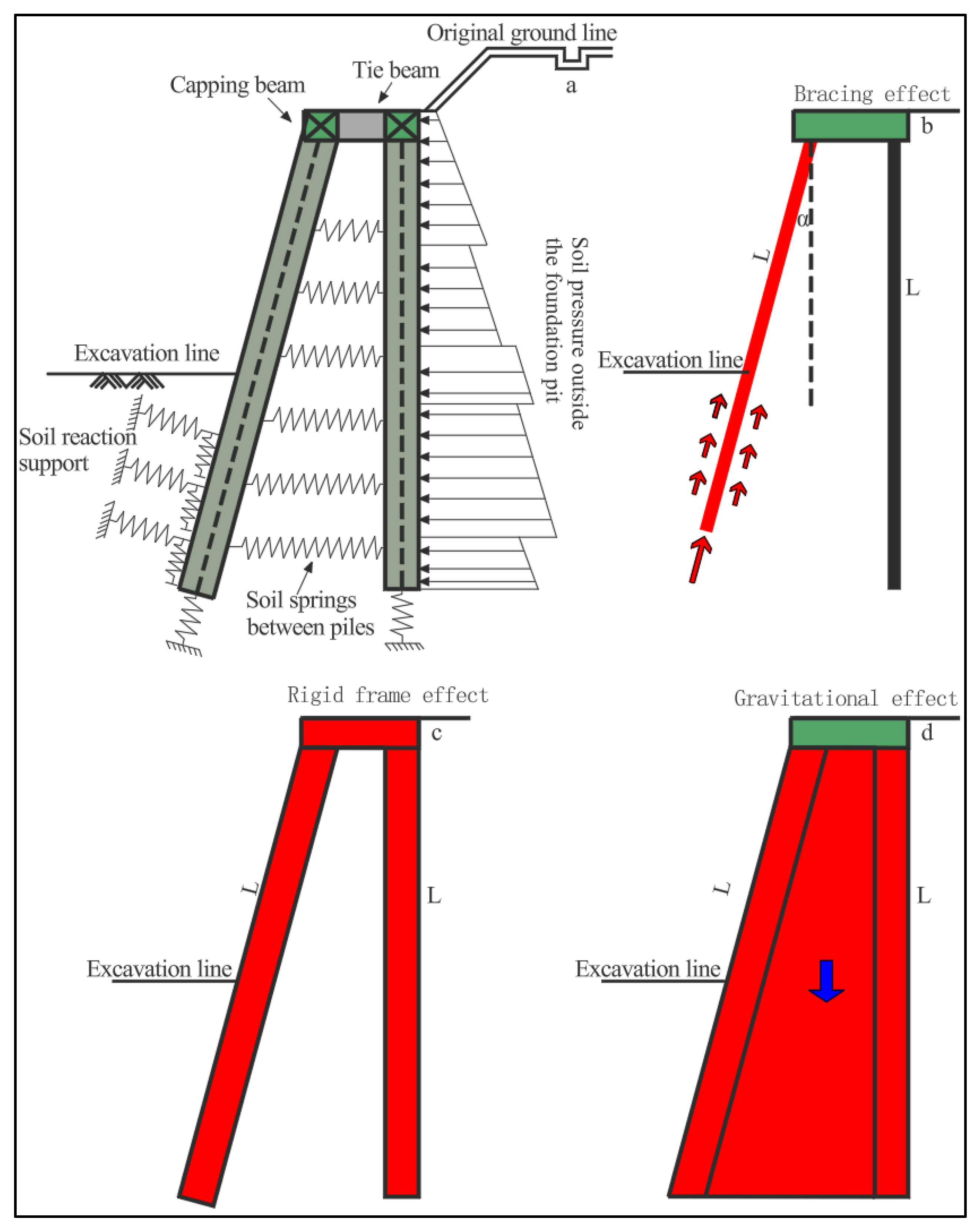
The combination of double-row piles, consisting of inclined front-row piles and vertical rear-row piles, represents an effective support system. These piles are interconnected through a capping beam and tie beam at their tops. The inclination of the front-row piles facilitates the conversion of horizontal earth pressure into axial force, reducing bending moments on the piles. Meanwhile, the vertical rear-row piles primarily resist vertical uplift forces and share bending moments. Together, they create a portal frame structure akin to a truss via the tie beam, promoting rigid-body displacement over bending deformation. This configuration enhances overall stiffness and effectively controls lateral displacement, offering economic benefits due to the compressive load-bearing characteristics. Refer to Figure 2 for visual representation.

2.2. Hardening Soil Constitutive Model (HS)

The HS constitutive model belongs to the elastoplastic model, which can accurately describe the nonlinear deformation, shear volume change, and progressive strength development characteristics of soil during foundation pit excavation. By introducing the stress-level-dependent nonlinear stiffness function, the dilatancy angle parameter, and the design of the yield surface adapted to the unloading path, the numerical simulation accuracy of predicting the deformation response and yield range of rock and soil masses is significantly improved [38]. Differentiated constitutive models are adopted for different states of the soil between piles. The HS model is used for the unreinforced soil to account for its nonlinear mechanical behavior, while the soil reinforced with cement is simplified as an elastic model to reflect the stiffness enhancement characteristics caused by the reinforcement effect [39]. This method simplifies the analysis process while ensuring the calculation accuracy.
Nonlinear elastic characteristics:
E 50 = E p r e f r e f ( σ 1 + p x p r e f + p x ) m
E u r = E u r r e f ( σ 1 + p x p r e f + p x ) m
E o e d = E o e d r e f ( σ 3 + p x p r e f + p x ) m
p x = c cot ϕ
σ 1 : major principal stress; σ 3 : minor principal stress; E 50 : confining stress-dependent stiffness modulus for first loading; E u r : Young’s modulus for unloading and reloading; E o e d : consolidated elastic modulus; P r e f : stiffness parameter stress; m: stress-dependent stiffness power law exponent; E 50 r e f : reference secant stiffness in standard hydraulic triaxial test; E o e d r e f : reference tangent stiffness for consolidated loading; and E u r r e f : reference unloading/reloading stiffness.
T. Schanz, P.A. Vermeer, and P.G. Bonnier [40] established the HS model based on the hyperbolic relationship between the deviatoric stress and the vertical strain in triaxial tests. Among them, the shear failure and the compression failure have no influence on each other. The yield function of the HS constitutive model consists of two parts: the shear yield function and the compression yield function, which are specifically as follows:
f 13 = 2 q α E i ( σ 1 σ 3 ) q α ( σ 1 σ 3 ) 2 ( σ 1 σ 3 ) E u r γ p = 0
E i : = 2 E 50 2 R f
q α : = 1 R f q f
q f : = 2 sin ϕ 1 sin ϕ ( σ 1 + c cot ϕ )
f c = q 2 α 2 + ( p + c cot ϕ ) 2 ( p c + c cot ϕ ) 2 = 0
f t = p p t
f 13 : shear yield function; E i : initial elastic modulus of rock mass; q a , q f : asymptotic and ultimate deviatoric stress; R f : failure ratio; q: deviatoric stress; γ p : plastic shear strain; f s , f c : shear and compression yield functions; p c : pre-consolidation pressure; p : average principal stress; and p t : tensile strength.
The plastic potential function and the flow rule, as well as the shear, compression, and tensile potential functions, are as follows:
g 13 = ( σ 1 σ 3 ) 2 + ( σ 1 + σ 3 ) 2 sin ψ m
g c = q 2 α 2 + ( p + c cot ϕ ) 2 , g t = p .
sin ψ m = sin ϕ m sin ϕ c v 1 sin ϕ m sin ϕ c v
sin ϕ m = σ 1 σ 3 ( σ 1 + σ 3 ) + 2 c cot ϕ
sin ϕ c s = sin ϕ sin ψ 1 sin ϕ sin ψ
g 13 : shear plastic potential function; g c : compression plastic potential function; ψ : dilatancy angle; ϕ : internal friction angle; ϕ m : mobilized friction angle; ϕ c s : critical friction angle; and ϕ c v : residual internal friction angle.
The HS constitutive model exhibits hardening characteristics with the increase of effective plastic strain and reaches an ideal plastic state under the action of the above yield function. During the compression hardening stage, the stress generated by the preconsolidation effect is defined as follows:
p c n + 1 = ( p c r e f + p x ) p c n + p x p c r e f + p x 1 m + 1 m p c r e f + p x H Δ ε v p 1 1 m p x
H = K s r e f K c r e f K s r e f K c r e f
K s r e f = E u r r e f 3 ( 1 2 v )
K c r e f = E o e d r e f 3 ( 1 2 v )
p c r e f : reference preconsolidation pressure; K s r e f : reference unloading bulk modulus; K c r e f : reference compression bulk modulus; and Δ ε v p : plastic volumetric strain.

3. Project Overview and Numerical Simulation

3.1. Project Overview

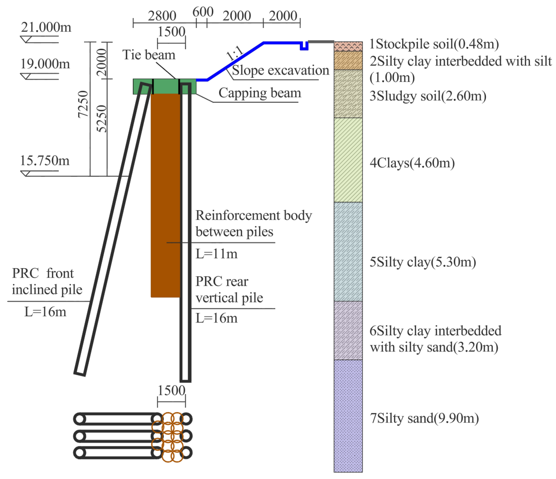
The foundation pit project for the Xiantao Citizen Service Center is situated at the junction of Qiantong Road and Mianzhou Avenue in Xiantao City. The foundation pit project covers an area of 8688 m2, with excavation depths of 5.15 m and 7.25 m at the local level. This project is cited as a reference case in the local standard of Hubei Province, specifically in the “Technical Specification for Inclined Pile Support of Foundation Pit.” Situated on the Hanjiang alluvial plain, the project site is positioned within the first terrace of the Hanjiang River. The topography is predominantly flat, and the distribution of strata is characterized by stability. From the surface to a depth of 30 m, the strata are ① stockpile soil (Qml); ② silty clay interbedded with silt (Q4ml); ③ sludgy soil (Q4l); ④ clays (Q4al); ⑤ silty clay (Q4ml); ⑥ silty clay interbedded with silty sand (Q4ml); and ⑦ silty sand (Q4ml). Fine sand is dominant below 30.0 m. Groundwater at the site is divided into two categories: upper stagnant water and confined water. Below 30 m, fine sand predominates. The site’s groundwater is categorized into two types: upper stagnant water and confined water. The upper stagnant water is found in the plain fill layer, with the groundwater level approximately 1 m deep. Confined water is present in layers 6 and 7, with a groundwater level about 3 m deep, and its volume remains relatively stable. The primary recharge source for the groundwater is the lateral runoff from the Hanjiang River and its surrounding regions.
In this study, a double-row pile retaining system comprising inclined front-row piles and vertical rear-row piles is utilized in the deep excavation zone. The retaining piles consist of precast PRC-Ⅰ-600-AB (110) type new hybrid-reinforced prestressed concrete pipe piles. This novel composite reinforced pile combines prestressed concrete with nonprestressed reinforcement, enhancing its flexural and shear resistance properties and ductility significantly. The measured ultimate flexural bearing capacity is 522 kN·m, while the shear bearing capacity is 470 kN. This system offers advantages such as enhanced construction efficiency, environmental sustainability, ease of inspection, and the potential for prefabrication in controlled factory settings.
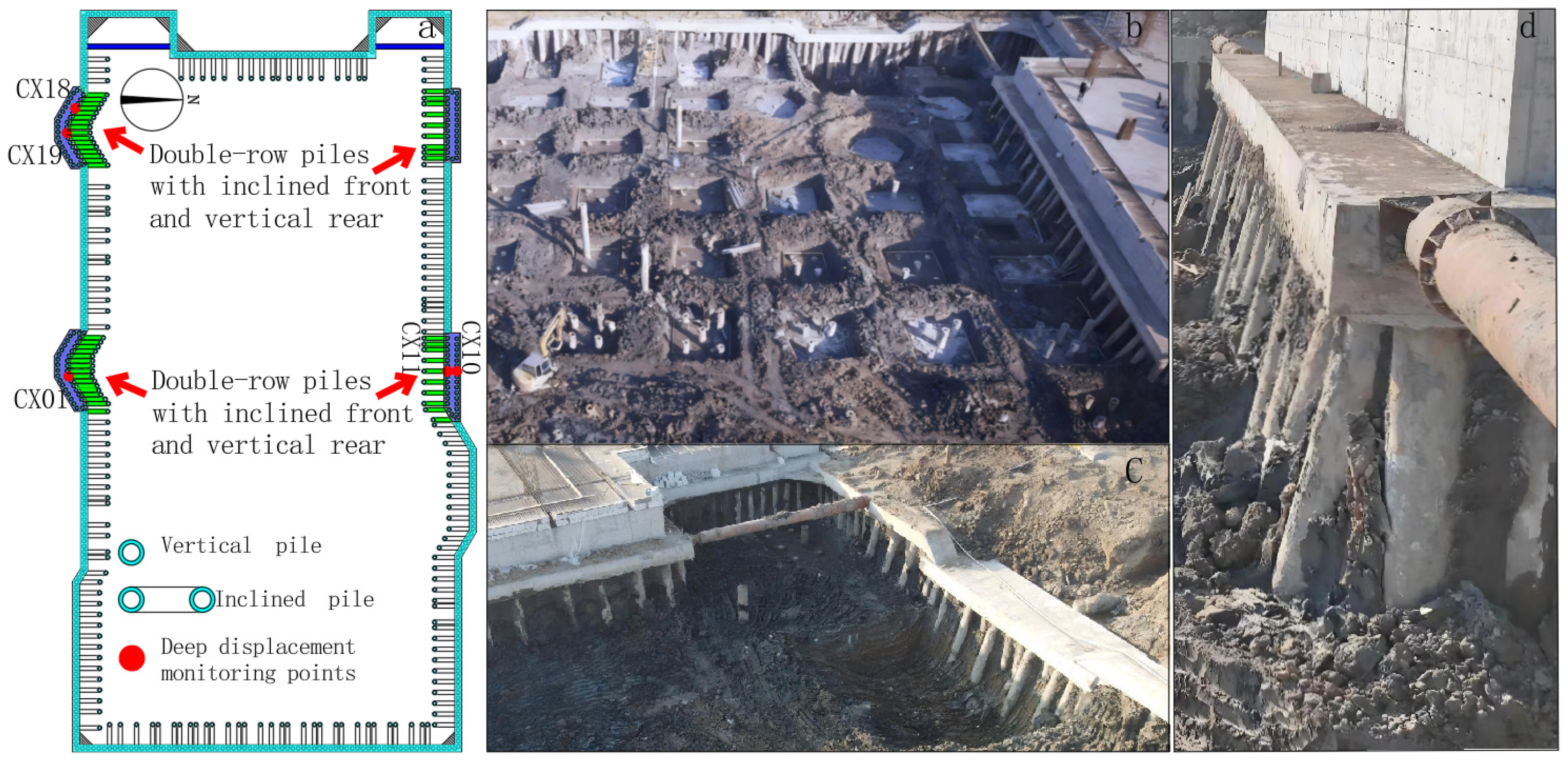
The support system is designed with specific parameters as outlined below: the front-row piles are inclined at an angle of 13°, while the rear-row piles are vertical. All piles have a length of 16 m, a spacing of 0.9 m, and a 1.5 m separation between the front and rear rows. The soil between the piles is reinforced vertically by double-pipe high-pressure jet grouting piles with a diameter of φ700@500 mm, reaching a depth of 11 m. The foundation pit support’s plane layout and monitoring point distribution are illustrated in Figure 3, with a depiction of the typical support structure’s cross-section provided in Figure 4.

3.2. Numerical Simulation

3.2.1. Numerical Model Establishment

This study established a three-dimensional numerical model, as shown in Figure 5, based on the Midas GTS NX geotechnical engineering finite element analysis platform. To effectively eliminate the influence of boundary effects, the model scope was determined according to the following principles: in the long-axis direction of the foundation pit, it was extended to three times the excavation depth, and in the depth direction, it was extended to twice the length of the retaining piles, forming a quasi-infinite domain calculation space with a length of 50 m, a width of 30 m, and a height of 34 m [41]. The boundary conditions were set following the basic principles of geotechnical numerical analysis: the top surface of the model was set as a free boundary; normal displacement constraints were applied to the four lateral boundaries. Full fixed constraints were adopted for the bottom surface [42]. The soil mass was modelled using solid elements, a 1 m grid size. The support piles were modelled with a 0.5 m grid size. Tetrahedral elements were used throughout. The total model had 78,826 nodes and 102,670 elements. Support piles, crown beams, and connecting beams were modelled using beam elements, and the concrete spray surface was modelled using plate units. The excavation process for the foundation pit was simulated using the layered excavation method, with an excavation thickness of 2 m for each layer.
The mechanical parameters of the soil material and the support structure are shown in Table 1 and Table 2, respectively.

3.2.2. Numerical Analysis Procedure

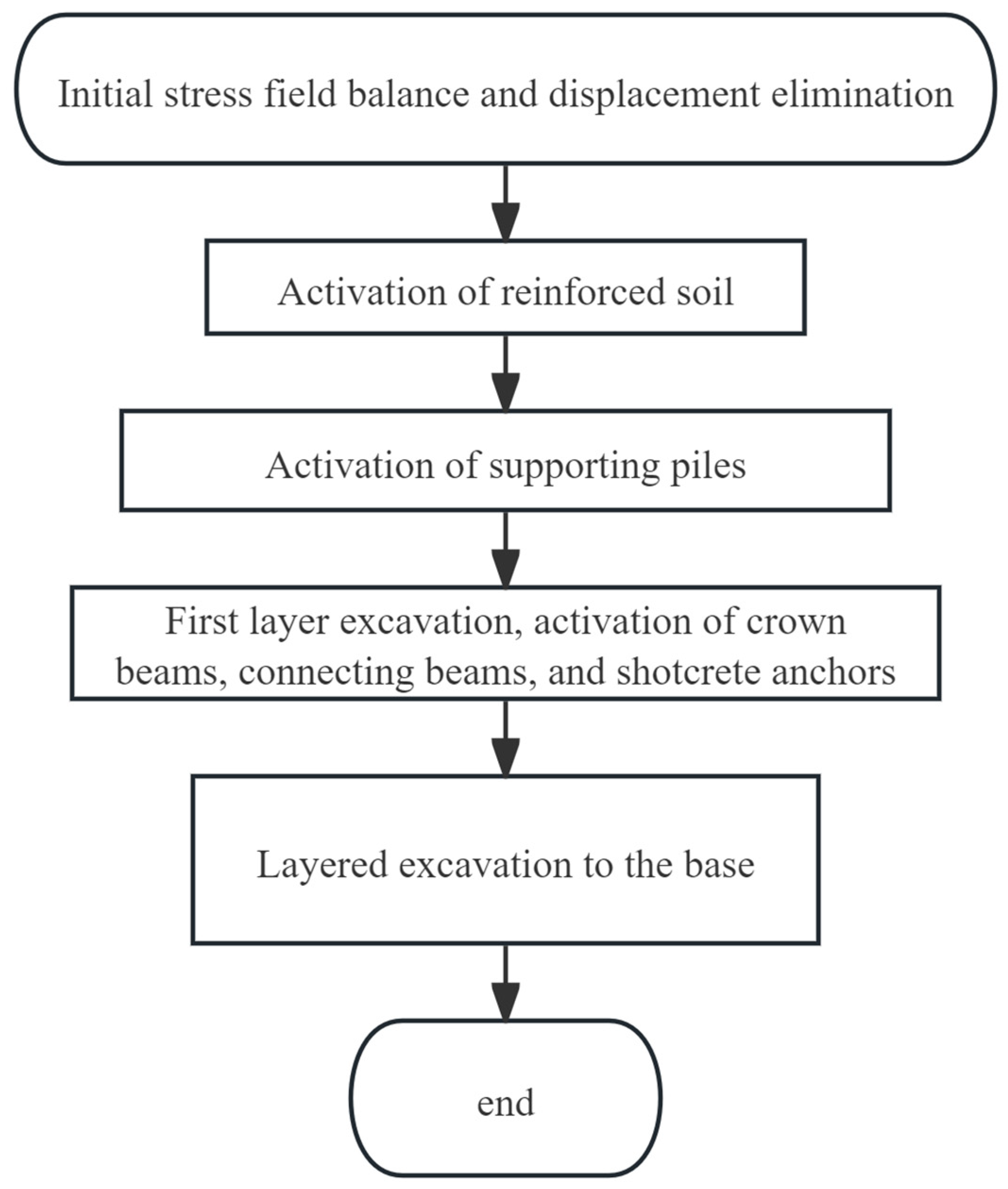
To best conform to the actual construction conditions of the foundation pit, the analysis settings for this time are as shown in Figure 6:
(1) Import the layout plan of the foundation pit support to generate a geometric model of soil and soil support parameters. The foundation pit model is split into grids (a 1 m grid size), and the area around the support piles is reduced to 0.5 m. Support piles, crown beams, and connecting beams are represented by beam elements obtained from the soil model; slope release shotcrete anchor is represented by plate elements obtained from the soil model. Certain construction boundary conditions are applied to the reinforcement area between piles after construction is completed. The soil properties change from ordinary to reinforced soil after the construction steps. (2) Establish boundary conditions: The top surface of the model is a free boundary, normal displacement constraints apply to the four sides, and fully fixed constraints apply to the bottom surface. Self-weight load of soil introduced. (3) Calculate initial stress field, activate soil grid, apply constraints and self-weight load, and eliminate initial strain. (4) Build soil for inter-pile reinforcement, activate attributes and boundary conditions, and activate support pile grid. (6) Excavate foundation pit 2 m deep, activate crown beam, connecting beam, and slope spray surface, and excavate foundation pit 4 m deep. (8) Excavate foundation pit 6 m deep, and (9) Excavate foundation pit to desired base elevation.

3.3. Mesh Size Sensitivity Analysis

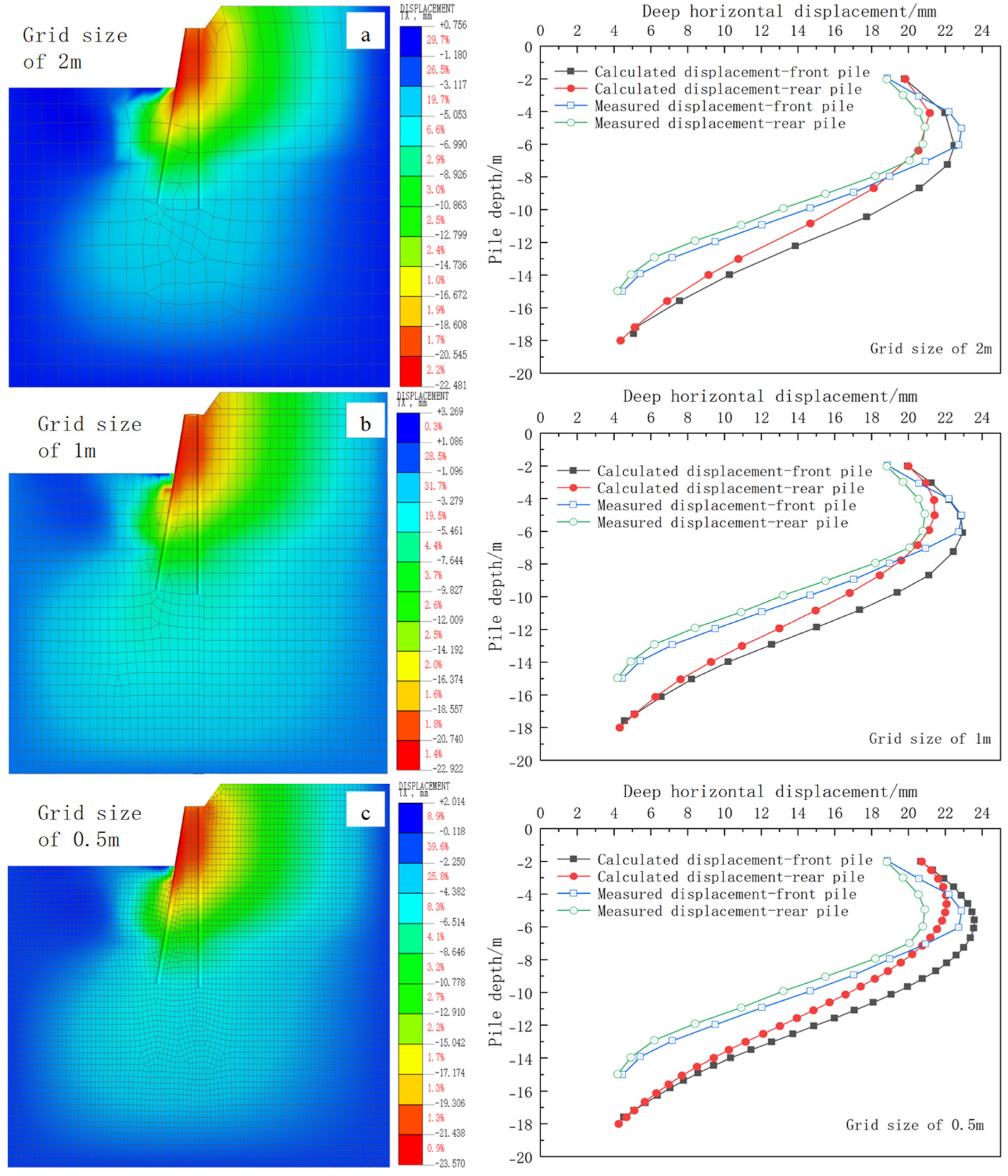
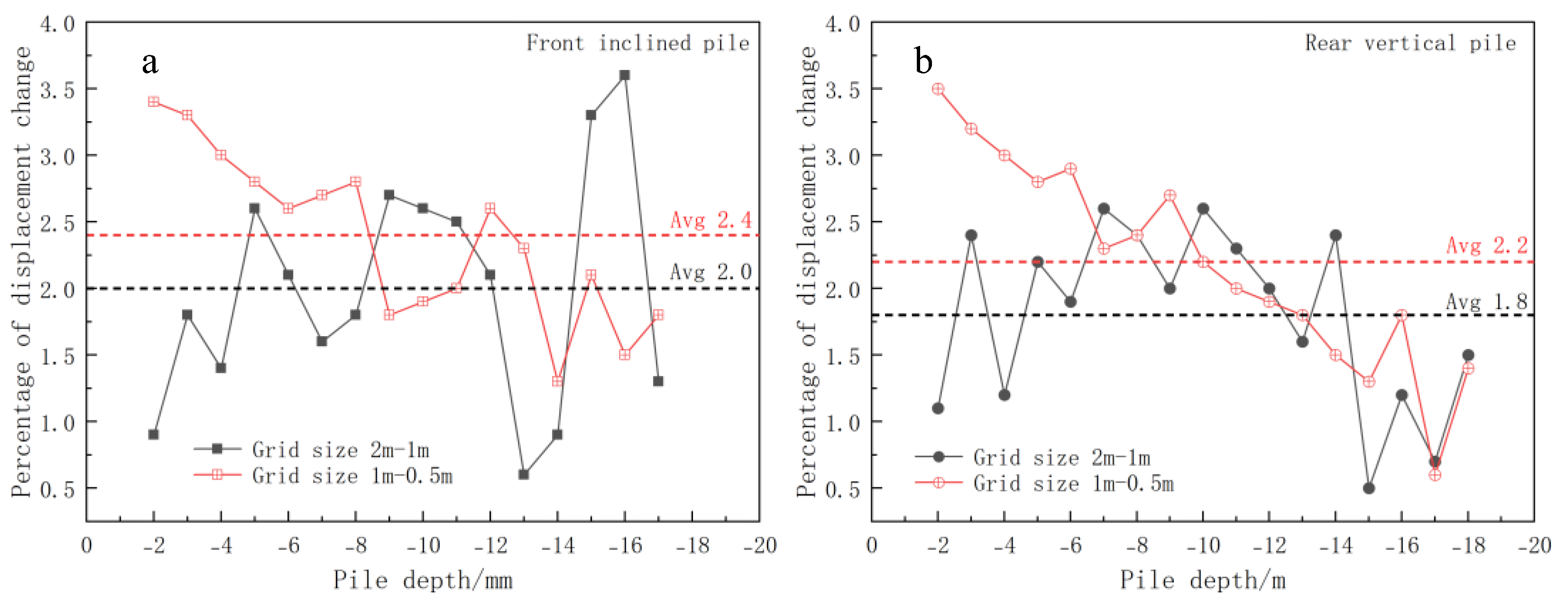
This article conducts analyses using three grid sizes: 2 m, 1 m, and 0.5 m, respectively. Comparison of calculated curves of pile body displacement under different grid sizes and measured values yielded the following results: For the adjustment of the grid size to 2 m, the average error rate of the calculated displacement of pile body to 1 m was 1.9%; when adjusted to 1 m and 0.5 m, the average error rate was 2.3%, as shown in Figure 7, Figure 8 and Figure 9. The finer the grid, the greater the variation range of calculated displacement of the pile shaft. The maximum displacement of the pile body calculated with a 2 m grid is smaller than the measurement result of monitoring, and therefore, grid division is not suitable for finite element calculations. The calculation result of a 1 m grid is far more in agreement than the actual monitoring result. The calculation result of a 0.5 m grid is slightly larger than the measured result, which meets some requirements for safety reserves in engineering applications. In summary, we use a 1 m grid for the overall division, and a 0.5 m grid for the main analysis areas such as support piles and inter-pile reinforcement zones. This grid can not only guarantee a good agreement between the calculation results and the monitoring data, but also better reflect the deformation characteristics of the support structure.

3.4. Comparative Analysis of Results

Figure 10 presents a comparative analysis of three sets of displacement data alongside two sets of stress-related results. The displacement data comprises: (1) finite element calculation results from existing literature, (2) on-site monitoring data of double-row piles configured with an inclined front row and a vertical back row, and calculation results from the finite element model developed in this study. The stress-related analysis entails a comparison between the measured earth pressure in the earth pressure box and the finite element calculation values, as well as a comparison between the bending moment derived from the steel bar stress gauge and the bending moment predicted by the finite element model of the pile shaft. The comparison results indicate that the horizontal displacement behavior of the pile body simulated in this study aligns closely with the literature findings and exhibits even greater consistency with the actual on-site monitoring data. Furthermore, the stress simulation results demonstrate a high degree of agreement with the measured values. This consistency substantiates the reliability of the model established in this paper and offers valuable insights for examining the impact of inter-pile reinforcement parameters on the displacement and internal forces of the support structure.
The absolute error analysis of pile shaft displacement presented in Figure 11a,b confirms the calculation accuracy of the proposed method. In comparison to the reference method, which yields mean absolute errors (MAE) of 4.34 and 3.86, the MAE derived from the method described in this paper is significantly lower at 2.76 and 2.79. Furthermore, the error fluctuation characteristics align more closely with the on-site monitoring values, enabling a more precise depiction of the settlement response at varying pile depths. The fitting results of the calculated values against the on-site monitoring values (Figure 11c,d) further reveal that the determination coefficients for the front-inclined pile and the rear-vertical pile are 0.983 and 0.984, respectively, with root mean square errors of 2.09 mm and 2.91 mm. Additionally, all data points fall within the 95% confidence zone and the prediction zone. This evidence robustly demonstrates the strong linear correlation and numerical consistency between the calculation results of the proposed method and the actual monitoring data. Collectively, these findings substantiate the accuracy and engineering applicability of the proposed method for predicting pile shaft deformation, thereby providing a reliable foundation for subsequent related research, as shown in Figure 11.

4. Study of the Displacement Characteristics and Influencing Factors of Inclined-Front, Vertical-Rear, Double-Row Piles

4.1. Inclination Angle’s Influence on Support System Deformation

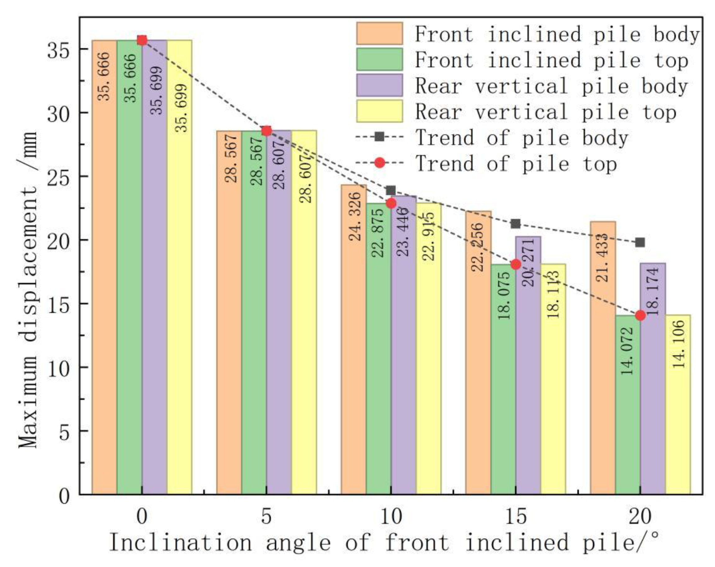
Significant disparities exist in displacement response characteristics between double-row piles featuring inclined front piles and vertical rear piles compared to vertical double-row piles. The top displacement of vertical double-row piles is 35.70 mm, and the top displacement of double-row piles with the front row inclined and rear row vertical is 18.11 mm. The top displacement of this pile is 49% lower than the top displacement of the previous piles. Vertical double-row piles demonstrate typical cantilever deformation traits, with the maximum horizontal displacement occurring at the pile top, which notably increases with greater excavation depth. The displacement distribution of double-row piles with inclined front piles and vertical rear piles displays a drum-shaped pattern that is convex towards the excavation face, with the point of maximum displacement situated near the excavation face. Apart from the pile top region, the displacement in the inclined front piles consistently surpasses that of the vertical rear piles. Furthermore, as excavation depth increases, the discrepancy in displacement between the two types exhibits a continuous expanding trend, as illustrated in Figure 12.
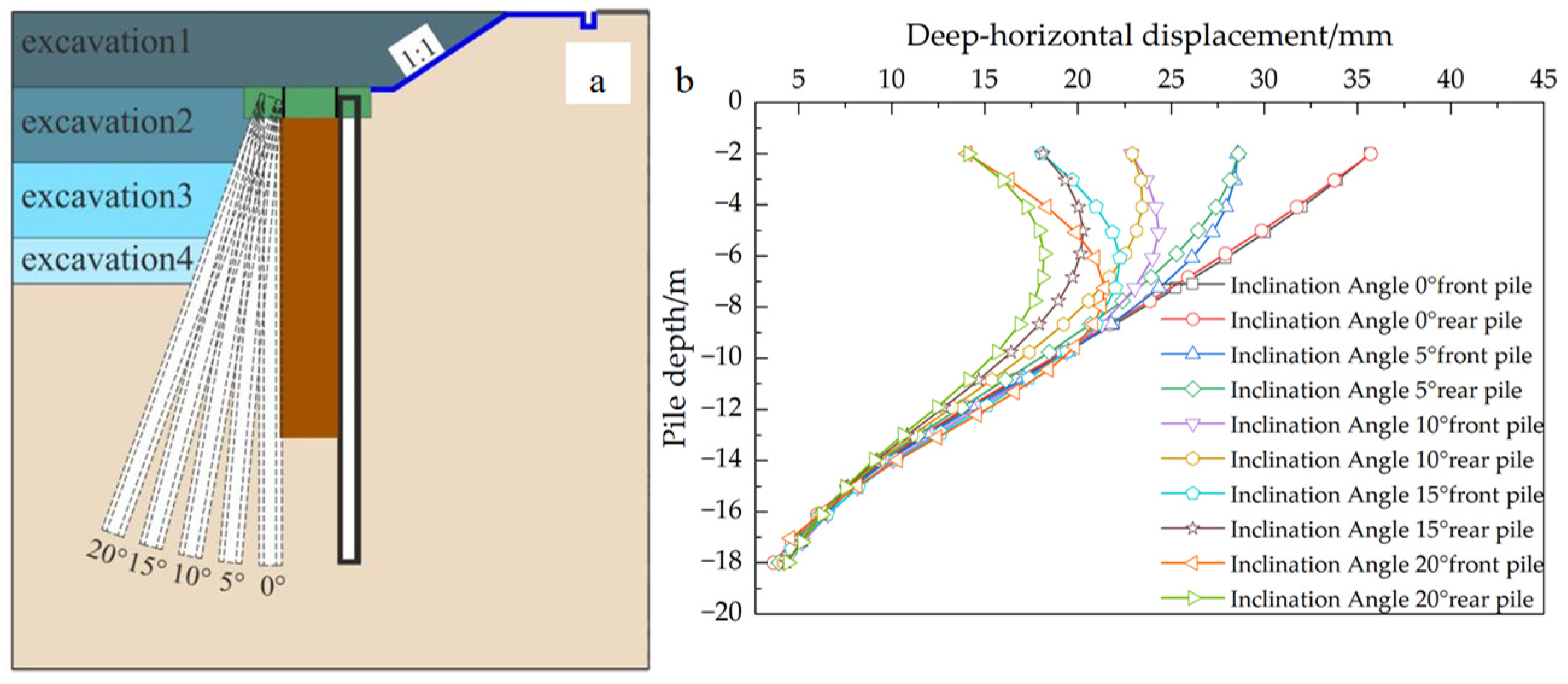
This study conducted a comparative analysis of the displacement characteristics of double-row piles with front-row pile inclination angles ranging from 0° to 20°, in addition to vertical double-row piles, as depicted in Figure 13 and Figure 14. The findings indicate that an increase in the inclination angle of the front-row inclined piles results in a gradual convergence of the displacement characteristics towards those of the pile-support retaining system. The front-row inclined piles exhibit a behavior akin to inclined supports, with a more pronounced supporting effect observed at larger inclination angles. This effect leads to reduced overall displacement of the support system and a shift in the position of the maximum displacement of the pile body towards the excavation face. Through an assessment of the displacement control effect, an inclination angle of 20° is identified as the optimal parameter for the front-row piles. This angle establishes the baseline scenario for subsequent optimization studies on the soil reinforcement parameters between piles.

4.2. Influence of the Top Crown Beam of Piles and the Soil Between Piles on the Deformation of the Retaining and Protecting System

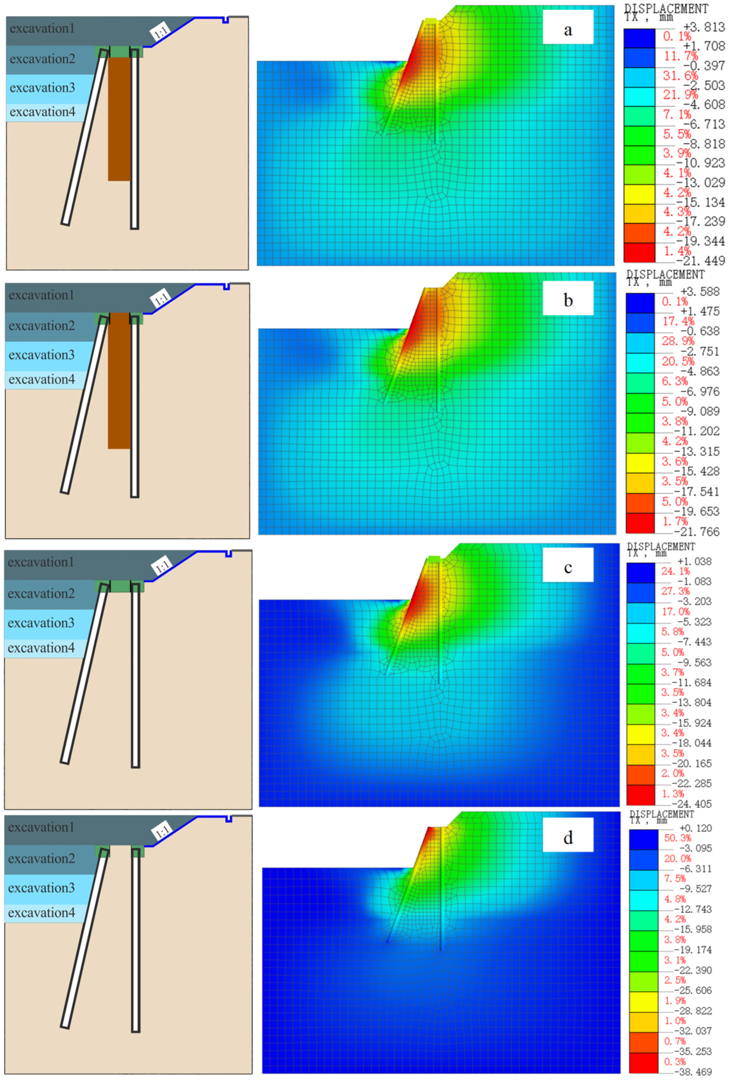
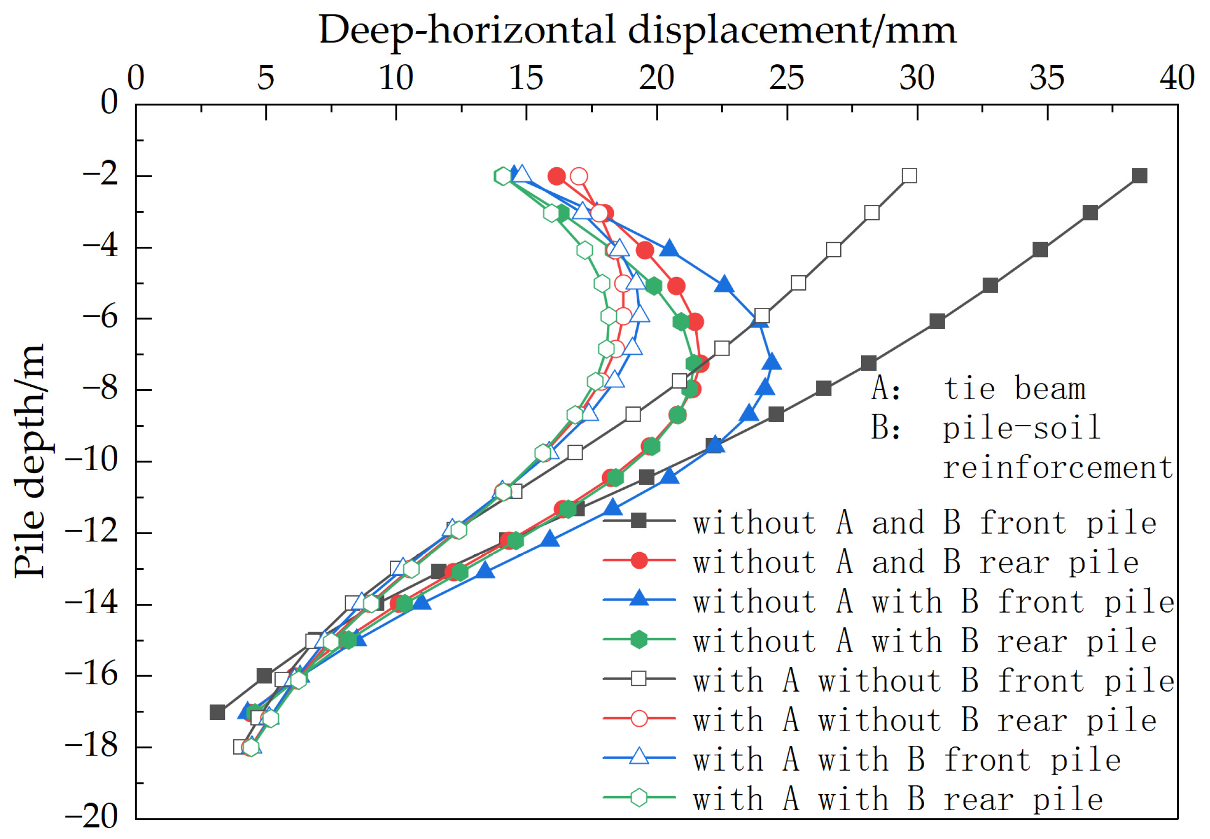
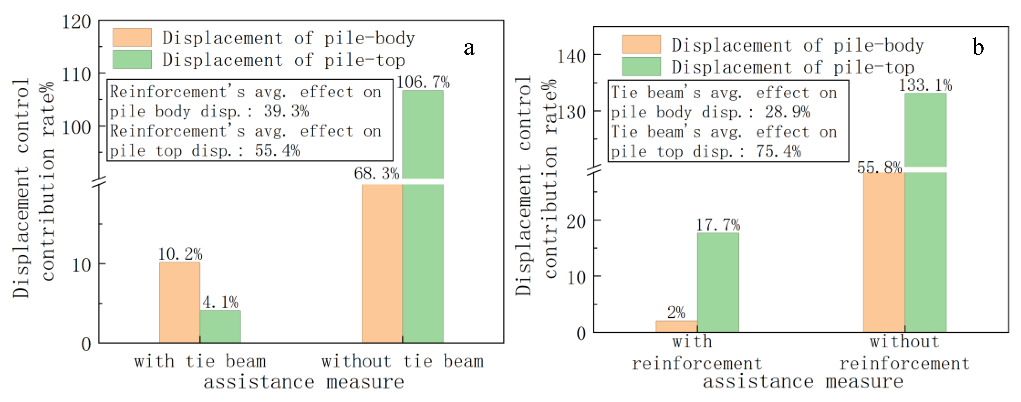
The deformation characteristics of the double-row pile supporting structure with front inclined and rear vertical piles are affected by both the pile tie beam and the reinforcement of soil between piles. However, there are significant differences in the mechanical essence between these two constraint mechanisms. The tie beam forms an overall flexural mechanism of the spatial rigid frame structure by establishing rigid connection nodes between the front and rear rows of piles. The reinforcement of the soil between piles significantly enhances the horizontal resistance coefficient of the soil on the pile side by improving the mechanical parameters of the pile–soil contact surface. This study takes the working condition with both tie beams and soil reinforcement between piles as the benchmark and systematically analyzes the contribution of the two to the deformation of the retaining structure, as shown in Figure 15, Figure 16 and Figure 17. Figure 18 shows that the average contributions of soil reinforcement between piles to reduce the deformation of the pile body and the pile top are 39.3% and 55.4%, respectively, while the average contributions of the tie beams to reducing the deformation of the pile body and the pile top are 28.9% and 75.4%, respectively. Therefore, the reinforcement between piles plays a dominant role in controlling the overall displacement of the pile body, while the tie beam mainly regulates the displacement of the pile top. It is noteworthy that the removal of both the tie beam and the soil reinforcement between piles results in a significant transformation in the displacement pattern of the retaining and protection system. Specifically, the shift is observed from a “concave-inward” distribution to a “cantilever” distribution. This abrupt change is attributed to a sudden 50% reduction in lateral resistance following the removal of constraint conditions. Consequently, the structural system transitions from a collaborative force-bearing mode to an independent bearing mode of single piles.

5. Parameter Analysis of Reinforcement Between Inclined-Front, Vertical-Rear, Double-Row Piles

5.1. Influence of Reinforcement Range on Deformation Characteristics of the Support System

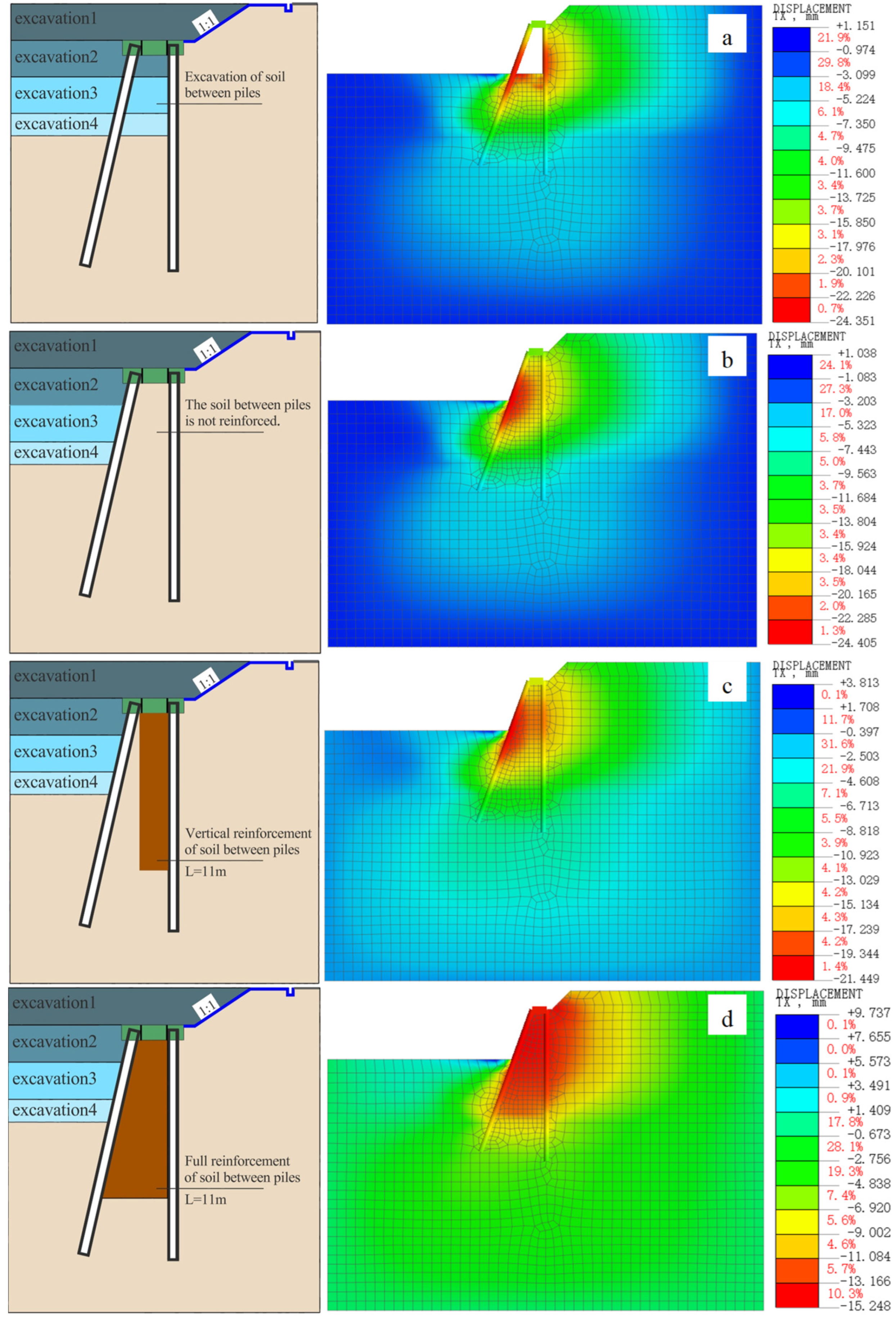
This study systematically analyzed the displacement response characteristics and mechanical mechanisms of the front and rear rows of piles under four typical working conditions (no reinforcement, excavation of soil between piles, vertical reinforcement, and full-range reinforcement), as shown in Figure 19.
The research results show that the displacement of the front-row inclined piles is ranked as follows: the non-reinforcement condition (maximum) > the excavation condition of the soil between piles > the vertical reinforcement condition > the full-range reinforcement condition (minimum). For the rear-row vertical piles, the displacement pattern is as follows: the excavation condition of the soil between piles (maximum) > the non-reinforcement condition > the vertical reinforcement condition > the full-range reinforcement condition (minimum), as shown in Figure 20.
This difference stems from the distinct force-bearing mechanisms of the two types of piles.
The displacement of front-row inclined piles is primarily governed by the dynamic equilibrium between earth pressure and the lateral reaction force of the soil within the piles. Under unreinforced conditions, displacement is maximized due to inadequate lateral restraint. Excavation between the piles decreases active earth pressure but diminishes lateral frictional resistance. Vertical reinforcement enhances the stiffness of the local soil, leading to a notable reduction in displacement. Full-range reinforcement minimizes displacement by optimizing pile–soil interaction to establish a stable force transmission pathway.
The displacement behavior of the rear-vertical pile row is contingent upon the interplay between the supportive stiffness of the front-inclined pile row and the lateral soil resistance between the piles. Soil excavation between the piles notably diminishes the supporting efficacy of the front pile row, leading to the most substantial displacement in the rear row. Under unreinforced circumstances, displacement ranks as the second highest due to constrained soil support. Vertical reinforcement mitigates displacement by enhancing local stiffness, with comprehensive reinforcement offering the most effective balanced constraint.
Research has established that employing a full reinforcement scheme yields the most effective displacement control for both front and rear rows of piles. This approach enhances interaction between the piles and the soil and increases lateral restraint. Conversely, the absence of reinforcement and excavation of soil between piles alters the stress equilibrium within the pile–soil system, leading to notable disparities in displacement behavior between reinforced and non-reinforced piles.
In engineering applications, the selection of reinforcement methods should align with the mechanical properties of the supporting structure. Full-range reinforcement stands out as the most effective approach for managing the displacement of the support structure.

5.2. Analysis of the Depth of Reinforced Soil Between Piles

5.2.1. Influence of Reinforcement Depth on Pile Displacement

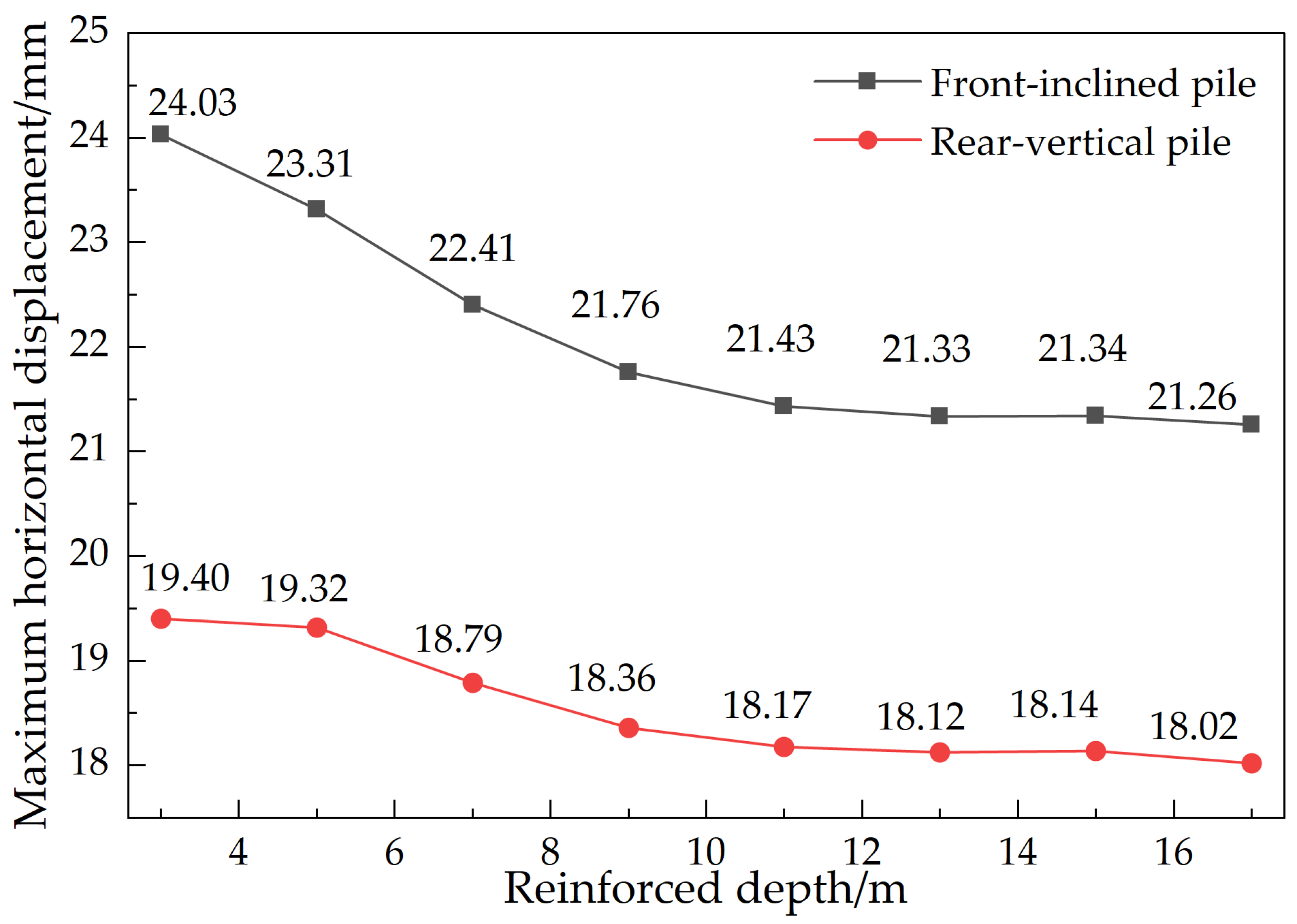
Under the vertical reinforcement condition, with the increase of the reinforcement depth, the horizontal displacements of the front-row inclined piles and the rear-row vertical piles both decrease significantly. When the reinforcement depth increases from 0 to 1 times the pile length, the maximum displacements of the front-row inclined piles and the rear-row vertical piles decrease from 24.03 mm and 19.40 mm to 21.26 mm and 18.02 mm, respectively, with reduction rates of 11.5% and 7.1%, respectively. From the change process, the displacement decreases most significantly before the reinforcement depth reaches 1/2 pile length; the displacement reduction rate slows down in the interval from 1/2 to 3/4 pile length; and when the reinforcement depth exceeds 3/4 pile length, further displacement changes tend to be gentle, indicating that the effect of continuous deepening reinforcement on displacement control is very limited at this time, as shown in Figure 21.
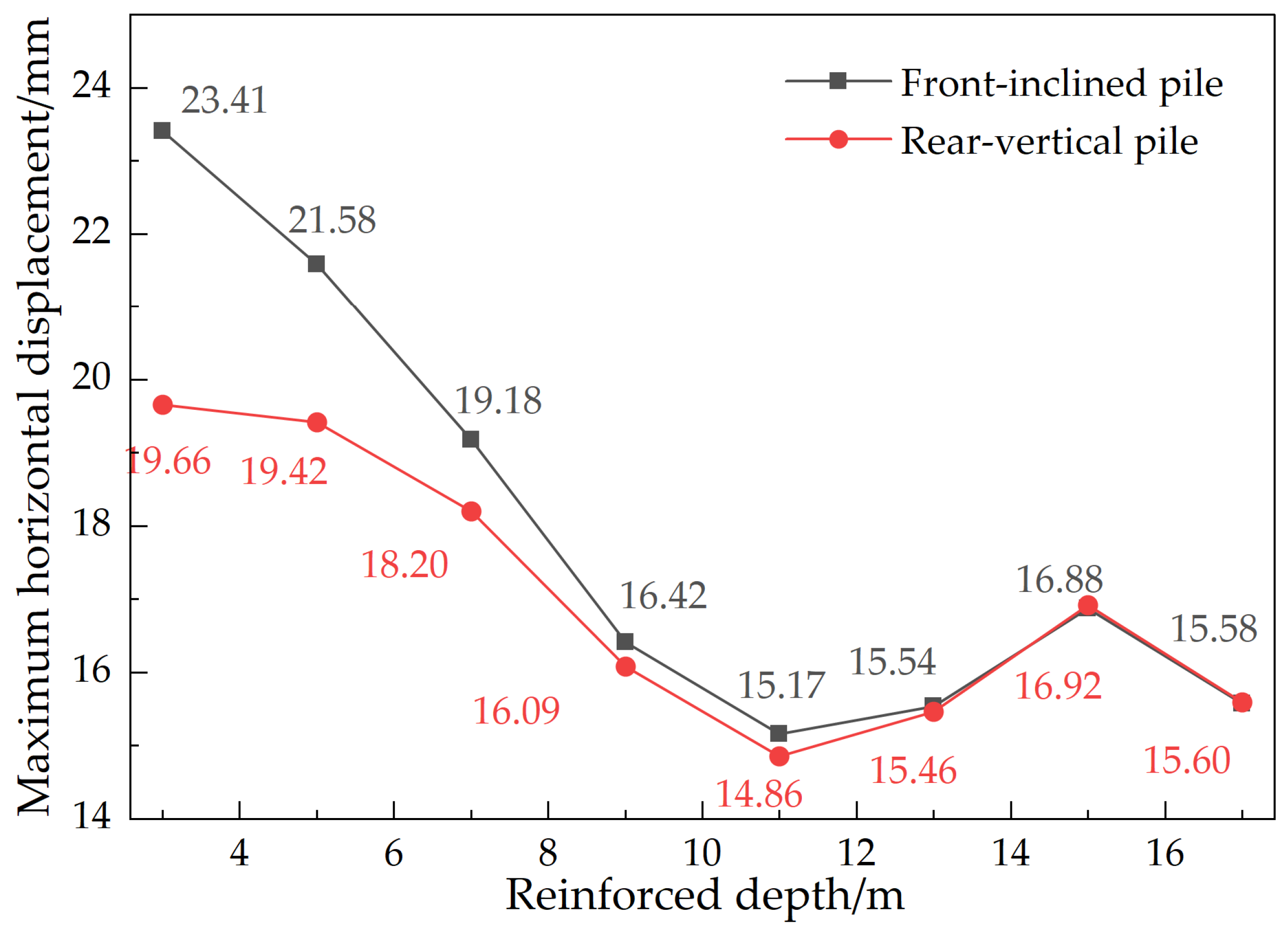
Under the full reinforcement condition, the lateral displacement of the support system exhibits distinct three-stage characteristics as the reinforcement depth varies, as depicted in Figure 22. This phenomenon is intricately linked to the interplay between the reinforcement depth and the length of the pile.
Initial stage (0–3/4 pile length): As reinforcement depth decreases from 0 to 3/4 of the pile length, the displacement of the support system decreases. Front inclined pile displacement decreases from 23.41 mm to 15.17 mm (roughly 35%), and rear vertical pile displacement decreases from 19.66 mm to 14.86 mm (roughly 24%). This disparity highlights the greater sensitivity of inclined piles to soil reinforcement.
Transition stage (3/4–1 pile length): An abnormal increase in pile body displacement occurs when the reinforcement depth ranges from 3/4 to the full length of the pile. This phenomenon is attributed to the proximity of the reinforcement area to the pile base, leading to a sudden transition in the pile-end constraint conditions from elastic embedding to fixed constraint.
Stable stage (greater than 1 pile length): When the depth of reinforcement exceeds the length of the pile, the displacement decreases once more. This results in the formation of a rigid bearing layer beneath the pile tip, with a thickness exceeding 1 m. Consequently, this formation significantly augments the rotational resistance at the pile tip and enhances the overall stiffness of the pile structure. For instance, at a reinforcement depth of 17 m, the maximum displacement of the support system mirrors that observed at a depth of 13 m.
Research indicates that optimal reinforcement depth for controlling displacement of the supporting system lies within the range of 0.75 to 1 times the pile length when the soil between piles is fully reinforced. Within this range, a reduction in supporting system displacement by 30% to 35% can be achieved, resulting in the highest economic efficiency. Anomalous displacement occurrences within the range of 3/4 to 1 times the pile length should be carefully monitored and mitigated during the design phase by adjusting the reinforcement ratio of the pile or modifying reinforcement parameters. While ultra-deep reinforcement beyond 1.0 times the pile length can further decrease displacement, it comes at a significant reduction in economic benefits.

5.2.2. Influence of Reinforcement Depth on Pile Bending Moment

Under the vertical reinforcement condition, the internal bending moment of the pile decreases as the reinforcement depth increases. The stress characteristics are primarily influenced by the ratio of reinforcement depth to excavation depth (h/H), as shown in Figure 23. For h/H < 1, the maximum bending moment of the front-row inclined piles surpasses that of the back-row vertical piles, accounting for 51.8 ± 0.7% of the total bending moment in the system, thus serving as the primary load-bearing elements. Conversely, when h/H ≥ 1, the maximum bending moment of the back-row vertical piles exceeds that of the front-row inclined piles by 4%. This shift occurs due to the deep reinforcement of the soil mass causing the passive zone’s center of gravity constraint to move downward. Consequently, the relative stiffness ratio of the pile–soil increases, leading to a higher bending moment load distribution ratio for the back-row piles. This stress transfer mechanism is particularly notable in sandy clay layers.
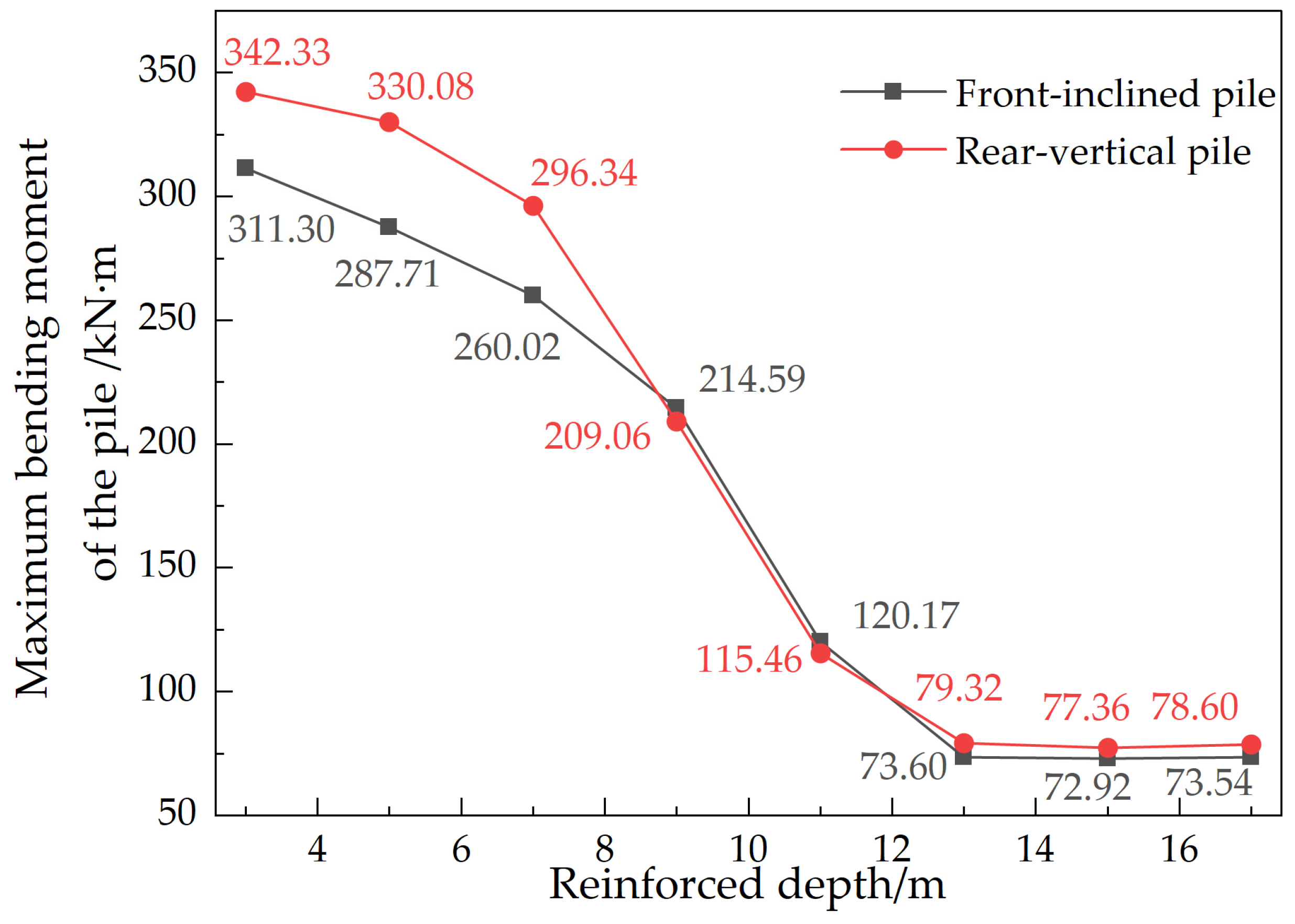
Figure 24 illustrates the behavior of pile body moment under full reinforcement conditions concerning the ratio of reinforcement depth to excavation depth (h/H). The analysis reveals a four-stage pattern: When h/H is in [0.4, 1), the front pile bends from 311.30 kN·m to 260.02 kN·m with a decrease of 16.5%. The rear pile bends from 342.33 kN·m to 296.34 kN·m, with a decrease of 13.5%. During this phase, reinforcement primarily impacts the soil in the active area. As h/H ranges from 1 to 1.5, the system transitions to a core regulation phase, the front pile is bending from 260.02 kN·m to 120.17 kN·m, which is about 53% lower than the front pile, while the rear pile is bending from 296.34 kN·m to 115.46 kN·m, which is about 61% lower than the front pile, defining the optimal reinforcement range. Beyond h/H > 1.5, the efficacy of increasing reinforcement depth on pile stress improvement plateaus. Notably, for h/H > 1.2, the moment distributions of front and rear pile rows converge, indicating a stress-balanced state in the supporting system and a tendency towards uniform soil stiffness distribution. In summary, the peak optimization of stress in the supporting system is achieved when the reinforcement depth reaches 1 to 1.5 times the excavation depth.

5.3. Sensitivity Analysis of Reinforcement Depth

In this paper, we present a single-factor sensitivity analysis based on multi-condition numerical simulation results using the normalized sensitivity coefficient formula. Reference conditions are determined with reinforcement depth of 11 m and solid elastic modulus of 200 MPa.
The normalized sensitivity coefficient formula:
S = ( R i R r e f ) / R r e f ( P i P r e f ) / P r e f
S : sensitivity coefficient
R i : response value after parameter change
R r e f : reference response value
P i : parameter value after change
P r e f : reference parameter value
The sign of the sensitivity coefficient indicates the relationship between the direction change of the parameter and the target response. The positive sign indicates that both directions change in the same direction, and the negative sign indicates that both directions change in the opposite direction. Parameters can be classified according to their sensitivity into three groups: highly sensitive parameters (|S| > 1.0), moderately sensitive parameters (0.5 < |S| ≤ 1.0), and lowly sensitive parameters (|S| ≥ 0.5).
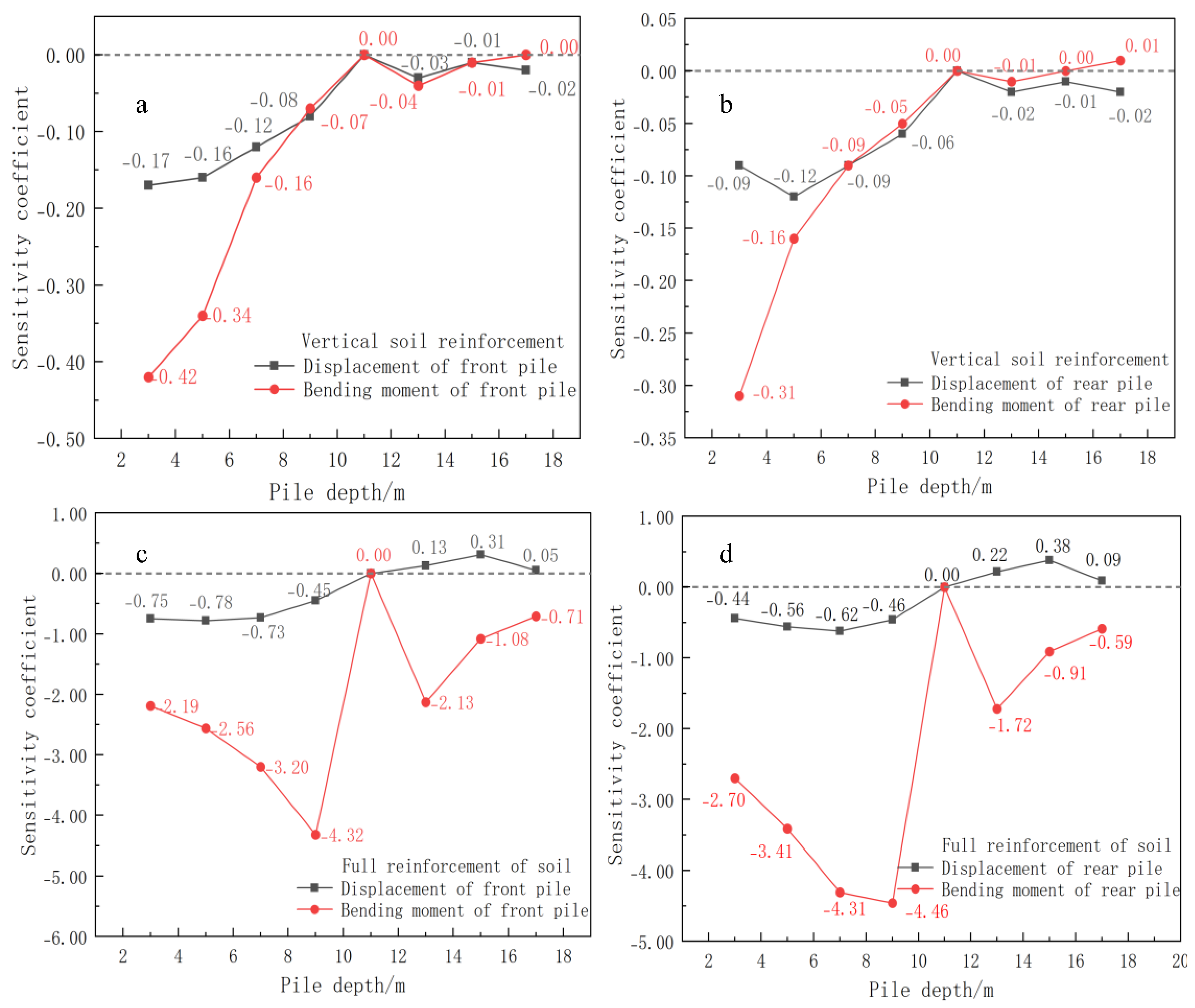
Based on the calculation results presented earlier, the sensitivity coefficients of reinforcement depths in relation to the displacement and bending moment of front-inclined and rear-straight double-row piles are shown in Figure 25.
As can be seen from Figure 25, reinforcement depth, displacement, and bend moment of front-inclined and rear-straight double-row piles tend to have opposite change (sensitivity coefficients mostly negative). In vertical reinforcement, the sensitivity coefficients tend to be moderate to low, while in full-range reinforcement, they are highly sensitive. The effect of reinforcement depth on the bending moment of piles is more important than displacement, and on rear-row piles slightly more than front-row piles. When the reinforcement depth is between 13 and 17 m, the absolute value of the sensitivity coefficient decreases significantly, and the reinforcement effect is greatly weakened. Ultra deep reinforcement (>1.5 times excavation depth) cannot significantly reduce the displacement of the pile body but will significantly increase the cost. Calculated with the 700 double pipe high pressure jet grouting piles at 140 yuan/m and total reinforcement length between piles of 100 m, for every 1 m increase in the reinforcement depth of the vertical reinforcement scheme (3 row piles), the cost increases by CNY 42,000 for every 1 m increase, while for full reinforcement condition (8 row piles), cost increases by CNY 112,000 for every 1 m increase.

5.4. Analysis of the Elastic Modulus of Soil Reinforcement Between Piles

5.4.1. Influence of Elastic Modulus on Pile Displacement

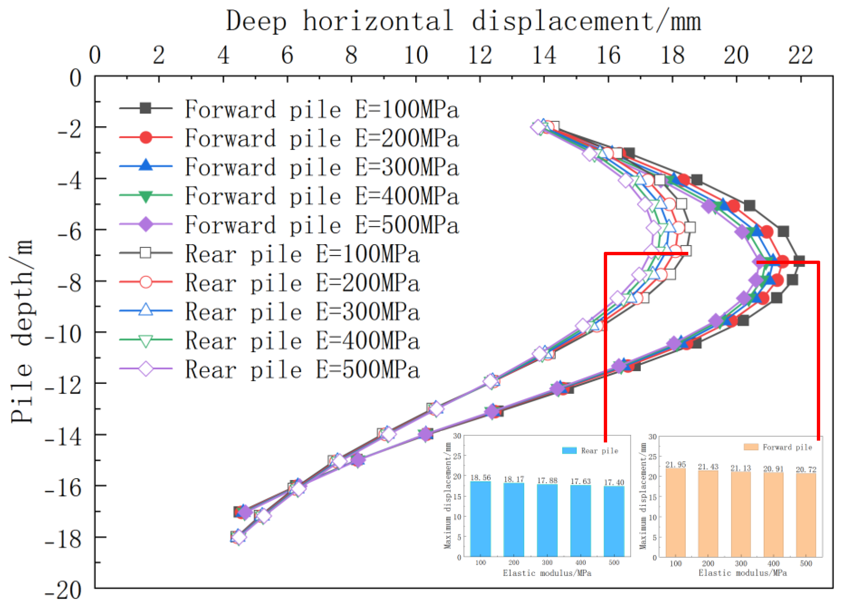
Under the condition of vertical reinforcement, increasing the elastic modulus of the in-pile reinforcement body significantly reduces the displacement of the pile body. As illustrated in Figure 26, with an increase in the elastic modulus of the soil between piles from 100 MPa to 500 MPa, the front pile displacement decreased by 5.6% from 21.95 mm to 20.72 mm. The rear pile displacement decreased by 6.3% from 18.56 mm to 17.40 mm. This indicates that enhancing the soil stiffness effectively limits the deformation of the pile body. The displacement of the front-row piles typically exceeds that of the back-row piles by 15–20%, primarily due to the direct influence of excavation unloading on the front-row piles and their lesser susceptibility to the soil arching effect. Moreover, the impact of increasing the elastic modulus exhibits diminishing returns: with an increase from 100 MPa to 200 MPa, the reduction percentages in the displacement of the front and back piles are 42.4% and 33.6%, respectively. However, when the modulus rises from 400 MPa to 500 MPa, these percentages decrease to 14.9% and 19.8%. Therefore, maintaining the elastic modulus of the soil between piles at 200–300 MPa strikes a balance between displacement control requirements and engineering cost-effectiveness.
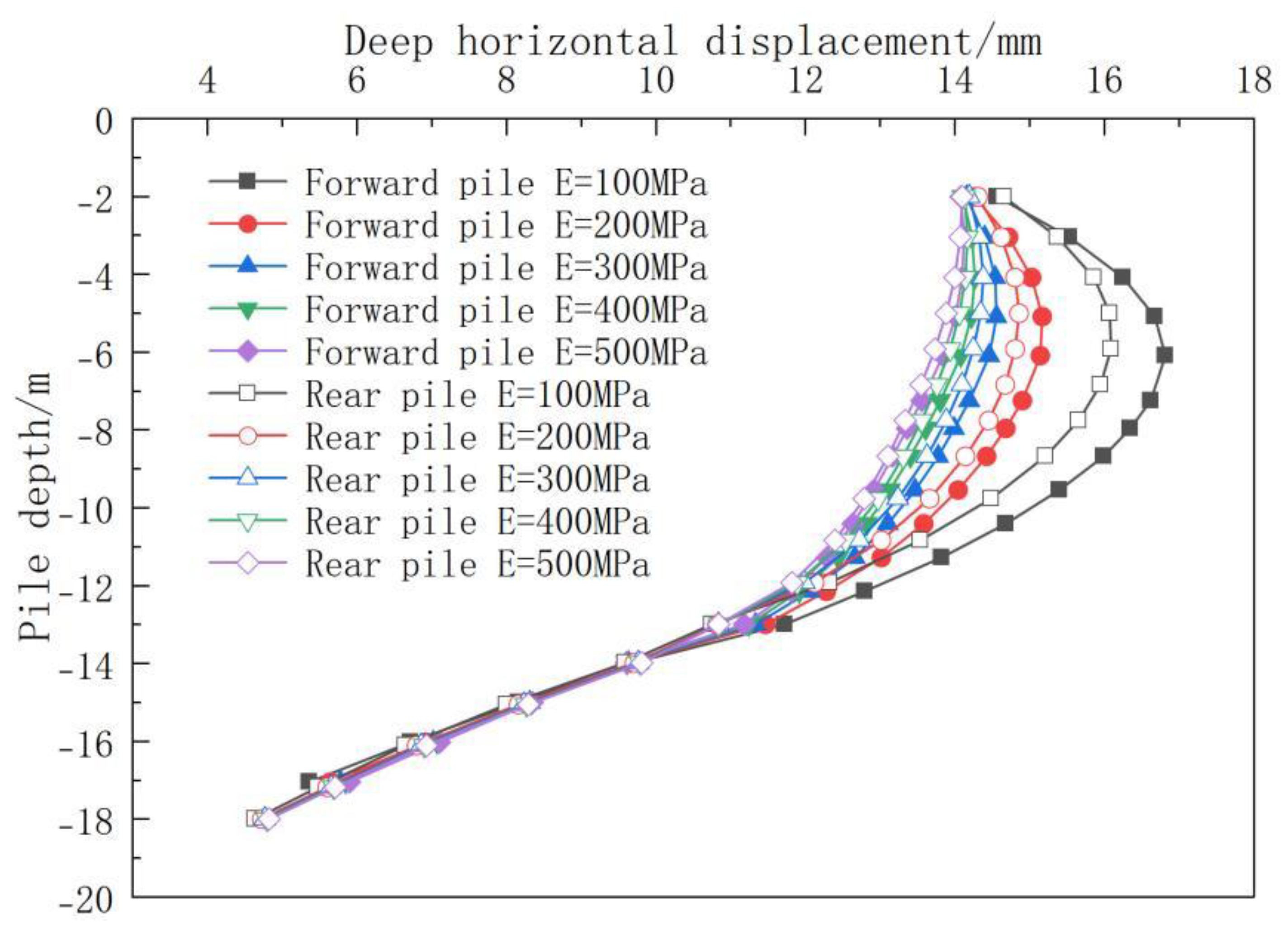
Under full reinforcement conditions, the horizontal displacement of the pile shaft decreases noticeably as the elastic modulus of the reinforced body increases. Numerical calculations demonstrate a substantial decrease in displacement reduction amplitude when the elastic modulus exceeds 300 MPa, as illustrated in Figure 27. In comparison to vertical reinforcement conditions, improved displacement coordination is observed between the front and rear rows of piles under full reinforcement. This enhancement is attributed to the optimized pile–soil collaborative deformation mechanism established post-reinforcement. This mechanism leads to a more balanced soil constraint on the front and rear rows of piles, consequently bolstering the overall stability of the support system.

5.4.2. Influence of Elastic Modulus on the Bending Moment of the Pile Shaft

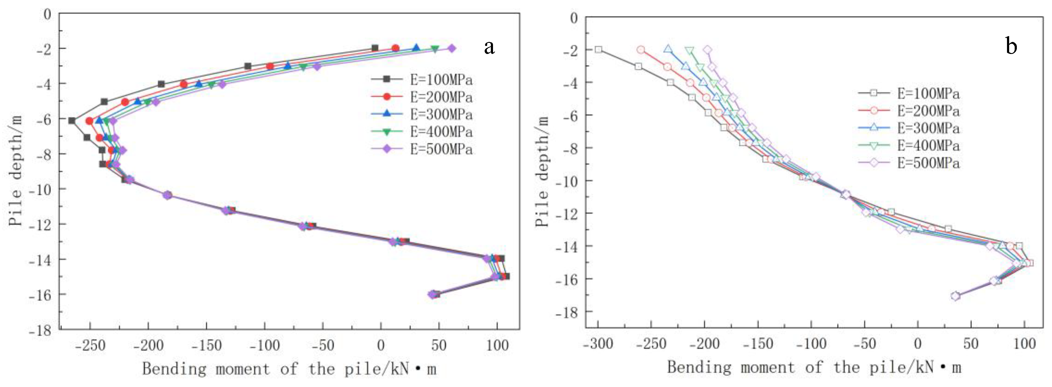
Figure 28 illustrates that under vertical reinforcement, the bending moment of the pile body decreases monotonically with an increase in elastic modulus, albeit with diminishing returns. Notably, when the modulus exceeds 300 MPa, the bending moment significantly decreases. Specifically, the front inclined pile exhibits “shallow accumulation and deep inversion” characteristics, with a negative moment peak near the excavation surface (−6 m) due to the pile’s embedding effect and inclination angle amplification, and a positive moment peak near the pile end (−16 m) due to reverse bending. Conversely, the rear straight pile shows “jacking and bottom tilting” characteristics, with the maximum negative moment resulting from the front pile’s thrust and a positive moment peak near the pile end (−16 m). A neutral plane at 3/4 of the pile length (−13 m) facilitates load transfer. This interaction mechanism enables the vertical reinforcement system to effectively coordinate the pile body’s force distribution.
Under the full reinforcement condition, the soil between inclined and vertical piles forms a rigid integral frame structure, facilitating collaborative force-bearing. The calculation nephogram is depicted in Figure 29. Studies indicate that the bending moment distribution in the pile body demonstrates distinct characteristics, with significant bending moment mutations observed at the termination of the reinforcement depth in both the front and rear rows of piles. Furthermore, the rise in the elastic modulus of the reinforced soil leads to a notable increase in the peak mutation at the junction, primarily due to the heightened impact of the stiffness differential between the reinforced and non-reinforced regions. Specifically, the initial row of inclined piles induces a sharp surge in the reverse bending moment peak in proximity to the excavation surface (−6 m). This phenomenon is underpinned by the alteration of stress transfer pathways facilitated by the lateral resistance system established by the high-stiffness soil and inclined piles, thereby enabling lateral load dispersion. The load-bearing behavior of the rear row of vertical piles is characterized as follows: The bending moment at the pile’s apex exhibits a declining trajectory with the escalation of the reinforced soil’s modulus, maintaining relative stability within the reinforcement span of −2 m to −10 m, with only a marginal decrease. This observation corroborates the reinforcing impact of heightened soil stiffness on the pile body’s restraint, as depicted in Figure 30.

5.5. Sensitivity Analysis of Elastic Modulus

Based on the calculation results presented earlier, the sensitivity coefficients of the reinforcement’s elastic modulus to the displacement and bending moment of the front-inclined and rear-straight double-row piles are shown in Figure 31.
The elastic modulus responds very poorly to pile displacement and bending moment (absolute value is less than 0.3), and the moment response of the rear straight pile is more sensitive to variations of elastic modulus, whereas the displacement response of the front inclined pile is least sensitive. As the elastic modulus increases from 100 to 500, the absolute values of moment sensitivity coefficients for the front inclined pile and rear straight pile decrease gradually. If the elastic modulus of the reinforcement body between piles exceeds 200 MPa, it increases cement content by 12% per 100 MPa, but it is difficult to further reduce the displacement of the pile body.

6. Conclusions

The foundation pit project of the Xiantao Citizen Service Center serves as the basis for our study. By integrating on-site monitoring with numerical simulation, we investigate soil reinforcement between piles in a double-row pile support system with an inclined front and a straight back. Our analysis reveals critical thresholds for the depth of reinforcement and the elastic modulus of the additional solid material. The findings indicate:
  • The displacement distribution of double-row piles, comprising inclined front-row piles and vertical rear-row piles, demonstrates a characteristic deformation resembling an “inward convex drum shape.” Greater inclination angles of the front-row piles enhance the structural deformation control capacity, leading to a pile displacement curve that closely aligns with the pile-brace supporting form’s displacement characteristics.
  • In the supporting system of double-row piles comprising inclined front piles and vertical rear piles, the soil reinforcement between the piles predominantly controls the overall displacement of the pile body (contribution rate: 39.3%). Conversely, the capping beam at the pile top exerts a more pronounced constraint on the displacement at the pile top (contribution rate: 75.4%). In the event of simultaneous failure of both mechanisms, there is a sharp 50% decrease in lateral resistance, leading to a shift in displacement pattern from the previous “inward convex” distribution resulting from coordinated force-bearing to a “cantilever” distribution under single-pile bearing. This transition underscores the essential nature of the dual constraint mechanism.
  • The depth of reinforcement significantly influences the displacement and bending moment of supporting piles. Vertical reinforcement leads to a decrease in both displacement and bending moment as the reinforcement depth increases. Specifically, at a depth equal to the pile length, displacement decreases by 7.0–11.5%. Moreover, for h/H ≥ 1, the bending moment of rear-row piles surpasses that of front-row piles. Under full reinforcement, displacement exhibits a three-stage pattern of “decrease–increase–re-decrease.” The optimal range for controlling displacement is between 0.75 and 1 times the pile length, resulting in a reduction of 30–35%. The bending moment experiences its maximum reduction (53–61%) when h/H = 1–1.5. Notably, the cost-effectiveness of ultra-deep reinforcement (>1.5 times the excavation depth) diminishes significantly. Increasing the elastic modulus of soil reinforcement between piles can effectively reduce the displacement and bending moment of supporting piles. However, the benefits exhibit diminishing returns, with a weakening effect observed beyond 300 MPa. In vertical reinforcement scenarios, front-row piles typically experience 15–20% greater displacement compared to rear-row piles. While full reinforcement improves coordination and overall stability, it amplifies the peak bending moment within the stiffness mutation zone.
  • The sensitivity of reinforcement depth to pile displacement and bending moment is significantly higher than that of elastic modulus, and the sensitivity strength under full reinforcement conditions is generally greater than that under semi-reinforcement conditions.
  • In practical engineering applications, optimizing the reinforcement depth of the soil between piles is essential. The optimal reinforcement depth is typically established at 1.0 to 1.5 times the excavation depth. For foundation pit projects sensitive to the surrounding environment, full-depth reinforcement is recommended, as it more effectively controls deformation in the vicinity. The elastic modulus of the added solid should be set between 200 and 300 MPa. This range facilitates a balance among displacement control, engineering economy, and risk management within the stiffness mutation zone.
  • The research presented in this paper on the parameters of soil reinforcement between piles has been initially completed. However, continuous monitoring of similar projects is necessary to assess potential failure risks and to verify the analysis results discussed herein.

Author Contributions

Z.W.: writing—original draft, writing—review and editing, and software; Z.W. was responsible for the design of research methods, data analysis, and the writing of the initial draft of the paper. J.C.: resources and writing—review and editing; J.C. participated in the review and revision of the paper and provided research funds. P.W.: writing—review and editing; P.W. participated in the design of research methods and the revision of the paper. X.Y.: supervision; X.Y. participated in the review and revision of the paper. Y.X.: supervision, Y.X. participated in the review and revision of the paper. All authors have read and agreed to the published version of the manuscript.

Funding

The publishing of this paper is financially supported by the National Natural Science Foundation of China (No. 42572289 and No. 42472375).

Institutional Review Board Statement

Not applicable.

Informed Consent Statement

Not applicable.

Data Availability Statement

The original contributions presented in the study are included in the article, further inquiries can be directed to the corresponding author.

Conflicts of Interest

Author Yangqing Xu was employed by the company Wuhan Desgin and Research Institute Company Limited of China Coal Technology and Engineering Group. The remaining authors declare that the research was conducted in the absence of any commercial or financial relation-ships that could be construed as a potential conflict of interest.

Nomenclature

γ Bulk Density (kN/m3) f 13 Shear yield function
CCohesion (kPa) f c Compression yield functions
ϕ Internal Friction Angle (°) f t Tensile yield function
ψ Dilatancy angle (°) p c Preconsolidation pressure (kPa)
nPorosity p Average principal stress (kPa)
E 50 r e f Reference secant stiffness in standard hydraulic triaxial test (kPa) p t Tensile strength (kPa)
E o e d r e f Reference tangent stiffness for consolidated loading (kPa) γ p Plastic shear strain
E u r r e f Reference unloading/reloading stiffness (kPa) q a Asymptotic deviation stress
mPower of Stress Level Dependency q f Ultimate deviation stress
K 0 Coefficient of Static Earth Pressure g 13 Shear plastic potential function
R f Failure ratio g c Compression plastic potential function
vPoisson’s ratio g t Stretching plastic potential function
ϕ c s Critical friction angle (°) ϕ m Mobilized friction angle (°)
p c r e f Reference preconsolidation pressure (kPa) Δ ε v p Plastic volumetric strain

References

  1. Zheng, G. Method and application of deformation control of excavations in soft ground. Chin. J. Geotech. Eng. 2022, 44, 1–36. [Google Scholar]
  2. Huang, J.; Liu, J.; Guo, K.; Wu, C.; Yang, S.; Luo, M.; Lu, Y. Numerical Simulation Study on the Impact of Deep Foundation Pit Excavation on Adjacent Rail Transit Structures—A Case Study. Buildings 2024, 14, 1853. [Google Scholar] [CrossRef]
  3. Ge, C.; Yang, M.; Li, P.; Zhang, M.; Zhang, Z. Performance and environmental impacts of deep foundation excavation in soft soils: A field and modeling-based case study in Nanjing, China. Undergr. Space 2024, 18, 218–238. [Google Scholar] [CrossRef]
  4. Liu, R.; Sun, H.; Qin, J.; Zheng, Z. A multi-geophysical approach to assess potential sinkholes in an urban area. Eng. Geol. 2023, 318, 107100. [Google Scholar] [CrossRef]
  5. Kong, H.; Dong, M.; Cao, X.; Lin, S.; Zhao, S.; Zheng, H. Global analysis approach of stability of deep foundation pit slopes reinforced by underground diaphragm walls and prestressed anchor cables. Comput. Geotech. 2023, 163, 105744. [Google Scholar] [CrossRef]
  6. He, B.; Lin, B.; Li, H.; Zhu, S. Suggested method of utilizing soil arching for optimizing the design of strutted excavations. Tunn. Undergr. Space Technol. 2024, 143, 105450. [Google Scholar] [CrossRef]
  7. Wang, J.H.; Xu, Z.H.; Wang, W.D. Wall and Ground Movements due to Deep Excavations in Shanghai Soft Soils. J. Geotech. Geoenviron. Eng. 2010, 136, 985–994. [Google Scholar] [CrossRef]
  8. Yang, J.; Kong, D. Deformation of deep and large foundation pit in soft soil of Fuzhou Subway. Arab. J. Geosci. 2020, 13, 36. [Google Scholar] [CrossRef]
  9. Zhou, N.; Vermeer, P.A.; Lou, R.; Tang, Y.; Jiang, S. Numerical simulation of deep foundation pit dewatering and optimization of controlling land subsidence. Eng. Geol. 2010, 114, 251–260. [Google Scholar] [CrossRef]
  10. Guo, C.C.; Zhu, C.X. Excavation and Support Analysis of Prefabricated Recyclable Double-Row Pile Supporting Structure. J. Zhengzhou Univ. (Eng. Sci.) 2022, 43, 78–83. [Google Scholar]
  11. Ou, X.D.; Lu, Z.F.; Jiang, J.; Luo, F.Z.; Liang, Y.H. Deformation Characteristics of Double-row Pile in Deep Foundation Pit with Water-rich Circular Gravel Layer. Sci. Technol. Eng. 2021, 21, 5484–5490. [Google Scholar]
  12. Zhang, L.; Ou, Q.; Zhu, X.R. Analysis on Forced Deformation of Double Row Piles Considering Pile-pile Interaction in Layered Foundation. J. Hunan Univ. (Nat. Sci.) 2020, 47, 120–126. [Google Scholar]
  13. Lu, Q.X. Research on deformation control of double-row piles near metro deep foundation pit with deep silty sand layer. Build. Struct. 2022, 52, 2423–2427. [Google Scholar]
  14. Zhao, S.F.; Huang, G.L.; Ma, S.Q.; Zhou, W.Y.; Zhang, X. Application of precast concrete pipe piles in a deep excavation project. Chin. J. Geotech. Eng. 2014, 36, 91–96. [Google Scholar]
  15. Ye, J.; He, X. Evaluation of flexural stiffness on mechanical property of dual row retaining pile wall. Mech. Adv. Mater. Struct. 2022, 29, 963–974. [Google Scholar] [CrossRef]
  16. Wang, R.; Yang, H.; Ni, P.; Zhao, C.; Guo, C.; Ma, H.; Dong, P.; Liang, H.; Tang, M. Model test and numerical simulation of a new prefabricated double-row piles retaining system in silty clay ground. Undergr. Space 2023, 13, 262–280. [Google Scholar] [CrossRef]
  17. Huang, K.Y.; Liang, Z.R.; Wei, X. Application and analysis of double-row constant thickness steel cement-soil walls on a large-scale deep excavation. Build. Struct. 2023, 53, 2902–2907. [Google Scholar]
  18. Lan, B.; Wang, Y.; Wang, W. Review of the Double-Row Pile Supporting Structure and Its Force and Deformation Characteristics. Appl. Sci. 2023, 13, 7715. [Google Scholar] [CrossRef]
  19. Wang, Z.; Zhou, J. Three-dimensional numerical simulation and earth pressure analysis on double-row piles with consideration of spatial effects. J. Zhejiang Univ.-Sci. A 2011, 12, 758–770. [Google Scholar] [CrossRef]
  20. Du, P.C.; Peng, X.; Ma, L.; Li, M.Y.; Xu, H.R.; Yang, K.X. Research on spatial effect of double-row piles supporting structure for deep foundation pit. Build. Struct. 2021, 51, 2038–2043. [Google Scholar]
  21. Ou, X.D.; Tan, Z.J.; Luo, F.Z.; Jiang, J.; Liang, Y.H. Numerical Analysis of Influence of Design Parameters on the Double-row Pile Support Structure of Deep Foundation Pit. Sci. Technol. Eng. 2021, 21, 2873–2878. [Google Scholar]
  22. Gao, Y.; Sun, H.K.; Liu, R.C. Slope deformation and parameters sensitivity in the design of double-row supporting piles. J. Shandong Univ. (Eng. Sci.) 2019, 49, 86–94. [Google Scholar]
  23. Hu, X.; Liu, D.; Niu, L.; Liu, C.; Wang, X.; Fu, R. Development of soil–pile interactions and failure mechanisms in a pile-reinforced landslide. Eng. Geol. 2021, 294, 106389. [Google Scholar] [CrossRef]
  24. Yu, F.; Xie, Z.; Duan, N.; Liu, N.; Shan, H. Performance of double-row piles retaining excavation beneath existing underground space. Int. J. Phys. Model. Geotech. 2019, 19, 167–180. [Google Scholar] [CrossRef]
  25. Dong, B.; Wang, Q.; Ma, F.; Zhang, C.; Zou, L. Calculation Theory of Counterweight Double-Row Pile Support for Deep Foundation Pit in Reclamation Area and Influence Analysis of Core Pile Parameters. Sustainability 2023, 15, 6184. [Google Scholar] [CrossRef]
  26. Wang, X.Q.; Liao, Z.Y.; Zheng, T.Y.; Zhu, D.L. Model test study on bearing characteristics of double-row piles based on reinforcement effect of soil around piles. J. Civ. Environ. Eng. 2021, 43, 19–25. [Google Scholar]
  27. Seo, M.; Im, J.; Kim, C.; Yoo, J. Study on the applicability of a retaining wall using batter piles in clay. Can. Geotech. J. 2016, 53, 1195–1212. [Google Scholar] [CrossRef]
  28. Zheng, G.; He, X.P.; Zhou, H.Z.; Wang, E.Y.; Yang, S.F.; Wei, J.H. Working mechanism of inclined-vertical retaining piles in excavations. Chin. J. Geotech. Eng. 2019, 41, 97–100. [Google Scholar]
  29. Fan, P.C.; Hu, Z.W. Simulation of Single-row Oblique Straight Alternate Piles in Soft Soil Foundation Pit Support. J. Water Resour. Archit. Eng. 2018, 16, 134–137. [Google Scholar]
  30. Wang, E.Y.; Zhou, H.Z.; Zheng, G.; He, X.P.; Yang, S.F.; Wei, J.H. Numerical analyses of deformation of inclined pile-retained excavations. Chin. J. Geotech. Eng. 2019, 41, 73–76. [Google Scholar]
  31. Diao, Y.; Su, Y.M.; Zheng, G. Numerical study on oblique-straight alternate piles for active support of excavations. Chin. J. Geotech. Eng. 2019, 41, 161–164. [Google Scholar]
  32. Xu, Y.; Zheng, G.; Lu, P. Behaviors of double-row contiguous retaining piles with raking front-row piles under horizontal loads. Chin. J. Geotech. Eng. 2010, 32, 93–98. [Google Scholar]
  33. Tian, Y.; Yu, D.H.; Lai, G.L.; Chen, G.; Song, Z.; Liu, Y. Calculation and monitoring analysis of inclined precast pile foundation pit support in soft soil area of Hanjiang River terrace. Build. Sci. 2023, 39, 168–174. [Google Scholar]
  34. Xiao, H.N.; Cao, W.P.; Zhao, M.; Luo, L.P.; Xi, M.Y. Numerical Analysis on Force and Deformation of Composite Piles for Loess Foundation Pit Inclination. J. Wuhan Univ. Technol. (Transp. Sci. Eng.) 2024, 48, 1199–1204. [Google Scholar]
  35. Zheng, G.; Wang, Y.P.; Cheng, X.S.; Yu, D.H.; Huang, X.C.; Li, X.H. Field Experiment and Working Mechanism of Foundation Pit Excavation Retained by Front-row Inclined Double Row Piles in Soft Soil Area. J. Yangtze River Sci. Res. Inst. 2024, 41, 98–105, 113. [Google Scholar]
  36. Qiu, H.; Zhou, Y.; Ayasrah, M.M. Impact Study of Deep Foundations Construction of Inclined and Straight Combined Support Piles on Adjacent Pile Foundations. Appl. Sci. 2023, 13, 1810. [Google Scholar] [CrossRef]
  37. Wu, Y.; Ye, J.; Ge, H.; Liu, G.; Liu, H. Numerical investigation of dual-row batter pile wall in deep excavation. Mech. Adv. Mater. Struct. 2022, 29, 5793–5807. [Google Scholar] [CrossRef]
  38. Teo, P.L.; Wong, K.S. Application of the Hardening Soil model in deep excavation analysis. IES J. Part A Civ. Struct. Eng. 2012, 5, 152–165. [Google Scholar] [CrossRef]
  39. Zhao, Y.; Lu, Z.; Liu, J.; Zhang, J.; Yao, H. Influence of different infill materials on the performance of geocell-reinforced cohesive soil beds. Sci. Rep. 2023, 13, 12330. [Google Scholar] [CrossRef]
  40. Schanz, T.; Vermeer, P.A.; Bonnier, P.G. The hardening soil model: Formulation and verification. Beyond Comput. Geotech. 1999, 11, 281–296. [Google Scholar]
  41. Liu, H.; Li, K.; Wang, J.; Cheng, C. Numerical Simulation of Deep Foundation Pit Construction under Complex Site Conditions. Adv. Civ. Eng. 2021, 2021, 6669466. [Google Scholar] [CrossRef]
  42. Goh, A.T.C.; Zhang, F.; Zhang, W.; Zhang, Y.; Liu, H. A simple estimation model for 3D braced excavation wall deflection. Comput. Geotech. 2017, 83, 106–113. [Google Scholar] [CrossRef]
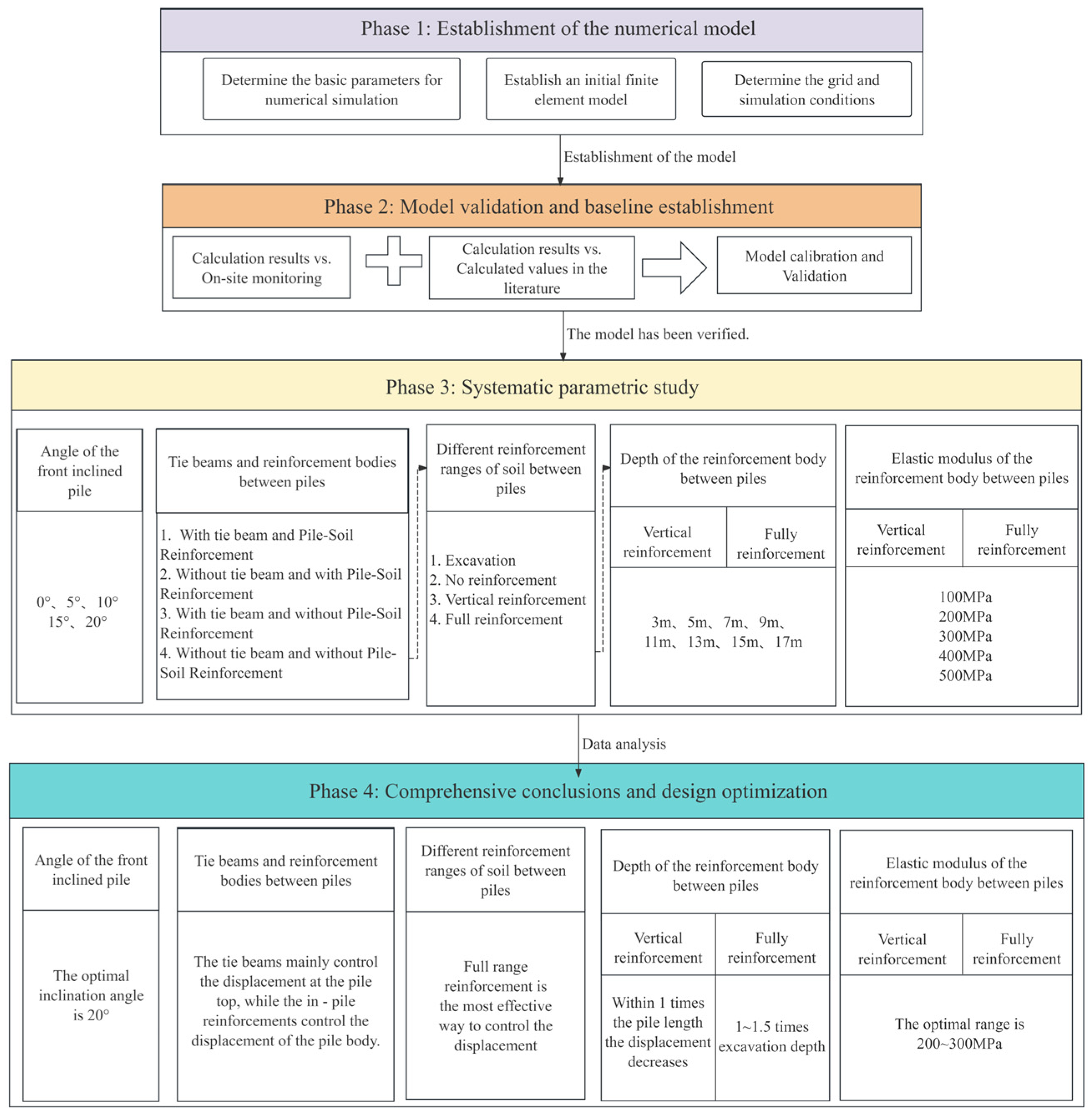
Figure 1. Technology roadmap.
Applsci 15 12443 g001
Figure 2. Force mechanism diagram of double-row piles with front-inclined and rear-vertical arrangement.
Applsci 15 12443 g002
Figure 3. General situation of support plane layout and foundation pit excavation. (a) Plan of support structure (b) Plan of foundation pit excavation to base level (c) Plan of excavation to base level for the area with front inclined and rear straight double-row piles (d) Close-up view of front inclined and rear straight double-row piles.
Applsci 15 12443 g003
Figure 4. Typical cross-sectional view of foundation pit support.
Applsci 15 12443 g004
Figure 5. Establishment of numerical modeling.
Applsci 15 12443 g005
Figure 6. Numerical analysis flow chart.
Applsci 15 12443 g006
Figure 7. Comparison diagrams of calculation cloud maps and pile displacement under different mesh sizes: (a) grid size 2 m, (b) grid size 1 m, and (c) grid size 0.5 m.
Applsci 15 12443 g007
Figure 8. Comparison diagram of maximum displacement under different mesh sizes.
Applsci 15 12443 g008
Figure 9. Percentage diagram of pile displacement variation with mesh size: (a) front pile, and (b) rear pile.
Applsci 15 12443 g009
Figure 10. Comparison diagram of numerical simulation calculation values and on-site monitoring values (a) Three-dimensional finite element displacement calculation nephogram in this paper. (b) Comparison of pile displacement curves, (c) earth pressure comparison diagram, and (d) pile bending moment comparison diagram.
Applsci 15 12443 g010
Figure 11. Error analysis diagram of calculated values and monitored values: (a) error comparison of front inclined piles, (b) error comparison of rear vertical piles, (c) correlation coefficient diagram of inclined front pile displacement, and (d) correlation coefficient diagram of vertical rear pile displacement.
Applsci 15 12443 g011
Figure 12. The curve of displacement varies with excavation depth: (a) Vertical double-row piles, and (b) double-row piles with a front inclination angle of 15°.
Applsci 15 12443 g012
Figure 13. Schematic diagrams of support structures with different inclination angles and pile displacement curves. (a) Schematic diagram of the support structure. (b) Curve of pile displacement varying with inclination angle.
Applsci 15 12443 g013
Figure 14. The maximum displacement of the support system under different inclination angles.
Applsci 15 12443 g014
Figure 15. Support schematic and calculation cloud diagrams of different combination forms of tie beam and pile–soil reinforcement structure: (a) tie beam and pile–soil reinforcement, (b) without tie beam and with pile–soil reinforcement, (c) with tie beam and without pile–soil reinforcement, and (d) without tie beam and without pile–soil reinforcement.
Applsci 15 12443 g015
Figure 16. Pile displacement curves under different combination forms of tie beam and pile–soil reinforcement.
Applsci 15 12443 g016
Figure 17. Maximum displacement under different combination forms of tie beam and pile–soil reinforcement.
Applsci 15 12443 g017
Figure 18. Control the deformation contribution rate of the supporting structure. (a) Pile–soil reinforcement, and (b) tie beam.
Applsci 15 12443 g018
Figure 19. Support schematics and calculation cloud diagrams of soil reinforcement between piles in different ranges: (a) excavation, (b) no reinforcement, (c) vertical reinforcement, and (d) full reinforcement.
Applsci 15 12443 g019
Figure 20. Pile displacement curves under different reinforcement ranges.
Applsci 15 12443 g020
Figure 21. Under vertical soil reinforcement between piles, max displacement of retaining structure varies with reinforcement depth.
Applsci 15 12443 g021
Figure 22. Under full reinforcement of soil between piles, max displacement of retaining structure varies with reinforcement depth.
Applsci 15 12443 g022
Figure 23. Under vertical reinforcement of soil between piles, max bending moment of retaining structure varies with reinforcement depth.
Applsci 15 12443 g023
Figure 24. Under full reinforcement of soil between piles, max bending moment of retaining structure varies with reinforcement depth.
Applsci 15 12443 g024
Figure 25. Sensitivity analysis of support pile to reinforcement depth: (a) vertical reinforced inclined front pile, (b) vertical reinforced vertical rear pile, (c) full reinforced inclined front pile, and (d) full reinforced vertical rear pile.
Applsci 15 12443 g025
Figure 26. Under vertical reinforcement of soil between piles, pile displacement varies with the elastic modulus of reinforced soil.
Applsci 15 12443 g026
Figure 27. Under full reinforcement of soil between piles, pile displacement varies with the elastic modulus of reinforced soil.
Applsci 15 12443 g027
Figure 28. Under vertical reinforcement of soil between piles, pile bending moment varies with the elastic modulus of reinforced soil: (a) front-inclined pile and (b) rear vertical pile.
Applsci 15 12443 g028
Figure 29. Calculation contours of the pile bending moment under full reinforcement of inter-pile soil: (a) 100 MPa, (b) 200 MPa, (c) 300 MPa, (d) 400 MPa, and (e) 500 MPa.
Applsci 15 12443 g029
Figure 30. Under full reinforcement of soil between piles, the pile bending moment varies with the elastic modulus of reinforced soil: (a) front-inclined pile and (b) rear vertical pile.
Applsci 15 12443 g030
Figure 31. Sensitivity analysis of support piles to elastic modulus of reinforcement bodies: (a) vertical reinforced inclined front pile, (b) vertical reinforced vertical rear pile, (c) full reinforced inclined front pile, and (d) full reinforced vertical rear pile.
Applsci 15 12443 g031
Table 1. Parameters of the HS model.
Layer NameDepth of Stratum/mvγ/kN/m3 E 50 r e f /MPa E o e d r e f /MPa E u r r e f /MPa C c u /kPa φ c u
② Silty clay interbedded with silt (Q4ml)1.480.217.94.84.813.44149
③ Sludgy soil (Q4l)2.600.216.72.92.98.12104
④ Clays (Q4al)4.600.218.46.26.217.362312
⑤ Silty clay (Q4al+pl)5.300.218.05.05.014.0147
⑥ Silty clay interbedded with silty sand (Q4al+pl)3.200.218.210.510.547.251810
⑦ Silty sand (Q4al+pl)9.900.219.015.515.577.5131
solid between piles11.00/22.0/////
Table 2. Structural finite element parameters.
Structure NameUnit TypeCross-Sectional Dimensionγ/kN/m3E/GPav
PRC pileBeamOuter diameter 0.6 m, wall thickness 0.11 m25800.2
Crown beamBeamWidth 1 m, height 0.8 m25300.2
Concrete spraying surfaceBoardThickness 0.1 m23200.2
Disclaimer/Publisher’s Note: The statements, opinions and data contained in all publications are solely those of the individual author(s) and contributor(s) and not of MDPI and/or the editor(s). MDPI and/or the editor(s) disclaim responsibility for any injury to people or property resulting from any ideas, methods, instructions or products referred to in the content.