Article

Thermal–Hydraulic–Mechanical Coupling Effects and Stability Analysis of Surrounding Rock in Ultra-Deep Mine Shaft Excavation

1
China Coal Construction Group Limited Corporation, Beijing 102218, China
2
State Key Laboratory of Intelligent Construction and Healthy Operation and Maintenance of Deep Underground Engineering, China University of Mining and Technology, Xuzhou 221116, China
3
Beijing China Coal Mine Engineering Company Limited, Beijing 100013, China
*
Authors to whom correspondence should be addressed.
Appl. Sci. 2025, 15(23), 12433; https://doi.org/10.3390/app152312433
Submission received: 16 September 2025 / Revised: 17 October 2025 / Accepted: 19 November 2025 / Published: 24 November 2025
(This article belongs to the Section Earth Sciences)

Abstract

This study addresses the stability and deformation control of the Xiling auxiliary shaft in the Sanshandao Gold Mine during excavation, under the complex geological conditions of high in situ stress, high pore pressure, and elevated geothermal gradients. A thermal–hydraulic–mechanical (THM) coupling numerical model is developed to investigate the stress distribution, deformation mechanisms, and long-term stability of the surrounding rock under multi-physical interactions. Meanwhile, the influence of excavation rate on rock stability is analyzed. The results indicate that excavation induces significant stress redistribution, with stress concentrations in high-elastic-modulus strata, where the maximum compressive and tensile stresses reach 15.9 MPa and 14.1 MPa, respectively. The maximum displacement occurs in low-stiffness rock layers (around 1400 m depth), with a total magnitude of 1139 mm, primarily resulting from unloading relaxation, pore pressure reduction, and thermal contraction. Excavation rate strongly affects the temporal evolution of deformation: faster excavation leads to greater instantaneous displacements, whereas slower excavation suppresses displacement due to the sustained influence of thermal contraction. Based on these findings, particular attention should be paid to the low-stiffness strata near 1400 m depth during the construction of the Xiling auxiliary shaft. A combined support system consisting of high-prestress rock bolts, lining, and grouting is recommended for deformation-concentrated zones, while excavation rates should be optimized to balance efficiency and safety. Furthermore, long-term monitoring of temperature, pore pressure, and displacement is essential to achieve dynamic risk control. These results provide valuable theoretical and engineering insights for the safe construction and stability management of deep mine shafts.

1. Introduction

With the progressive depletion of shallow mineral resources, the exploitation of deep mineral resources has become an inevitable choice to ensure national resource security [1,2,3]. At present, many shafts deeper than 1500 m have been constructed in China, such as the main and auxiliary shafts of the Sishanling Iron Mine (1505 m and 1503.9 m), the #3 shaft of the Huize lead–zinc mine in Yunnan Province (1526 m), and the main shaft of the Xincheng Gold Mine in the Shandong Gold Group (1527 m) [2,4,5]. These projects demonstrate the engineering feasibility of deep mining. However, deep mining is confronted with far more complex geological and geotechnical conditions [6]. Deep rock masses are subjected to high in situ stresses, high pore pressures, and elevated temperatures [7]. Excavation activities severely disturb the original equilibrium, inducing the redistribution and strong coupling of the stress, seepage, and temperature fields (thermal–hydraulic–mechanical, THM) [8,9,10], which, in turn, significantly increase the risks of large rock deformations, water inrush, and other severe engineering hazards. Such incidents may result in catastrophic casualties and economic losses, thereby posing a major challenge to the safe and efficient exploitation of deep mineral resources. Consequently, it is of great theoretical and practical importance to investigate the THM coupling effects and stability control mechanisms during deep shaft excavation.
In recent years, numerous researchers and experts in shaft construction and rock mechanics have conducted extensive studies on the failure and instability characteristics of surrounding rock in deep shaft excavation projects. Hou et al. [4] investigated the stability of a kilometer-deep shaft at Sanshandao Gold Mine under the combined effects of high in situ stress, heterogeneous strata, and fault structures. Their study revealed that passing through different lithologies or fault zones significantly enlarges the extent of surrounding rock damage. Qin et al. [11] focused on the Xiling auxiliary shaft at Sanshandao Gold Mine, analyzing the rockburst mechanisms in detail and developing a novel rockburst prediction model based on variational and functional theories. This model successfully identified a high-risk zone at 1561 m depth, upon which the researchers proposed corresponding rockburst prevention and support strategies. Xiao et al. [12] conducted investigations on rock bursts in five ultra-deep gold mines in the Jiaodong Peninsula, analyzing the mechanisms from the perspective of in situ stress. Their results indicated that increased in situ stress is a key factor triggering severe rock burst hazards. In this region, when excavation depth exceeds 1000 m, large area collapse also occurs in some tunnels, demonstrating complex hazard characteristics. Wu et al. [1] used FLAC3D numerical simulation to study the disturbance effects on the main inclined shaft caused by the excavation of electromechanical drifts in Yuxi Coal Mine, Jincheng, China. By analyzing the stress and deformation of the surrounding rock before and after excavation, they found that excavation significantly alters the stress distribution around the main shaft and nearly doubles the floor deformation. Li et al. [2] systematically studied the stability of the newly constructed main shaft at Xincheng Gold Mine in Laizhou, China, from the perspectives of in situ stress measurement, surrounding rock disturbance, and deformation and failure characteristics, proposing a stability control method suitable for large-section ultra-deep shafts. Shu et al. [8] addressed the lining stability of deep shafts in weakly cemented, water-rich strata in western China under stress–seepage coupling, recommending coarse aggregate ultra-high-performance concrete (CA-UHPC) as a lining material. By performing stress–seepage coupling experiments under different confining and pore pressure conditions, they systematically investigated the deformation behavior, strength characteristics, and permeability evolution of the lining material. Lu et al. [9] quantitatively analyzed the spatiotemporal response of tunnels under active cooling using thermo–mechanical coupling modeling and local safety factor analysis, revealing that continuous cooling can induce critical switches of principal stress direction, resulting in a staged evolution of excavation stability characterized by ‘initial improvement and ensuing degradation’. Wang et al. [7] studied ultra-large-section tunnels in the Qianyingzi Coal Mine, Suzhou, China, analyzing deformation and failure mechanisms under high in situ stress and strong disturbance based on stress distribution, rock strength, and fracture development. They proposed a combined ‘grouting–anchoring–shotcrete’ control strategy suitable for large-section soft-rock tunnels. Wen et al. [13] systematically analyzed typical failure features of deep coal mine tunnels, revealing the distribution of plastic zones and corresponding failure modes under different lateral pressure coefficients. Based on plastic zone distribution, a support design method was proposed and validated against existing support schemes. Hall et al. [14] studied notch failure modes and depths in boreholes at Glencore’s Onaping Depth project, Craig Mine, Ontario, Canada (depth 1150–1915 m). Their results indicated that stress fracturing and erosion are the primary causes of trench deterioration, and their combined action produces a synergistic effect, exacerbating damage. In summary, existing studies mainly focus on single or partially coupled mechanisms of surrounding rock response, with a lack of research on the stability of ultra-deep shafts under the combined effects of high in situ stress, high pore pressure, and elevated temperature. Furthermore, the influence of excavation rate—a critical construction parameter—on the fully coupled THM process has not been systematically revealed.
Against this background and engineering demand, this study takes the Xiling auxiliary shaft of the Sanshandao Gold Mine in Laizhou, Shandong Province, China, as a typical ultra-deep shaft engineering case to investigate the THM coupling mechanisms and stability evolution of the surrounding rock during excavation. The first contribution of this study lies in the establishment of a THM coupling model that fully considers the interactions among stress, fluid flow, and temperature during the excavation of ultra-deep shafts. The second contribution is a stability analysis of the Xiling auxiliary shaft excavation in the Sanshandao Gold Mine based on the THM coupling model. The structure of this article is: A THM fully coupling numerical model is established and validated for reliability. Subsequently, the stress distribution, displacement field, and pore pressure and temperature characteristics of the surrounding rock after shaft excavation are systematically analyzed. The effects of different excavation rates on rock mass deformation and stability are explored, and potential risk zones are identified, with corresponding stability control strategies proposed. The findings provide theoretical reference and practical guidance for the safe construction and risk management of ultra-deep shafts under high in situ stress, high pore pressure, and high-temperature coupled conditions.

2. Engineering Background

2.1. Geographical Location

The Sanshandao Gold Mine, located in Laizhou, Shandong Province, China, is a typical coastal metal mine. Since its commissioning in the 1980s, the mine has been in continuous operation for over three decades and is currently one of the largest rock-hosted gold deposits in China in terms of resource reserves. The mine mainly comprises two major mining areas: the Xishan mining area and the Xinli mining area. The proposed Xiling auxiliary shaft is situated within the Xishan mining area of the Sanshandao Gold Mine, approximately 25 km from Laizhou. It is adjacent to the existing mining area of the Sanshandao Gold Mine to the southwest, and borders the newly constructed Laizhou Port to the east. A highway lies about 3 km south of the auxiliary shaft, while a railway traverses the southern part of the mining area, with Laizhou Station located about 25 km away, providing relatively convenient transportation conditions. Against this background, the geological stability and deformation control issues involved in the excavation of the Xiling auxiliary shaft are not only directly related to the safe construction and subsequent operation of the shaft itself, but also critically influence the safe and efficient development of resources in the entire Sanshandao Gold Mine, the long-term stability of key surrounding infrastructure such as the port, highway, and railway, as well as the safety of local residents’ lives and property. This underscores its significant practical engineering relevance and broad social impact.

2.2. Geological Characteristics

The mining area is located in the northwestern part of the Jiaodong Peninsula, where the nearshore and submarine topography is relatively flat, with three small hills developed near the coast (i.e., Sanshandao). Structurally, the area lies in the western part of the Jiaoliao Uplift within the North China Plate, bounded by the Yishu Fault Zone to the west, the Jiaolai Basin to the south, and the Longkou Depression to the north. The metallogenic geological background of the gold deposit is mainly composed of an ancient metamorphic basement, multi-stage and multi-genetic magmatic activities, and a fault-dominated structural framework, with NE-trending faults playing a controlling role. Faulting is the dominant structural feature in the area, and the main orebodies are hosted within the Sanshandao Fault Zone. The fault zone trends generally NE, with an average strike of 38° in the eastern segment and 58° in the western segment. The area is relatively stable, with no historical records of strong earthquakes, surface subsidence, ground fissures, or debris flow hazards. The weathered zone is relatively thin, and the shaft wall rock is dominated by monzogranite, accounting for 89.7%. The rock mass is generally moderately to highly intact, with localized zones of moderate to strong fracturing. Overall, permeability is weak, making the conditions favorable for engineering construction. The physical and mechanical properties of the rocks are listed in Table 1. In situ stress measurements indicate that at depths of 1000 m, 1500 m, and 1900 m, the maximum principal stresses are 40 MPa, 52 MPa, and 70 MPa, respectively, while the minimum principal stresses are 26 MPa, 35 MPa, and 47 MPa, respectively.
Based on drilling logs, preliminary hydrogeological observations, and pumping test data, the aquifers can be divided into three sections: (1) The first section is the bedrock weathering-fracture aquifer and the overlying structural fracture aquifer, which has developed a drained zone at the top due to mining activities, with a depth range of 0.00–218.50 m. (2) The second section is a bedrock structural fracture aquifer that has become water-bearing due to depressurization from mining, occurring at depths of 218.50–874.03 m. Yellowish-brown water-erosion marks were observed at depths of 317.00–332.00 m, 396.00–399.00 m, 530.00–535.00 m, and 558.00–562.00 m. Geophysical interpretation indicates signs of groundwater inflow, with an aquifer thickness of 27.00 m. In the remaining intervals, drill cores are mostly long-columnar, with flat and closed fracture surfaces, and the rock mass is moderately to highly intact, with good aquitard properties. (3) The third section is the deeper bedrock structural fracture aquifer, less affected by mining, occurring at depths of 874.03–2017.56 m. Geophysical well logging detected signs of groundwater inflow at 999.00–1004.00 m, 1131.00–1137.00 m, 1159.00–1164.00 m, 1442.00–1448.00 m, 1633.00–1638.00 m, and 1720.00–1730.00 m. The aquifer thickness in this section is 37.00 m, while the remaining intervals show moderately to highly intact rock masses with good aquitard performance. The results of pumping tests and predicted permeability coefficients are provided in Table 2.

3. Numerical Model

The Xiling auxiliary shaft of the Sanshandao Gold Mine is located in an environment characterized by high in situ stress, high pore water pressure, and high geothermal gradient. To investigate the coupled relationships among the stress field, seepage field, and temperature field during excavation, as well as the deformation and failure mechanisms of rock under such coupling effects, a thermal–hydraulic–mechanical (THM) coupling model is established in this study. Compared with previous studies on single M field or HM coupling, this study fully considers the coupling interactions between THM, which can better simulate the actual working conditions of ultra-deep wells.

3.1. Governing Equations of the THM Coupling Model

3.1.1. Stress Field

Rock deformation is influenced by in situ stress, pore pressure, and temperature. Excavation is a slow process lasting several days. The rate of load change is 4–5 orders of magnitude slower than the propagation of stress waves. Stress waves have sufficient time to allow the rock mass to reach quasi-static equilibrium at each moment. Therefore, inertia effects can be neglected, and this study uses quasi-static equations to control the stress field. For linear elastic materials, the stress–strain relationship can be expressed by the generalized Hooke’s law [15,16]:
σ i j = 2 G ε i j + 2 G ν 1 2 ν ε k k δ i j α p δ i j K α T T δ i j
where σij is the Cauchy stress tensor; εij is the strain tensor; εkk = ε11 + ε22 + ε33 is the first strain invariant or volumetric strain; ν is the Poisson’s ratio; G = E/(2(1 + ν)) is the shear modulus of rock, and E is the elastic modulus of rock; K = E/(3(1 − 2ν)) is the bulk modulus; δij is the Kronecker sign, when i = j, δij = 1, and when ij, δij = 0; p is the pore pressure; i and j = 1,2,3 for three-dimensional model; T is the temperature of rock; α is the Biot coefficient; αT is the volume thermal expansion coefficient of rock.
The equilibrium equation of the rock is as follows:
σ i j , j + f i = 0
where fi is the unit body force in the ith direction.
The relationship between strain and displacement of rock is as follows:
ε i j = 1 2 u i , j + u j , i
where ui denotes the displacement in the ith direction.
During excavation, the Navier deformation equation of rock under THM coupling can be derived from Equations (1)–(3):
G u i , j j + G 1 2 v u j , j i α p , i K α T T , i + f i = 0

3.1.2. Seepage Field

The fluid flow in rock during excavation obeys the mass conservation law, which can be expressed as [17]:
ρ w ϕ t + ρ w u = ρ w α ε v t
where ρw is the density of water; ϕ is the porosity of rock; εv is the volumetric strain. The term on the right-side of Equation (5) expresses the source/sink term which is induced by the deformation of rock.
Assuming that fluid flow in the rock follows Darcy’s law, the velocity is given by the following:
u = K s ρ w g p ρ w g
where the Ks is the hydraulic conductivity; g is the gravity.

3.1.3. Temperature Field

Heat transfer in water-bearing porous rock consists of two components: heat transfer by the rock matrix and heat transfer by the fluid in the porous medium. The heat transfer by the rock matrix is primarily conductive, and its governing equation is as follows:
1 ϕ ρ s C s T t = 1 ϕ λ s 2 T
Compared with heat transfer by the rock matrix, heat transfer by fluid includes an additional convective heat transfer, which can be expressed as follows:
ϕ ρ w C w T t + ρ w C w u T = ϕ λ w 2 T
where ρs is the density of rock; Cs is the heat capacity of rock; λs is the thermal conductivity of rock. Cw is the specific heat capacity of fluid; λw is the thermal conductivity of fluid.
By adding Equations (8) and (9), the governing equation for the temperature field during excavation can be obtained as follows:
1 ϕ ρ s C s + ϕ ρ w C w T t + ρ C w u T = 1 ϕ λ s + λ w 2 T

3.1.4. Coupling Effects

The coupling interactions among the stress field, seepage field, and temperature field are shown in Figure 1, including [18,19,20]: (1) the influence of the stress field on the seepage field: stress variations lead to changes in porosity and hydraulic conductivity, thereby affecting seepage; (2) the influence of the stress field on the temperature field: matrix deformation alters porosity and consequently heat transfer within the matrix; (3) the influence of the seepage field on the temperature field: fluid flow removes heat from the system in the form of convective heat transfer; (4) the influence of the seepage field on the stress field: variations in pore pressure affect effective stress, thus influencing rock deformation; (5) the influence of the temperature field on the stress field: temperature variations induce thermal expansion and corresponding deformation of the matrix; (6) the influence of the temperature field on the seepage field: temperature affects fluid properties, thereby influencing fluid flow. Among these, the governing equations already account for coupling interactions (2) through (5), while interactions (1) and (6) are described as follows.
For Interaction (1), the variations in rock porosity and permeability in porous media are jointly influenced by in situ stress, pore pressure, and temperature, and evolve dynamically during the excavation process, which can be expressed as follows [21,22]:
ϕ = 1 1 ϕ 0 1 Δ p / K + α T Δ T 1 + ε v
In this study, a simple cubic Kozeny–Carman (KC) grain model is adopted to describe the relationship between permeability and porosity, which is expressed as follows [23,24]:
k = k 0 ϕ ϕ 0 3 1 ϕ 0 1 ϕ 2
where ϕ0 is the initial rock porosity; k0 is the initial rock permeability.
The relationship between permeability and hydraulic conductivity is given as follows:
K s = k ρ w g μ w
For interaction (6), the thermophysical properties of water are jointly affected by both pressure and temperature. However, compared with temperature, the influence of pressure is relatively minor. Therefore, in this study, only the effect of temperature on the thermophysical properties of water is considered. The temperature-dependent expressions for water density (ρw, units in kg/m3), dynamic viscosity (μw, units in Pa·s), constant pressure heat capacity (Cw, units in J/(kg·K)), and thermal conductivity (λw, units in W/(m·K)) can be written as [18,25]:
ρ w = 1000 1 T 3.98 2 508,929.2 T + 288.9414 T + 68.12963 , 0 T 20 ° C 996.9 1 3.17 10 4 T 25 2.56 10 6 T 25 2 , 20 ° C < T 100 ° C
μ w = 10 3 1 + 0.015512 T 293.15 1.572 , 0 T 100 ° C
C w = 12,010.1471 80.4072879 T + 273.15 + 0.309866854 T + 273.15 2 5.38186884 10 4 T + 273.15 3 + 3.62536437 10 7 T + 273.15 4 , 0 T 100 ° C
λ w = 10 3 922.47 + 2839.5 T + 273.15 273.15 1800.7 T + 273.15 273.15 2 + 525.77 T + 273.15 273.15 3 73.44 T + 273.15 273.15 4 , 0 T 100 ° C

3.2. Model Validation

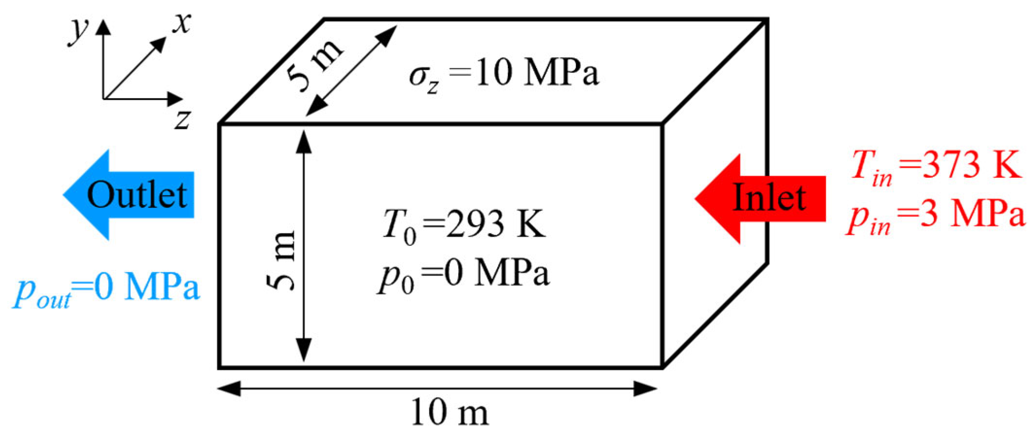
To evaluate the reliability of the THM coupling model developed in this study, a THM coupling problem is verified using a cuboid domain with dimensions of 5 m × 5 m × 10 m, as shown in Figure 2 [24,26]. This validation model [24] also involves the thermal-hydraulic-mechanical (THM) coupling process, and the governing equations of the physical fields are consistent with those in this study. Therefore, we selected this model to compare our computed results with those of others, in order to verify the correctness of the THM coupling model in this study. The initial conditions are set as a temperature of 293 K and a pressure of 0 MPa. The right side is defined as the inlet, and the left side as the outlet. An injection pressure of 3 MPa and an injection fluid temperature of 373 K are applied. For the external loading conditions, a compressive stress of σz = 10 MPa is applied along the z-direction, while the normal displacements on the other boundaries are constrained using roller supports. The outlet boundary pressure is set to 0 MPa, and the temperature gradient is zero along the outflow direction. The remaining boundaries are specified as thermally insulated and impermeable. The parameters used in the calculation are listed in Table 3 [26].
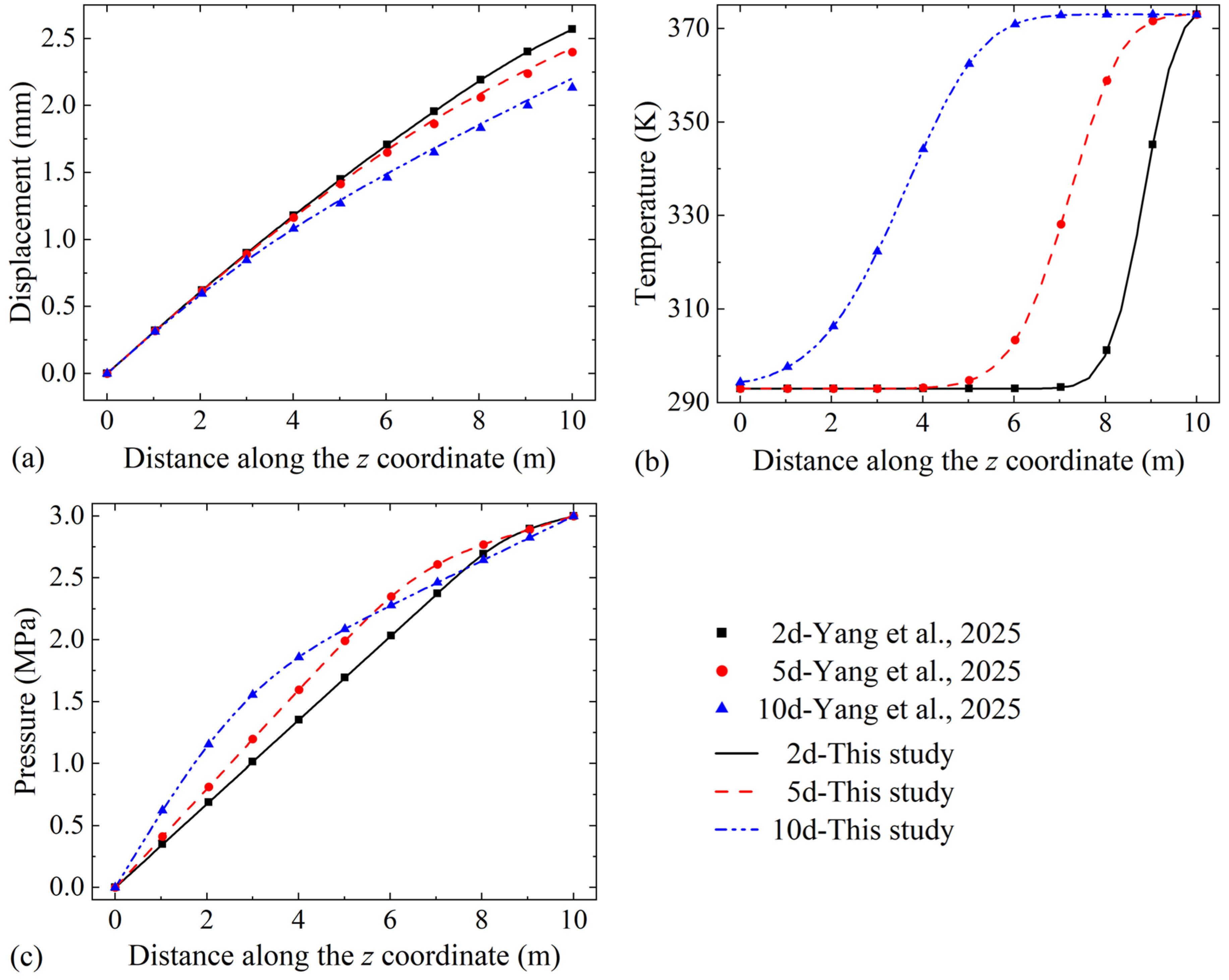
Yang et al. [24] computed the numerical solution for this problem. Under the same geometric configuration, material parameters, and boundary conditions, this study solved this problem using COMSOL Multiphysics. Since we did not know the mesh configuration used by Yang et al., in our validation model, we could only set up the mesh empirically, ensuring computational accuracy and convergence while avoiding unnecessary consumption of computing resources. The number of mesh elements in the validation model is 24,509. Figure 3 presents a comparison of the displacement, fluid temperature, and pressure obtained on days 2, 5, and 10 with those reported by Yang et al. The temperature and pressure results matched completely between this study and Yang et al., with only slight deviations in the displacement results near the inlet, which remain within an acceptable range. Therefore, it can be considered that the THM coupling model in this study is reliable.

3.3. Model Implementation

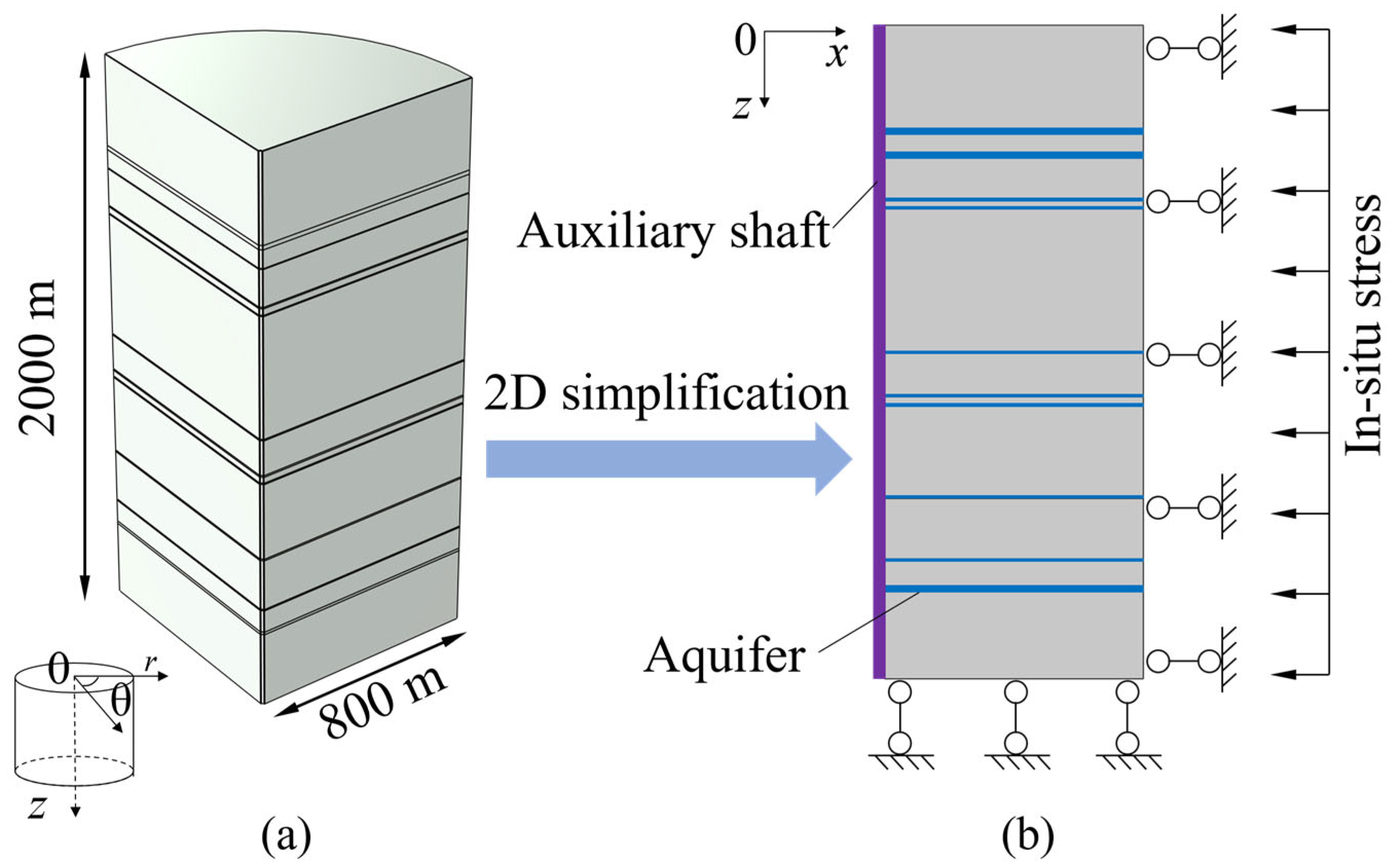
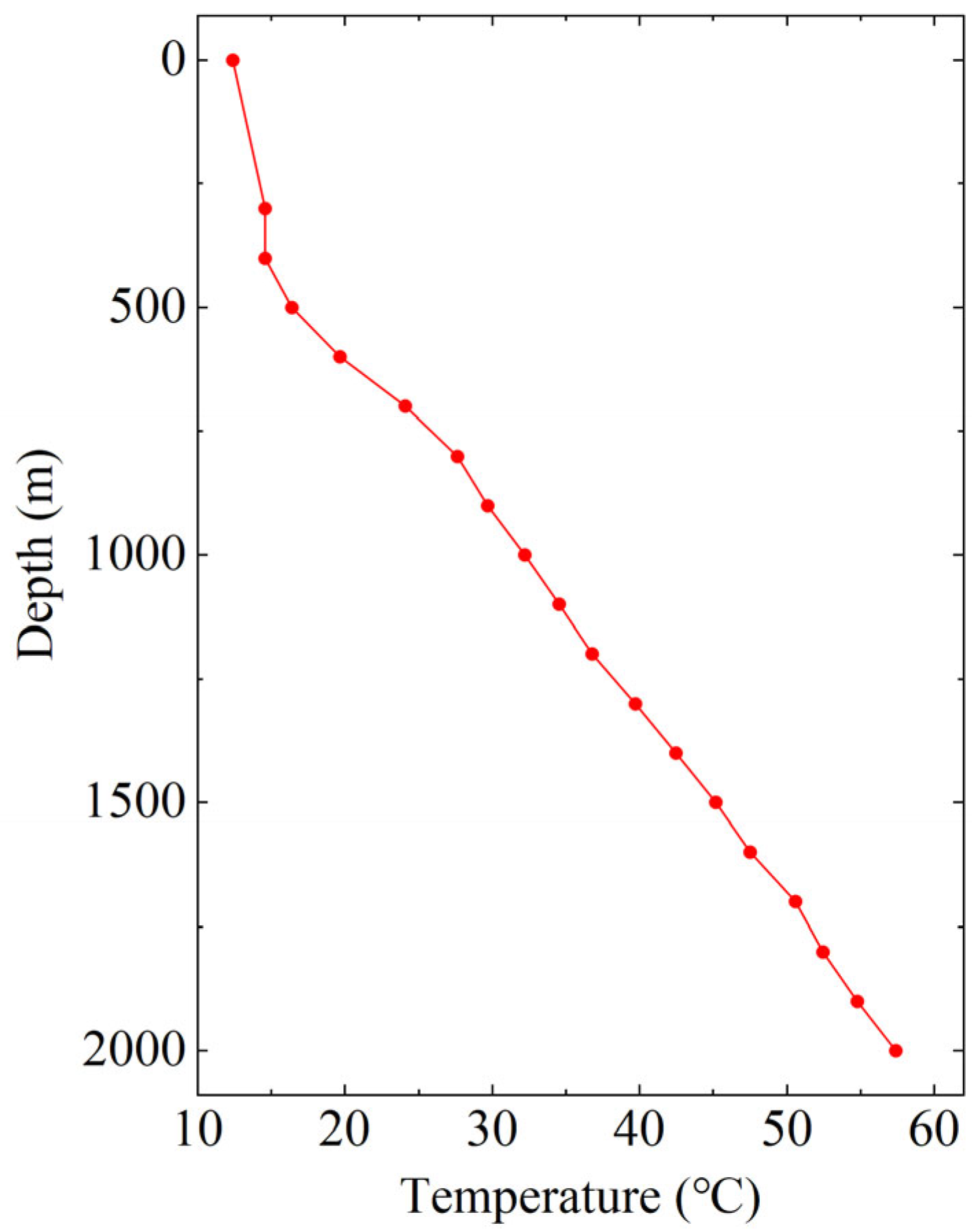
The mining disturbed area investigated in this study is represented by a cylindrical domain with a radius of 800 m and a depth of 2000 m. Since the structure is axisymmetric with respect to the axis of the excavation shaft, it is simplified into a two-dimensional axisymmetric model to reduce computational cost, as illustrated in Figure 4. The computational domain is a rectangular region of 800 m × 2000 m. The radius of the excavated auxiliary shaft is 8 m. The right boundary of the surrounding rock is constrained in the normal direction while subjected to the maximum in situ stress of the region. This boundary condition is designed to simulate an infinite surrounding rock using a finite domain. The bottom boundary of the model is defined as a roller support, restricting displacement in the z-direction while allowing displacement in the x-direction. The left boundary corresponds to the excavation shaft: prior to excavation, the shaft axis is set as a symmetric boundary; this point is used for the stress field, seepage field, and temperature field. That is, constrained normal displacement, impermeable, and thermal insulation. After excavation, it is defined as a free boundary. The blue zones represent the aquifer, with its dimensions and initial hydraulic head obtained from pumping tests, as detailed in Table 2. The pressure at the right boundary of the aquifer is set equal to the initial surrounding rock pressure. After excavation, the pressure at the shaft wall is set to atmospheric pressure. The surrounding rock temperature, determined through exploration, varies with depth, as shown in Figure 5. The right boundary temperature is the initial surrounding rock temperature. After excavation, the shaft wall is exposed to air, causing convection cooling. The air temperature is the annual average temperature of Laizhou City, 12.4 °C. The convective heat transfer coefficient is 20 W/(m2·K), which is slightly higher than the convective heat transfer coefficient for still air. This is because the excavated shaft is ventilated to ensure sufficient oxygen. The upper boundary of the surrounding rock is also in contact with air, which also means convection cooling. Therefore, the influence of excavation rate can be further investigated through the changes in boundary conditions before and after excavation. And the change in those boundary conditions is implemented using the ‘activation’ setting in COMSOL. The Young’s modulus values were derived from laboratory test results of rock samples obtained through field drilling and fitted using the ‘piecewise cubic’ interpolation method in COMSOL Multiphysics. For rock samples at certain depths with repeated tests, the average value was calculated and adopted as the Young’s modulus at that depth. Other parameters required for the simulation are listed in Table 4.
The numerical simulations were conducted using the finite element software COMSOL Multiphysics 6.3. The stress field, seepage field, and temperature field were solved by employing the Solid Mechanics module, the Darcy’s Law module, and the Heat Transfer in Porous Media module, respectively. The mesh is mainly composed of triangular elements, and to improve accuracy near the excavation boundary as well as ensure model convergence, eight boundary layers (quadrilateral elements) are set at the wellbore. The total number of elements was 28,520, including 25,176 triangular elements and 3344 quadrilateral elements. The ‘fully coupling’ solver was used for the solution, with the nonlinear method set to ‘automatic highly nonlinear’.

4. Results and Discussion

4.1. Stability Analysis

4.1.1. Stress Distribution Results

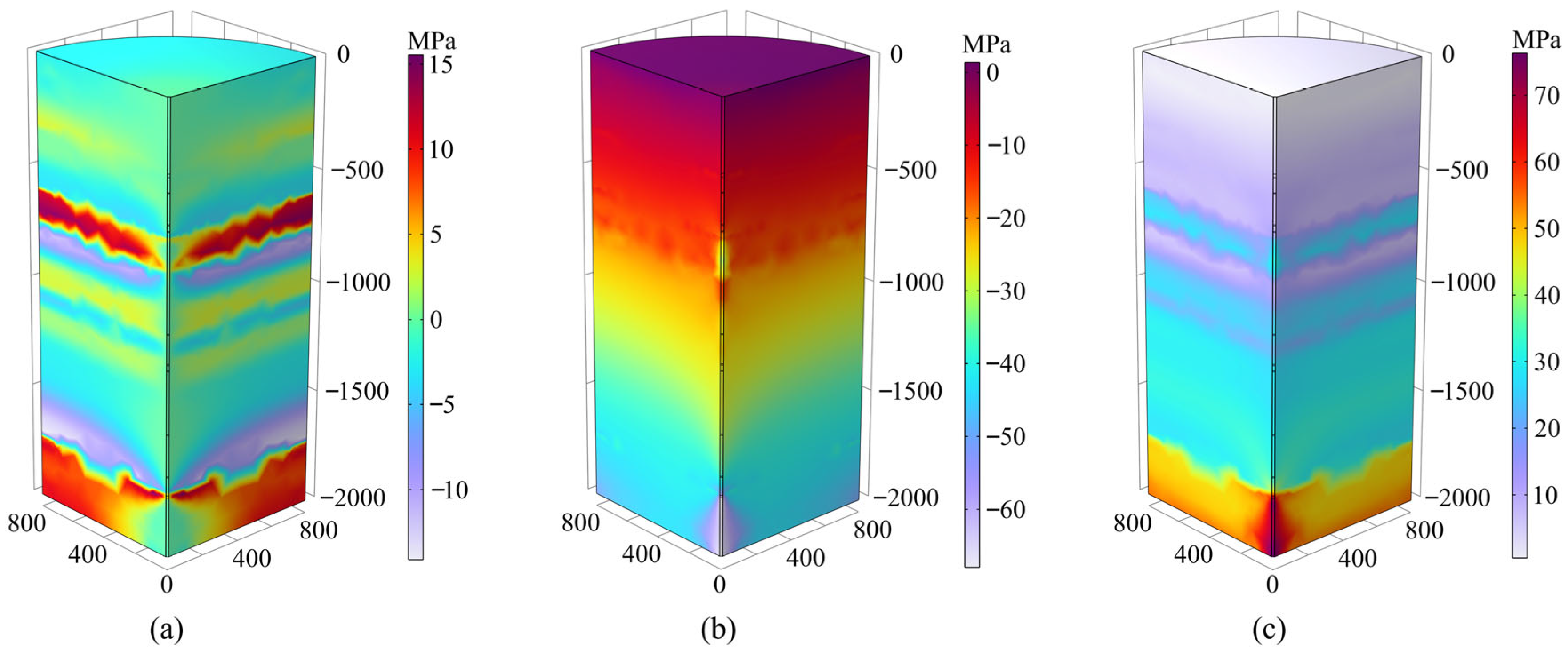
Figure 6 illustrates the stress distribution after excavation and upon reaching a stable state. The ‘stable state’ mentioned here refers to the condition where the stress field, seepage field, and temperature field of the surrounding rock after excavation have fully reached stability under natural conditions. This corresponds to a ‘steady-state’ calculation rather than a ‘transient-state’ calculation, in which the time-dependent terms in Equations (5) and (9) are neglected; the same applies in the following text. In Figure 6a, the radial stress corresponds to the x-direction in Figure 4, while in Figure 6b, the vertical stress corresponds to the z-direction in Figure 4. Tensile stress is considered positive, and compressive stress is considered negative. In Figure 6a, radial stresses in the surrounding rock are primarily concentrated within two depth intervals: 500–1000 m and 1500–2000 m. The maximum compressive stress reaches 15.9 MPa, and the maximum tensile stress reaches 14.1 MPa. From a rock mechanics perspective, such stress concentration is closely related to abrupt changes in the elastic modulus of the rock mass. Within these two depth ranges, variations in lithology or the presence of dense rock layers result in a significant increase in elastic modulus (see Table 1), thereby enhancing the stiffness of the rock mass. Under the same strain condition, regions with higher elastic modulus sustain higher stresses, leading to local extrema in stress at these depths.
Figure 6b shows that the vertical stress in the surrounding rock is primarily compressive, mainly induced by the overburden weight of the rock mass. As the depth of the surrounding rock increases, the vertical stress gradually increases, reaching a maximum of 70.0 MPa, which may lead to compressive deformation or even shear failure of the rock mass. Figure 6c presents the distribution of maximum effective stress, which reaches 76.4 MPa and exhibits a pronounced discontinuous layering pattern, primarily due to the heterogeneous distribution of aquifers within the mining area. According to the principle of effective stress, the presence of pore water pressure reduces the effective stress within the rock. Therefore, in the aquifer intervals, the pore pressure partially offsets the total stress, resulting in relatively lower effective stress [27]. This uneven distribution may induce differential deformation or the formation of local weak planes, and through the coupled effect of seepage and stress, may influence the long-term strength and deformation behavior of the rock mass [28].

4.1.2. Displacement Distribution Results

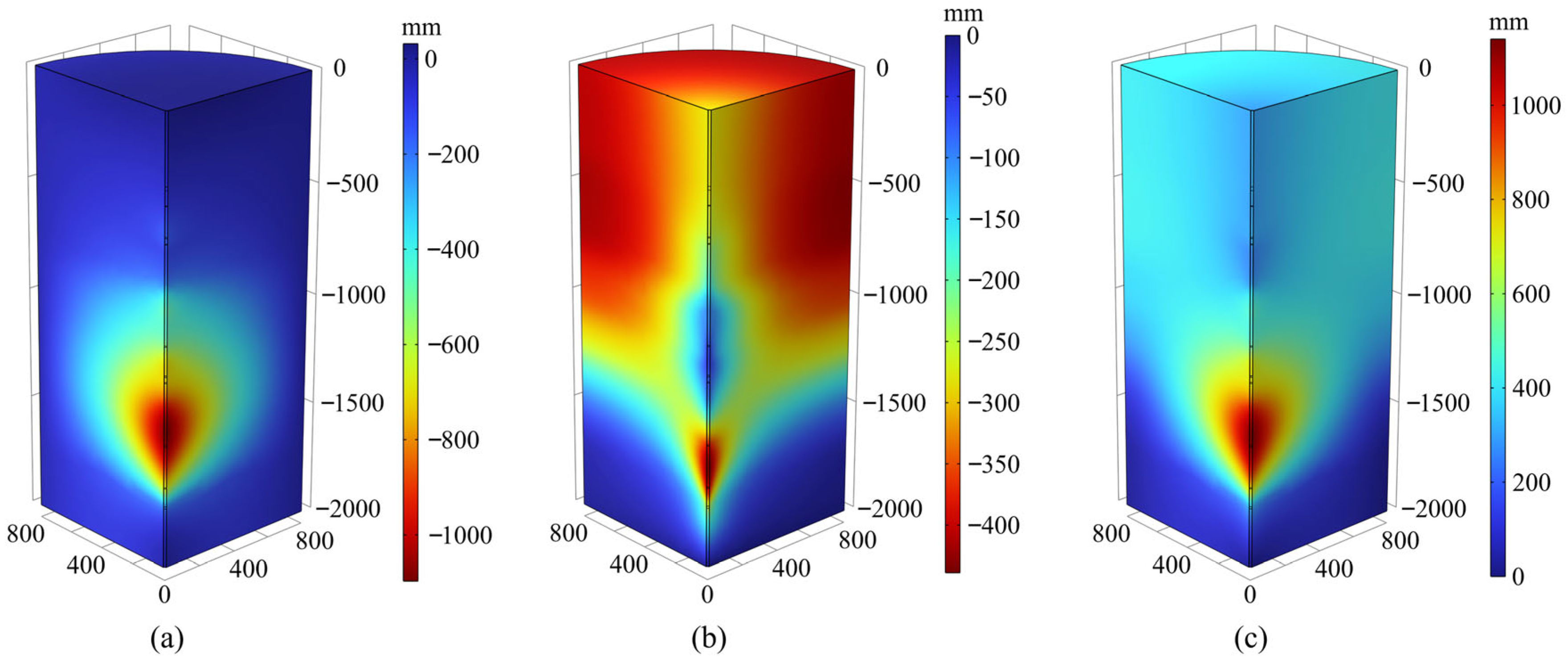
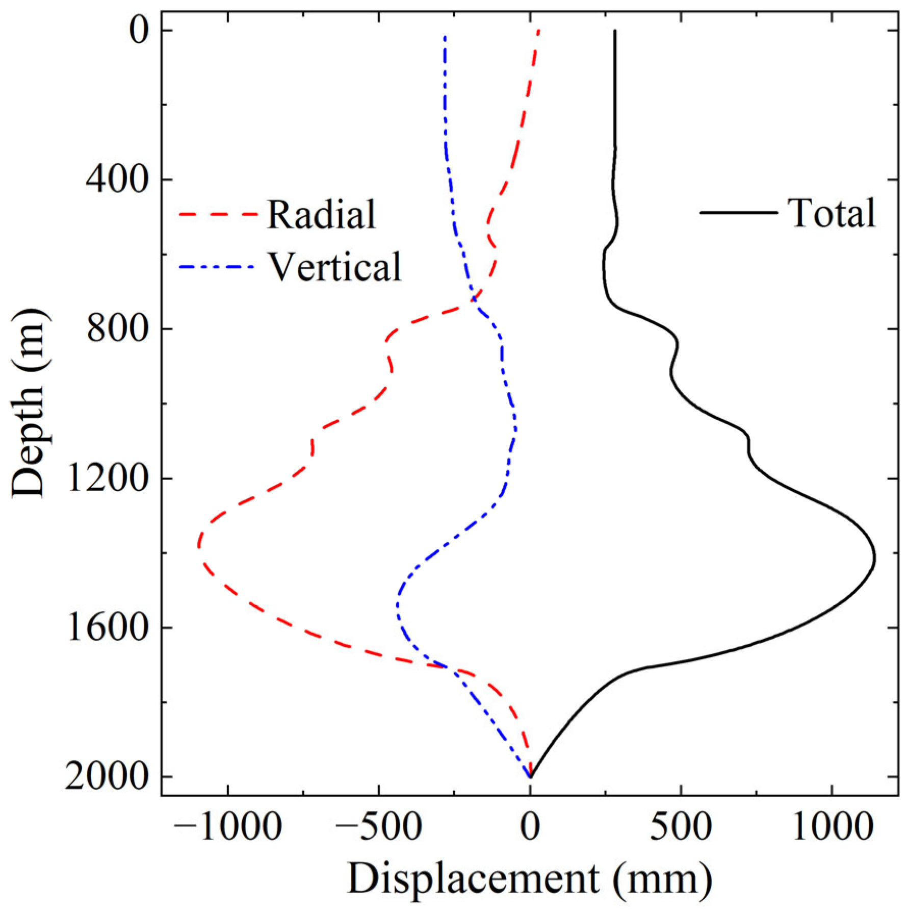
Figure 7 presents the displacement distribution of the surrounding rock after excavation upon reaching a stable state, while Figure 8 specifically illustrates the displacement results at the shaft wall. The total displacement represents the combined result of radial and vertical displacements, expressed as a scalar value. In Figure 7a, negative radial displacement indicates movement toward the wall of the excavation shaft (corresponding to the negative x-direction in Figure 4). This displacement is primarily caused by the loss of radial support around the shaft after unloading, leading to stress release and relaxation deformation of the surrounding rock toward the excavated cavity. The radial displacement at the well wall shows a nonlinear characteristic of first decreasing and then increasing with the increasing depth, gradually attenuating with distance from the excavation, reflecting the diminishing influence of excavation-induced disturbance. The maximum radial displacement reaches 1093 mm, occurring at a depth of approximately 1400 m, which corresponds to the layer within the surrounding rock with the lowest elastic modulus. According to elasticity theory, a rock with a lower elastic modulus undergoes greater strain under the same stress, resulting in pronounced deformation in this interval. In Figure 7b, negative vertical displacement indicates movement in the direction of gravity (corresponding to the negative z-direction in Figure 4). It is primarily induced by the settlement of the overlying rock mass under its own weight. This is also related to subsidence induced by the release of confined water and contraction of the rock due to the surrounding rock temperature decrease. Consequently, the overall vertical displacement generally increases with depth. However, within the vicinity of the excavation shaft, a slight rebound is observed at depths of 800–1200 m, followed by a sharp increase, reaching a maximum of approximately 446 mm at 1550 m.
The total displacement first increases and then decreases with the increase in depth, showing a distribution feature similar to that of radial displacement. Total displacement is particularly large near the shaft at a depth of 1400 m, with a maximum value of 1139 mm. Such substantial displacement may induce tensile or shear failure in the surrounding rock near the shaft [29], as well as promote the extension and interconnection of fracture networks, thereby reducing the overall stiffness and load-bearing capacity of the rock mass. Therefore, during both excavation and operation, the stability of this high-displacement zone requires particular attention. Systematic support measures are recommended, such as installing high-prestress anchors, applying lining, or employing grouting reinforcement, to provide additional confinement, suppress further deformation, and enhance both peak and residual rock strength, thereby effectively controlling the propagation of the failure zone and ensuring long-term stability of the shaft.

4.1.3. Pressure and Temperature Distribution Results

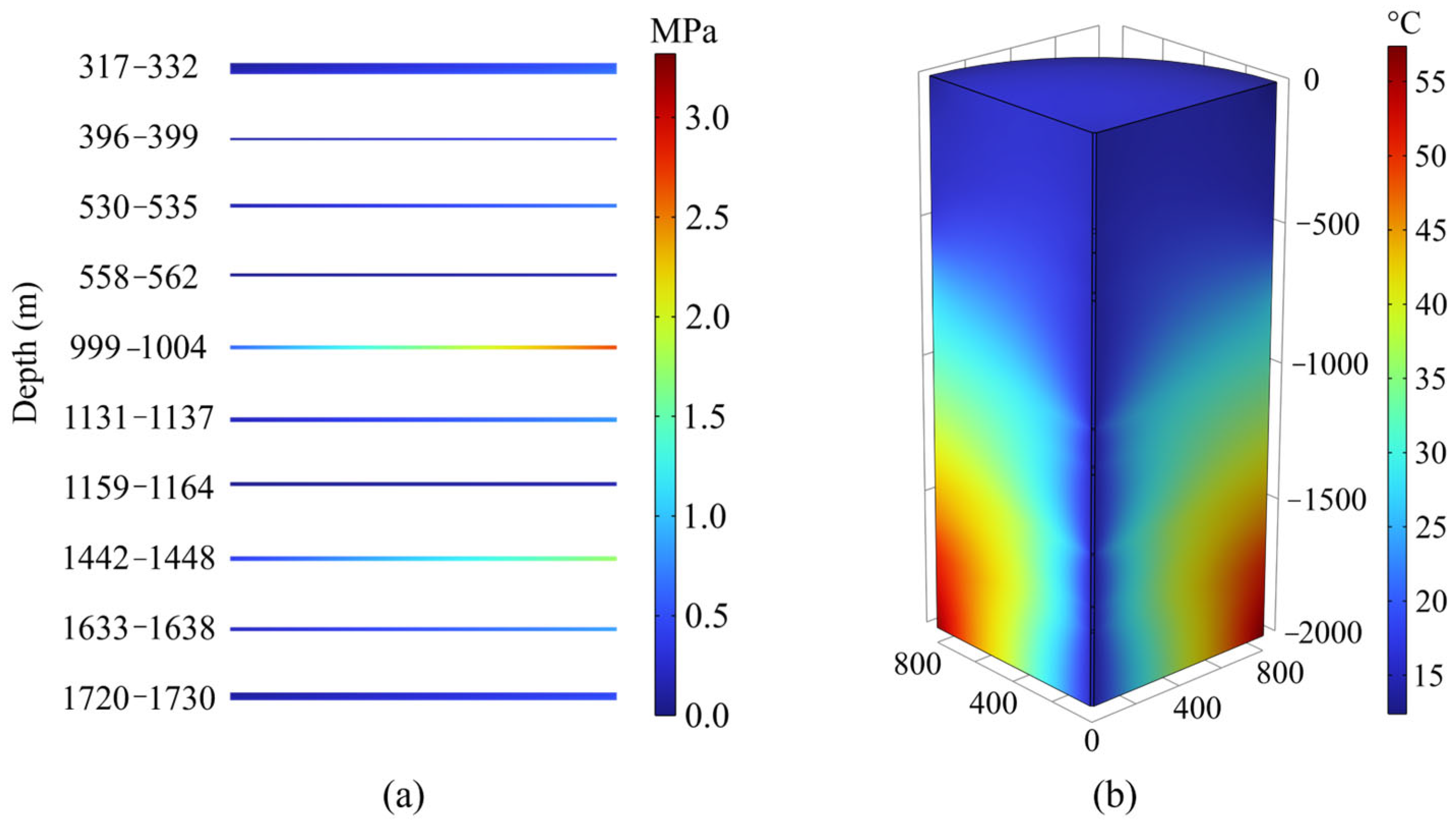
Figure 9 presents the distribution of pore pressure and temperature in the surrounding rock after reaching a stable state. Due to the relatively small thickness of the aquifer, a two-dimensional distribution map is used to better illustrate the results. The pore pressure exhibits a decreasing trend radially toward the excavation shaft. This is primarily because the excavation of the auxiliary shaft disrupts the integrity of the original hydrogeological structure, causing fluid within the aquifer to drain toward the shaft and resulting in a reduction in pore pressure. The decrease in pore pressure leads to a corresponding increase in effective stress. The rise in effective stress intensifies compressive deformation of the rock mass, thereby inducing surrounding rock subsidence [30,31]. The temperature distribution indicates a significant reduction in surrounding rock temperature near the excavation shaft, with the zone of low temperature gradually extending outward. The temperature decrease affects the stability of the surrounding rock in two ways: first, it induces rock contraction, thereby increasing vertical subsidence of the surrounding rock; second, the contraction may reduce radial strain, which in turn can partially decrease radial displacement toward the shaft.

4.2. The Effect of Excavation Rates

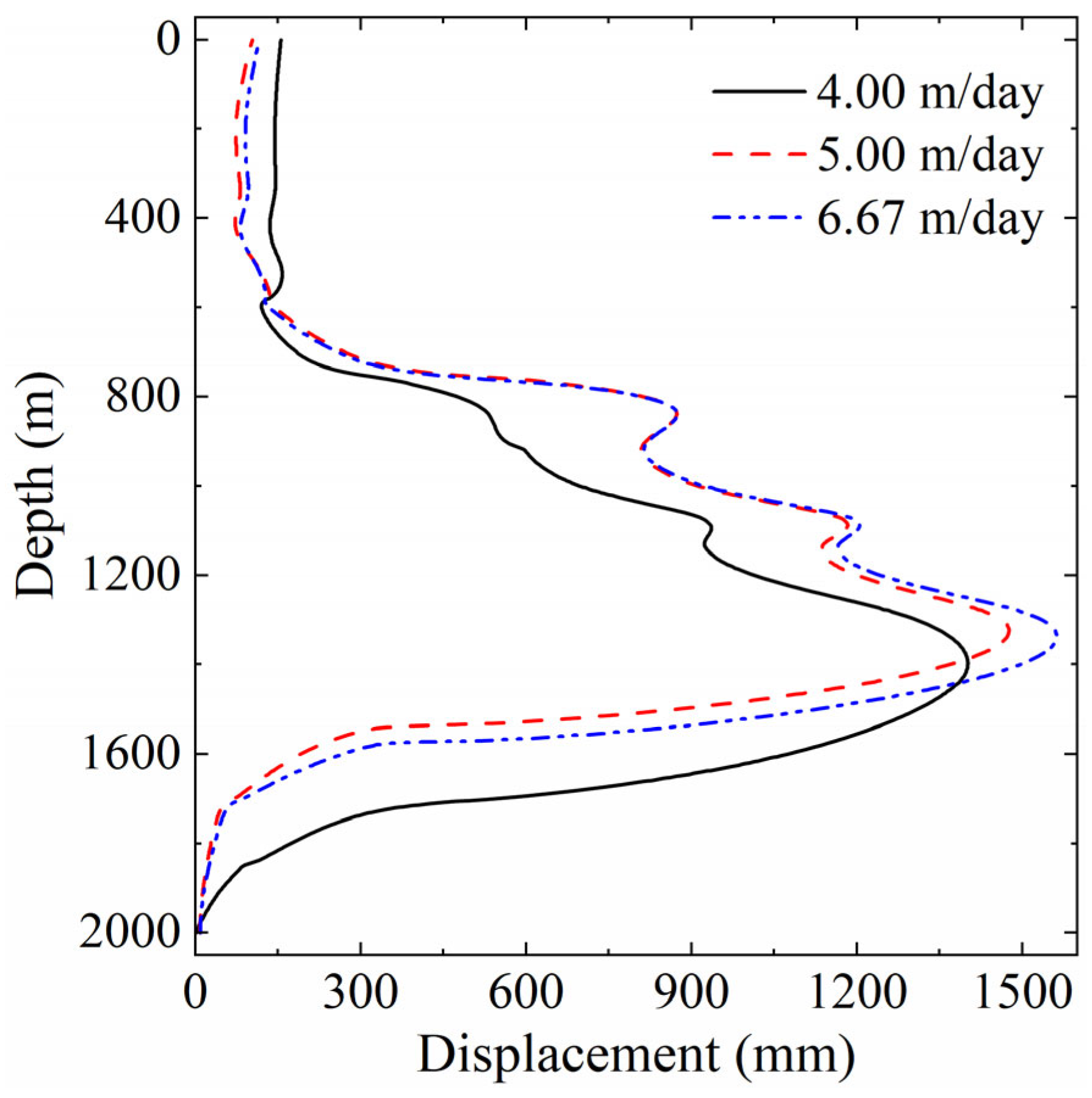
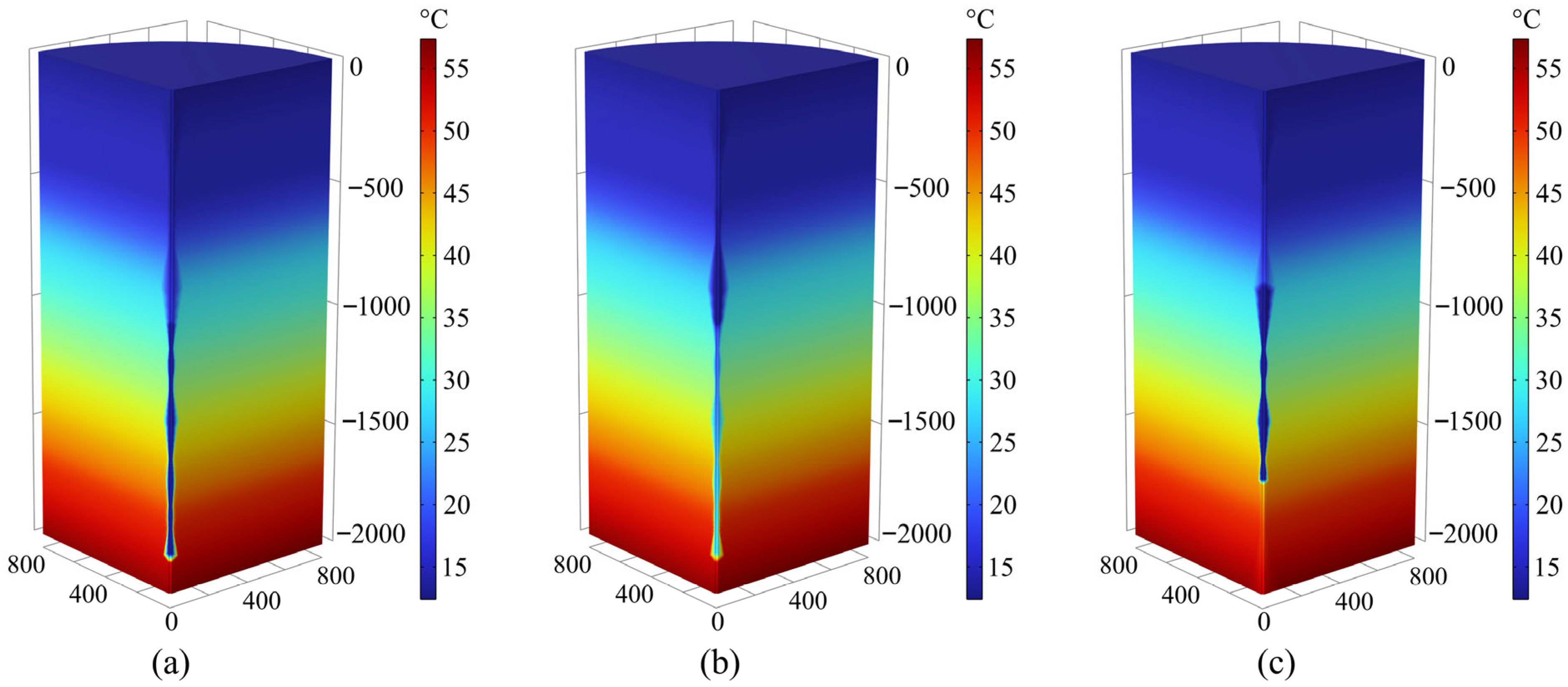
During excavation, the leakage of confined water and the dissipation of surrounding rock heat jointly drive the spatiotemporal evolution of surrounding rock deformation, constituting a typical transient thermal-hydraulic-mechanical (THM) coupling problem. As a key construction parameter, the excavation rate directly affects the redistribution of fluid pressure and temperature fields, thereby exerting a significant influence on the deformation response and stability of the surrounding rock. To this end, this study compares three excavation schemes with rates of 4 m/day, 5 m/day, and 6.67 m/day. For an auxiliary shaft with a depth of 2000 m, the total construction periods are 500, 400, and 300 days, respectively. The purpose of this section is to analyze the influence of excavation rate, taking into account the time-dependent terms in Equations (8) and (9), that is, transient-state calculations. The comparison of total wall displacements at excavation completion is presented in Figure 10.
The results reveal that the excavation rate has a considerable impact on shaft wall deformation: the faster the excavation, the larger the total wall displacement. As analyzed in Section 4.1.3, this phenomenon primarily arises from changes in effective stress and rock contraction induced by the combined effects of pore pressure release and temperature reduction during excavation. Since the aquifer thickness is relatively small compared to the entire surrounding rock, temperature change dominates the deformation mechanism. The low-temperature boundary of the wellbore wall after excavation will cause heat dissipation from the surrounding rock (see Section 3.3). As illustrated in Figure 11, a slower excavation rate corresponds to a longer construction period, during which heat exchange in the surrounding rock persists for a longer time. This leads to more pronounced temperature reduction and the consequent volumetric contraction of the rock mass. Such contraction partially suppresses the inward deformation of the shaft wall, resulting in smaller displacements under slow excavation conditions. It is worth noting that after the excavation operation is completed, thermal dissipation within the surrounding rock continues, leading to further rock contraction and subsequent deformation adjustment. This time-dependent behavior explains why the wall displacements observed at excavation completion (Figure 10) are larger than the stabilized displacements at full thermal equilibrium (Figure 8), highlighting the long-term effects of thermo-mechanical coupling and the delayed system response.
For depths shallower than 600 m, the trend is reversed, with lower excavation rates resulting in larger displacements. This may be because Figure 10 presents the total displacement, which is the combined result of radial and vertical displacements. At an excavation rate of 4 m/day, the slower excavation allows for a longer drainage process by the end of excavation, leading to more pronounced settlement in the upper part and consequently larger total displacement. For depths greater than 1400 m, larger displacements are also observed under lower excavation rates, which may be preliminarily attributed to differences in stress release mechanisms under varying excavation rates, though further investigation is needed. In addition, it is worth noting that the total displacement at excavation rates of 5 m/day and 6.67 m/day differs only at the point of maximum displacement, suggesting that there may be a threshold in the influence of excavation rate, which also requires further study.

4.3. Discussion

This study demonstrates that the deformation and stability evolution during the auxiliary shaft excavation are primarily governed by the thermo-hydro-mechanical (THM) coupling mechanism. Excavation induces pore pressure dissipation and temperature reduction, which in turn increase effective stress and cause rock contraction, jointly driving significant radial displacement and vertical subsidence. The displacement response is highly dependent on lithological distribution, with concentrated deformation occurring in low elastic modulus zones (e.g., around 1400 m depth), greatly increasing the risk of shear failure of the shaft wall and the development of tensile fractures [32]. Our displacement results are slightly larger than those of Hou et al. [4], which may be because their calculations were based solely on the stress field, whereas we also considered the seepage field and temperature field. After aquifer drainage, rock settlement occurs, which leads to our results being larger than those of Hou et al. [4]. Excavation rate further modulates the deformation process by influencing the duration of pressure release and heat exchange: faster excavation shortens the construction period but intensifies near-field disturbance and instantaneous displacement; slower excavation, on the other hand, allows thermal contraction to develop continuously, thereby suppressing radial displacement to some extent. Since the temperature and pressure continue to evolve after excavation, the surrounding rock has not reached a stable state, which reflects the necessity of long-term monitoring.
Based on the above analysis, the engineering practice of the Xiling auxiliary shaft at the Sanshandao Gold Mine should focus on the low-stiffness strata near 1400 m depth, where the largest displacement occurs and failure is most likely. It is recommended to adopt high-strength combined support measures in this critical zone, such as the collaborative use of high-preload long bolts and deformable linings, supplemented by grouting reinforcement to enhance the integrity and deformation resistance of the surrounding rock [7,33]. Meanwhile, the excavation rate should be optimized to balance construction efficiency and deformation control, and continuous monitoring of temperature, pore pressure, and displacement should be conducted after excavation to capture their long-term evolution, enabling timely maintenance measures to ensure the long-term stability and safe operation of the shaft.
The limitation of this model is that surrounding rock heterogeneity in the horizontal direction is not considered; parameters such as Young’s modulus and Poisson’s ratio are assumed constant laterally and only varied with depth. In addition, the presence of faults or fractures is not included. However, in the study by Hou et al. [4], it was found that the extent of the damaged area would increase significantly when the wellbore passed through a fracture zone or different lithology. These limitations stem from the lack of geological data as well as considerations of model complexity. Nevertheless, the model is sufficient to achieve the objective of this study, which is to investigate the THM coupling process and stability during ultra-deep auxiliary shaft excavation.

5. Conclusions

This study focuses on the excavation stability of the Xiling auxiliary shaft at the Sanshandao Gold Mine under complex geological conditions and thermal–hydraulic–mechanical (THM) coupling processes. A fully coupled THM numerical model was established to systematically analyze stress redistribution, deformation mechanisms, and stability responses during excavation, and the influence of different excavation rates on surrounding rock behavior is evaluated. The main conclusions are as follows:
(1)
Stress redistribution induced by auxiliary shaft excavation is significantly influenced by the spatial variability of rock mechanical properties. Stress concentration occurs in rock layers with high elastic modulus (depth 500–1000 m and 1500–2000 m), where compressive stress peaks at 15.9 MPa and tensile stress reaches 14.1 MPa, making compressive-shear or tensile failure likely. The vertical stress, mainly resulting from the overburden weight, reaches a maximum of 70.0 MPa, aggravating the risk of compressive deformation in the surrounding rock.
(2)
Surrounding rock deformation strongly depends on lithology and the THM coupling process. The maximum displacement occurs in the low elastic modulus zone (around 1400 m depth), with a total displacement of 1139 mm. This is primarily manifested as radial displacement toward the shaft and settlement in the gravity direction, jointly induced by unloading, pore pressure reduction, and thermal contraction.
(3)
Excavation rate has a significant impact on deformation response. Faster excavation (e.g., 6.67 m/day) causes more pronounced instantaneous displacement, while slower excavation (e.g., 4 m/day) partially suppresses displacement due to the persistent effect of thermal contraction. Post-excavation, the thermo-mechanical coupling process continues, indicating a pronounced time-dependent and delayed deformation effect.
(4)
Special attention should be paid to the low-stiffness rock strata around 1400 m depth during excavation. A combined support strategy is recommended, involving high-preload rock bolts, lining, and grouting reinforcement, along with optimized excavation rates. Long-term monitoring of temperature, pore pressure, and displacement is essential to achieve dynamic risk control.
The findings of this study provide a theoretical basis and engineering guidance for stability evaluation and safety control of deep mine shafts under multi-physical coupling conditions, particularly the Xiling auxiliary shaft.

Author Contributions

Conceptualization, G.W. and X.D.; methodology, G.W., X.D., L.Y., Z.S. and B.H.; software, W.F. and Z.S.; validation, G.W., Z.S. and B.H.; formal analysis, W.F.; investigation, G.W., W.F., X.D., L.Y., Z.S. and B.H.; resources, W.F. and B.H.; data curation, X.D. and B.H.; writing—original draft preparation, G.W., W.F. and X.D.; writing—review and editing, X.D., L.Y., Z.S. and B.H. All authors have read and agreed to the published version of the manuscript.

Funding

This research was funded by the major science and technology project of China Middling Coal (Grant No. 20231BY001).

Data Availability Statement

Data will be made available on request.

Conflicts of Interest

Author Guoyuan Wang, Wenbo Fan, Xiansong Deng were employed by the company China Coal Construction Group Limited Corporation. Author Zhaoyang Song was employed by the company Beijing China Coal Mine Engineering Company Limited. The remaining authors declare that the research was conducted in the absence of any commercial or financial relationships that could be construed as a potential conflict of interest.

Abbreviations

The following abbreviations are used in this manuscript:
THMthermal–hydraulic–mechanical

References

  1. Wu, F.; Qin, Y.; Xu, H.; Zhang, F.; Chu, X. Numerical Simulation of Deformation and Failure Mechanism of Main Inclined Shaft in Yuxi Coal Mine, China. Appl. Sci. 2022, 12, 5531. [Google Scholar] [CrossRef]
  2. Li, C.; Chunlong, W.; Xi, W.; Kexu, C.; Song, Z. Stability Analysis of Surrounding Rock of Large Section Ultradeep Shaft Wall. Adv. Mater. Sci. Eng. 2021, 2021, 4391759. [Google Scholar] [CrossRef]
  3. Yang, S.-Q.; Chen, M.; Jing, H.-W.; Chen, K.-F.; Meng, B. A case study on large deformation failure mechanism of deep soft rock roadway in Xin’An coal mine, China. Eng. Geol. 2017, 217, 89–101. [Google Scholar] [CrossRef]
  4. Hou, K.; Zhu, M.; Hao, Y.; Yin, Y.; An, L. Stability analysis and evaluation of surrounding rock of ultra-deep shaft under complicated geological conditions. Front. Earth Sci. 2023, 11, 1216667. [Google Scholar] [CrossRef]
  5. Tan, J.; Liu, Z.; Song, Z.; Liu, Q.; Long, Z.; Ning, F. Status and Development Trend of Mine Shaft Sinking Technique in China. Met. Mine 2021, 539, 12–24. [Google Scholar]
  6. Hall, A.; Cai, M.; Simser, B.; Lindsay, J. Notch formation in vertical excavations in a deep hard rock mine and rock stabilization methodologies. Deep Resour. Eng. 2024, 1, 100003. [Google Scholar] [CrossRef]
  7. Wang, E.; Yin, S.; Cheng, Z.; Xie, S.; Chen, L.; Kang, Q.; Duan, Y. Failure mechanism analysis of ultra-large-section soft-rock roadway in kilometer deep coal mine and its collaborative control of “grouting-anchoring-pouring”. Eng. Fail. Anal. 2025, 170, 109338. [Google Scholar] [CrossRef]
  8. Shu, S.; Yao, Z.; Xu, Y.; Fang, Y.; Wang, J.; Wang, F. Permeability characteristics and damage constitutive model of CA-UHPC in deep frozen shaft linings under stress-seepage coupling. Constr. Build. Mater. 2025, 484, 141824. [Google Scholar] [CrossRef]
  9. Lu, G.; Liu, J.; Ma, C.; Liu, L.; Tao, J. Thermal-mechanical stability of subsurface excavation in hostile geothermal environment subject to active cooling protocols. Tunn. Undergr. Space Technol. 2025, 166, 106939. [Google Scholar] [CrossRef]
  10. Zhang, L.; Dieudonné, A.-C.; Daniilidis, A.; Dong, L.; Cao, W.; Thibaut, R.; Tas, L.; Hermans, T. Thermo-hydro-mechanical modeling of geothermal energy systems in deep mines: Uncertainty quantification and design optimization. Appl. Energy 2025, 377, 124531. [Google Scholar] [CrossRef]
  11. Qin, S.; Zhao, X.; Wu, T.; Song, J.; Cao, X. Comprehensive prevention and control research on rockburst in ultradeep shaft based on theoretical deepening and practical verification. Tunn. Undergr. Space Technol. 2025, 164, 106805. [Google Scholar] [CrossRef]
  12. Xiao, P.; Li, D.; Zhao, G.; Zhu, Q. Characteristics and mechanism of rockburst at five deep gold mines in Jiaodong Peninsula of China. Int. J. Rock Mech. Min. Sci. 2023, 171, 105574. [Google Scholar] [CrossRef]
  13. Wen, J.; Zuo, J.; Wang, Z.; Wen, Z.; Wang, J. Failure mechanism analysis and support strength determination of deep coal mine roadways—A case study. Constr. Build. Mater. 2024, 443, 137704. [Google Scholar] [CrossRef]
  14. Hall, A.; Cai, M.; O’Connor, C.; Yadav, P.; Simser, B. Simulation of progressive notch failure in deep bored raises using an iterative approach in FLAC3D. Deep Resour. Eng. 2025, 2, 100197. [Google Scholar] [CrossRef]
  15. Yang, J.; Wang, J.G.; Liang, W.; Li, P.; Sun, R. Optimal selection of working fluid for enhanced geothermal systems: A comparative analysis of supercritical carbon dioxide and water under various reservoir and extraction conditions. Appl. Therm. Eng. 2024, 246, 122947. [Google Scholar] [CrossRef]
  16. Li, P.; Wang, J.; Liang, W.; Yang, J.; Zhang, Z.; Xu, K. A New Machine Learning-Based Prediction Approach for the Fracability of Deep Reservoirs. Nat. Resour. Res. 2025, 34, 2599–2626. [Google Scholar] [CrossRef]
  17. Hu, B.; Wang, J.; Ma, Z.; Sang, S. Permeability and thermal conductivity models of shale matrix with a bundle of tortuous fractal tree-like branching micropore networks. Int. J. Therm. Sci. 2021, 164, 106876. [Google Scholar] [CrossRef]
  18. Yang, J.; Wang, J.; Hu, B. Numerical Analysis of the Impacts of Multiscale Fractures on Geothermal Reservoir Capacity. J. Energy Eng. 2023, 149, 04023046. [Google Scholar] [CrossRef]
  19. Chen, S.; Zhu, H.; Zhao, P.; Wang, Y.; Song, R.; Zuo, Y.; Shi, Y.; Zhou, T. Influence of fracture network characteristics of hot dry rock on heat extraction performance: A numerical simulation study. Geoenergy Sci. Eng. 2025, 245, 213523. [Google Scholar] [CrossRef]
  20. Li, P.; Wang, J.; Liang, W.; Yang, J. Study on CO2 fracturing in deep tight sandstone considering the in-situ stress gradient and thermal stress. Comput. Geotech. 2024, 174, 106599. [Google Scholar] [CrossRef]
  21. Lu, W.; Zhang, X. Coupled thermo-hydro-mechanical modelling of carbon dioxide sequestration in saline aquifers considering phase change. Curr. Sci. 2020, 119, 973–983. [Google Scholar] [CrossRef]
  22. Xue, K.; Pu, H.; Li, M.; Luo, P.; Liu, D.; Yi, Q. Fractal-based analysis of stress-induced dynamic evolution in geometry and permeability of porous media Available to Purchase. Phys. Fluids 2025, 37, 036630. [Google Scholar] [CrossRef]
  23. Xu, T.; Pruess, K.; Apps, J. Numerical studies of fluid-rock interactions in Enhanced Geothermal Systems (EGS) with CO2 as working fluid. In Proceedings of the Thirty-Third Workshop on Geothermal Reservoir Engineering, Stanford, CA, USA, 28–30 January 2008. [Google Scholar]
  24. Yang, J.; Wang, J.G.; Li, P.; Liang, W.; Leung, C. A Novel Progressive Many-Objective Optimization Approach for Engineering-Controllable Parameters of an Enhanced Geothermal System in the Gonghe Basin, China. Math. Geosci. 2025, 57, 1327–1355. [Google Scholar] [CrossRef]
  25. Gong, F.; Guo, T.; Sun, W.; Li, Z.; Yang, B.; Chen, Y.; Qu, Z. Evaluation of geothermal energy extraction in Enhanced Geothermal System (EGS) with multiple fracturing horizontal wells (MFHW). Renew. Energy 2020, 151, 1339–1351. [Google Scholar] [CrossRef]
  26. Chen, Y.; Wang, H.; Li, T.; Wang, Y.; Ren, F.; Ma, G. Evaluation of geothermal development considering proppant embedment in hydraulic fractures. Renew. Energy 2020, 153, 985–997. [Google Scholar] [CrossRef]
  27. Pu, H.; Xue, K.; Wu, Y.; Zhang, S.; Liu, D.; Xu, J. Estimating the permeability of fractal rough rock fractures with variable apertures under normal and shear stresses. Phys. Fluids 2025, 37, 036635. [Google Scholar] [CrossRef]
  28. Li, M.-G.; Yan, Y.-H.; Xu, Z.-H.; Chen, H.-B.; Peng, C.-X.; Chen, J.-J. Fully hydro-mechanical coupled analyses of the deep excavation above a multi-aquifer-aquitard system. Tunn. Undergr. Space Technol. 2025, 156, 106259. [Google Scholar] [CrossRef]
  29. Zhu, X.; Ji, H.; Liu, R.; Yu, L.; Wang, Y. Numerical study of hydraulic characteristics of shale fractures during unloading-induced slipping: Effects of inclination angle and unloading rate. Comput. Geotech. 2023, 164, 105811. [Google Scholar] [CrossRef]
  30. Chu, Z.; Wu, Z.; Liu, B.; Wu, K.; Shi, X.; Liu, Q. Mechanical response of inclined TBM tunnel due to drainage settlement of deep sandstone aquifer. Tunn. Undergr. Space Technol. 2022, 122, 104393. [Google Scholar] [CrossRef]
  31. Zhu, X.; Liu, R.; Li, W.; Qiao, W.; Wei, M.; Yu, L. Correcting the Permeability Evaluation of Elliptical Rock Fractures in Triaxial Shear-Flow Experiments Considering Channeling Flow. Rock Mech. Rock Eng. 2023, 57, 1509–1523. [Google Scholar] [CrossRef]
  32. Li, C.C. Field observations and interpretation of extensional fracture in hard rock surrounding deep underground openings. Deep Resour. Eng. 2024, 1, 100006. [Google Scholar] [CrossRef]
  33. Hashemi, S.; Ashcroft, B.; Chittenden, N.; Gwildis, U.; Heine, J.; Luxford, J.; Marquis, F.; Nasri, V.; Preene, M.; Shaterpour-Mamaghani, A.; et al. Selection of shaft construction method. Tunn. Undergr. Space Technol. 2025, 164, 106654. [Google Scholar] [CrossRef]
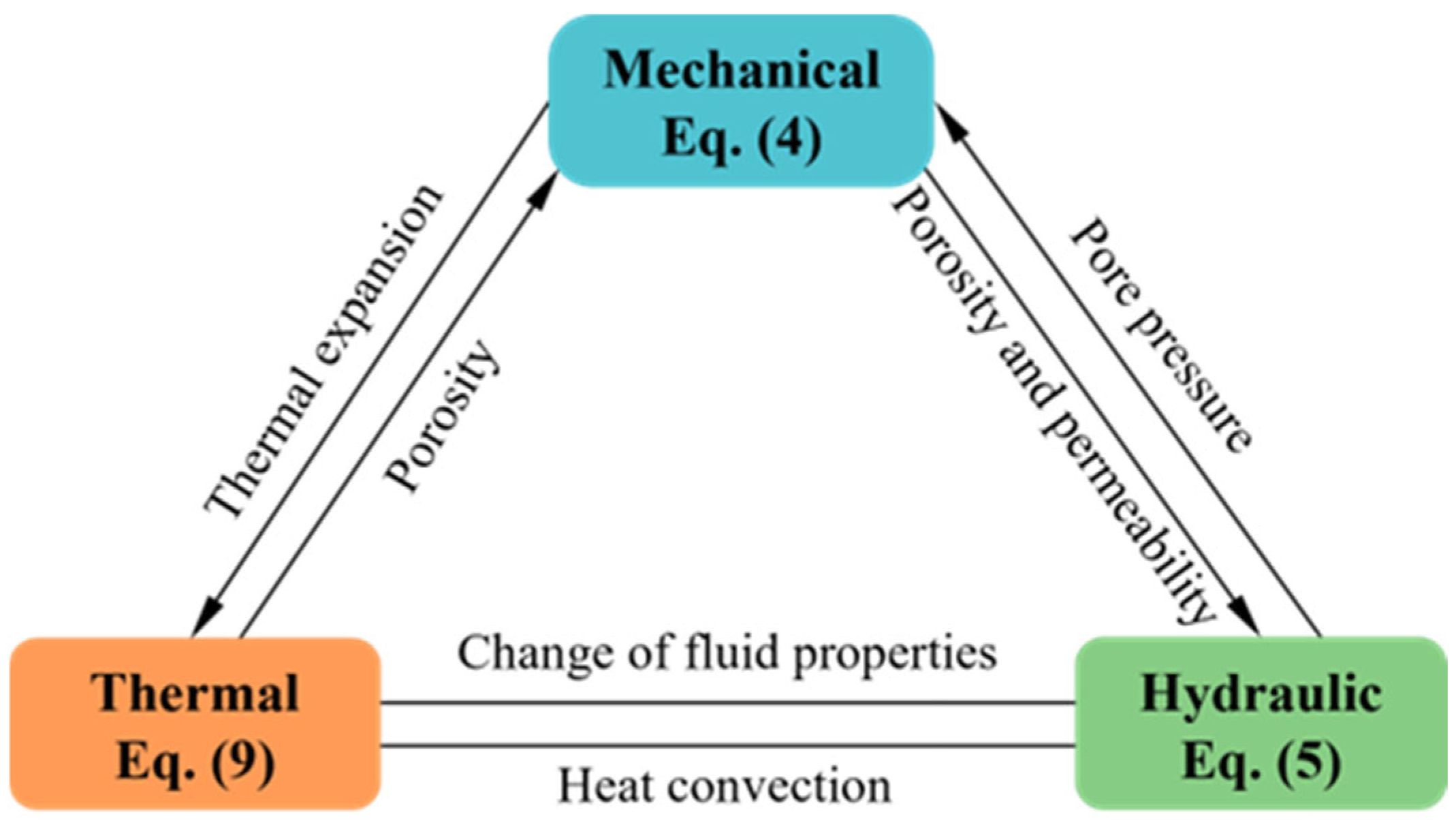
Figure 1. The coupling interactions among thermal, hydraulic, and mechanical fields.
Applsci 15 12433 g001
Figure 2. The cuboid model for validation.
Applsci 15 12433 g002
Figure 3. Validation of the THM coupling model: (a) displacement (mm); (b) temperature (K); (c) pressure (MPa) [24].
Applsci 15 12433 g003
Figure 4. Geometry structure of the THM model: (a) 3D model; (b) 2D model.
Applsci 15 12433 g004
Figure 5. Initial temperature of surrounding rock.
Applsci 15 12433 g005
Figure 6. Surrounding rock stress distribution results: (a) radial stress σ r r ; (b) vertical stress σ z z ; (c) effective σ .
Applsci 15 12433 g006
Figure 7. Surrounding rock displacement distribution results: (a) radial displacement urr; (b) vertical displacement uzz; (c) total displacement utot.
Applsci 15 12433 g007
Figure 8. Displacement on the shaft wall.
Applsci 15 12433 g008
Figure 9. Surrounding rock pressure and temperature distribution results: (a) pressure; (b) temperature.
Applsci 15 12433 g009
Figure 10. The total displacements on shaft wall at excavation completion under different rates.
Applsci 15 12433 g010
Figure 11. Temperature distribution at excavation completion under different rates: (a) 4 m/day; (b) 5 m/day; (c) 6.67 m/day.
Applsci 15 12433 g011
Table 1. The physical and mechanical properties of the rocks.
NumberDepthTensile StrengthUniaxial Compressive StrengthFriction AngleElastic ModulusPoisson’s Ratio
mMPaMPa°GPa1
SSD19-14.73–16.931.8426.1043.623.300.23
3.9832.7019.700.30
2.344.5031.600.18
SSD19-2 38.00–55.006.4342.7259.43.750.11
SSD19-19100.00–300.006.6313256.567.30.06
10.213555.20.05
8.9815047.90.08
SSD19-3 340.00–400.004.9137.66 5.980.02
SSD19-4 525.00–580.004.4954.4042.837.690.27
SSD19-20600.00–700.008.2314556.357.50.06
6.4412358.80.05
6.9311264.70.11
SSD19-5 760.00–800.006.0560.7958.075.300.40
SSD19-6 935.00–1000.005.3528.9953.115.500.05
SSD19-7 1000.00–1050.005.4673.0044.214.760.21
SSD19-8 1050.00–1064.006.1528.2755.863.960.24
SSD19-9 1140.00–1170.005.8346.3444.582.750.05
SSD19-10 1300.00–1400.005.3146.7145.171.840.12
SSD19-11 1650.00–1700.003.2535.1036.435.170.27
SSD19-131722.96–1728.163.3860.6053.521.80.20
4.5642.6020.50.11
4.8245.9026.10.09
SSD19-141728.66–1740.463.9458.7054.336.20.14
4.9962.3038.80.12
5.8368.9046.30.05
SSD19-151740.46–1756.767.3011653.343.50.09
6.6810757.30.13
6.5372.942.30.06
SSD19-161800.00–1870.007.3612653.450.50.10
8.3111747.90.09
9.1314448.80.03
SSD19-171960.00–1980.007.1611354.459.80.07
8.8112645.40.12
6.7110347.40.04
SSD19-181974.00–1983.007.5414158.385.70.03
12.011892.20.09
9.4816195.20.10
SSD19-211990.00–2000.007.5887.853.652.50.11
5.7011063.80.12
6.1611753.90.13
SSD19-222000.00–2015.002.5319.245.29.320.45
2.1728.911.00.34
2.9427.27.950.24
Table 2. Pumping test results and predicted permeability coefficients.
Pumping Test StageDepthDepth of Static Water LevelWater Level DropsAquifer ThicknessHydraulic ConductivityWater Inflow
mmmmm/dm3/d
II317.00–332.00218.50113.5015.000.084331174.33
396.00–399.00332.0067.003.000.08433125.72
530.00–535.00399.00136.005.000.08433169.31
558.00–562.00535.0027.004.000.08433119.41
I999.00–1004.00562.00442.005.000.04617097.02
1131.00–1137.001004.00133.006.000.04617047.45
1159.00–1164.001137.0027.005.000.04617014.51
1442.00–1448.001164.00284.006.000.04617082.82
1633.00–1638.001448.00190.005.000.04617051.29
1720.00–1730.001638.0092.0010.000.04617059.81
Table 3. Simulation parameters for model verification.
ParametersUnitValue
Elastic modulus of rockGPa30
Poisson’s ratio10.15
Biot’s coefficient-1.0
Water storage coefficient1/Pa1 × 10−9
Thermal expansion coefficient1/K5.0 × 10−7
Rock permeabilitym21 × 10−14
Rock porosity-0.2
Fluid densitykg/m31000
Thermal conductivity of fluidJ/(m·K·s)0.6
Thermal conductivity of rockJ/(m·K·s)3.5
Heat capacity of fluidJ/(kg·K)4200
Heat capacity of rockJ/(kg·K)790
Table 4. Parameters for the simulation.
ParametersUnitValue
Initial rock porosity-0.15
Biot’s coefficient-1.0
Thermal expansion coefficient1/K5.0 × 10−6
Density of rockkg/m32500
Thermal conductivity of rockW/(m·K)3.0
Heat capacity of rockJ/(kg·K)800
Disclaimer/Publisher’s Note: The statements, opinions and data contained in all publications are solely those of the individual author(s) and contributor(s) and not of MDPI and/or the editor(s). MDPI and/or the editor(s) disclaim responsibility for any injury to people or property resulting from any ideas, methods, instructions or products referred to in the content.