Article

Vibration Analysis of Cantilever Beam with Free End Resting on 3D-Printed Spring and Considering the Effect of Accelerometer and Exciter Masses

1
Engineering Technical College-Baghdad, Middle Technical University, Baghdad 10098, Iraq
2
Departamento de Deseño na Enxeñaría, Universidade de Vigo, 36310 Vigo, Spain
3
Institute of Applied Arts, Middle Technical University, Baghdad 10074, Iraq
4
Department of Manufacturing Processes and Production Engineering, Rzeszow University of Technology, al. Powst. Warszawy 8, 35-959 Rzeszów, Poland
*
Author to whom correspondence should be addressed.
Appl. Sci. 2025, 15(22), 12344; https://doi.org/10.3390/app152212344
Submission received: 15 October 2025 / Revised: 12 November 2025 / Accepted: 18 November 2025 / Published: 20 November 2025
(This article belongs to the Section Additive Manufacturing Technologies)

Abstract

A cantilever beam is a mechanical structure fixed at one end and free at the other. It converts the applied external forces into bending and shear force; therefore, it should be designed to resist deflection. The fundamental natural frequency of the cantilever beam depends on its material properties, geometry, and supporting conditions. This work studied the effect of adding an accelerometer and a motor, which represent multiple masses, on the fundamental natural frequency of a cantilever beam. The beam is also supported by a 3D-printed spring at its free end. Three-dimensional-printed springs with different infill percentages (20%, 50%, 80%, and 100%) were used with different infill patterns (concentric, grid, and triangle) to study the effect of these parameters on natural frequency. The results showed that the triangle pattern gives the best results for fundamental natural frequency and resulting force values. In addition to that, the triangle pattern with 80% infill percentage is preferred for printing as compared with 100% infill percentage because it gives better vibration results.

1. Introduction

Vibration of cantilever beams is one of the topics that has been studied by many researchers over the past decade [1,2,3,4,5,6,7,8,9] due to the importance of these parts and their uses in many engineering applications, for example, but not limited to, robot arms, aeroplane wings, actuators, sensors, and vibratory feeders [10,11,12,13]. Operating conditions generally expose these parts to varying forces, determining their efficiency, durability, safety, and performance. The dynamic behaviour of these parts is an important topic for study.
In robotics applications, the effective end is equipped with special equipment (welding devices, painting guns, inspection tools, etc.) that can be treated as additional weights mounted at the free end of the shaft. In aircraft wings, engines and fuel tanks can be treated as additional weights mounted anywhere along the wing. In this work, adding a motor to the system will serve as an exciter, which subsequently introduces nonlinear effects, including inertial forces. The added mass’s value, position, stiffness, and centre of mass affect the natural frequency [14,15]. The maximum decrease in natural frequency is obtained when the mass is located at the free end, while the frequency value is not affected when this mass is located at the fixed end. Adding more than one mass (two motors, for example) will also influence the dynamic behaviour of the system [16].
Adding a spring to support the free end of the beam will change the boundary conditions, which in turn affect the mode shapes and natural frequencies of the system. A numerical analysis was conducted [17,18] to obtain the natural frequencies for a cantilever beam with a motor and spring attached to its free end. Size, location, stiffness, and number of springs that support a cantilever beam affect the amount of deflection at the free end [19]. An analytical solution for a spring-like actuator was performed [20] to study the effect of actuator stiffness and frequency on the resonance frequency and mode shapes of the system.
The vibration of the cantilever beam can be used as an energy harvester by converting this vibration from mechanical energy into electrical energy for components like sensors [21,22,23]. Vibration of a diesel engine can be used as another source of electrical power. Integrating a piezoelectric system with a cantilever beam can make use of limited space effectively because its structure is simple. Utilizing multiple piezoelectric systems or multiple beams can harvest more electrical power resulting from the surrounding vibration [24,25,26,27,28].
Three-dimensional printing is a modern technology used to manufacture various parts by combining a series of layers to produce the final product without the need for a special mould. This technology is used to manufacture prototypes for testing purposes, resulting in lower final costs and the ability to manufacture highly complex engineering models. One of the important features of this technology is the ability to control the internal specifications of the model by controlling the infill pattern or the infill percentage. Springs of the same shape and dimensions can be printed with variable stiffness and mass by controlling the infill pattern and infill percentage [29,30,31,32,33,34,35,36,37].
When studying the vibration of lightweight components, the accelerometer mass must be considered. In this paper, vibration analysis is considered for a system of cantilever beams with two masses on its top and a 3D-printed spring under its free end, as shown in Figure 1. One of the two masses is located at the free end of the beam and represents the accelerometer, while the other mass is located near the clamped end and represents an exciting motor.
The objective of this work is to utilize the vibration of the free edge of a cantilever beam by transferring the movement of the free edge to a 3D-printed spring mounted under this free edge. The novelty of our procedure is studying the amount of force resulting from the spring movement, which is affected by its stiffness. The spring stiffness depends on the printing parameters, like printing pattern and infill percentage.

2. Theory

For a cantilever beam, the natural frequency is given as follows:
ω b e a m =   λ 2   E I ρ   A   L b e a m 4  
where
  • E = Modulus of elasticity (N/m2);
  • Lbeam = Length of beam (m) = 0.45 m;
  • I = Moment of inertia (m4), I =   b   h 3 12 ;
  • b, h = Width, thickness of beam (m);
  • ρ = Mass density (kg/m3);
  • A = Cross-sectional area (m2).
When adding an accelerometer with mass (maccl) at the end of the cantilever beam and taking the mass of the beam into consideration, Dunkerley’s approximation was used to calculate the frequency of the system ωs1 [38]:
1 ω s 1 2 =   1 ω b e a m 2 +   1 ω a c c l 2  
ω a c c l = 3 E I m a c c l     L a c c l 3
where
  • ω b e a m = The original frequency of the beam without the accelerometer mass.
  • ω a c c l   = Natural frequency of massless beam and accelerometer.
  • Laccl = The centre of mass for the accelerometer from the free end.
The centre of the mass in this study is located 0.01 m away from the free end; therefore, the effective length will be Laccl = 0.44 m.
When a motor (exciter) of mass (mmotor) is added near the fixed end of the previous system (Figure 1), and Dunkerley’s approximation is applied again, the frequency of the new system, fs2, will be as follows [39]:
1 ω s 2 2 =   1 ω b e a m 2 +   1 ω f a c c l 2 +   1 ω m o t o r 2  
ω m o t o r = 3 E I m m o t o r     L m o t o r 3  
where Lmotor is the centre of the motor mass from the fixed end.
Finally, when adding a spring of stiffness (Kspring) under the free end of the system, the spring and beam will both resist displacement at the free end, and the total stiffness will act in parallel.
For a cantilever massless beam with a mass attached to its free end, the effective mass acting on this spring needs to be calculated. If a load (P) applied is on the beam’s free end, the amount of deflection will be as follows:
δ =   P L 3 3 E L
Therefore, the stiffness of the beam will be as follows:
K b e a m =   P δ =   3 E I L 3
The system now has the following two springs: the spring of stiffness (Kspring) under the free end of the cantilever beam and the flexural spring of the beam (Kbeam). The spring and beam will both resist displacement at the free end, and the total stiffness will act in parallel.
K t o t a l = K s p r i n g + K b e a m
The total stiffness for this system will be considered as the effective stiffness.
K e f f = K s p r i n g + 3 E I L 3
For a cantilever beam, the effective mass meff = 0.25 mL.
The frequency of this spring–mass system is as follows:
ω 2 =   K e f f m e f f
ω 2 = K s p r i n g + 3 E I L 3 0.25   mL
1 ω S p r i n g 2 = 0.25   mL K s p r i n g + 3 E I L 3
Applying Dunkerley’s method, the fundamental frequency of the final system will be as follows:
1 ω s 2 2 =   1 ω b e a m 2 +   1 ω f a c c l 2 +   1 ω m o t o r 2 +   1 ω S p r i n g 2

3. Numerical Modelling

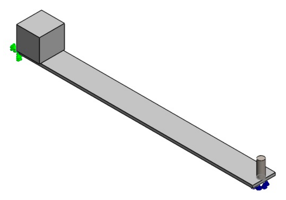
To analyse the different configurations of the system, the 3D design software SolidWorks 2023 (SP3.1 version) (SolidWorks Corp., Waltham, MA, USA) was used to model the different parts of the system, as shown in Figure 2.
The beam was modeled as a box with dimensions (450 × 34.6 × 5 mm). Its material was defined as a custom material with an elastic modulus of 71,000 N/mm2, Poisson’s ratio 0.33, tensile strength 273 N/mm2, and mass density 2800 kg/m3. The motor was modeled as a cube (44 mm edge length) and a custom material was defined with an elastic modulus of 2000 N/mm2, a Poisson’s ratio of 0.33, a tensile strength of 30 N/mm2, and a mass density of 3874 kg/m3. The accelerometer was modeled as a cylinder (12 mm diameter × 31.5 mm height). ASTM A36 steel material was assigned with an elastic modulus of 200,000 N/mm2, a Poisson’s ratio of 0.26, a tensile strength of 400 N/mm2, and a mass density of 7850 kg/m3.
The parts were assembled as shown in Figure 3. For boundary conditions, the beam was fixed at one end and free at the other. The motor was at the fixed end of the beam, while the accelerometer was at the free end. The spring was added as an “elastic support” fixture at the beam’s free end with a stiffness that varies according to the values obtained from the printed springs.
The system was meshed with “solid high-quality” mesh type and an element size of 3 mm, which results in total nodes and total elements of 30,503 and 18,322, respectively.

4. Experimental Works

4.1. Material and Methods

4.1.1. Aluminium Beam

A beam with dimensions (0.45 × 0.0436 × 0.005 m) was cut from a commercial aluminium sheet. Its mechanical properties were measured in the material laboratory at the Engineering Technical College—Baghdad, Iraq using the LARYEE Computer Control Electronic Universal Testing Machine, Model UE3450 [40]. These properties were as follows: elastic modulus 71 GPa, tensile strength 271 MPa, and yield strength 221 MPa. The mass density was found to be 2800 kg/m3.

4.1.2. Springs

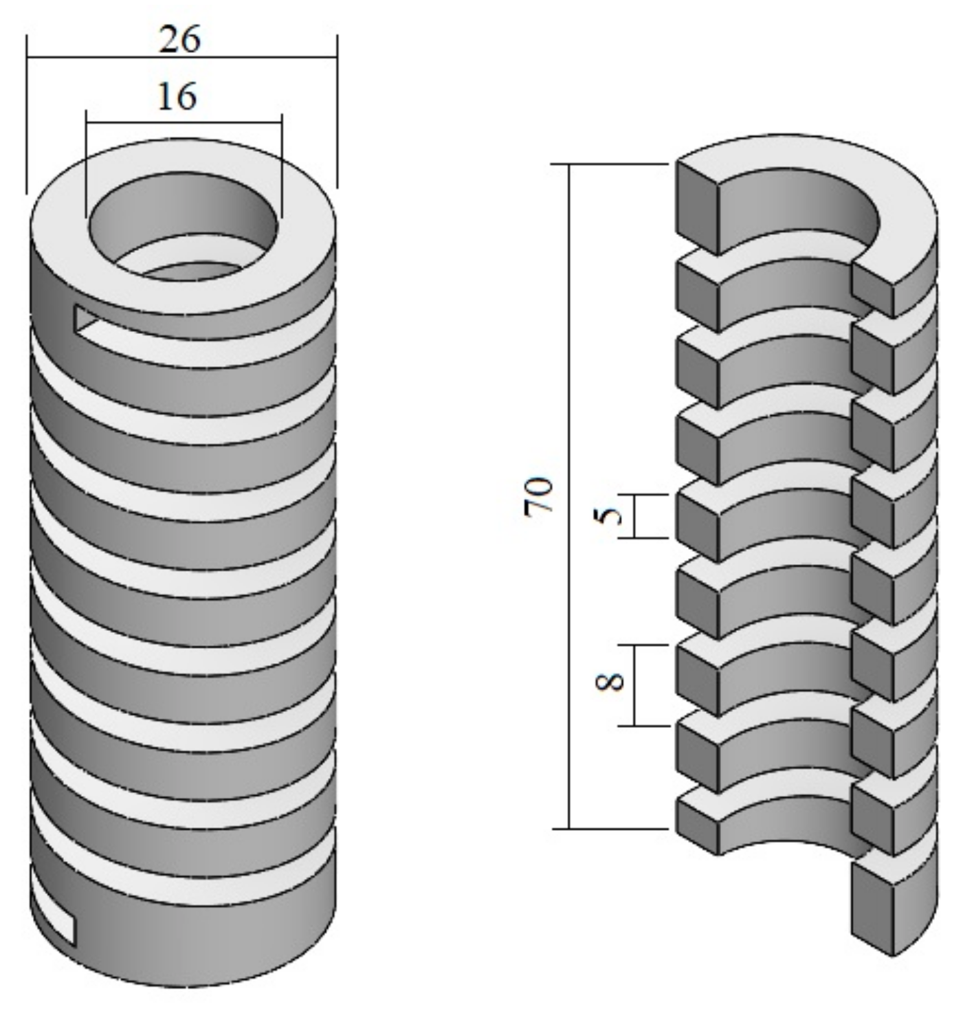
The Creality K1C 3D Printer [41] was used to print ten springs made from PLA filament. These printed springs had dimensions of 0.026 m outer diameter, 0.016 m inner diameter, and 0.07 m height. The spring contains eight active turns with a 0.008 m pitch. The rectangular cross-section was 0.005 × 0.005 m, as shown in Figure 4.
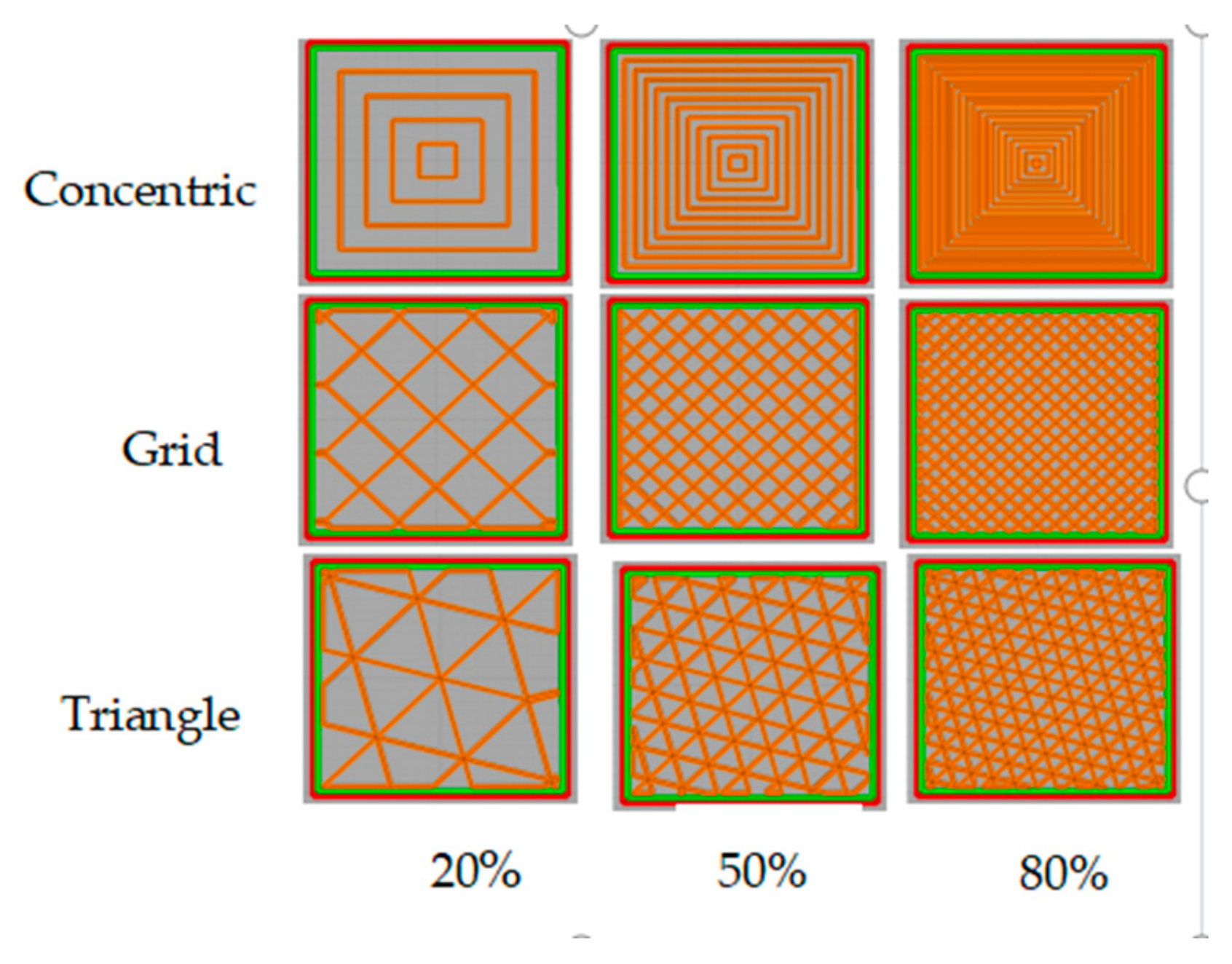
Three different infill patterns were used (concentric, grid, and triangle, which were denoted by C, G, and T symbols, respectively). For each pattern, three infill density percentages were used (20%, 50%, and 80%), as shown in Figure 5. To model the solid state, the tenth spring was printed with a triangle pattern (100% infill percentage). These three patterns were chosen because their printing lines are spaced far enough apart to show the effect of changing the infill percentage, compared with other patterns where the printing lines are close together and intertwined, making it difficult to notice the effect of changing the infill percentage of 50% or more.
The volume of each spring was 15.182 × 10⁻⁶ m3, but their mass density varies depending on the printing infill pattern and infill percentage. Therefore, the equivalent density for each spring was calculated. To obtain the equivalent density, the weight of each spring was measured in the material laboratory at the Engineering Technical College—Baghdad, Iraq using the RADWAG Model AS 220.X2 scale [42]. From the weight and volume of the springs, the equivalent density was found, and the results are listed in Table 1.
The LARYLARYEE Universal Testing Machine was also used to conduct a compression test for the printed spring specimens and obtain the (load/extension) results for each value, from which the experimental stiffness for the different springs was estimated, as listed in Table 2.
It can be noted from Table 2 that the stiffness depends on both infill percentage and infill patter, with triangle and grid patterns showing a greater effect than the concentric pattern.

4.2. Rig Setup

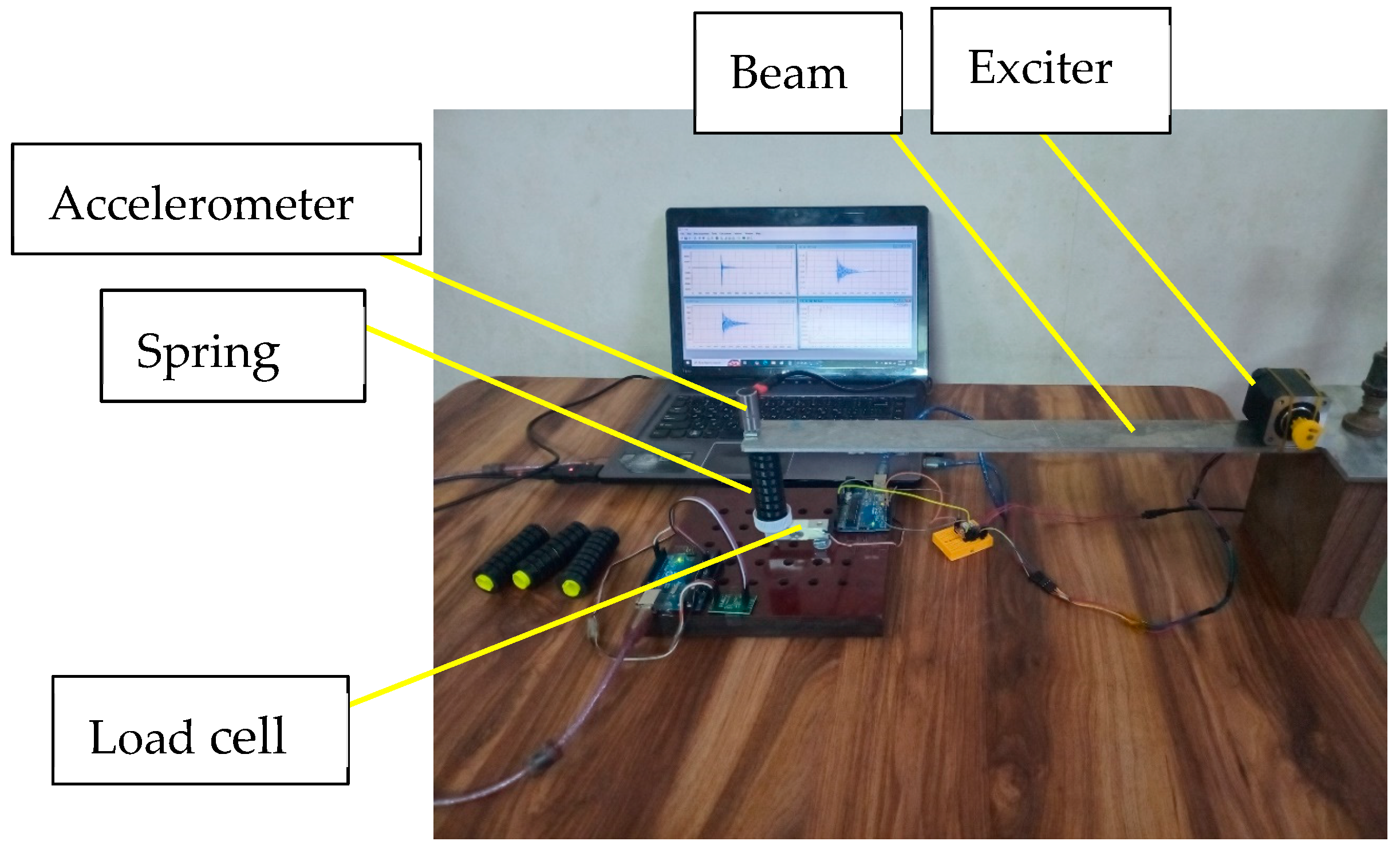
The parts attached to the aluminium cantilever beam are the accelerometer, printed spring, load cell, and stepper motor. These parts are shown in Figure 6.

4.2.1. Aluminium Cantilever Beam

As explained in Section 4.1.1.

4.2.2. Accelerometer

DigivibeMX® Version 2.1.0.4 [43] from Erbessd Instruments was used to collect and analyse the vibration data with the help of EI-CALC software 2020. The mass of the accelerometer is 0.028 kg, located at 0.01 m from the free end.

4.2.3. Printed Springs

As explained in Section 4.1.2.

4.2.4. Load Cell

A 50 kg four-wire micro load cell [44] was used to measure the applied force. The magnitude of the voltage change inside the load cell was amplified through the amplifier module and then an Arduino Uno was used to convert the numerical value into a weight value.

4.2.5. Stepper Motor

To create vibration at different frequencies, an NEMA 17 stepper motor with an A4988 driver module was used [45]. An Arduino Uno was also used to control the rotational speed of the motor. The NEMA 17 stepper motor typically has HX711 200 steps/revolution (PBC Linear company, Roscoe, IL, USA). The low and high delays for the motor were controlled by Arduino code to pulse at different times, where the step frequency fstep and the rotational speed RPM were calculated as follows:
f s t e p =   1 t o t a l   d e l a y   t i m e   =   1 High d e l a y   +   Low d e l a y   ( Hz )
The motor rotational speed can be calculated as follows:
m o t o r   s p e e d =   f s t e p     60 s t e p s   p e r   r e v o l u t i o n   ( rpm )
Vibration can be created at desired frequencies by adjusting the step frequency of the stepper motor. Three different delay times were used (1000, 750, and 500) for high and low delay in the Arduino code. The total delay per step equals the summation of the high delay and low delay. The rotational speeds were 150, 200, and 300 rpm, respectively. The mass of the motor is 0.36 kg, located at 0.022 m from the fixed end.
Figure 7 shows the arrangement of the different parts in the assembly.

5. Results

5.1. Free Vibration

For a cantilever beam without an accelerometer and by using Equation (1), the fundamental natural frequency was found to be 20.083 Hz.
When adding an accelerometer of mass 0.028 kg at the free end of the beam (the centre of mass is 0.01 m away from the free end) and using Equations (2) and (3), the theoretical, practical, and numerical (SolidWorks 2023, SP3.1 version) fundamental natural frequencies were 17.018, 17.614, and 17.119 Hz, respectively. The deviation between theoretical and practical, and between theoretical and numerical natural frequency was 0.35% and 0.59%, respectively. Adding an additional motor of mass 0.36 kg near the fixed end and using Equations (4) and (5), the theoretical, practical, and numerical fundamental natural frequencies became 17.014, 17.277, and 17.751 Hz, respectively. The deviation between theoretical and practical and between theoretical and numerical natural frequency was 1.54% and 4.33%, respectively. Installing the accelerometer near the free end results in a significant decrease in vibration value; this illustrates the importance of using Dunkerley’s approximation to calculate the frequency. Adding the mass of the motor has a negligible effect on the frequency because the mass is located near the fixed end, which acts as a supported node.
Springs with different printing parameters were used in two systems; the first system consists of an accelerometer (mass 0.028 kg) and spring at the free end of the beam. In the second system, a motor (mass 0.36 kg) is located at the fixed end. The fundamental natural frequency varies with spring stiffness, as listed in Table 3.
Adding the spring will act as an additional support to the free ends, which in turn increases the fundamental frequency. Also, it can be noted that the frequency depends on the printing parameters, as they determine the stiffness of the printed spring. Again, adding the motor has a small effect on the frequency value.

5.2. Force Measurement

The cantilever beam force variation was studied by using the load cell mentioned in Section 4.2.3 according to motor rotational speeds, infill percentages, and patterns. The resulting force was in grams, which was then converted to force in N.
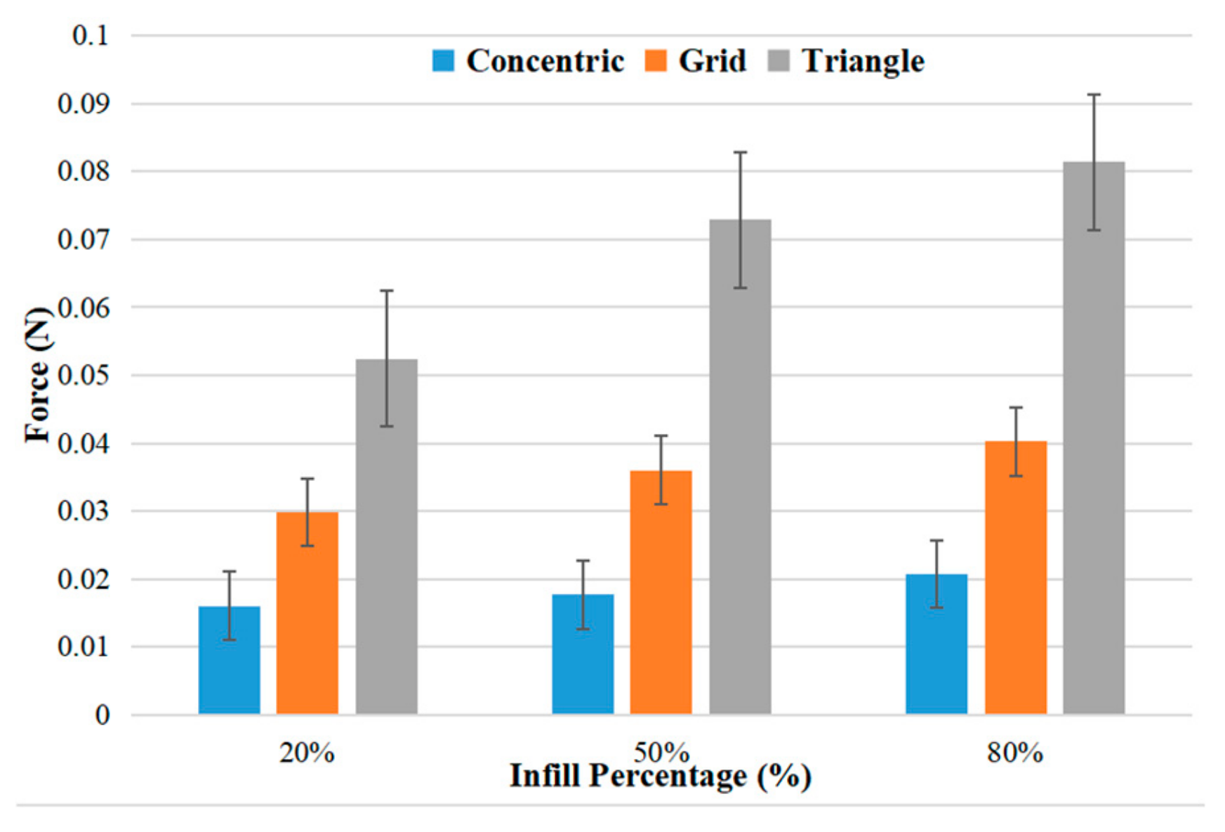
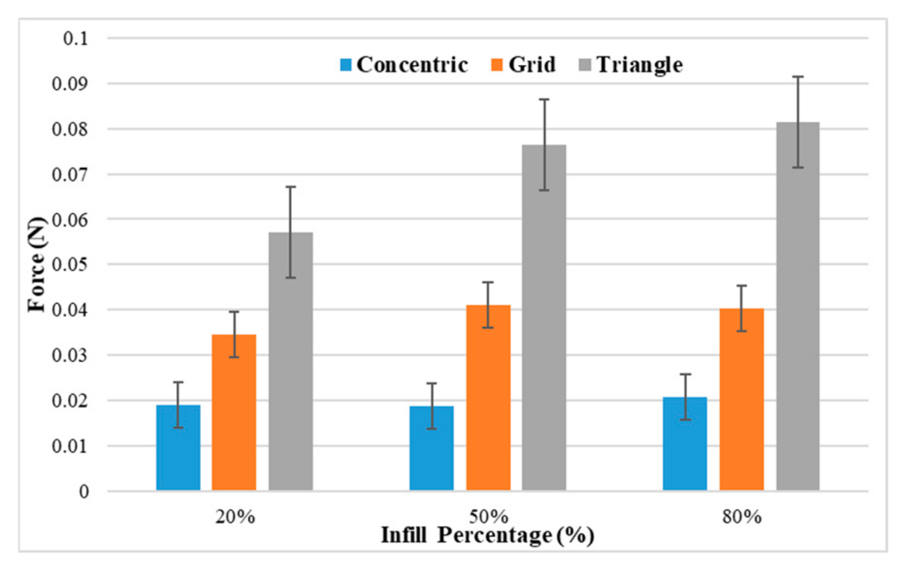
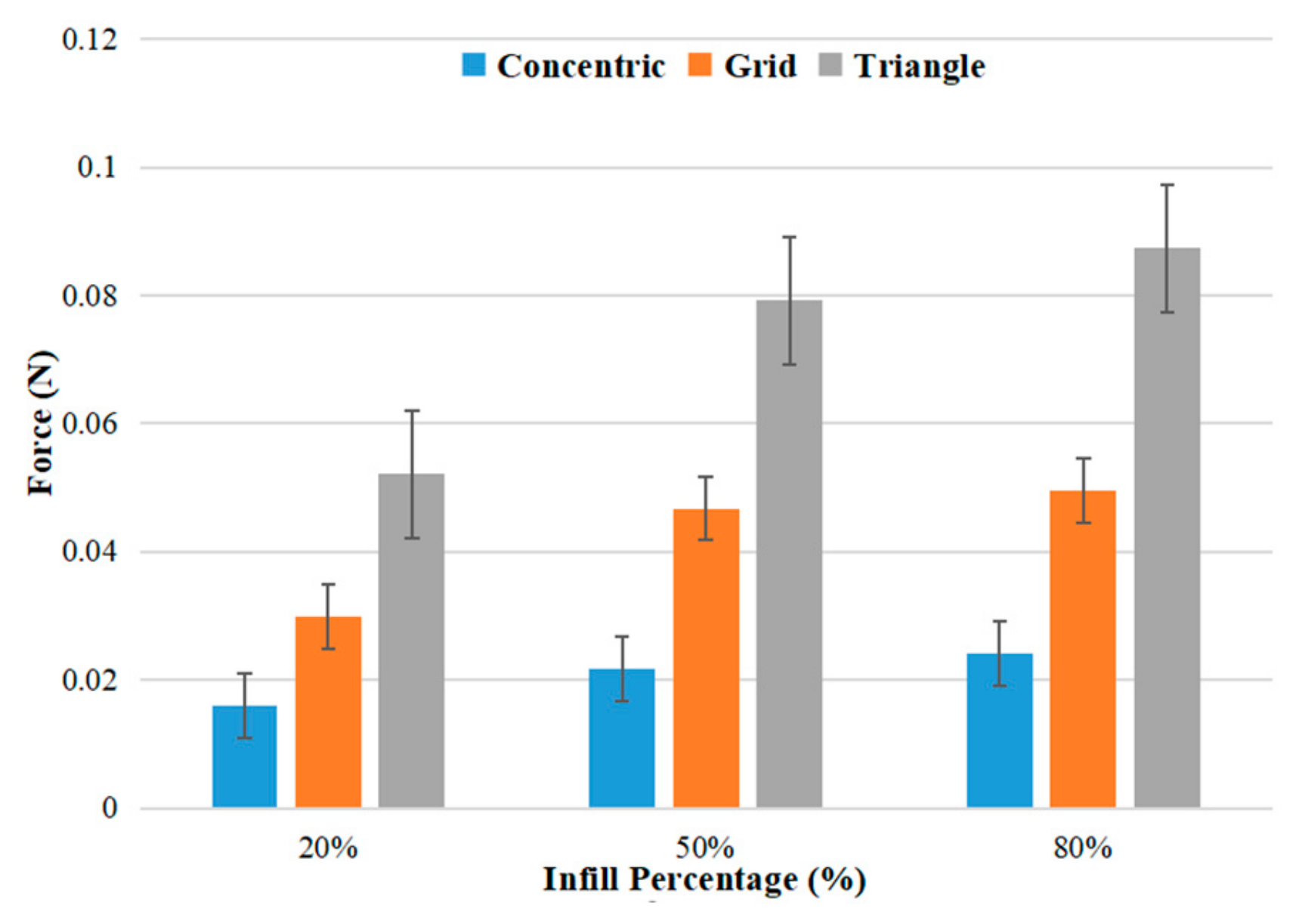
The load cell measurement signals for the cantilever beam supported by a spring printed with 20%, 50%, and 80% infill and different patterns are shown in Figure 8, Figure 9 and Figure 10.
The average force values at motor rotational speeds of 150 rpm, 200 rpm, and 300 rpm are illustrated in Table 4, Table 5 and Table 6, respectively.
It is possible to conclude that the average force is affected by changing the printing pattern more than changing the rotational speed. Also, increasing the infill percentage slightly increases the resulting force.
The average force signals for the cantilever beam supported by a spring printed with a 100% infill triangle pattern are shown in Figure 11 The average force values were 0.023, 0.041, and 0.078 N at motor rotational speeds of 150, 200, and 300 rpm, respectively. Increasing the rotational speed increases the average force.

6. Discussions

  • The motor has a dynamic effect which causes beam vibration. Increasing the rotational speed causes the motor to exert more energy into the beam at a specific time. For the “grid” pattern at 50% infill percentage, increasing the rotational speed from 150 to 300 rpm increases the resulting force from 0.036 N to 0.047 N, which means an increase in force by 30%.
  • When the motor rotates, the excitation force is small and the vibration resulting from it is far from the resonance value; therefore, the beam properties can be modified so that the fundamental natural frequency can be lowered to be close to the motor frequency.
  • The “triangle” printing pattern results in the highest force. It creates a “truss-like” structure which is efficient for carrying loads because the resulting forces act as axial tension along the filament lines. The “grid” pattern, which is composed of square shapes, is less efficient because these shapes are deformed by filament bending at the joints, which results in less stiffness and resulting force. The “concentric” pattern shows the lowest force because this pattern acts as multiple unsupported rings, which have the lowest stiffness and resulting force. At 80% infill and 300 rpm, the force resulting from the “triangle” pattern was 0.087 N, which is 3.6 times greater than the force of the “concentric” pattern (0.024 N).
  • For the “triangle” pattern at a rotational speed of 150 rpm, increasing the infill percentage from 20% to 80% increases the force from 0.052 N to 0.081 N, which means an increase of 56%.
  • The “triangle” pattern with 80% infill density is recommended for printing when compared with 100% infill density because the difference in results is very small; this reduces cost and weight when using 80% infill density.
  • This system can be used to harvest electrical signals resulting from the vibration of the beam if a piezoelectric sensor is mounted under the spring.
  • There was a slight difference between theoretical and experimental results of natural frequency, which may arise due to clamping conditions or effective stiffness of the spring.

7. Conclusions

  • The stiffness of a printed spring is not just a material property; it is also affected by its internal geometry, which is defined by the printing pattern.
  • The printing pattern is the most powerful factor affecting the printed spring stiffness, while infill percentage is used for fine-tuning the spring stiffness.
  • Increasing the infill percentage means more printing material within the same volume, which increases spring stiffness.
  • The stepper motor can be replaced by an electrical DC motor to obtain higher rotational speed. Also, an eccentric mass can be attached to this motor to control the value of the excitation vibration.

8. Future Works

  • It is suggested to perform the study using other different printing patterns to find out the best pattern to use.
  • Adding a piezoelectric sensor under the spring to harvest electrical signals resulting from beam vibration.

Author Contributions

Conceptualisation, H.H.M. and S.A.N.; methodology, H.H.M. and S.A.N.; software, S.A.N.; validation, H.H.M., S.A.N., M.T.M. and T.T.; formal analysis, H.H.M., S.A.N., M.T.M. and T.T.; investigation, H.H.M., S.A.N., M.T.M. and T.T.; resources, H.H.M., S.A.N., M.T.M. and T.T.; data curation, H.H.M., S.A.N., M.T.M. and T.T.; writing—original draft preparation, H.H.M. and S.A.N.; writing—review and editing, H.H.M., S.A.N., M.T.M. and T.T.; visualisation, H.H.M., S.A.N., M.T.M. and T.T.; supervision, H.H.M. and S.A.N.; project administration, H.H.M. and S.A.N.; funding acquisition, H.H.M., S.A.N., M.T.M. and T.T. All authors have read and agreed to the published version of the manuscript.

Funding

This research received no external funding.

Institutional Review Board Statement

Not applicable.

Informed Consent Statement

Not applicable.

Data Availability Statement

Data are contained within the article.

Acknowledgments

The research reported in this paper was supported by the Middle Technical University, Engineering Technical College/Baghdad: Applied Engineering Department.

Conflicts of Interest

The authors declare no conflicts of interest.

References

  1. Zannon, M. Free Vibration of Thin Film Cantilever Beam. Int. J. Eng. Tech. Res. (IJETR) 2014, 2, 304–316. [Google Scholar]
  2. Singh, S.; Singh, A. Free Vibration Analysis on cantilever beam—A review. Int. Res. J. Eng. Technol. (IRJET) 2017, 4, 1449–1452. [Google Scholar]
  3. Mia, S.; Islam, S.; Ghosh, U. Modal Analysis of Cracked Cantilever Beam by Finite Element Simulation. Procedia Eng. 2017, 194, 509–516. [Google Scholar] [CrossRef]
  4. Zheng, Y.; Yang, Y.; Wu, R.-J.; He, C.-Y.; Guang, C.-H. Dynamic Analysis of a Hybrid Compliant Mechanism with Flexible Central Chain and Cantilever Beam. Mech. Mach. Theory 2021, 155, 104095. [Google Scholar] [CrossRef]
  5. Lei, X.; Wang, Y.; Wang, X.; Lin, G.; Shi, S. Revisited on the Free Vibration of a Cantilever Beam with An Asymmetrically Attached Tip Mass. Math. Probl. Eng. 2021, 2021, 8024879. [Google Scholar] [CrossRef]
  6. Ahiwale, D.; Madake, H.; Phadtare, N.; Jarande, A.; Jambhale, D. Modal Analysis of Cracked Cantilever Beam Using ANSYS Software. Mater. Today Proc. 2022, 56, 165–170. [Google Scholar] [CrossRef]
  7. Ali, M.S. Vibration Analysis and Modelling of a Cantilever Beam; Technical Report No.381312144; ResearchGate: Berlin, Germany, 2024. [Google Scholar]
  8. Herisanu, N.; Marinca, B.; Marinca, V. Nonlinear Dynamics of an Electromagnetically Actuated Cantilever Beam Under Harmonic External Excitation. Appl. Sci. 2024, 14, 10335. [Google Scholar] [CrossRef]
  9. Skerys, P.; Gaidys, R. A Dynamic Analysis of a Cantilever Piezoelectric Vibration Energy Harvester with Maximized Electric Polarization Due to the Optimal Shape of the Thickness for First Eigen Frequency. Appl. Sci. 2025, 15, 7525. [Google Scholar] [CrossRef]
  10. Despotović, Ž.V.; Lecic, M.; Jovic, M.; Djuric, A. Vibration Control of Resonant Vibratory Feeders with Electromagnetic Excitation. FME Trans. 2014, 4, 281–289. [Google Scholar] [CrossRef]
  11. Chandravanshi, M.L.; Mukhopadhyay, A.K. Dynamic Analysis of Vibratory Feeder and Their Effect on Feed Particle Speed on Conveying Surface. Measurement 2017, 101, 145–156. [Google Scholar] [CrossRef]
  12. Vellingiri, V.; Sadasivam, U. Effect of Vibrator Parameters and Physical Characteristics of Parts on Conveying Velocity. Stroj. Vestn.-J. Mech. Eng. 2023, 69, 352–363. [Google Scholar] [CrossRef]
  13. Fragassa, C.; Pavlovic, A.; Berardi, L.; Vitali, G. Investigating the Dynamic Behavior of a Linear Vibratory Feeder. Proc. Eng. Sci. 2023, 5, 495–502. [Google Scholar] [CrossRef]
  14. Yadav, A.; Singh, N.K. Effects of Accelerometer Mass on Natural Frequency of a Magnesium Alloy Cantilever Beam. Vibroeng. Procedia 2019, 29, 207–212. [Google Scholar] [CrossRef]
  15. Mereles, A.; Varanis, M.; Silva, A.; Balthazar, J.; Lopes, E.; Bavastri, C. Mathematical Modelling of a Cantilever Beam Driven by two Unbalanced Eletric Motors. In Proceedings of the 25th ABCM International Congress on Mechanical Engineering (COBEM 2019), Uberlândia, MG, Brazil, 20–25 October 2019. [Google Scholar] [CrossRef]
  16. Guo, G.; Zhong, S.; Zhang, Q.; Zhong, J.; Liu, D. Effect of Additional Mass on Natural Frequencies of Weight-Sensing Structures. Sensors 2023, 23, 7585. [Google Scholar] [CrossRef]
  17. Rossit, C.A.; Laura, P.A.A. Free Vibrations of a Cantilever Beam with a Spring–Mass System Attached to the Free End. Ocean Eng. 2001, 28, 933–939. [Google Scholar] [CrossRef]
  18. Jafari, M.; Djojodihardjo, H.; Ahmad, K. Vibration Analysis of a Cantilevered Beam with Spring Loading at the Tip as a Generic Elastic Structure. Appl. Mech. Mater. 2014, 629, 407–413. [Google Scholar] [CrossRef]
  19. Aydin, E. Minimum Dynamic Response of Cantilever Beams Supported by Optimal Elastic Springs. Struct. Eng. Mech. 2014, 51, 377–402. [Google Scholar] [CrossRef]
  20. Chang, J.-R.; Tu, T.-W.; Huang, C.J. An Analytic Solution for the Dynamic Behavior of a Cantilever Beam with a Time-Dependent Spring-Like Actuator. Axioms 2023, 12, 500. [Google Scholar] [CrossRef]
  21. Boisseau, S.; Despesse, G.; Ricart, T.; Defay, E.; Sylvestre, A. Cantilever-Based Electret Energy Harvesters. Smart Mater. Struct. 2011, 20, 105013. [Google Scholar] [CrossRef]
  22. Yao, F.; Meng, W.; Zhao, J.; Yin, H. Cantilever Beam Based Piezoelectric Energy Harvester. Int. J. Smart Sens. Intell. Syst. 2015, 8, 2018–2041. [Google Scholar] [CrossRef]
  23. Karpinski, P.; Ambrozkiewicz, B.; Czyż, Z.; Litak, G. Performance Analysis of Piezoelectric Energy Harvesting System Under Varying Bluff Body Masses and Diameters—Experimental Study and Validation with 0–1 Test. Appl. Sci. 2025, 15, 6972. [Google Scholar] [CrossRef]
  24. Atmajaya, A.; Jatisukamto, G.; Triono, A.; Syuhri, S. Add-On Energy Harvesting System Using Cantilever Beam in an Engine Mount. AIP Conf. Proc. 2020, 2278, 020015. [Google Scholar] [CrossRef]
  25. Tuma, C.; Phaoharuhansa, D. Vibration Energy Harvest for Low Frequency Using Double-Piezoelectric Cantilever Beam. In Proceedings of the 6th International Conference on Mechatronics and Mechanical Engineering (ICMME 2019), Osaka, Japan, 27–30 November 2019; Volume 306, p. 04006. [Google Scholar] [CrossRef]
  26. Xu, Q.; Gao, A.; Li, Y.; Jin, Y. Design and Optimization of Piezoelectric Cantilever Beam Vibration Energy Harvester. Micromachines 2022, 13, 675. [Google Scholar] [CrossRef] [PubMed]
  27. Chen, L.; Zhang, M.; Xu, Z.; Chen, H.; Xu, J. A Multiple-Cantilever Piezoelectric Vibration Energy Harvester for Self-Powered CO2 Monitoring in Transformer Substations. Appl. Sci. 2024, 14, 10805. [Google Scholar] [CrossRef]
  28. Nisanth, A.; Suja, K.; Seena, V. A Novel Design Strategy for Cantilever Based MEMS Piezoelectric Vibration Energy Harvesters: FEM Parametric Analysis and Modeling. e-Prime-Adv. Electr. Eng. Electron. Energy 2024, 9, 100724. [Google Scholar] [CrossRef]
  29. He, L.; Peng, H.; Lin, M.; Konjeti, R.; Guimbretiere, F.; Froehlich, J. Designing and Controlling 3D Printable Springs. In Proceedings of the 32nd Annual ACM Symposium on User Interface Software and Technology, New Orleans, LA, USA, 20–23 October 2019; pp. 739–750. [Google Scholar] [CrossRef]
  30. Dalaq, A.S.; Daqaq, M.F. Experimentally-Validated Computational Modeling and Characterization of the Quasi-Static Behavior of Functional 3D-Printed Origami-Inspired Springs. Mater. Des. 2022, 216, 110541. [Google Scholar] [CrossRef]
  31. Mahdi, H.H.; Nama, S.A.; Khazaal, S.M. Experimental and Numerical Investigation on the Free Vibration Characteristics of 3D Printed Springs with Square Cross Sections. Math. Model. Eng. Probl. 2023, 10, 1961–1966. [Google Scholar] [CrossRef]
  32. Yang, Z.; He, F.; Khan, M. An Empirical Torsional Spring Model for the Inclined Crack in a 3D-Printed Acrylonitrile Butadiene Styrene (ABS) Cantilever Beam. Polymers 2023, 15, 496. [Google Scholar] [CrossRef]
  33. Kim, T.-H.; Moeinnia, H.; Kim, W.S. 3D Printed Vorticella-Kirigami Inspired Sensors for Structural Health Monitoring in Internet-of-Things. Mater. Des. 2023, 234, 112332. [Google Scholar] [CrossRef]
  34. He, F.; Ning, H.; Khan, M. Effect of 3D Printing Process Parameters on Damping Characteristic of Cantilever Beams Fabricated Using Material Extrusion. Polymers 2023, 15, 257. [Google Scholar] [CrossRef]
  35. Bakhtiari, H.; Aamir, M.; Tolouei-Rad, M. Effect of 3D Printing Parameters on the Fatigue Properties of Parts Manufactured by Fused Filament Fabrication: A Review. Appl. Sci. 2023, 13, 904. [Google Scholar] [CrossRef]
  36. Jasinski, K.; Murawski, L.; Kluczyk, M.; Wierzchowski, J.; Chodnicki, M.; Lipinski, K.; Szelezinski, A. Analysis of the Possibility of Using 3D Printing for Emergency Replacement of Damaged Elements in the Marine Industry. Appl. Sci. 2025, 15, 3458. [Google Scholar] [CrossRef]
  37. Chatpun, S.; Dissaneewate, T.; Kwanyuang, A.; Nouman, M.; Srewaradachpisal, S.; Movrin, D. Infill Pattern and Density of 3D-Printed Insoles Alter Energy and Pressure Distribution in Gait. Appl. Sci. 2025, 15, 3916. [Google Scholar] [CrossRef]
  38. Daniel, J. Inman: Engineering Vibrations, 4th ed.; Pearson Education Inc.: London, UK, 2013; pp. 46–52. [Google Scholar]
  39. Singiresu, S. Rao: Mechanical Vibrations; Pearson Education Inc.: London, UK, 2018; p. 702. [Google Scholar]
  40. Computer Control Electronic Universal Testing Machine. Available online: https://www.laryee.com/Electronic-utm (accessed on 10 June 2025).
  41. Carbon Fiber 3D printing. Creality’s Official Website. Available online: https://www.creality.com/products/k1c-carbon-3d-printer?spm=..product_fc547c47-66f3-4ee3-a06c-e06eaa83904d.header%201.1 (accessed on 3 June 2025).
  42. New Weighting Modules. Available online: https://radwag.com/en/ (accessed on 30 June 2025).
  43. Vibration Measuring Instruments. Available online: https://www.erbessd-instruments.com/digivibe/ (accessed on 10 August 2025).
  44. Micro Load Cell. Available online: https://www.robotshop.com/products/micro-load-cell-50-kg (accessed on 6 July 2025).
  45. Steeper Motor. Available online: https://us.openbuilds.com/nema-17-stepper-motor/ (accessed on 6 July 2025).
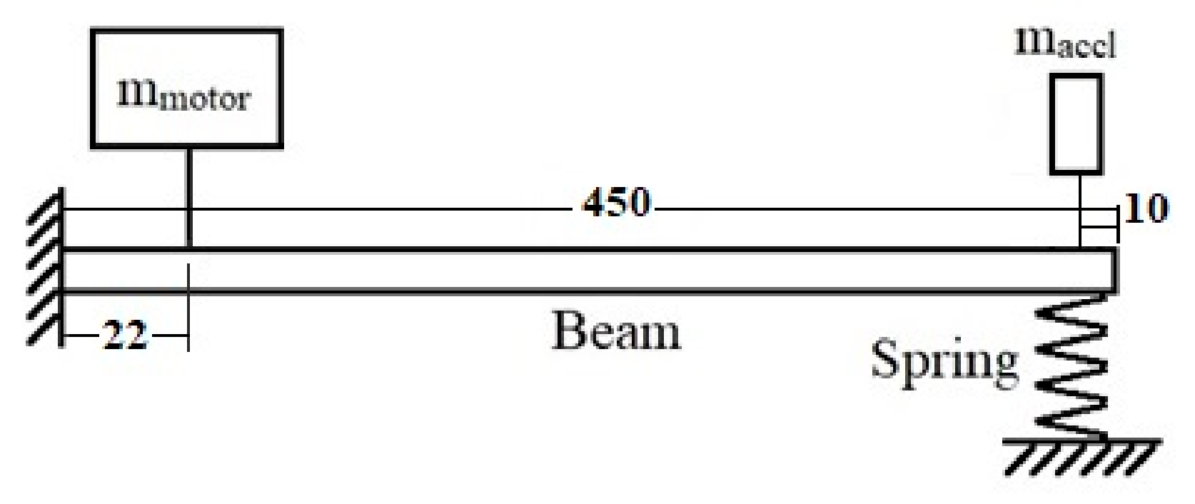
Figure 1. Cantilever beam system with two masses and a spring (dimensions in mm).
Applsci 15 12344 g001
Figure 2. The beam, motor, and accelerometer parts modeled in SolidWorks.
Applsci 15 12344 g002
Figure 3. System assembly modelled in SolidWorks.
Applsci 15 12344 g003
Figure 4. Printed spring samples (dimensions in mm).
Applsci 15 12344 g004
Figure 5. Infill patterns and infill percentages for the printed springs.
Applsci 15 12344 g005
Figure 6. Accelerometer, printed spring, load cell, and NEMA 17 motor.
Applsci 15 12344 g006
Figure 7. Vibration test analysis setup.
Applsci 15 12344 g007
Figure 8. Load cell reading at 150 rpm rotational speed.
Applsci 15 12344 g008
Figure 9. Load cell reading at 200 rpm rotational speed.
Applsci 15 12344 g009
Figure 10. Load cell reading at 300 rpm rotational speed.
Applsci 15 12344 g010
Figure 11. Load cell signal for 100% infill and different rotational speeds.
Applsci 15 12344 g011
Table 1. Spring–mass and equivalent density for different patterns at different infill %.
Infill %ConcentricGridTriangle
Weight
×10−3 (kg)
Density
(kg/m3)
Weight
×10−3 (kg)
Density
(kg/m3)
Weight
×10−3 (kg)
Density
(kg/m3)
2010.773709.62513.299876.01515.181999.984
5011.301744.40513.739905.05116.0151054.92
8011.455754.54914.109929.3716.1371062.96
100--------------------17.6771164.4
Table 2. Spring stiffness for different patterns at different infill %.
Infill %Spring Stiffness (N/m)
ConcentricGridTriangle
20893.4964.21123
50123612431339.2
801379.11481.71503.8
100------------1558.4
Table 3. Fundamental natural frequencies for two systems.
Infill %
and Infill Pattern
Stiffness (N/m)Accelerometer–Spring SystemAccelerometer–Spring–Motor System
Practical (Hz)Theoretical (Hz)Deviation
%
Numerical
(Hz)
Deviation
%
Practical (Hz)Theoretical (Hz)Deviation
%
Numerical
(Hz)
Deviation
%
20C893.423.04723.1070.2622.7181.6823.22223.3840.6922.6623.09
50C123624.62425.0501.7024.5052.1824.39224.3940.0124.4350.17
80C1379.124.89725.8183.5725.212.3524.56524.6850.4925.1361.83
20G964.223.55323.5220.1323.0991.8023.21623.2160.0023.040.76
50G124324.67625.0881.6424.542.1824.23024.3910.6624.470.32
80G1481.725.29726.3554.0125.7022.4825.23725.4040.6625.6260.87
20T112323.83024.4262.4423.9312.0323.55323.4960.2423.8661.57
50T1339.225.01125.6062.3225.0162.3024.56124.5620.0024.9421.55
80T1503.825.45926.4703.8225.8072.5024.90024.9000.0025.733.33
100T1558.425.91426.7503.1326.0642.5625.90825.9080.0025.9850.30
Table 4. Force measurement due to 150 rpm rotational speed.
Infill
%
Force (N)
ConcentricGridTriangle
200.0160.030.052
500.0180.0360.072
800.0210.040.081
Table 5. Force measurement due to 200 rpm rotational speed.
Infill
%
Force (N)
ConcentricGridTriangle
200.0190.0350.056
500.0190.0410.076
800.0230.0430.082
Table 6. Force measurement due to 300 rpm rotational speed.
Infill
%
Force (N)
ConcentricGridTriangle
200.0210.0410.061
500.0220.0470.079
800.0240.0490.087
Disclaimer/Publisher’s Note: The statements, opinions and data contained in all publications are solely those of the individual author(s) and contributor(s) and not of MDPI and/or the editor(s). MDPI and/or the editor(s) disclaim responsibility for any injury to people or property resulting from any ideas, methods, instructions or products referred to in the content.