1. Introduction
As a revolutionary approach for astronomical observation, gravitational wave detection has opened new windows for studying compact objects, galactic evolution, and cosmic structure. The low-frequency band (1 mHz–0.1 Hz) of space-based gravitational waves carries rich information about supermassive black hole mergers and compact binary systems, which remains undetectable using ground-based short-arm interferometers [
1,
2,
3,
4,
5] due to their limited sensitivity in this frequency range. To overcome this limitation, several space missions proposing ultra-long-baseline space laser interferometers with arm lengths ranging from hundreds of thousands to millions of kilometers have been initiated worldwide, including the Laser Interferometer Space Antenna (LISA) project [
6,
7], as well as China’s proposed Taiji [
8] and TianQin [
9] programs.
The detectors for these missions typically consist of a constellation of three spacecraft forming an equilateral triangle, with arm lengths ranging from several hundred thousand to millions of kilometers between each pair. Each pair of arms forms a Michelson interferometer, and the six-laser links between the three spacecraft establish bidirectional communication channels. Picometer-level relative distance variations between spacecraft induced by gravitational waves are measured using laser heterodyne interferometry. Ultimately, the gravitational wave strain signal is extracted from all interferometric signals through post-processing on the ground using the Time-Delay Interferometry (TDI) algorithm.
For ground-based laser interferometers with strictly equal arms, effective common-mode suppression of laser frequency noise can be achieved. However, due to orbital motion and unavoidable perturbations from other celestial bodies, the inter-satellite distances in space-based interferometers continuously vary, with the annual relative change in arm length reaching up to ±1%. The significant arm length mismatch causes laser frequency noise to become the dominant noise source in the interferometric measurement system [
6]. The TDI algorithm addresses this by time-shifting the measurement data from the three spacecraft and recombining it to synthesize a virtual equal-arm interferometer, thereby suppressing laser frequency noise. The precision of the time-shifting process in the TDI data combination depends on the accuracy of the inter-satellite absolute ranging. Assuming the laser frequency noise can be reduced to
after pre-stabilization, with a relative displacement measurement precision of
and a laser wavelength of 1064 nm, the required accuracy for the inter-satellite absolute distance measurement is calculated to be at the meter level [
10,
11]. Furthermore, one of the three spacecraft serves as the master spacecraft for communication with Earth, while the other two subordinate spacecraft must transmit their measurement data to the master via inter-satellite links. Taking LISA as an example, the expected data volume to be transmitted between satellites is greater than 15kbps [
11]. Therefore, in addition to the primary task of relative distance measurement, the inter-satellite laser links must also fulfill two auxiliary functions: inter-satellite absolute ranging and inter-satellite communication.
The LISA team first proposed an inter-satellite ranging and communication scheme, achieving a ranging accuracy of 42 cm at a 3 Hz output rate with a received optical power of 100 pW [
11], while simultaneously transmitting communication data at 24 kbps. No bit errors were detected when Forward Error Correction (FEC) with Reed–Solomon (RS) codes was applied. In 2018, Nils Brause et al. [
12] reported achieving a communication data rate of b = 78.125 kbps under a high carrier-to-noise ratio (CNR) of 75 dBHz, with a Bit Error Rate (BER) of 100 μbits
−1 without using FEC. Subsequent LISA research integrated PRN code ranging with TDI ranging calibration, achieving ranging accuracies between 2.0 cm and 8.1 cm [
13]. China’s Taiji and TianQin teams have also conducted preliminary studies and validations using similar schemes. The Institute of Mechanics, Chinese Academy of Sciences, conducted an electronic verification for inter-satellite ranging within the context of the Taiji program [
14]. Using a 50 MHz sampling frequency and a 1.5625 Mbps 1024-bit Weil code, they achieved a ranging accuracy better than 1.6 m. Sun Yat-sen University [
15] also reported a bidirectional laser PRN code ranging system for the TianQin mission. Utilizing a 3.125 Mbps PRN code with phase modulation on the laser sidebands, they performed a bidirectional ranging verification experiment over a 10 km optical fiber, ultimately achieving a laser ranging accuracy of 1.2 m.
In summary, the LISA consortium has successfully validated the feasibility of its laser ranging and communication scheme through theoretical analysis and ground-based experiments, with performance metrics meeting design specifications. The Taiji and TianQin teams in China have also conducted preliminary validations of their respective schemes. However, a significant gap remains between the conceptual principle and a fully validated, stable technological platform. Enhancements are still required in terms of ranging accuracy and the maturity of the integrated ranging-communication architecture. Under the premise of excluding clock offset considerations, this paper presents a concrete implementation scheme for unidirectional integrated ranging and communication within the context of space-based gravitational wave detection. The detailed algorithmic workflow is elaborated, and a comprehensive desktop experimental setup—progressing from electronic verification to high signal-to-noise ratio optical experiments—is established to demonstrate the functional correctness of the algorithms, thereby establishing a functionally sound and architecturally well-defined technical baseline.
2. Principles and Key Algorithms
This section presents the inter-satellite ranging principles within the context of space-based gravitational wave detection. It subsequently provides a detailed description of the PRN code synchronization algorithm—a crucial component of the ranging receiver system—including both code acquisition and tracking, along with the implementation methodology for integrating ranging and communication functions.
As auxiliary functions for space-based laser interferometric gravitational wave detection missions, both inter-satellite absolute distance measurement and communication capabilities must not only be functionally effective but also minimize their impact on the inter-satellite laser interferometric displacement measurements. To this end, approximately 1% of the total received optical power is allocated for inter-satellite ranging and communication [
16]. Given the million-kilometer inter-satellite distances and the use of continuous-wave lasers with a wavelength of 1064 nm, employing the highly precise delta pseudo-ranges measurement method used in GPS [
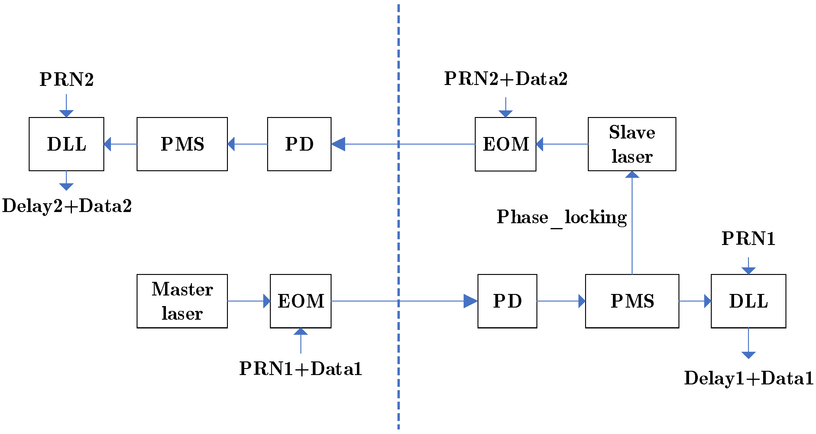
17] would lead to a wavelength integer ambiguity problem. The spread-spectrum communication technique based on PRN code sequences, proposed by LISA, can overcome this ambiguity while integrating ranging and communication functions. Here, the PRN code serves as both the spread-spectrum code and the ranging code. A simplified schematic diagram of the integrated inter-satellite laser ranging and communication scheme within the context of space-based gravitational wave detection is shown in
Figure 1.
Figure 1 illustrates a system capable of bidirectional inter-satellite ranging and communication, where the two satellites utilize PRN1 code and PRN2 code as their respective ranging codes [
18]. Since the bidirectional ranging and communication process is symmetrical, this paper focuses specifically on a detailed study of the unidirectional integrated ranging and communication scheme.
The master and follower spacecraft feature symmetric configurations: their respective PRN codes (PRN1, PRN2) and communication data (Data1, Data2) are phase-modulated onto the laser beams via Electro-Optic Modulators (EOMs) and transmitted to the remote spacecraft. The received laser light interferes with the local laser at the Photodetector (PD). The Phase Measurement System (PMS) accomplishes weak-light phase locking of the local laser and performs carrier stripping for PRN code ranging. The Delay Lock Loop (DLL) achieves PRN code synchronization to determine the time delay, subsequently enabling the recovery of the received data information.
The expected output signal [
11] from the photodetector can be expressed as:
where
represents the heterodyne efficiency,
and
denote the available optical power of the received beam and local oscillator beam before interference, respectively.
signifies the shot noise at the detector output.
corresponds to the angular heterodyne frequency of the carrier beat note, which ranges from 5 MHz to 25 MHz [
19].
represents the phase of the beat note, given by:
where
represents the phase containing scientific information and residual phase noise, which is distinct from the high-rate PRN code phase.
denotes the phase modulation coefficient for the ranging PRN code, and
represents the composite code formed by the ranging PRN code and the communication data code.
will be tracked and locked by the Digital Phase-Locked Loop (DPLL) within the Phase Measurement System [
19], simultaneously enabling the stripping of both the composite code and the carrier. The error signal from the DPLL is subsequently utilized as the input signal for the Delay Lock Loop (DLL). According to the PRN code ranging principle, the local receiver generates a replica PRN code identical to that of the transmitter. The time delay of the PRN code is determined by analyzing the correlation between the locally generated PRN code and the received PRN code [
20]. This measured time delay, combined with the speed of light, provides the absolute inter-satellite distance information.
During the PRN code acquisition phase, while conventional approaches predominantly employ threshold detection methods, this paper adopts a resource-efficient sliding correlation method [
21,
22] combined with a distributed two-stage integrator to mitigate interference from communication codes. The sliding window is set to one chip width to identify the peak correlation point, providing greater accuracy compared to the threshold detection method [
14]. The acquisition result is directly fed into the tracking loop, thereby confining the tracking range within a single chip period. Since data encoding effectively acts as noise interference for PRN code ranging [
11], this creates a mutual constraint between the ranging and communication functions.
For the selection of the PRN code, this work employs the 1024-chip PRN sequence utilized by LISA, as referenced in Dr. Brause’s dissertation [
12]. A key distinction in our implementation is that the actual PRN code used is pre-processed by applying Manchester encoding to the original 1024-chip sequence. This enhancement improves robustness by mitigating the filtering effect of the DPLL on the PRN code [
11]. The Manchester encoding process subsequently doubles the code length to 2048 chips. With a system clock rate set at 80 MHz, each PRN code chip corresponds to 32 clock cycles, resulting in a chipping rate of approximately 2.50 MHz. Furthermore, to meet the communication data rate requirement of no less than 15 kbps, this study sets the operational data rate at 39 kbps, which corresponds to a spreading factor of 64.
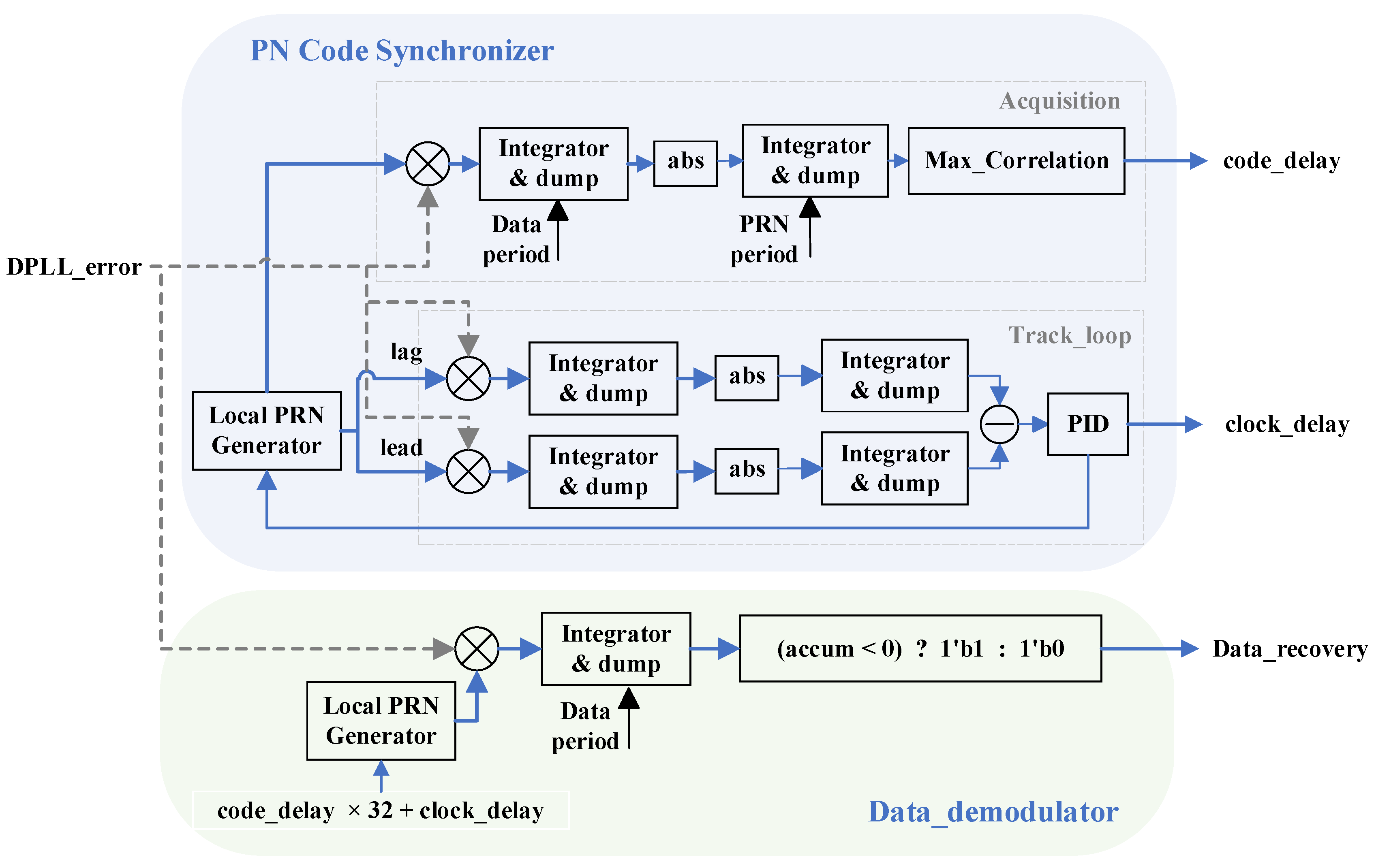
Algorithm optimization is implemented to mitigate the impact of data encoding on ranging performance. During the correlation operations for PRN code acquisition and tracking, the process employs two correlators, performing integration first within each data period (64 chip periods) and subsequently across the entire PRN sequence (2048 chip periods). This approach enables the mutual compatibility and integration of ranging and communication functions. The schematic structure of the DLL is illustrated in
Figure 2. During the acquisition phase, the received data code can be recovered directly from the first-stage integration results. Following successful acquisition, loop tracking is maintained using an early–late gate [
23] combined with a PID controller [
24,
25]. The final PRN code offset address is utilized for data decoding. Throughout both acquisition and tracking processes, the calculation of integration results and the updating of addresses are performed concurrently. The simplified block diagram of the DLL structure is shown in
Figure 2.
PRN code synchronization is divided into two phases: acquisition and tracking. The system comprises three parallel branches, each utilizing a two-stage integrator. The Delay Lock Loop (DLL) tracking loop maintains stability by generating an error signal from the difference between the early and late branches, which is then processed by a PID controller. The acquisition result , represents the delayed PRN sequence in number of chips, while the tracking result , denotes the delay in clock cycles. Data decoding is performed after the completion of PRN code synchronization.
Upon obtaining the PRN code acquisition result and the tracking result , the signals are decimated to 3–10 Hz using a CIC filter before being transmitted to a computer for data post-processing.
Let
denote one clock cycle period, and
represent the number of clock cycles corresponding to one chip. The absolute distance is then given by:
where
is the speed of light.
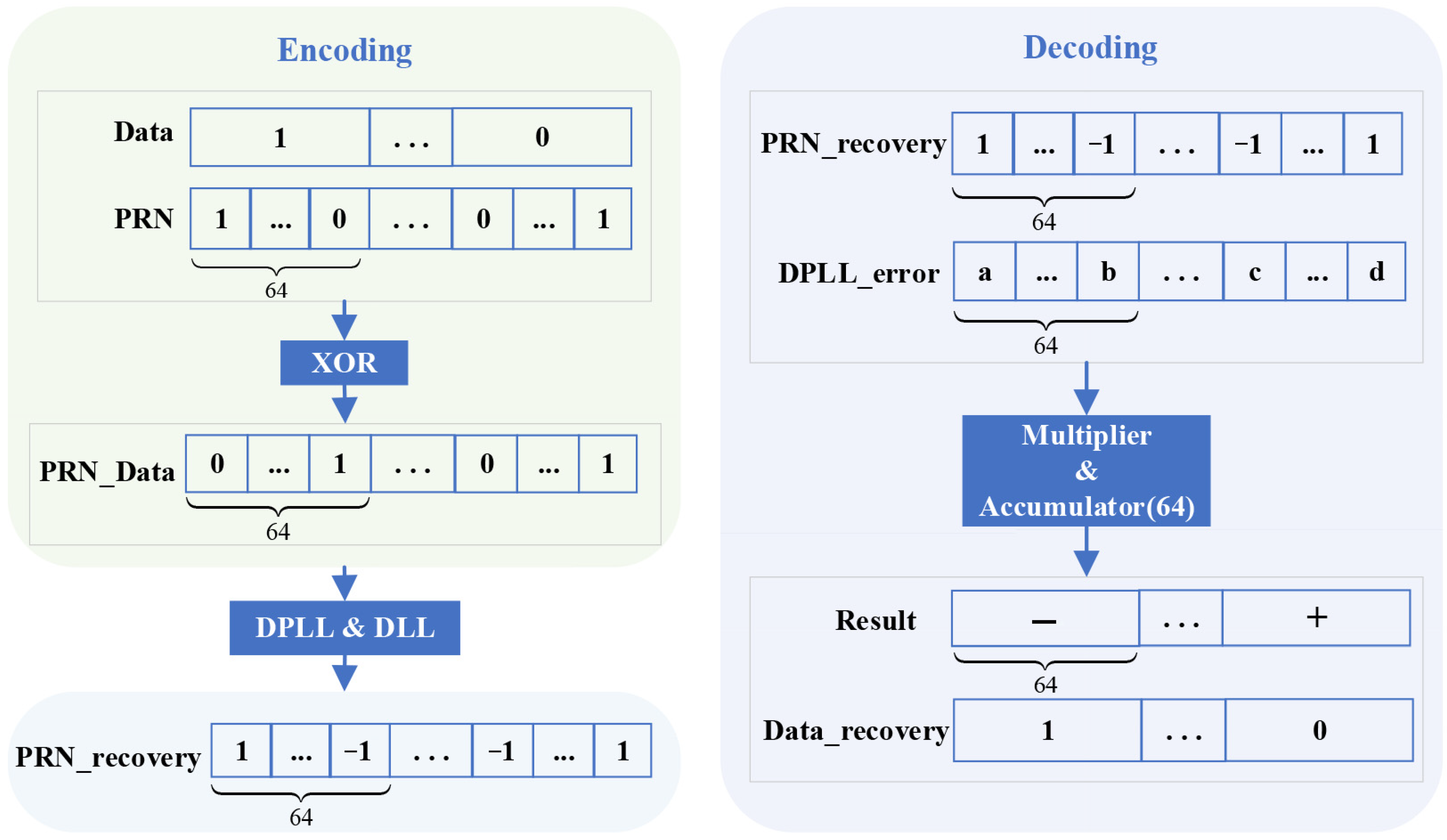
The encoding and decoding process of the PRN code and data code is illustrated in
Figure 3.
At the transmitter, the PRN code and the data code are combined via modulo-2 addition (XOR) to generate the composite signal, which is then modulated onto the laser carrier phase using an EOM. At the receiver, the PRN code delay is determined through the combined processing of a DPLL and a DLL. Based on this delay, the PRN code can be substantially recovered. The recovered signal and the error signal from the DPLL are integrated over one data period (corresponding to 64 chip lengths). The sign (positive or negative) of this integrated value determines the value of the recovered data code .
3. Experimental Verification of PRN Code Synchronization via Electronic Tests
The algorithms for the ranging and communication scheme were implemented on an FPGA development board for experimental validation. Based on the clock frequencies commonly used in DPLL, a system clock frequency of 80 MHz was selected, corresponding to a ranging resolution of 3.75 m (12.5 ns). Each PRN code chip corresponds to 32 clock cycles, resulting in a PRN chipping rate of 2.5 MHz. The update rate of the DLL loop corresponds to the full PRN sequence rate of 1.22 kHz. With a spreading factor of 64, the achievable data rate is approximately 39.06 kbps, meeting the requirement of about 15 kbps for communication data as specified in the LISA documentation [
26]. A modulation depth of π/16 rad [
11] was used, corresponding to the allocation of approximately 1% of the total received optical power.
The PRN code ranging algorithm was first verified at the electronic level, which also constitutes a critical step for ensuring synchronized communication data recovery. The electronic setup primarily consists of an analog-to-digital conversion module, an FPGA processor module, and a communication module. The core hardware was sourced primarily from Terasic (Hsinchu City, Taiwan, China), specifically the TR4-530 high-end development platform (Model: Stratix IV GX EP4SGX530KH40C2) [
27] and the Data Conversion High Speed Mezzanine Card (DCC) [
28], which features two ADC channels and two DAC channels. The signal under test is conditioned by the front-end analog circuitry of the ADC, then converted into a digital signal by the analog-to-digital mezzanine card. The digital signal processing, implementing the algorithms for the ranging receiver system, is executed within the FPGA. Finally, the processed information is transmitted via the communication module.
The flowchart for the electronic verification of the ranging scheme is shown in
Figure 4. The differential design, which splits the signal into two paths and subsequently differences them, maximizes the rejection of common-mode noise. A 6 MHz sinusoidal signal generated by a Direct Digital Synthesizer (DDS) implemented on the aforementioned FPGA platform simulates the heterodyne carrier signal. The PRN phase modulation is applied to this DDS-generated sinusoidal signal and output via the DAC on the FPGA mezzanine card. After passing through a low-pass filter, the signal is divided into two identical paths using a power splitter, connected to cables of lengths L1 and L2, respectively. These signals are then fed into the FPGA board via the two ADC channels of the DCC card for signal processing. After processing by separately instantiated DPLL and DLL structures of identical architecture, two tracking results,
and
, are obtained. The time difference of signal propagation in cables
and
is calculated by differencing these two results and multiplying by the clock period.
Figure 5 shows the physical setup of the electronic test bench. The cables used have a nominal length of 2 m each. Testing was performed by connecting varying numbers of these cables in series. It should be noted that the absolute lengths of the cables were not individually calibrated. Given potential variations inherent in cable lengths and connector interfaces, this experiment primarily evaluates the ranging accuracy.
The signal propagation velocity in the cables used is approximately 77% of the speed of light, equating to about 2.31 × 10⁸ m/s. One clock cycle corresponds to a distance of approximately 2.89 m. The following graph shows the results, representing the difference in tracking loop errors corresponding to various cable length differences.
Figure 6 shows that the tracking results fluctuate around a fixed value with a generally stable trend. Furthermore, this stabilized value aligns essentially with the actual length difference in the experimental setup. Conventional PRN code ranging studies typically derive accuracy by calculating the RMS of multiple discrete measurement results. In contrast, the ranging accuracy in this study is determined from the RMS of the error signal after the DLL loop has stabilized. This approach, utilizing a substantial data volume, yields a more reliable characterization of the error. The formula for calculating the RMS is given as:
where
represents the number of selected DLL error signal data points,
denotes the DLL error signal expressed in number of clock cycles, and
is the mean value of the DLL error signal samples.
Furthermore, since the DLL loop error signal operates at a rate of 1.22 kHz, it must be decimated before being processed by the on-board computer, typically to a range of 3–10 Hz [
18]. This decimation is implemented using a CIC decimation filter. The CIC filter is an optimized linear-phase FIR filter structure composed of comb filters and integrators [
29]. The transfer function of a single-rate CIC filter is given by the following equation:
where
is the transfer function of the integrator section, and
is the transfer function of the comb section. Here,
represents the number of cascade stages,
is the decimation factor, and
is the differential delay.
The CIC decimation filter employed in this work utilizes a cascade of three integrator stages and three comb filter stages. The schematic diagram of the structure is shown in
Figure 7 below. Specifically, with the number of stages N = 3 and the differential delay M = 1, the 1.22 kHz data is decimated by a factor of R = 122 to 10 Hz. When the decimation factor R = 407 is applied, the 1.22 kHz data is decimated by a factor of 407 to 3 Hz.
Approximately 780,000 samples of the code loop tracking error were collected. After CIC decimation filtering to 10 Hz, the data volume yielded 3161 points; when decimated to 3 Hz, the data volume became 944 points. The RMS values were subsequently calculated from these decimated datasets. The ranging results of the algorithm tested with cables of different lengths are presented in the
Table 1. The delays listed in the table are given in number of clock cycles.
For each incremental 4-m length difference, the corresponding differences in the tracked clock cycles are 1.4697, 1.4239, and 1.4446, respectively. Within acceptable error margins, the tracking loop can effectively measure the cable length differences. The ranging accuracy before CIC decimation ranges between 1–2 m. After decimation to 10 Hz, the accuracy improves to the range of 3–5 cm, and further decimation to 3 Hz yields an accuracy within 2–3 cm. The electronic tests successfully validated the PRN code synchronization, and the achieved ranging accuracy meets the specified requirements.
4. Optical Verification of the Integrated Ranging and Communication Scheme
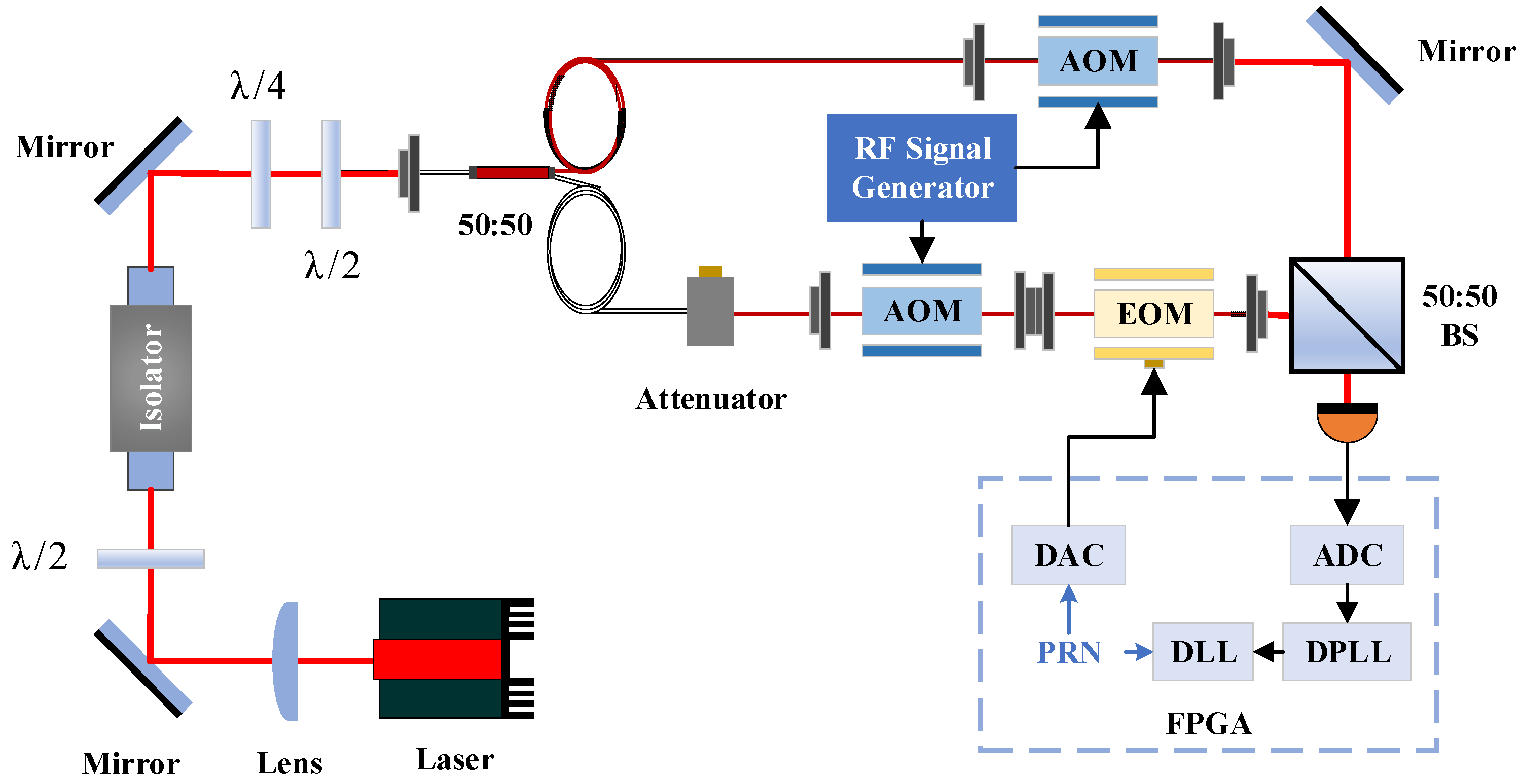
An optical experiment was conducted to validate the ranging system, with its schematic diagram shown below. The laser source selected was a 1064 nm NPRO (Non-Planar Ring Oscillator) laser with built-in power pre-stabilization capability. The laser beam was collimated and amplified through a lens assembly. The first λ/2 waveplate was rotated to maximize the power transmission through the optical isolator. The Faraday isolator only transmits light with a specific polarization state while maintaining beam position consistency between its input and output ports. The output laser was split into two beams, designated as the master laser and the follower laser, using a 50:50 polarization-maintaining fiber beam splitter. An acoustic-optic modulator (AOM, manufactured by CETC, Chongqing, China using polarization-maintaining fiber) was employed to establish a 6 MHz frequency offset between the two beams to facilitate heterodyne interference at the receiver. The data-encoded PRN code was phase-modulated onto the follower laser via an electro-optic modulator (EOM, provided by CETC, Chongqing, China). Since clock offset was not considered in this experiment, the data-encoded PRN code, along with the DPLL and DLL algorithms at the receiver, were all implemented and synchronized within the same onboard FPGA. The experimental setup for optically verifying the unidirectional integrated ranging and communication scheme is schematically illustrated in
Figure 8.
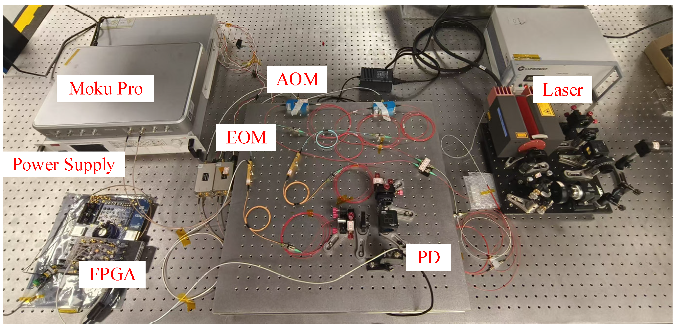
Figure 9 shows a photograph of the optical experimental setup. An InGaAs photodetector was employed, where the optical intensity incident on the photosensitive area of the photodiode generates a photoelectric effect, thereby converting optical power to electrical current. The conversion coefficient between optical power and current, namely the photodiode responsivity *R*, is 0.3 A/W. The local oscillator laser power was set to 2 mW, resulting in 1 mW after the beam splitter (BS). The other beam, serving as the received signal laser, was attenuated to 10 μW using a fiber attenuator, yielding 5 μW after the BS. The heterodyne interference efficiency between the two laser beams was approximately 0.7.
The EOM is driven by the data-encoded PRN signal. The half-wave voltage of the EOM used is 1.8 V. The maximum output voltage from the FPGA’s DAC is 400 mV. The relationship between the modulation depth employed in the experiment and the EOM driving voltage is given by the following equation:
The modulation depths employed in the experiment and their corresponding driving voltage values are listed in the
Table 2.
Under constant experimental bench conditions, the acquisition and tracking capabilities of the receiving system for the PRN code were validated by altering the code phase offset modulated onto the EOM, i.e., the fundamental delay in clock cycles. The modulation depth was uniformly set to π/9, and tests were conducted without communication data. The experimental results are presented in
Table 3. Since the EOM output is coupled into an optical fiber before interference occurs via a free-space optical path, a unified speed of light cannot be applied for distance conversion. Consequently, the delay values are expressed in units of clock cycles.
The discrepancy between the experimental results and the theoretical delay remains nearly constant, indicating a stable optical path length from the EOM output to the photodetector. The experimental data presented in the table validate the system’s feasibility.
Table 4 summarizes the experimental results under different modulation depths, with the incorporation of 39 kbps communication data encoding and a fixed baseline delay of 1024 clock cycles.
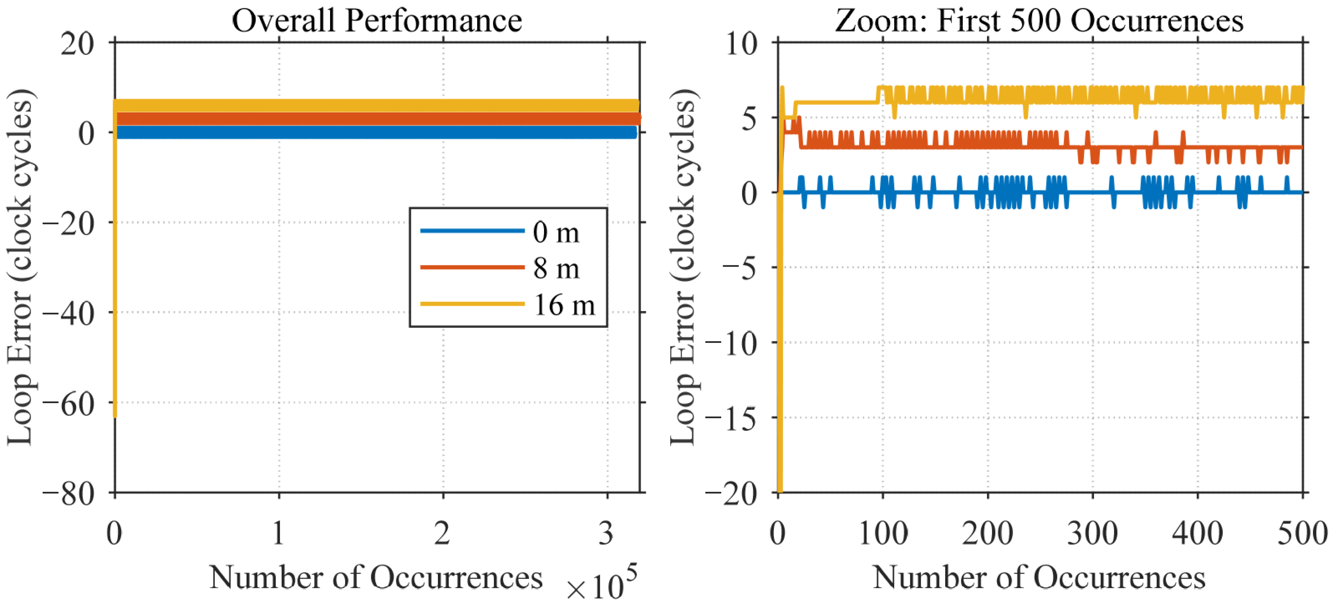
The acquisition and tracking functions remain operational after the introduction of data encoding, albeit with minor deviations. Under a modulation depth of π/9, a comparison of the PRN code tracking loop error with and without data encoding is presented in
Figure 10. The results indicate that data encoding exerts a certain level of influence on the PRN tracking performance; however, the resulting error remains within acceptable limits.
The ranging accuracy was determined by calculating the Root Mean Square (RMS) value of the stabilized loop tracking error. The loop error signal was sampled at 1.22 kHz before CIC decimation. A total of 668,200 error samples were collected. After decimation to 10 Hz, approximately 5477 samples remained, while decimation to 3 Hz yielded about 1641 samples. The resulting ranging accuracy, expressed in clock cycles, is presented in
Table 5.
Data encoding introduces a minor, albeit negligible, degradation in the post-CIC decimation ranging accuracy, demonstrating the integrated nature of the ranging and communication system. Furthermore, the ranging accuracy deteriorates with decreasing modulation depth. Given a clock cycle period of 12.5 ns and assuming the speed of light in vacuum
, the ranging accuracy after decimation to 3 Hz under a modulation depth of π/32 with 39 kbps data encoding, corresponding to
clock cycles, is calculated as follows:
Therefore, under a received optical power of 10 μW, a modulation depth of π/32 results in an allocated optical power of approximately 100 nW for inter-satellite ranging. While simultaneously maintaining 39 kbps communication data transmission, the ranging accuracy achieved through laboratory optical experiments significantly surpassed the 1 m absolute ranging requirement.
5. Conclusions
This paper presents a low-power scheme for absolute inter-satellite distance measurement with integrated communication functionality, developed within the context of space-based gravitational wave detection and implemented via FPGA-based software (Intel Quartus Prime, version 18.1). This integrated ranging and communication scheme was validated through electronic-level experiments employing a Direct Digital Synthesizer (DDS), along with preliminary optical verification. Experimental results demonstrate that under laboratory conditions with a received optical power of 10 μW, utilizing a modulation depth of π/32 rad (consuming approximately 1% of the optical power) while simultaneously supporting a communication data rate of 39 kbps, a ranging accuracy of 0.0064 m (at 3 Hz) is achievable, significantly surpassing the 1 m accuracy requirement. The functional correctness of the system architecture, algorithmic workflow, and hardware integration was validated through optical experiments conducted under high signal-to-noise ratio conditions.
This work aims to validate the functional effectiveness and algorithmic correctness of the integrated ranging and communication scheme. The experimental verification was conducted under controlled laboratory conditions with a high signal-to-noise ratio, which effectively isolated and resolved fundamental issues in system integration and algorithm implementation, thereby clearing obstacles for subsequent performance optimization under more stringent conditions. We recognize that a series of critical challenges must be addressed to bridge the gap between this study and practical engineering applications. These include operation under realistic received optical power at the nW level and mitigating the effects of clock offset and jitter noise when independent clocks are employed. These aspects constitute direct and crucial next steps in our technology maturation plan. Furthermore, ensuring that the impact of these auxiliary functions on the scientific interferometric measurements remains below the stringent requirement of continues to be a core driver of our ongoing performance optimization efforts. Although the core concept of integration was pioneered by the LISA team, our work consolidates its practical feasibility through a detailed implementation and ground-based demonstration, providing concrete technical references for subsequent engineering development. Therefore, this work not only successfully validates the technical feasibility of a low-power integrated scheme but also provides a reliable, ground-verified technical baseline for an auxiliary subsystem, which is essential for constructing future gravitational wave observatories aimed at exploring the unknown universe.
