Abstract
This work presents the application of a hybrid adaptive Kalman filter (HAKF) for the implementation of a shunt active power filter (SAPF), enabling selective harmonic and interharmonic compensation in real time. The hybrid term refers to the combination of a DFT-based harmonic grouping method with the adaptive Kalman estimation framework, which preserves the classical estimation method of the Kalman filter while dynamically defining its state-space model according to the spectral composition of the load current. This allows the accurate identification and parametrization of the HAKF state matrices and ensures precise individual quantification of each frequency component. In this way, the SAPF control system can select individual components to be eliminated, either totally or partially. Selective compensation is particularly useful when the compensating current required for full mitigation of the nonfundamental frequency components exceeds the SAPF current capability. Partial compensation can also be employed to match the compensating current with the maximum allowable SAPF current. Based on this, a simple selective compensation strategy is proposed to demonstrate the effective behavior of the SAPF under such conditions. A single-phase power system consisting of the proposed SAPF and a nonlinear load has been simulated using Matlab/Simulink. The simulation results confirm the effectiveness of the proposed system in mitigating harmonics and interharmonics, thereby enhancing power quality, while validating both the current processing method and the use of the HAKF in the implementation of the selective SAPF.
1. Introduction
The widespread adoption of power generation systems and nonlinear loads based on power electronics has significantly contributed to a deterioration of power quality in distribution networks [1,2,3,4]. As a result, mitigating harmonic distortion has emerged as a central research objective in the effort to enhance power quality, fostering increasing interest within the international scientific community in the accurate measurement and effective mitigation of these inefficiencies [5,6]. Different standard development organizations have issued technical guidelines to quantify and limit waveform distortions propagated through the electrical grid. For instance, IEC 61000-4-7 [7] defines a methodological framework for measuring harmonics and interharmonics in power systems and specifies the requirements for compliant measurement instrumentation. Likewise, IEEE Std 519-2014 [8] provides system-level recommendations for establishing acceptable limits of voltage and current distortion, while IEEE Std 1459-2010 [9] outlines power measurement standards applicable to sinusoidal and non-sinusoidal, balanced and unbalanced operating conditions. According to [10], in single-phase systems, power quality inefficiencies primarily arise from energy losses associated with reactive power, as well as from harmonic, interharmonic, and subharmonic components.
Two principal approaches may be considered for reducing the impact of harmonics on power quality: either by preventing their generation—through PWM modulation techniques aimed at selective harmonic elimination, thereby reducing the total harmonic distortion (THD) of the voltages and currents generated in power converters [11]—or by mitigating them using active power filters (APFs). APFs have proven to be effective tools for improving electrical power quality [10,11,12,13]. Among these, shunt APFs (SAPFs) operate as controlled current sources [14] connected in parallel with inefficient loads at the point of common coupling (PCC), as illustrated in Figure 1. SAPFs enhance power quality by compensating for inefficiencies generated by electrical loads, thereby preventing their propagation through the power grid. Additionally, APFs have been incorporated into power generation systems, particularly in renewable energy applications, where they contribute to both energy injection and the correction of inefficiencies [15,16,17].
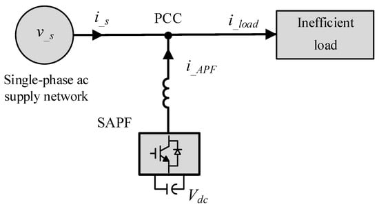
Figure 1.
Diagram of an SAPF installation.
Ideally, active filters could achieve complete compensation for inefficiencies measured downstream of the PCC, including reactive power, distortion power, and unbalance power (in three-phase systems). In this global compensation approach, the SAPF generates all load current components except for the fundamental active current [6,18,19], since it conveys the useful power supplied by the electrical network. However, full compensation is constrained by the power capacity of the SAPF semiconductors, as this may exceed their operational limits. Under such conditions, it becomes necessary to independently identify the non-efficient current components before applying selective or partial compensation. Once these components are identified, a compensation strategy must be defined to determine which components will be addressed and to what extent. This approach enables multiple compensation schemes [19,20], aiming to generate a reference signal for SAPF current control that ensures compliance with the semiconductors’ current limits while achieving the best possible compensation.
Currently, multiple approaches are used for the identification of non-fundamental components in voltages and currents. However, interharmonic identification presents a particular challenge due to their frequencies not being integer multiples of the fundamental component. In [21], the authors present a classification of different interharmonic identification methods, while [22] summarizes these techniques into four major categories, as illustrated in Figure 2.
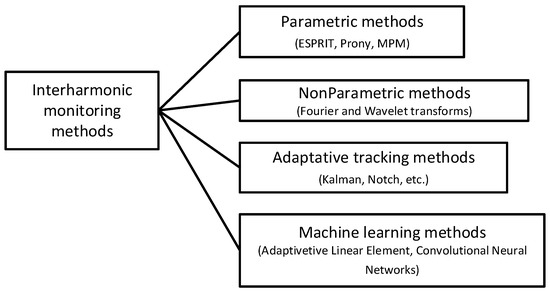
Figure 2.
Classification of interharmonic measurement methods.
Parametric methods enable the direct estimation of various signal parameters, such as the frequency, amplitude, and phase of individual harmonic components. These techniques rely on modeling the signal as a linear combination of multiple exponential or sinusoidal components, with the corresponding parameters extracted through algebraic or optimization-based approaches. Representative parametric methods include:
- -
- ESPRIT (Estimation of Signal Parameters via Rotational Invariance Techniques) estimates harmonic and interharmonic frequencies by modeling the signal as a sum of complex sinusoids. It exploits rotationally invariant subspaces derived from singular value decomposition to achieve high-resolution frequency estimation, even under short or noisy signal conditions [23].
- -
- Prony’s method models the signal as a sum of complex exponentials and fits these models to the data using a linear system. This approach enables precise estimation of harmonic and interharmonic frequencies, amplitudes, and phases, particularly in short time windows [24].
- -
- The Matrix Pencil Method (MPM) also represents the signal as a sum of complex exponentials. It constructs shifted data matrices to form a matrix pencil, whose decomposition provides high-resolution estimates of the signal’s spectral components [25].
Non-parametric methods differ from parametric approaches in that they do not rely on a predefined signal model to estimate parameters. Instead, they perform a transformation or decomposition in the time–frequency domain, identifying the frequency and amplitude of harmonic and interharmonic components based on energy distribution characteristics. Some of the most widely used non-parametric techniques are based on:
- -
- Fourier Transform. The Discrete Fourier Transform (DFT) [3,26] is one of the most widely used classical methods for identifying the harmonic components of a signal. However, when the signal contains components that are not integer multiples of the DFT’s fundamental frequency, the results are affected by spectral leakage and picket-fence effects [27,28]. These phenomena hinder the direct identification of the signal’s frequency components.
- -
- Wavelet Transform. The Discrete Wavelet Transform (DWT) enables the decomposition of a signal into multiple frequency bands with variable resolution, facilitating the extraction of harmonic components even in the presence of nonlinear or transient disturbances [29,30,31]. However, due to its variable resolution, detection is highly dependent on the choice of the analysis window. If the window is too small, low-frequency information related to interharmonics may be lost. Conversely, if the window is too large, the ability to detect high-frequency details is compromised. Moreover, the computational complexity and the need for additional techniques to accurately identify interharmonics and subharmonics pose additional challenges to the practical application of this method.
Adaptive tracking methods perform real-time identification and tracking of signal characteristics through a closed-loop update mechanism. By adjusting model parameters or filter structures in real time, these methods can overcome limitations affecting spectral resolution. Among the most used adaptive tracking techniques are:
- -
- The Linear Kalman Filter (LKF) is based on the estimation of state variables, followed by the minimization of the error between the system output and the estimated values. It is a recursive algorithm, which is described in more detail in the following section [32].
- -
- The Adaptive Notch Filter (ANF) is a technique used to eliminate specific frequency components, typically harmonics or interference, from a signal by adjusting its parameters in real time to track changes in the frequency or amplitude of the disturbance [29].
Machine learning is a data processing approach through which signal characteristics can be identified and interharmonic parameters can be independently extracted. Among the most influential methods are:
- -
- Adaptive linear element (ADALINE) is a linear neural network model that estimates a weighted linear output from input signals, with the weights updated using supervised learning algorithms. Recent advancements include hybrid ADALINE-FXLMS algorithms for fast and accurate estimation of harmonic and interharmonic components in noisy environments [33], as well as master–slave ADALINE architectures for real-time power system analysis [34].
- -
- Convolutional Neural Networks (CNNs) are deep neural network architectures designed to process grid-like data structures, such as images or time-series signals. Their core feature is the use of convolutional operations to automatically extract relevant features from input data. Harmonic CNNs, which integrate spectral information via circular harmonic filters, have demonstrated improved performance in tasks requiring translation and rotation equivariance [35], and have been successfully applied to spectral feature extraction in signal classification [36].
In this field, the authors have recently proposed a measurement method based on the grouping of DFT results to precisely determine the number of signal components, combined with a Kalman filter to accurately estimate the amplitude and frequency of fundamental and non-fundamental components [37]. In this work, this approach is referred to as HAKF, since it combines a DFT-based harmonic grouping stage with the classical Kalman filter estimation method. This hybrid structure allows the filter’s state-space model to be dynamically defined according to the spectral composition of the load current, enabling accurate estimation once a new stationary interval is detected. The proposed groupings improve upon those defined in IEC 61000-4-7 and enable a more precise determination of the number of component frequencies in a signal. Once this number is established, the Kalman filter provides accurate estimates of the component frequencies (harmonics or interharmonics). Compared to the approaches discussed above, this method offers several advantages: it does not require strong assumptions about the signal model (parametric methods); it is not limited by fixed resolution issues (non-parametric methods); it does not depend on predefined tuning parameters (adaptive filters); and it does not require extensive training datasets (machine learning). Therefore, the method provides a balanced alternative that combines accuracy, adaptability, and computational efficiency.
From the perspective of their application in SAPFs, parametric methods such as Prony, ESPRIT, or the Matrix Pencil Method provide high-resolution estimates of harmonic and interharmonic components, even with short observation windows. However, their reliance on predefined mathematical models, together with their significant computational cost, limits their practical application in real-time SAPF control. Conversely, non-parametric approaches, such as DFT, STFT, or wavelet-based techniques, are simpler and standardized (e.g., IEC 61000-4-7) but suffer from resolution constraints, window-dependent accuracy, and latency, which hinder their suitability for fast and precise reference current generation. Adaptive tracking techniques, such as Kalman filters or adaptive notch filters, offer real-time tracking capabilities and dynamic adaptability, yet their performance is strongly dependent on accurate tuning of filter parameters and noise models, which can compromise robustness under rapidly changing load conditions. Machine learning techniques, including ADALINE and convolutional neural networks, demonstrate strong potential for harmonic characterization in noisy environments, but their dependence on large training datasets and their high computational complexity make them unsuitable for embedded real-time SAPF control.
In contrast, the authors’ HAKF method—based on the grouping and filtering of DFT results combined with a Kalman filter—achieves a balance between accuracy, adaptability, and computational efficiency. These features make the proposed approach highly suitable for real-time reference current determination in SAPF applications. Table 1 presents a comparison between the different methods, including their computational cost and feasibility for SAPF implementation.

Table 1.
Comparison of Harmonic Identification Methods for SAPF Reference Current Generation.
Building on this method, the present work introduces a novel SAPF capable of performing global, selective, and partial compensation of the harmonic, interharmonic, and subharmonic components of inefficient load currents. The main contribution of this work is the integration of the harmonic, subharmonic, and interharmonic identification method previously introduced by the authors in [37] into an SAPF. This integration enables a more accurate calculation of the reference signal for SAPF current control compared to existing approaches, allowing the SAPF output to dynamically adapt both to variations in the harmonic components present in the load current and to the available energy at any given time.
The article is organized as follows: Section 2 provides a description of the method used to extract the current components. Section 3 explains how the reference currents are obtained for global, selective, and partial compensation. Section 4 describes the simulation setup, including the nonlinear load and the scenarios analyzed. Section 5 discusses practical considerations for real-time implementation, addressing computational aspects and feasibility in hardware platforms. Finally, Section 6 summarizes the main conclusions of the work.
2. Determination of the Frequency Components of the Load Current
Selective elimination of harmonic and interharmonic components by an SAPF requires accurate real-time measurement and identification of the components to be suppressed. In this work, this task is carried out using the HAKF method presented in [37]. As indicated before, this approach combines a DFT-based grouping stage with the classical Kalman estimation framework, allowing the state-space model to be dynamically configured according to the harmonic composition of the load current. The Kalman filter then provides accurate real-time estimation of the amplitude and frequency of each identified component, enabling selective and adaptive compensation. A brief description of the fundamental aspects of the method is presented below.
The LKF is a recursive algorithm that estimates the value of the state variables () of a system. It assumes a stochastic model for the estimation of the state variables. This model must be defined before starting the recursive estimation process. The standard discrete LKF formulation is employed here without structural modifications. The goal is not to develop a new Kalman algorithm but to exploit the Kalman framework as an optimal recursive estimator for harmonic and interharmonic components.
The system model is expressed as:
where is the state vector, the state transition matrix, process noise (intrinsic error), the system output, the output matrix, and the measurement noise. The subscripts k and k + 1 denote variables at the current and next sampling instants, respectively.
are uncorrelated white noises. Their known covariances are:
where
represents the mathematical expectation.
is the covariance of the intrinsic system noise.
is the covariance of the noise measured in the output.
It is assumed that matrices and are known.
The LKF operates by minimizing the error between the estimated state variables, denoted as , and their actual values . The state error in the estimation stage is defined as:
where is the actual state value at time k, and is the estimation of the stage at time instant k, which is obtained by model prediction from previous information at instant k − 1. The superscript (−) indicates that the calculation for this time instant (k) was performed using the values obtained or estimated at the previous instant (k − 1), and the caret symbol (^) indicates that the displayed value is an estimation rather than a real value.
Equations (1)–(13) constitute the recursive LKF model. Equation (7) shows the correction phase, where the value of the state is estimated based on the prediction state estimation and the measured (), which lead to the error between the output measured value and its estimated value (). The Kalman filter gain () is the weighting factor of the error:
The optimal error weighting factor (), also known as the Kalman gain matrix, is calculated using Equation (8).
where is the covariance of the prediction stage estimation error defined as:
The update of the error covariance matrix (), that is the variance of the correction stage, is calculated as in (10).
where I is the identity matrix.
The value of the state at the future instant, using the current values (), is obtained in Equation (11) as follows:
Finally, the estimation of the error value that will be obtained () is calculated in (12). This value is used to estimate the covariance of the future error () in (13).
Once the equations and matrices are defined, the recursive algorithm of the LKF can be initiated. Figure 3 shows the flow chart of the recursive algorithm.
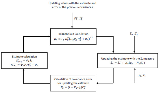
Figure 3.
Flow diagram of the recursive Kalman filter calculations.
is the system state matrix, and it must match the system model. In the context of harmonic identification in the load current, properly sizing this matrix requires knowing the number of harmonic components. The accuracy of the estimation then depends on the LKF model [38]. The LKF will converge if the model includes a number of states equal to the harmonic components of the signal to be estimated.
The LKF will attempt to adjust the output value of the developed model to the real value of the signal, aiming for each component’s output to approximate the real value as closely as possible by minimizing the error between the real value and the estimated one (12). This approach may result in the overall output value of the LKF being exactly equal to the desired signal, but the individual components obtained (7) may differ from the real components [38].
There are variations of the Linear Kalman Filter (LKF) that allow certain elements of the filter Equations (1)–(13) to adapt, enabling the state variable estimates to track changes in the input signal. In [32], the author modifies the estimation of the measurement noise variance , Equation (4), using a correlation-based function that reduces bias in the state variable estimates when the system is in steady-state. In [39], the authors present an adaptive Kalman filter method in which the system noise variance , Equation (3), is variable and can be adjusted at each iteration. These adaptive methods are valid as long as the number of state variables in the Kalman matrix () remains constant.
In most applications where the LKF is used for harmonic component estimation, the state matrix () is modeled such that the state variables correspond to the harmonic components to be estimated. Therefore, adaptive methods based on the adjustment of the variance matrices and are valid when variations occur around the operating point, but not when the number of harmonic components changes. In such cases, these methods fail to adjust the number of states in the () matrix to reflect the actual signal variation.
This mismatch between the number of state variables in the model and the actual number of harmonic components in the signal may yield an accurate global estimation output (Equation (2)) but inaccurate individual estimates of each state variable [37,38].
To overcome this limitation, the HAKF method proposed by the authors introduces adaptability by dynamically resizing the state matrix according to the harmonic composition identified through the DFT-based grouping, rather than modifying the noise covariance matrices or . This reconfiguration mechanism ensures that the Kalman model always remains consistent with the real spectral content of the load current.
The flowchart in Figure 4 provides a concise overview of the steps followed in the process developed to obtain the harmonic components of the load current. This procedure corresponds to the measurement method proposed by the authors and is described in greater detail in [37].
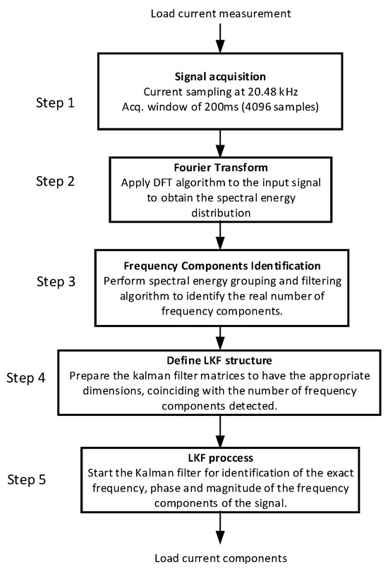
Figure 4.
Flowchart of the identification algorithm steps.
Step 1 involves data acquisition in accordance with the specifications defined in IEC Standard 61000-4-7 [7]. This standard establishes a 200 ms acquisition window for signals with a fundamental harmonic of 50 Hz, and a DFT resolution of 5 Hz. A switching frequency of 20.480 Hz is selected, resulting in a dataset of 4096 samples (a power-of-two value, as recommended by the standard).
Step 2 consists of computing the DFT (Discrete Fourier Transform) of the stored samples, which yields the magnitude and frequency of each harmonic component present in the load current. However, in the presence of interharmonics, due to the effects of picket fence and spectral leakage, the DFT results may not accurately represent the actual harmonic components. Consequently, these results cannot be directly used to generate a reference signal for a SAPF (Shunt Active Power Filter).
Step 3 focuses on identifying the actual components using the method described in [37], which builds upon the harmonic grouping concept presented in [7], with specific innovations introduced in the grouping and filtering processes to enhance the detection of current signal components. This step enables accurate identification of the number of frequency components in the load current. However, their frequency, magnitude, and phase characteristics are only approximate.
Step 4 uses the actual number of harmonic components to correctly dimension the Kalman filter matrix, ensuring precise quantification of these characteristics after the filter is executed.
Step 5 executes the LKF (Linear Kalman Filter). Once the filter reaches convergence across all internal states, the current components are accurately obtained and made available for use as reference currents for the SAPF.
After this process, LKF output is continuously monitored to detect any loss of convergence. If this occurs, a new identification cycle is triggered. This adaptive mechanism dynamically resizes the state matrix Φk and updates the estimation parameters, allowing the filter to maintain accuracy and stability under non-stationary operating conditions.
3. SAPF Reference Current Generation
As previously discussed, the SAPF operates as a controlled current source that injects current into the PCC. Figure 5 illustrates a detailed block diagram of a SAPF compensation system. This system comprises four main functional blocks: synchronization, load current components estimation, reference current generation, and current control. The synchronization block extracts the phase angle of the supply voltage, required both for current reference generation and DC-link voltage regulation. The non-fundamental components identification stage uses the proposed HAKF method to determine the harmonic and interharmonic components present in the load current. Once the non-fundamental components of the load current—denoted as (ih1, ih2, …)—are accurately identified, the reference current (iref) can be generated. This reference is used by the SAPF current controller to ensure the injection of the appropriate compensating current (iF) into the PCC. The current control block ensures that the injected SAPF current tracks this reference, while the DC-link voltage controller maintains the converter’s internal energy balance. As a result, these non-fundamental components are prevented from being supplied by the supply network, leading to a reduction in the THD of the supply current (THDi) and an overall improvement in power quality.
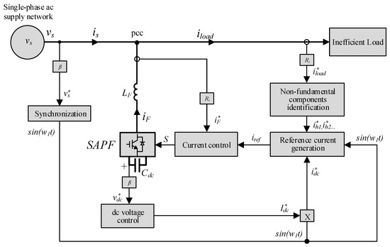
Figure 5.
Block diagram of the SAPF compensation system showing the main control stages.
The load current can be expressed as in (14), comprising both fundamental and non-fundamental components. The SAPF current, defined in (15), enables full compensation of the non-fundamental components upstream of the PCC, while maintaining the dc-link voltage (Vdc) at its desired level through the current (idc), obtained using a dc voltage controller. This configuration allows for an enhancement of power quality indices such as THDi and power factor (PF).
It is important to note that compensating for the fundamental reactive power, which would further improve the PF, is not the objective of this work. Nevertheless, if required, the fundamental reactive current can be easily determined, as the phases of both the fundamental values of grid voltage and load current are known.
However, performing global compensation does not require the individual identification of the current components since the non-fundamental components can be obtained indirectly by subtracting the fundamental component from the load current (16). The only requirement is the identification of the fundamental component.
In this work, the individual identification method described in Section 2 is employed for selective partial compensation of the non-fundamental components of the load current, particularly in scenarios where the SAPF power capacity is insufficient for global compensation. Accordingly, Equation (17) introduces a set of weighting constants () that enable individual scaling of each compensation component.
The weighting constants allow enabling or disabling (0/1) compensation for each non-fundamental current component, or applying partial compensation by selecting a value between 0 and 1. The compensation strategy and, consequently, the reference current formation rely on identifying the most harmful components to prioritize their compensation while ensuring that the maximum current of the power converter () is not exceeded, as expressed in Equation (18).
This equation allows for all possible compensation combinations, enabling the selection of the most suitable compensation strategy at any given moment. However, it is important to consider that working with non-fundamental components individually does not provide an intuitive understanding of the best way to fully utilize the available power of the SAPF. When dealing with individual instantaneous sinusoidal components, their sum results in compensation currents whose maximum value is not necessarily the sum of the maximum values of the individual components. Instead, it may be greater or smaller depending on the frequency and phase of the components. From a power quality perspective, it may be more advantageous to find the combination of components that maximizes the utilization of the inverter’s power without instantaneously exceeding its maximum current. To solve the optimization problem presented in Equation (18), a powerful algorithm must be developed. However, a simplified approach will be used in this work with initial attempts to apply global compensation (). If is exceeded, the least harmful component is removed from the reference current. This process is repeated iteratively and eliminates the next least harmful component one by one until the reference current remains within the inverter’s maximum allowable limit. The last component eliminated from the reference current will be scaled to adjust the maximum value and not exceed the established limit.
To illustrate the formation of the reference current in a simple way, let us consider the load current of Equation (19), composed of a fundamental component and four non-fundamental components, ih1 to ih4, ordered by their increasing level of harmfulness. Assume that is the maximum instantaneous value of the compensating current of Equation (20), which consists of the four non-fundamental components plus the fundamental component required to compensate for power losses that reduce the dc capacitor voltage, idc.
Figure 6 shows a case in which exceeds . In this situation, the least harmful component, , cannot be compensated at all, and the third most harmful component, , must be partially compensated to meet this current limitation. The final compensating and reference currents are presented in Equations (21) and (22).
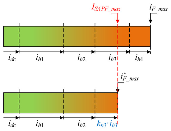
Figure 6.
Representation of the selective compensation strategy showing the limitation imposed by the maximum SAPF current () and the resulting partial compensation of the less harmful components.
The flowchart explaining the reference current formation is presented in Figure 7. Once the load current components have been accurately obtained after executing the Kalman filter process, the reference current formation algorithm is initiated. Finally, a reference current that maximizes the utilization of the power converter’s capabilities is obtained. In the next section, the proposed SAPF will be simulated to evaluate its performance and validate the effectiveness of the compensation strategy.
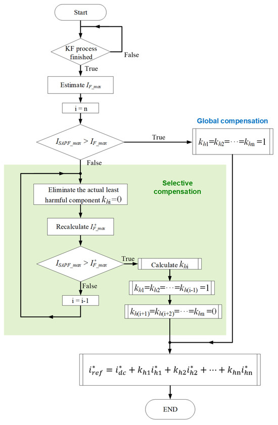
Figure 7.
Flowchart of the reference current generation process, illustrating the transition from global to selective compensation according to the maximum allowable SAPF current.
It must be noted that, due to the nature of components like interharmonics—whose frequencies are not exact multiples of the fundamental component—precisely determining the maximum value of is not trivial. There is no exact repetition period for the current signal, and if one exists, it would be extremely long.
The theoretical maximum value of occurs when all its components are phase-aligned (reaching their peak at the same time). In this case, the maximum value would be the sum of the individual amplitudes. Although this is unlikely in practice (as the signals have different frequencies and phases) this value is used in this work to simplify the computation process.
4. Simulation Results
A simulation setup matching the system shown in Figure 5 has been developed in Matlab-Simulink to verify the operation of the proposed SAPF for the total or partial compensation of non-fundamental components while including subharmonics and interharmonics in the load current. The sequential processes applied to load current to obtain the reference current, matching with the steps followed in Figure 4 and Figure 7, are implemented in Matlab user-functions in Matlab code. To facilitate the simulations, the dc voltage has been fixed using a 500 V dc voltage source, eliminating the need for a voltage controller. The filter inductance value is LF = 3 mH. A one-cycle current controller working at 20 kHz [40] is used to perform current tracking and generate the gate signals for the power converter. The grid voltage is a sinusoidal fundamental component of 50.1 Hz and rms 230 V.
A non-efficient load has been synthesized to include the consumption of subharmonic and interharmonic currents. The load current components are listed in Table 2, while its waveform is shown in Figure 8. This current consists of five components. In ascending order of frequency: component 1 is a subharmonic at 22 Hz; component 2 is the fundamental component at 50.1 Hz, matching the AC voltage frequency; and components 3, 4, and 5 are interharmonics at 71.9 Hz, 122 Hz, and 149.7 Hz, respectively. The load current presents a total harmonic distortion of THDi = 20.38%.

Table 2.
Load current components.
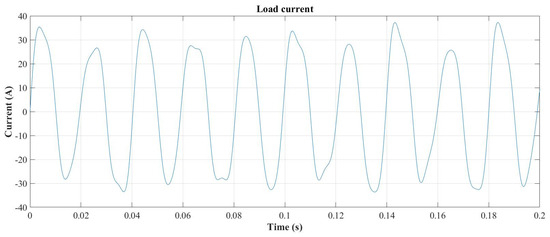
Figure 8.
Load current waveform.
Three simulations are presented. In the first one, the SAPF maximum current is set to 15 A, enabling the global compensation of all non-fundamental components. In the second simulation, the SAPF maximum current is limited to 10 A, requiring the algorithm to apply selective compensation. In this case, the 22 Hz component (identified as the least harmful) is only partially compensated to stay within the current limit. Finally, the last case simulates a change in the load current that experiences an increase in the number of non-fundamental components while the SAPF is operating.
4.1. Case I. Global Compensation
In this case, has been set to 15 A. The simulation follows this timeline:
- At t = 100 ms. Start data acquisition.
- At t = 300 ms. Data acquisition finished. Perform DFT, grouping and filtering processes, and sizing of Kalman matrices. Start Kalman filter process.
- At t = 500 ms, the Kalman filter achieves convergence. Perform the reference forming algorithm and start the SAPF compensation.
Before the SAPF can start compensating, the processes described earlier (Figure 3) must be completed to obtain the reference current. After 200 ms of data acquisition, the first DFT is performed over the load current samples according to the parameters specified in the standard [7]. The spectral components obtained are shown in Figure 9, where the effects of picket fence and leakage phenomena can be observed.
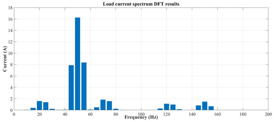
Figure 9.
Load current DFT results.
The DFT results are post-processed using the grouping and filtering method to estimate the real spectral components of the load current [37], resulting in the identification shown in Table 3. Although similar to the real values of magnitude and frequency, these results cannot be used to create the reference current for the SAPF. However, the obtained data reveals that the load current contains five components, and this enables a proper sizing of the Kalman filter matrices and the initialization of its internal states—as well as ensuring an accurate identification of current components. Once these steps are completed, the Kalman filter algorithm is executed starting at 300 ms.

Table 3.
Estimated load current components after grouping and filtering.
The Kalman filter performs a real-time estimation of the current components and achieves convergence in all its internal states after 200 ms. Figure 10 illustrates the time evolution of the Kalman filter estimation process for the fundamental component. Similarly to what is shown in Figure 10, the Kalman filter accurately estimates the other current components. However, these are not presented here to avoid redundancy.
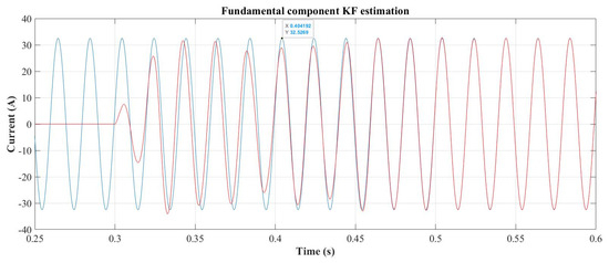
Figure 10.
Load (blue) vs. Kalman filter estimation (red) for the fundamental component.
Once the Kalman filter process concludes at 500 ms, the load current components are precisely identified and quantified, matching the magnitudes and frequencies shown in Table 2. Since the non-fundamental components are individually available at this point, the reference current formation algorithm is executed.
For this example, has been set to 15 A, and IF_max (computed as the sum of the individual amplitudes of the non-fundamental components) is 13.03 A. Therefore, the algorithm presented in Figure 6 determines global compensation for all non-fundamental components and results for the reference current are shown below:
where
After the reference currents have been determined at 500 ms, the current control is enabled and the SAPF begins to compensate the currents upstream from the PCC. The SAPF compensating currents are shown in Figure 11, while the compensation result is shown in Figure 12, where the ac grid current (red waveform) becomes a fundamental sinusoidal current of 32.5 A at 50.1 Hz with a superimposed switching ripple of 2 A at 20 kHz and showing a THDi = 3.07%. Figure 13 shows the components of the grid current when the SAPF is operating.
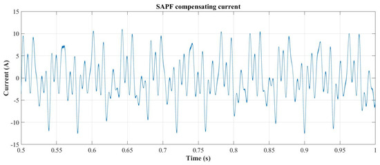
Figure 11.
SAPF compensating current for global compensation.
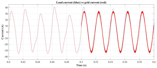
Figure 12.
Load vs. ac grid current with SAPF starting at 500 ms.
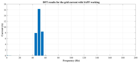
Figure 13.
DFT spectrum of the grid current during SAPF operation.
4.2. Case II. Selective Compensation of Non-Fundamental Components
The load current is the same as Case I; however, in this case, has been reduced to 10 A to force selective compensation mode. The simulation follows the same timeline as Case I, with the differences arising from the reference current formation algorithm. In this case, < IF_max (13.03 A) and the algorithm presented in Figure 7 determine the selective mode and initiate the recursive component elimination, starting with component 1 of 22 Hz as the least harmful one. By eliminating this component, the new maximum compensating current is reduced to 9.51 A (the sum of the magnitudes of components 3, 4, and 5). The components 3, 4, and 5 can then be fully compensated and difference with 10 A can be applied to partially compensate the 22 Hz component. The algorithm computes kh1, which results in:
The new reference current is as follows:
The current control is enabled at 500 ms and the SAPF begins to compensate the currents upstream from the PCC. The compensation current is limited to 10 A. The SAPF compensating currents are shown in Figure 14, while the compensation result is presented in Figure 15, where the ac grid current (red waveform) becomes a sinusoidal current composed of the fundamental harmonic component of 32.5 A at 50.1 Hz, with a superimposed subharmonic of 3.03 A at 22 Hz and a switching ripple of 2 A at 20 kHz. The resulting current has a THDi = 9.8%.
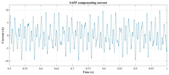
Figure 14.
SAPF compensating current for selective compensation case.
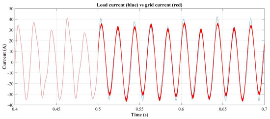
Figure 15.
Load vs. ac grid with SAPF starting at 500 ms.
In this case, to verify the proper performance of the selective compensation, the final values of the remaining components in the grid current are determined. After 200 ms of AC grid current acquisition (from 0.8 s to 1 s), a DFT followed by the grouping and filtering process is applied, yielding the components shown in Figure 16. Based on these results, a Kalman filter dimensioned according to the identified harmonic composition is applied, and the accurate magnitudes and frequencies are then obtained. It is confirmed that the low-frequency components of the AC grid current are, as expected, 32.5 A at 50.1 Hz and 3.03 A at 22 Hz. These results validate the proper operation of the SAPF combined with the proposed processes and algorithms.
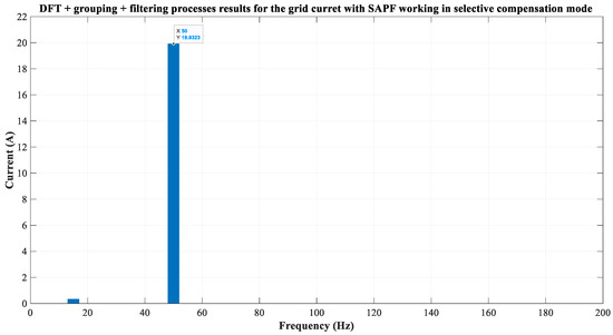
Figure 16.
Estimated ac grid current components during SAPF compensation in selective mode after DFT, grouping and filtering processes.
4.3. Case III. Increase in Number of Non-Fundamental Components During SAPF Operation
In this simulation, the operation of the SAPF is verified when an increase in the number of non-fundamental components in the load current occurs. This simulation starts with the same load current components defined in Table 2 and the global compensation for all non-fundamental components is then implemented. The load change occurs at t = 700 ms. The non-fundamental components then increase from 4 to 10. Their frequency and magnitude are shown in Table 4. The load current waveform is shown in Figure 17. It presents a THDi = 24.48%.

Table 4.
Load current components after its change at t = 0.7 s.
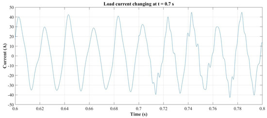
Figure 17.
Load current waveform changing at t = 0.7 s.
The change in the load current causes a deviation in the component estimation performed by the Kalman filter, as the increase in the number of components leads to an incorrect filter dimensioning and, consequently, loss of convergence in the internal states. As an example, Figure 18 shows the estimation of the 71.9 Hz component, where the real value is represented in red and the estimated one in blue. Similar behavior is observed for the other states. The instantaneous error between the estimated and measured load currents is continuously monitored to detect convergence failures, as shown in Figure 19. When this error exceeds the maximum allowable error (MAE) threshold defined in [37], the current control is disabled, and compensation is temporarily suspended. At that point, the component identification process is re-executed to determine the correct sizing of the Kalman filter matrices. Figure 20 illustrates the results of this re-identification process (DFT + grouping and filtering) before the Kalman filter restarts the estimation at t = 0.9 s. This sequence constitutes the filter reset mechanism described in Section 2, ensuring adaptive reconfiguration and stable estimation under varying load conditions.
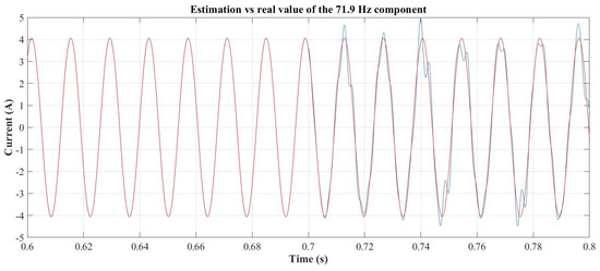
Figure 18.
Estimation of the 71.9 Hz component.
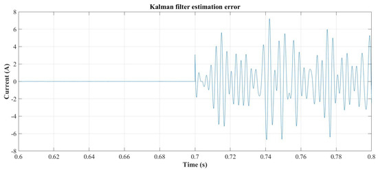
Figure 19.
Kalman filter estimation error.
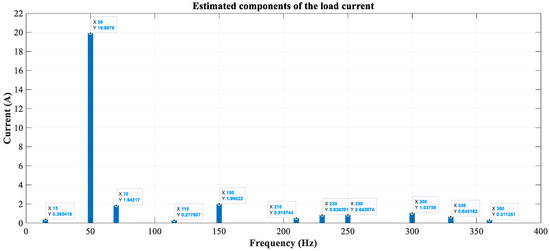
Figure 20.
New estimated components of the load current after grouping and filtering process.
The Kalman filter estimation converges at 1.16 s as can be seen from the evolution of the error signal in Figure 21. At this time, the reference current forming algorithm is started again. For this case, the theoretical value of IF_max is 23.76 A and, has been fixed at 18 A—and so forcing a different case for selective compensation. The least harmful components have been chosen to be components 5, 9, and 8 in descending order. The reference current forming algorithm eliminates these components, meaning that the new maximum compensating current is reduced to 17.4 A. As a result, components 5 and 9 will not be compensated and component 8 is scaled to use the remaining current capability of the SAPF. The algorithm computes kh8, which in this case results in:
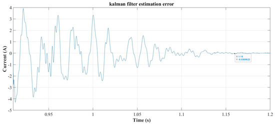
Figure 21.
Kalman filter estimation error after resizing its matrices for the new load.
The new reference current () is as follows:
Once the SAPF is again enabled, the resulting AC grid compensated current is shown in Figure 22. As expected, it maintains a non-sinusoidal shape due to the presence of the non-compensated components 5, 9, and 63% of component 8. The final THDi is equal to 11.73%.
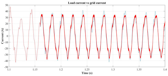
Figure 22.
Load (blue) vs. ac grid (red) current with SAPF starting at 1.16 s.
As in the preceding cases, to verify the effectiveness of the compensation achieved by the SAPF, a DFT of the compensated AC grid current is performed, followed by the grouping and filtering process. This results in the components shown in Figure 23. Using these values, the accurate magnitudes and frequencies were obtained with a properly dimensioned Kalman filter. The results confirmed the actual values of the AC grid current components: 32.5 A at 50.1 Hz, 2.98 A at 147.9 Hz, 1.06 A (63.6%) at 250.5 Hz, and 1.69 A at 300.7 Hz, as expected.
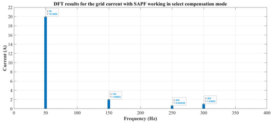
Figure 23.
Estimated components of the ac grid current during the selective compensation.
5. Practical Considerations for Real-Time Implementation
The proposed SAPF architecture and the HAKF-based identification method can be implemented in real-time hardware; however, several aspects must be considered to ensure stable and reliable operation under practical conditions. The methodology inherits an intrinsic structural delay from IEC 61000-4-7, which requires a 200 ms observation window for component identification. This window defines the minimum reaction time of the system after a change in the spectral composition of the load current. Although the DFT and the grouping–filtering stages are computationally light, the observation window itself cannot be reduced in applications requiring standard compliance.
After component re-identification, the Kalman filter is reconfigured and begins estimating the updated magnitudes and phases. During the convergence transient, these magnitudes evolve continuously. When full compensation does not exceed the maximum current capability of the SAPF, the reference current may be constructed directly from the estimated components, and compensation can be enabled even before Kalman convergence, since the reference-current generation is straightforward and does not involve component selection.
Selective compensation becomes necessary only when the total compensating current would exceed the converter limit. In this situation, the selective algorithm must determine which components should be attenuated or discarded and, if necessary, compute partial compensation coefficients. Because this selection must be based on stable and reliable magnitude estimates, applying it before Kalman convergence may lead to repeated re-evaluation of the selection logic, increased computational load, and fluctuations in the reference current. For this reason, the simulations apply selective compensation after the estimator reaches stable values.
In highly dynamic systems where the load current changes significantly within intervals shorter than the required observation window, it is possible that the stationary condition is never reached. In such cases, the SAPF may temporarily operate in a fallback mode based on the last valid set of current components or restricted to fundamental-only compensation, ensuring stable operation while avoiding the injection of incorrect harmonic references. When a new quasi-stationary interval is detected, the full identification procedure (sliding-window DFT, grouping and filtering, and Kalman estimation) is reinitiated to recover selective compensation capability. Alternative strategies—such as event-driven reconfiguration, tracking of DFT stability metrics, or adaptive thresholds for detecting transition periods—may reduce the delay associated with reconfiguration. These scenarios do not invalidate the proposed method, but they highlight practical considerations for applications subject to fast load variability.
From an implementation perspective, the computational requirements of the DFT, grouping–filtering, Kalman reconfiguration, and reference-current generation are compatible with digital signal processors commonly used in power electronics, such as TI C2000 series devices. The algorithmic structure is also suitable for FPGA-based implementations, where parallelization further reduces execution time. Hardware-in-the-loop (HIL) platforms, such as Typhoon HIL, provide a convenient environment for validating real-time performance, evaluating computational latency, and testing the algorithm under demanding dynamic conditions before deployment in physical hardware.
These considerations outline the main factors influencing real-time feasibility and motivate future work aimed at optimizing the identification stages, improving reaction time, and experimentally validating the proposed compensation strategy in DSP-based and HIL platforms.
6. Conclusions
Mitigating harmonic distortion has become a key research objective in efforts to enhance power quality. Shunt active power filters (SAPFs) have been widely employed to reduce the impact of current harmonics on electrical networks. However, the increasing presence of subharmonics and interharmonics introduces new challenges in current distortion correction. Since their frequencies are not integer multiples of the fundamental component, the identification and quantification of these components are non-trivial.
In this work, a single-phase SAPF specifically designed for harmonic and interharmonic filtering is presented. The proposed system requires precise identification of these components to achieve effective compensation performance. A method combining a discrete Fourier transform with grouping and filtering processes is used to properly configure a Kalman filter structure that extracts the real components of the load current. These components are obtained individually, enabling their selective compensation through the SAPF.
A reference-current generation algorithm is also proposed. This algorithm determines whether global compensation is feasible or whether selective compensation should instead be applied. In the latter case, it computes the weighting factors applied to the components, defining which ones must be compensated and to what extent. The simulation results presented in this work confirm the correct operation of the proposed SAPF, as well as the effectiveness of the selective compensation strategy under different load conditions.
The study also reveals several practical considerations relevant to real-time implementation. The identification stage is inherently limited by the 200 ms observation window required by IEC 61000-4-7, which defines the minimum reaction time of the method. In addition, when selective compensation is required, the component-selection algorithm must rely on stable magnitude estimates; therefore, its execution is more robust once the Kalman estimator has converged. These aspects do not affect the validity of the method, but they highlight the conditions under which selective operation becomes more demanding.
Although the proposed system has been implemented and validated in a single-phase configuration, the methodology can be extended to three-phase four-wire networks, where each phase may be treated as an independent single-phase system. Future work will address the application of the approach to three-phase SAPFs, its validation in real-time DSP platforms, and the evaluation of dynamic performance using hardware-in-the-loop environments to assess execution time, convergence behavior, and practical feasibility under realistic operating conditions.
Author Contributions
Conceptualization, G.M.-N. and S.O.-G.; methodology, G.M.-N. and S.O.-G.; software, G.M.-N.; validation, G.M.-N.; formal analysis, G.M.-N. and S.O.-G.; investigation, G.M.-N.; resources, S.O.-G.; writing—original draft preparation, G.M.-N.; writing—review and editing, G.M.-N. and S.O.-G.; visualization, G.M.-N. and S.O.-G.; supervision, S.O.-G. All authors have read and agreed to the published version of the manuscript.
Funding
This research received no external funding.
Institutional Review Board Statement
Not applicable.
Informed Consent Statement
Not applicable.
Data Availability Statement
No new data were created or analyzed in this study. Data sharing is not applicable to this article.
Conflicts of Interest
The authors declare no conflict of interest.
References
- Ravindran, V.; Rönnberg, S.K.; Bollen, M.H. Interharmonics in PV systems: A review of analysis and estimation methods; considerations for selection of an APT method. IET Renew. Power Gener. 2019, 13, 2023–2032. [Google Scholar] [CrossRef]
- Zhong, Q.; Qiu, Y.; Zhao, Y.; Li, H.; Wang, G.; Wen, F. Interharmonic Analysis Model of Photovoltaic Grid-connected System with Extended Dynamic Phasors. J. Mod. Power Syst. Clean Energy 2021, 9, 1540–1547. [Google Scholar] [CrossRef]
- Monteiro, H.L.M.; Camponogara, Â.; Ribeiro, M.V.; Duque, C.A.; Poor, H.V. A DFT-based method for estimating interharmonics in wind power generation. IET Smart Grid 2022, 5, 332–346. [Google Scholar] [CrossRef]
- Bollen, M.H.J.; Cundeva, S.; Ronnberg, S.K.; Wahlberg, M.; Yang, K.; Yao, L. A wind park emitting characteristic and non-characteristic harmonics. In Proceedings of the 14th International Power Electronics and Motion Control Conference (EPE/PEMC 2010), Ohrid, Macedonia, 6–8 September 2010; pp. S14-22–S14-26. [Google Scholar]
- Arranz-Gimon, A.; Zorita-Lamadrid, A.; Morinigo-Sotelo, D.; Duque-Perez, O. A Review of Total Harmonic Distortion Factors for the Measurement of Harmonic and Interharmonic Pollution in Modern Power Systems. Energies 2021, 14, 6467. [Google Scholar] [CrossRef]
- Miletić, M.; Raguž, K.R.; Zeleničić, V.; Erceg, I.; Sumina, D. Development of Single-Phase Shunt Active Power Filter for Reduction of Current Harmonics in Data Center Power System. In Proceedings of the 2023 11th International Conference on Smart Grid (icSmartGrid), Paris, France, 4–7 June 2023; pp. 1–7. [Google Scholar]
- IEC 61000-4-7; Electromagnetic Compatibility (EMC)-Part 4: Testing and Measurement Techniques—General Guide on Harmonics and Interharmonics Measurements and Instrumentation, for Power Supply Systems and Equipment Connected Thereto. International Electrotechnical Commission: Geneva, Switzerland, 2002; pp. 1–8. Available online: https://standards.iteh.ai/catalog/standards/clc/73571ff6-97d0-4c1e-a019-7d0dfe1552ff/en-61000-4-7-2002-a1-2009 (accessed on 22 September 2025).
- IEEE Std 519-2014 (Revision of IEEE Std 519-1992); IEEE Recommended Practice and Requirements for Harmonic Control in Electric Power System. IEEE: Piscataway, NJ, USA, 2014; pp. 1–29. [CrossRef]
- IEEE Std 1459–2010; IEEE Standard Definitions for the Measurement of Electric Power Quantities Under Sinusoidal, Nonsinusoidal, Balanced, or Unbalanced Conditions. IEEE: New York, NY, USA, 2010.
- Akagi, H. Active harmonic filters. Proc. IEEE 2005, 93, 2128–2141. [Google Scholar] [CrossRef]
- Subramanian, N.; Stonier, A.A. A Comprehensive Review on Selective Harmonic Elimination Techniques and its Permissible Standards in Electrical Systems. IEEE Access 2024, 12, 141966–141998. [Google Scholar] [CrossRef]
- Hoon, Y.; Radzi, M.A.M.; Hassan, M.K.; Mailah, N.F. Control Algorithms of Shunt Active Power Filter for Harmonics Mitigation: A Review. Energies 2017, 10, 2038. [Google Scholar] [CrossRef]
- Li, D.; Wang, T.; Pan, W.; Ding, X.; Gong, J. A comprehensive review of improving power quality using active power filters. Electr. Power Syst. Res. 2021, 199, 107389. [Google Scholar] [CrossRef]
- Orts-Grau, S.; Gimeno-Sales, F.J.; Abellan-Garcia, A.; Segui-Chilet, S.; Alfonso-Gil, J.C. Improved Shunt Active Power Compensator for IEEE Standard 1459 Compliance. IEEE Trans. Power Deliv. 2010, 25, 2692–2701. [Google Scholar] [CrossRef]
- Pereira, H.A.; da Mata, G.L.; Xavier, L.S.; Cupertino, A.F. Flexible harmonic current compensation strategy applied in single and three-phase photovoltaic inverters. Int. J. Electr. Power Energy Syst. 2019, 104, 358–369. [Google Scholar] [CrossRef]
- Chilipi, R.R.; Al Sayari, N.; Alsawalhi, J.Y. Control of single-phase solar power generation system with universal active power filter capabilities using least mean mixed-norm (LMMN)-based adaptive filtering method. IEEE Trans. Sustain. Energy 2020, 11, 879–893. [Google Scholar] [CrossRef]
- Hekss, Z.; Abouloifa, A.; Lachkar, I.; El Aroudi, A.; Echalih, S.; Al-Numay, M.; Giri, F. Advanced nonlinear controller of single-phase shunt active power filter interfacing solar photovoltaic source and electrical power grid. Int. Trans. Electr. Energy Syst. 2021, 31, e13237. [Google Scholar] [CrossRef]
- Komurcugil, H.; Bayhan, S.; Guler, N.; Blaabjerg, F. An Effective Model Predictive Control Method with Self-Balanced Capacitor Voltages for Single-Phase Three-Level Shunt Active Filters. IEEE Access 2021, 9, 103811–103821. [Google Scholar] [CrossRef]
- Muñoz-Galeano, N.; Orts-Grau, S.; Seguí-Chilet, S.; Gimeno-Sales, F.J.; López-Lezama, J.M. Deterministic Algorithm for Selective Shunt Active Power Compensators According to IEEE Std. 1459. Energies 2017, 10, 1791. [Google Scholar] [CrossRef]
- Miret, J.; Castilla, M.; Matas, J.; Guerrero, J.M.; Vasquez, J.C. Selective harmonic-compensation control for single-phase active power filter with high harmonic rejection. IEEE Trans. Ind. Electron. 2009, 56, 3117–3127. [Google Scholar] [CrossRef]
- Chen, C.-I.; Chen, Y.-C. Comparative study of harmonic and interharmonic estimation methods for stationary and time-varying signals. IEEE Trans. Ind. Electron. 2014, 61, 397–404. [Google Scholar] [CrossRef]
- Mao, M.; Tang, Y.; Chen, J.; Xu, Z.; Sun, H.; Yin, C. Monitoring and Suppression Strategies of the Interharmonic in the Grid-Connected Photovoltaic System: A Review. Energies 2025, 18, 3426. [Google Scholar] [CrossRef]
- Jain, S.K.; Singh, S.N. Exact model order ESPRIT technique for harmonics and interharmonics estimation. IEEE Trans. Instrum. Meas. 2012, 61, 1915–1923. [Google Scholar] [CrossRef]
- Gong, J.; Liu, S. A Harmonic and Interharmonic Detection Method for Power Systems Based on Enhanced SVD and the Prony Algorithm. Appl. Sci. 2023, 13, 7558. [Google Scholar] [CrossRef]
- Sheshyekani, K.; Fallahi, G.; Hamzeh, M.; Kheradmandi, M. A General Noise-Resilient Technique Based on the Matrix Pencil Method for the Assessment of Harmonics and Interharmonics in Power Systems. IEEE Trans. Power Deliv. 2017, 32, 2179–2188. [Google Scholar] [CrossRef]
- Mishra, A.; Deokar, S.A. A Transformerless Single Phase Shunt Active Hybrid Power Filter for Power Quality Improvement for Electrified Transportations. In Proceedings of the 2017 International Conference on Current Trends in Computer, Electrical, Electronics and Communication (CTCEEC), Mysore, India, 8–9 September 2017; pp. 398–404. [Google Scholar]
- Gallo, D.; Langella, R.; Testa, A. On the processing of harmonics and interharmonics in electrical power systems. In Proceedings of the 2000 IEEE Power Engineering Society Winter Meeting. Conference Proceedings (Cat. No.00CH37077), New York, NY, USA, 23–27 January 2000; pp. 1581–1586. [Google Scholar]
- Harris, F.J. On the use of windows for harmonic analysis with the discrete Fourier transform. Proc. IEEE 1978, 66, 51–83. [Google Scholar] [CrossRef]
- Pan, X.; Zhang, L.; Huang, H. Harmonic Cancellation by Adaptive Notch Filter Based on Discrete Wavelet Packet Transform for an MMCC-STATCOM. IEEE Trans. Power Deliv. 2022, 37, 1834–1844. [Google Scholar] [CrossRef]
- Barros, J.; Diego, R.I. Analysis of harmonics in power systems using the wavelet-packet transform. IEEE Trans. Instrum. Meas. 2008, 57, 63–69. [Google Scholar] [CrossRef]
- Yu, Y.; Zhao, W.; Li, S.; Huang, S. A Two-Stage Wavelet Decomposition Method for Instantaneous Power Quality Indices Estimation Considering Interharmonics and Transient Disturbances. IEEE Trans. Instrum. Meas. 2021, 70, 3052554. [Google Scholar] [CrossRef]
- Liu, S. An adaptive Kalman filter for dynamic estimation of harmonic signals. In Proceedings of the 8th International Conference on Harmonics and Quality of Power. Proceedings (Cat. No.98EX227), Athens, Greece, 15–18 October 2024; pp. 636–640. [Google Scholar]
- Garanayak, P.; Panda, G. Fast and accurate measurement of harmonic parameters employing hybrid adaptive linear neural network and filtered-x least mean square algorithm. IET Gener. Transm. Distrib. 2016, 10, 421–436. [Google Scholar] [CrossRef]
- Garanayak, P.; Naayagi, R.T.; Panda, G. A High-Speed Master-Slave ADALINE for Accurate Power System Harmonic and Inter-Harmonic Estimation. IEEE Access 2020, 8, 51918–51932. [Google Scholar] [CrossRef]
- Worrall, D.E.; Garbin, S.J.; Turmukhambetov, D.; Brostow, G.J. Harmonic Networks: Deep Translation and Rotation Equivariance. In Proceedings of the 2017 IEEE Conference on Computer Vision and Pattern Recognition (CVPR), Honolulu, HI, USA, 21–26 July 2017; pp. 7168–7177. [Google Scholar]
- Ulicny, M.; Krylov, V.A.; Dahyot, R. Harmonic convolutional networks based on discrete cosine transform. Pattern Recognit. 2022, 129, 108707. [Google Scholar] [CrossRef]
- Martínez-Navarro, G.; Orts-Grau, S.; Alfonso-Gil, J.C.; Balaguer-Herrero, P. Synchronized Measurement of the Fundamental Voltage and Harmonic, Interharmonic, and Subharmonic Components of the Electrical Grid Using an Adaptive Kalman Filter. Appl. Sci. 2024, 14, 8669. [Google Scholar] [CrossRef]
- Alshawawreh, J. Adaptive technique based on fast fourier transform for selecting the modelled harmonics’ orders in Kalman filter. Prz. Elektrotechniczny 2018, 94, 95–100. [Google Scholar] [CrossRef]
- Guo, J.; Jiang, C.; Guan, C.; Zhang, T.; Pu, J. Modeling and Simulation of Power Grid Voltage Harmonic Detection Method Based on Adaptive Kalman Filter. In Proceedings of the 2021 33rd Chinese Control and Decision Conference (CCDC), Kunming, China, 22–24 May 2021; pp. 6166–6172. [Google Scholar]
- Orts-Grau, S.; Alfonso-Gil, J.; Balaguer-Herrero, P.; Martínez-Navarro, G.; Gimeno-Sales, F. Generalized one-cycle current controller for improved SAPF power quality management. Int. J. Electr. Power Energy Syst. 2024, 157, 109833. [Google Scholar] [CrossRef]
Disclaimer/Publisher’s Note: The statements, opinions and data contained in all publications are solely those of the individual author(s) and contributor(s) and not of MDPI and/or the editor(s). MDPI and/or the editor(s) disclaim responsibility for any injury to people or property resulting from any ideas, methods, instructions or products referred to in the content. |
© 2025 by the authors. Licensee MDPI, Basel, Switzerland. This article is an open access article distributed under the terms and conditions of the Creative Commons Attribution (CC BY) license (https://creativecommons.org/licenses/by/4.0/).