1. Introduction
Autonomous driving technology is in a rapid development phase, with the core challenge being to build perception capabilities that are accurate, reliable, and real-time for the surrounding environment [
1,
2]. Among many sensing modalities, the visual system plays a crucial role due to its ability to provide rich semantic information (such as traffic signs, lane markings, and traffic lights) and its relatively low cost [
3,
4,
5]. In particular, stereo vision technology, by mimicking the human eyes’ disparity principle, can directly recover the three-dimensional depth information of a scene from images, providing indispensable spatial geometric understanding for key tasks such as vehicle navigation, obstacle avoidance, and path planning [
6,
7].
However, traditional automotive stereo vision systems still face significant challenges in complex and variable real-world road scenarios [
8,
9,
10]: they exhibit deficiencies in depth coverage, dynamic range, occlusion handling, texture robustness, real-time performance, and calibration stability. Specifically, the limited baseline length and image resolution make the depth estimation for distant objects and low-texture regions unstable, making it difficult to achieve reliable long-range perception in high-speed scenarios; the dynamic range is insufficient under extreme lighting conditions such as strong contrasts, tunnels, and nighttime, easily causing overexposure or underexposure and affecting feature extraction and matching; fixed viewpoints lead to more occlusion-related blind spots and hinder recovery of depth information for occluded objects; texture gaps or repetitive textures can cause matching errors and degrade depth robustness; processing high-resolution images imposes substantial computational load, making it challenging for embedded automotive platforms to simultaneously meet real-time and accuracy requirements; moreover, sensitivity to camera calibration and geometric consistency can reduce depth stability with even small errors. In summary, the bottlenecks of stereo systems primarily stem from the limited baseline/viewpoint, which constrains coverage and robustness, and the resultant challenges related to lighting, occlusion, texture, and computational resources. By contrast, tri-camera stereo vision can effectively address these bottlenecks faced by conventional stereo vision systems. For tri-camera systems, the stability of stereo imaging is particularly important [
11,
12]. However, in real-world conditions, temperature extremes in automotive environments can cause deformation of the cameras, leading to optical axis offsets and consequently degrading imaging accuracy and stability.
Current research on schemes to resist environmental-induced thermal expansion and contraction (TAC)-related deformation of cameras is relatively limited. This paper explores resisting environmental-induced camera deformation through material design and structural design to reduce imaging errors and improve stability. First, camera structural components are mainly aluminum alloys; however, different aluminum alloys exhibit large variations in mechanical properties such as strength and toughness [
13,
14,
15,
16], leading to differing resistance to deformation. Second, some scholars study heterogeneous structures to enhance the strength and toughness of structural components; specifically, composites formed by combining high-strength and high-toughness materials can, during deformation, generate heterogeneous deformation-induced forces that oppose further deformation, thereby enhancing the strength and toughness [
17,
18,
19,
20]. Additionally, cellular (honeycomb) structures distribute material efficiently along load paths through clever geometric design, enabling amplification of material performance [
21,
22,
23,
24]. The core mechanical advantages include excellent specific strength, high specific stiffness, and unparalleled energy absorption efficiency, and they may even enable parts to resist deformation. In summary, through material design, heterogeneous structure design, and honeycomb structure design, it may be possible to achieve deformation-resistant capabilities in structural components. However, current studies on material design and structural design to improve a camera’s resistance to deformation for ensuring tri-camera stereo imaging accuracy and stability are relatively limited.
This paper studies the influence of different aluminum alloy materials, heterogeneous structures, and honeycomb structures on the deformation resistance of tri-camera systems. An Abaqus software (Abaqus 2016)-based finite element analysis is used to evaluate the deformation resistance of cameras prepared with different materials and structures under various environmental conditions. Additionally, we perform field experiments to obtain the deformation resistance of cameras made from different materials under different environmental conditions. The results from the field experiments and the finite element analysis validate the effectiveness of the FE analysis. This work is conducive to improving the imaging accuracy and stability of tri-camera stereo vision for automotive onboard applications, and it advances perception capabilities in autonomous driving toward higher safety levels.
2. Tri-Camera Stereo Vision Imaging System
Monocular distance measurement uses a single camera (Shanghai, China) to estimate distance [
25,
26]. Its core principle is the assumption that the target object and the vehicle are on the same horizontal plane. First, advanced image recognition techniques (such as object detection algorithms) precisely identify the target object and obtain its bounding box, with particular emphasis on accurately locating the bottom edge where the object touches the ground. Then, distances are computed using the pinhole camera model and the principle of triangle similarity: the longitudinal distance mainly depends on the camera mounting height (
h), focal length (
f), and the object’s pixel height in the image (
Hpixel). The formula is: Actual distance = (
h ×
f)/
Hpixel. The lateral distance is derived from the horizontal pixel position of the object in the image to compute the lateral offset. However, this method has significant limitations: its accuracy heavily relies on the assumption that the target and the vehicle share the same plane on the ground. When the ground is uneven, the target is not in contact with the ground (e.g., the vehicle is elevated), or the camera tilts due to vehicle acceleration, deceleration, or jolts, the distance measurements can fail badly. Additionally, it is extremely sensitive to pixel-level errors; for example, with a 1.3 MP camera (1280 × 960), a horizontal field of view of 52°, and a vertical FOV of 38°, at a target distance of 100 m, a one-pixel error can theoretically cause about a 5% distance error (not accounting for pose changes and image distortion). The main advantages of monocular distance measurement are low hardware cost (only one camera), relatively low computational complexity allowing real-time performance, and mature, easy-to-deploy algorithms. The main drawbacks are reliance on strict environmental assumptions leading to poor robustness, large error amplification at long distances, and the need for frequent calibration to compensate for camera pose changes.
Stereo vision ranging uses two horizontally placed cameras (forming a stereo system) to emulate human binocular vision [
27]. Its core principle is to compute the horizontal disparity
d of the same target point on the image planes of the left and right cameras. After precisely matching corresponding pixels in the left and right images, and using triangle geometry along with the known baseline distance
b (the horizontal distance between the optical centers) and the camera focal length f, the depth (distance)
zw of the target point can be directly calculated: z
w = (
f ×
b)/
d. Ultimately, the system can compute a depth value for every pixel (or matched point) in the image, generating a depth map that corresponds pixel-for-pixel to the original RGB image; this depth information can be directly used for higher-level tasks such as object recognition. The main advantage of stereo ranging is that it does not rely on a ground-plane assumption and can directly obtain physical 3D information about objects in the scene, providing high accuracy at near to mid distances (typical error < 5%) and rich environment depth maps to support 3D perception. Its main drawbacks are higher hardware cost (two cameras that must be tightly synchronized and calibrated), higher computational complexity (dense stereo matching requires substantial processing), sensitivity to scene texture (matching can fail in low-light, reflective, or textureless regions), and more complex calibration with the baseline needing to be kept stable (mechanical drift can degrade precision or cause failure). In addition to the above, it should be emphasized that the unit of
d is pixels. Each pixel is about 2∼4 μm. Compared with
f and
b,
d is a very small quantity, so the error in
d has the greatest impact on the error in
z. The error in
d is mainly determined by (i) the accuracy of the stereo measurement algorithm and (ii) the imaging stability of the stereo cameras (the image positions and the optical axes of the left and right cameras experience micro-deformations under different temperatures), i.e.,
d =
da +
do. Assuming the algorithm accuracy da remains constant, the long-term measurement stability and accuracy of the stereo cameras are governed by
do. Moreover, a camera with 1 million pixels (pixel size 4.2 μm) has a naturally smaller
do than an 8-million-pixel camera (pixel size 2.1 μm); under the same structure,
do1m = 2
do8m. Therefore, the theoretical error-control difficulty for an 8 M stereo pair is twice that of a 1 M pair, and adding an additional telephoto monocular camera in the middle would increase the difficulty again.
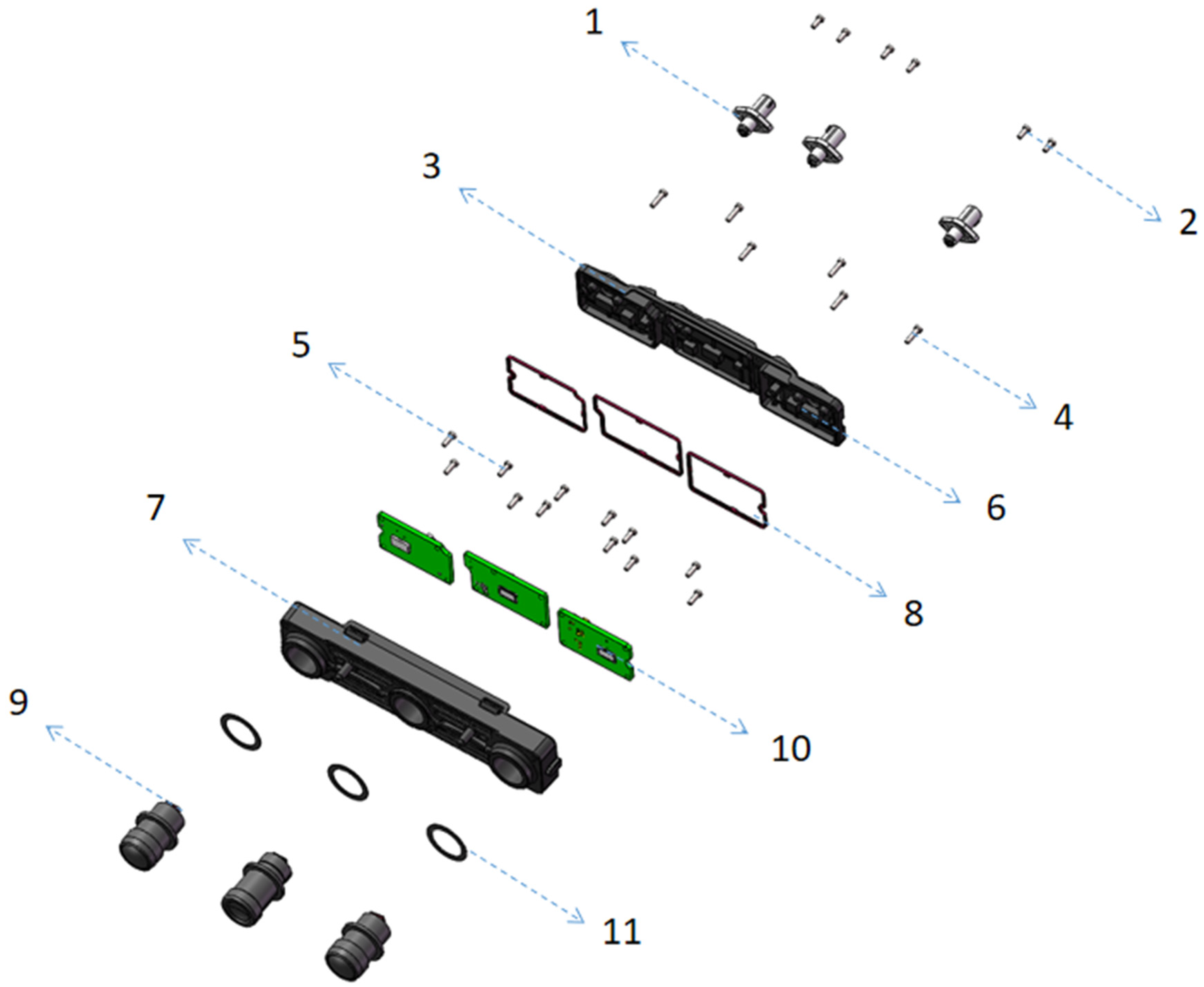
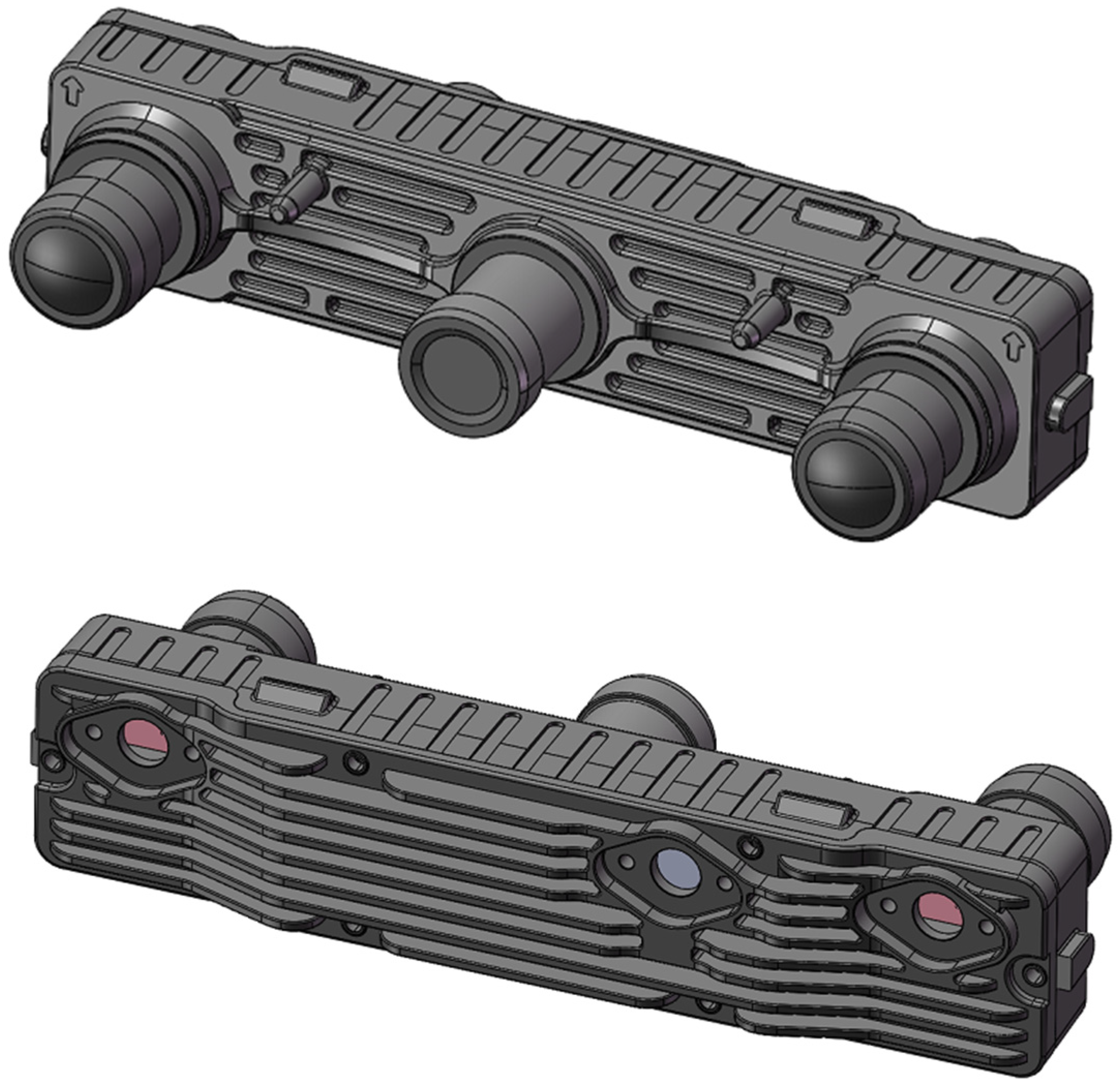
Based on monocular and stereo ranging principles, we designed a tri-camera configuration for in-vehicle autonomous driving applications. We adopt an integrated body design, fixing three lenses onto a single complete front housing. This housing serves both as the tri-camera support and as the mount for the monocular cameras. The integrated design enhances the overall stability of the left and right camera modules and helps prevent differential micro-deformations among the three modules that can occur if they share a single support, which would otherwise affect the stereo optical axis synchronization stability. In addition, the tri-camera system we designed comprises a long-telephoto monocular with a horizontal field of view of 30° (15 mm), and two wide-angle cameras with horizontal fields of view of 120° on the left and right. That is, the telephoto monocular can detect targets of interest such as vehicles at distances of about 350–500 m, while the left and right 120° wide-angle binoculars provide a 3D stereo vision that can see up to about 150 m. This setup also covers side oncoming traffic in turning scenarios (meeting CNCAP 2025 test scene requirements) and enables the detection of obstacles of any size at close range. It represents an optimal design for a forward-looking camera. The components forming the tri-camera are shown in
Figure 1, and the names and materials of the tri-camera components are listed in
Table 1.
Advantages of our tri-camera design:
(1) Integrated housing: instead of each monocular and stereo pair having its own housing and then being fixed to a separate bracket, we use an integrated housing. The goal is to reduce relative changes between multiple structures. (Our other binocular cameras use separate housings, but the trinocular design adds a central module, so the strength of the intermediate fixed bracket may be insufficient.) The design concept converges with Tesla’s integrated body approach.
(2) All three lenses must sit at the same height. The benefit is that the front frame of the trinocular housing can be flat, making the entire housing symmetrical around the central axis. This aims to achieve more symmetric thermal management, i.e., consistent heat dissipation between left and right sides (if an exact left–right cooling balance is not possible, we at least keep the temperature changes on both sides as similar as possible).
(3) In the honeycomb structure design, we can add stiffening ribs to maintain overall rigidity among the left, middle, and right sections, preventing deformation of the middle module from causing twisting of the left or right sides (i.e., micro-deformations that would create misalignment). When twisting occurs, the resulting change could be only a few pixels. The current structural design of the tri-camera system is the optimal structure after our theoretical analysis, simulation validation, and experimental verification. The specific design details of the structural morphology will be discussed in a separate paper.
Overall, the advantages can be summarized as: maintains overall strength; maximizes left–right symmetry and support, reduces micro-deformation of individual modules relative to the trinocular module (achieved with an integrated housing).
Due to long-term exposure to high and low temperatures (over a ten-year period, the camera mounted on a vehicle will undergo thousands of cycles of temperatures from −40 °C to 95 °C), the internal components of the camera undergo natural deformation (thermal expansion and contraction), causing changes in the camera’s intrinsic parameters. This leads to degradation in stereo ranging and excessive ranging error: a one-pixel shift in the optical centers of the left and right cameras, given a BF value of about 200,000 corresponds to a true distance of 10 m with a disparity of 2 pixels, resulting in a relative error change of about 50%. To reduce the ranging bias of the tri-camera system and improve the stability of stereo imaging, this paper investigates camera material design, heterogeneous structure design, and honeycomb structure design to mitigate deformation caused by thermal expansion and contraction during operation, thereby reducing tri-camera ranging bias and enhancing stereo imaging stability.
3. Design Optimization of Materials and Structure for Tri-Camera
3.1. Numerical Implementation Details
This study addresses the structural-thermal coupling problem within a weakly coupled sequential framework, where the mathematical foundation consists of two sets of governing equations: steady-state heat conduction and small deformation linear elasticity. First, the steady-state thermal field is solved, and the temperature distribution
T satisfies:
And convective heat transfer and boundary conditions such as assigned temperatures are applied, specifically as follows:
where
is the temperature-dependent thermal conductivity,
is the volumetric heat source intensity,
is the convective heat transfer coefficient,
is the ambient temperature. Subsequently, the obtained temperature field is input as a thermal load into the linear elastic equation. Considering the thermal strain term, the displacement field
u and the stress field
σ satisfy:
where
α(
T) is the thermal expansion coefficient,
C is the isotropic elastic stiffness tensor defined by
E(
T) and
ν, and
I is the second-order identity tensor. This sequential coupling strategy can effectively separate the computational complexity of the thermal and structural fields while maintaining numerical stability.
To ensure accurate resolution of temperature and deformation gradients, this paper adopts a differentiated strategy in finite element discretization and element type selection. For the thermal field, quadratic tetrahedral thermal elements (10-node, quadratic interpolation) are used in regions with significant temperature gradients to improve field interpolation accuracy. Conversely, linear tetrahedra are employed in block regions with gentle gradients to control degrees of freedom and enhance computational efficiency. For the structural field, quadratic tetrahedral elastic elements (Quadratic TET, with reduced integration and hourglass control) are chosen as the primary element type to balance accuracy and robustness. For localized thin-walled components, additional mesh sensitivity studies are performed using shell elements to evaluate the impact of thickness-direction discretization on the response.
The solution process was implemented on the Abaqus 2023 platform. For the steady-state thermal field, either a sparse direct solver or a preconditioned conjugate gradient (PCG) iterative solver was employed, with a convergence criterion of a relative residual less than 10−8 to ensure high accuracy in the temperature distribution. For the structural field, a linear static analysis was performed, utilizing the GMRES iterative solver with a multigrid preconditioner. A dual convergence criterion, based on both the displacement increment norm and the force residual, was set to be less than 10−7, striking a balance between numerical stability and computational cost. The coupling strategy was a sequential mapping approach: the thermal field was solved first, and then the temperature field was mapped to the structural mesh via volume-conserving interpolation. When the material parameters were temperature-sensitive, 2–3 relaxation iterations were performed on the outer loop to achieve consistency between the material properties and the field quantities, avoiding the amplification of errors caused by parameter lag.
It should be noted that several conclusions regarding the advantages and disadvantages of heterogeneous and cellular structures are primarily derived from numerical modeling and simulation inferences and have not yet been validated by corresponding physical experiments within the scope of this paper. We have explicitly listed this limitation in the discussion and conclusion sections. This limiting statement helps readers accurately understand the evidentiary boundaries of the conclusions presented in this paper and provides direction for the experimental design and optimization of future research.
3.2. Analysis Procedure for Camera Deformation
This paper studies camera material design, heterogeneous structure design, and honeycomb structure design to reduce deformation caused by thermal expansion and contraction during camera operation. Among them, the electrical performance remains constant, such as device code, power consumption, etc. The environmental temperature interval remains unchanged, and three temperature points (−40 °C, 25 °C, 95 °C) are used.
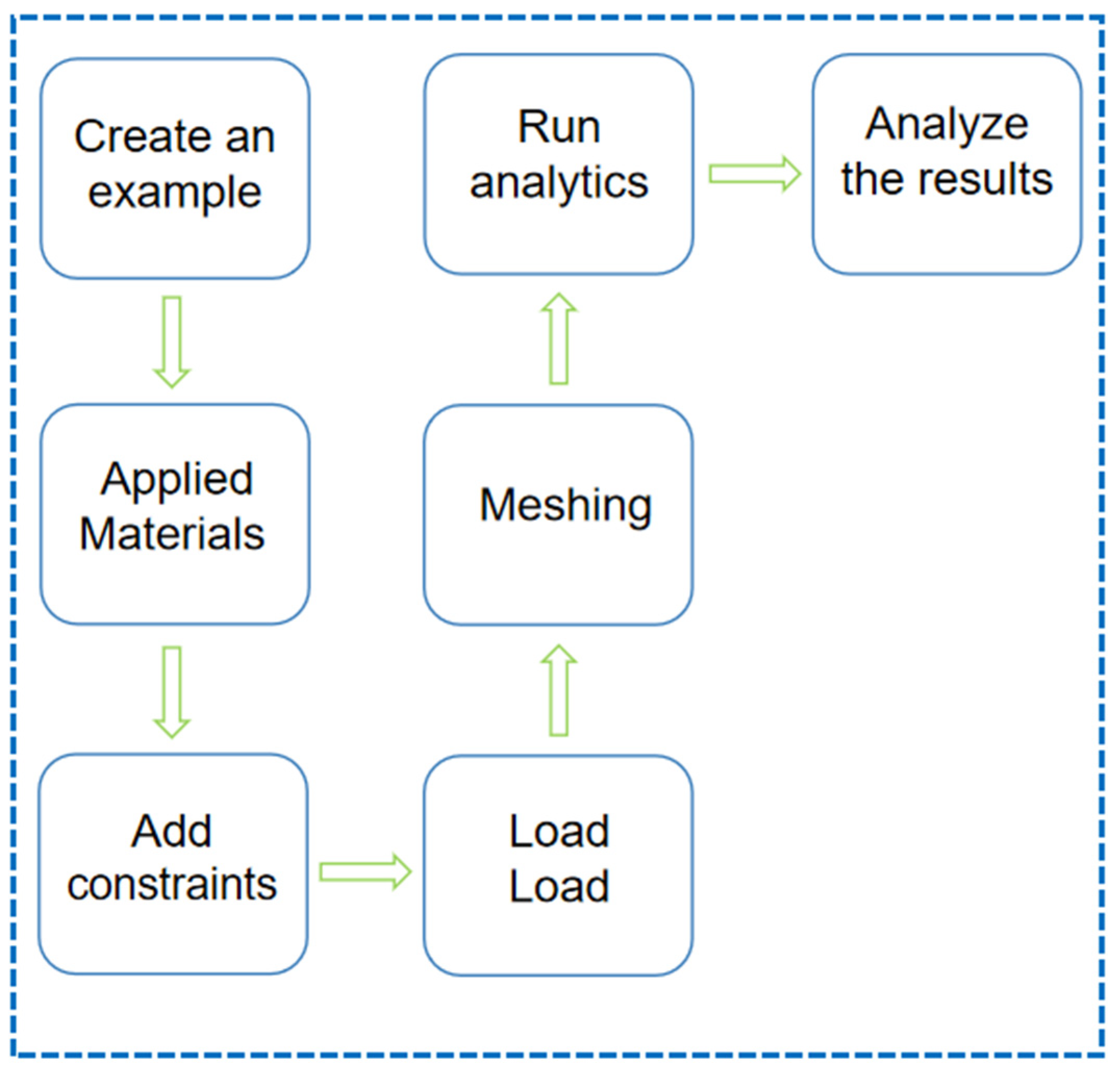
The changes in camera deformation brought by different materials and structure optimization designs are investigated through finite element analysis (FEA) using Abaqus. The finite element analysis steps for deformation caused by thermal expansion and contraction due to ambient temperature are shown in
Figure 2. Analysis process:
(1) Create examples: Define the camera assembly and create analysis instances for each design scenario (material baseline, heterogeneous bilayer, honeycomb). Each instance corresponds to one FEA model with three steady temperature load cases. The assembly includes housing, lens seat, fasteners or equivalent boundary features, ensuring consistent reference geometry for cross-scenario comparison.
(2) Apply materials: Assign material properties to each part according to the design scheme. For homogeneous designs, use the selected aluminum alloy dataset; for heterogeneous designs, assign distinct datasets to hard/soft zones and define perfectly bonded interfaces. Record the source and nominal ranges of elastic modulus, Poisson’s ratio, thermal expansion coefficient, and thermal conductivity. Perform a brief sensitivity check for key parameters to confirm robustness of the ranking among material options.
(3) Add constraints: Replicate the real mounting strategy by constraining installation holes or pads to prevent rigid-body motion while avoiding over-constraining. Use symmetry or reference planes only when geometrically valid. Allow non-critical degrees of freedom consistent with the physical fixture (e.g., tangential freedom) to mitigate spurious stresses. Document the chosen constraint set so that it is reproducible across all scenarios.
(4) Set Conditions: Set the environmental temperature conditions at −40 °C, 25 °C, and 95 °C. For each load case, solve the steady temperature distribution and then the corresponding thermo-elastic response driven by thermal expansion. No additional mechanical forces are applied, so that the deformation differences are attributable to materials and geometry.
(5) Divide the grid: Seed the global mesh at 1.0–2.0 mm, refine to 0.5–1.0 mm around lens seats, thin ribs, fillets, and heterogeneous interfaces. Check mesh quality metrics (distortion, aspect ratio) and adjust local seeds or partition geometry when needed. Conduct a three-level mesh independence study; accept the mesh when key responses vary by less than 3% between the last two levels.
(6) Operational analysis: Solve each steady load case with Abaqus. Extract nodal displacements on the optical reference features to compute axial deviation and tilt of the camera modules. Map stresses to identify hotspots near interfaces and mounting regions. Aggregate results across the three temperatures to form a comparative table for all design schemes.
(7) Analysis results: Interpret the results of the analysis and provide a report.
In addition, the finite element analysis requires the following assumptions:
(1) The camera deformation is much smaller than the structure dimensions, suitable for geometric linear analysis, with no geometric nonlinearity to be considered.
(2) The temperature field of the camera is steady (steady-state).
(3) The material is isotropic and defect-free, with ideal bonded interfaces and no relative sliding.
(4) Air convection, radiative heat transfer, and other external exchanges are neglected; only fixed temperature boundary conditions are applied.
3.3. Materials Optimization Design
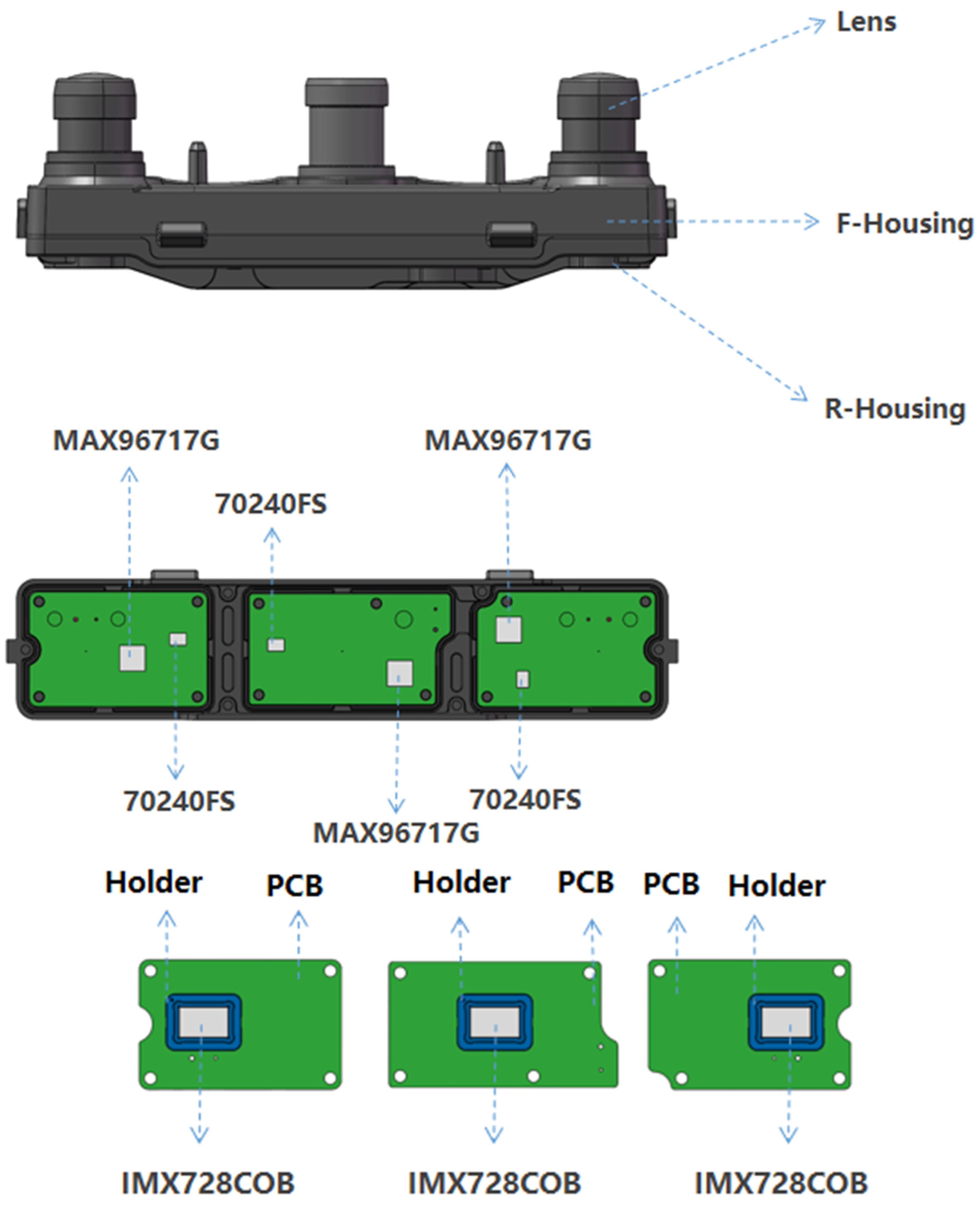
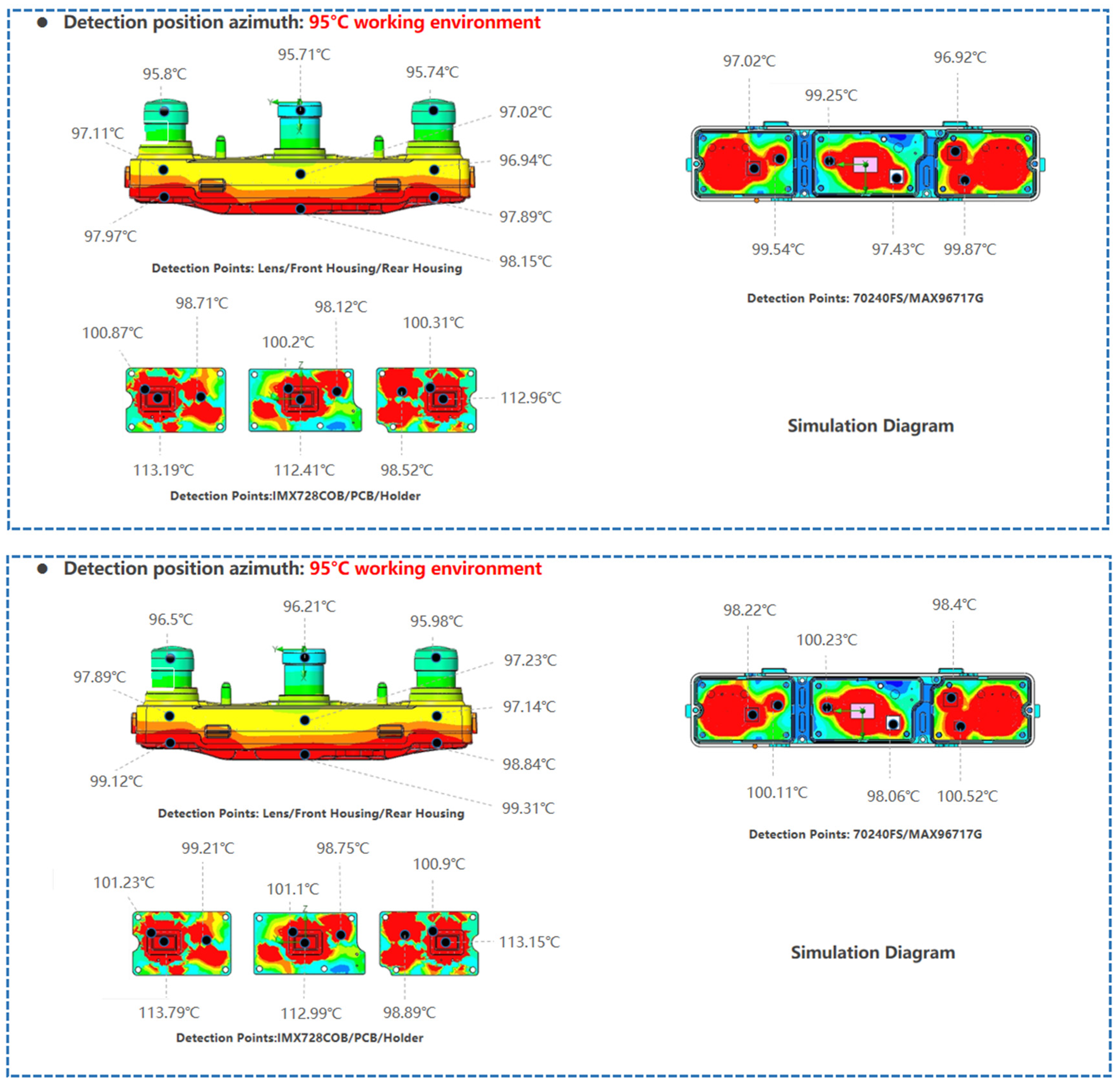
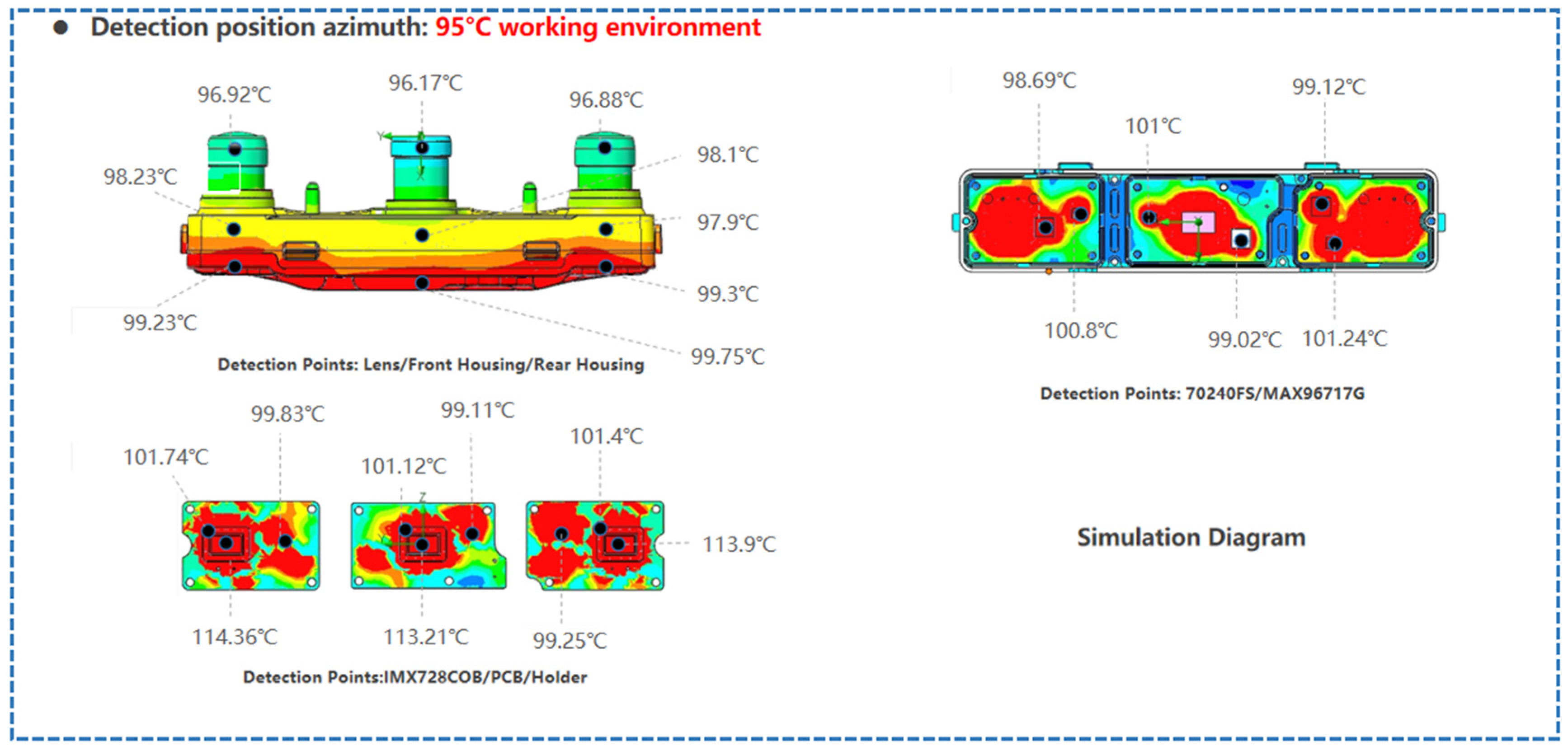
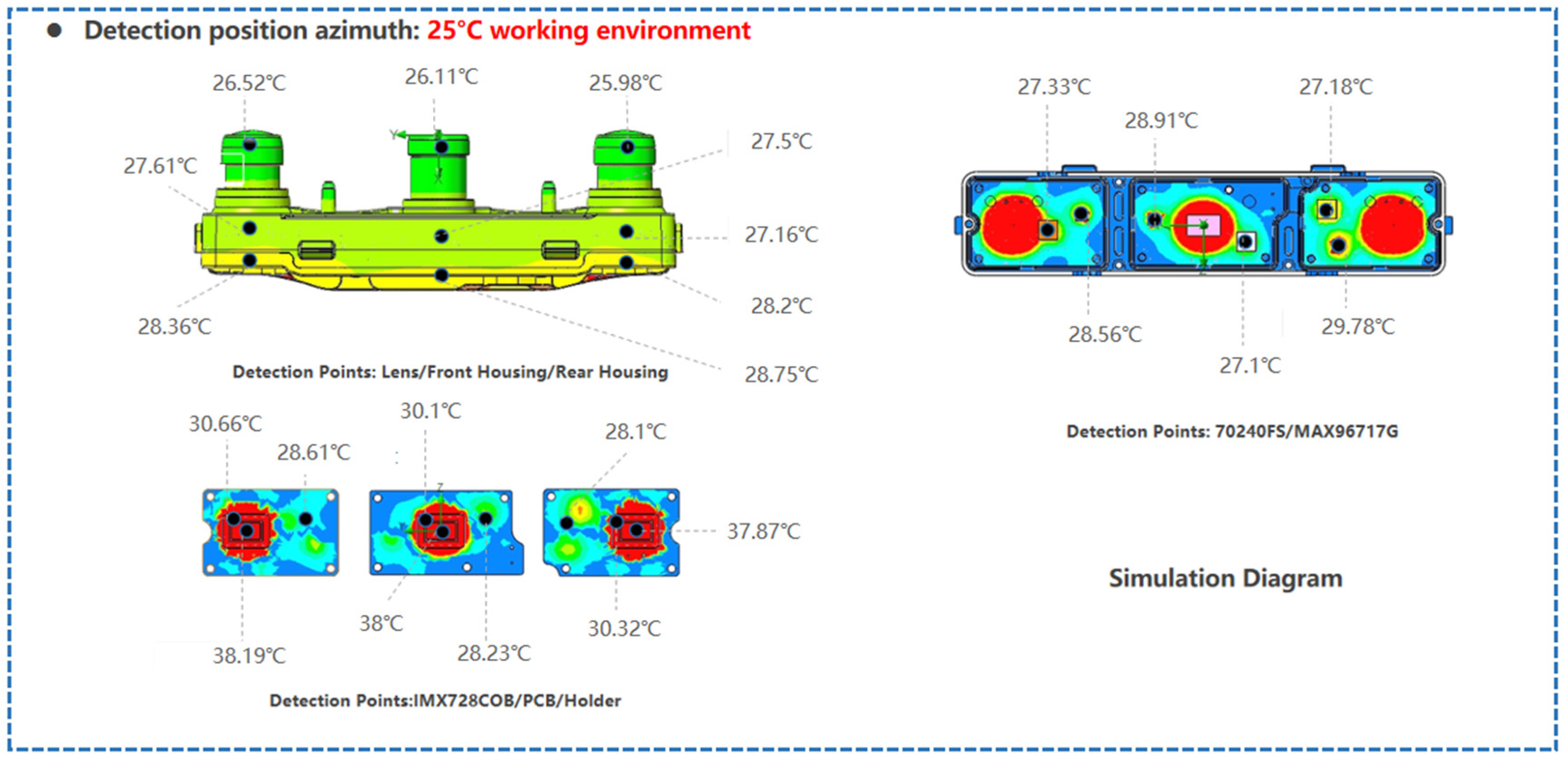
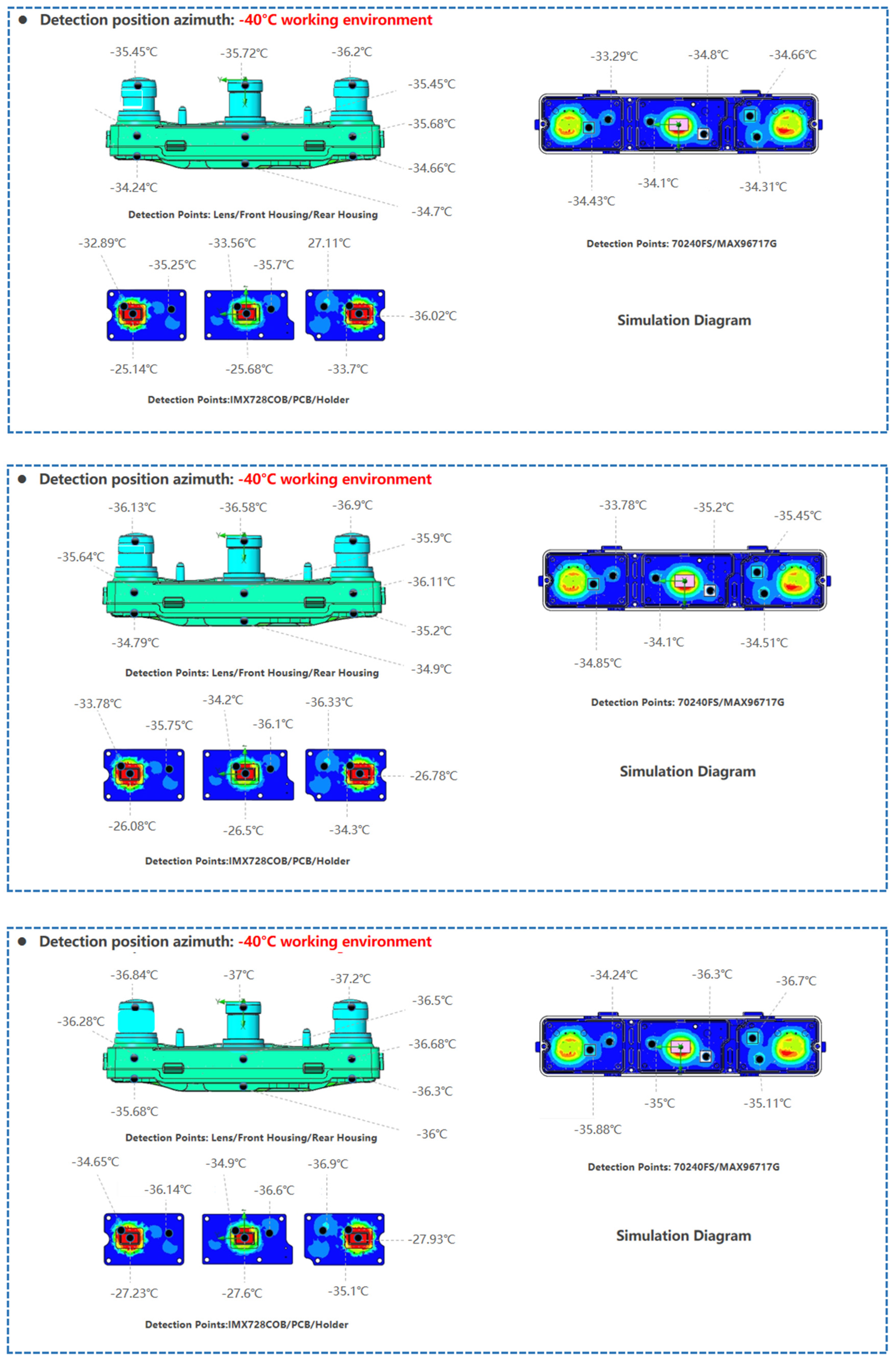
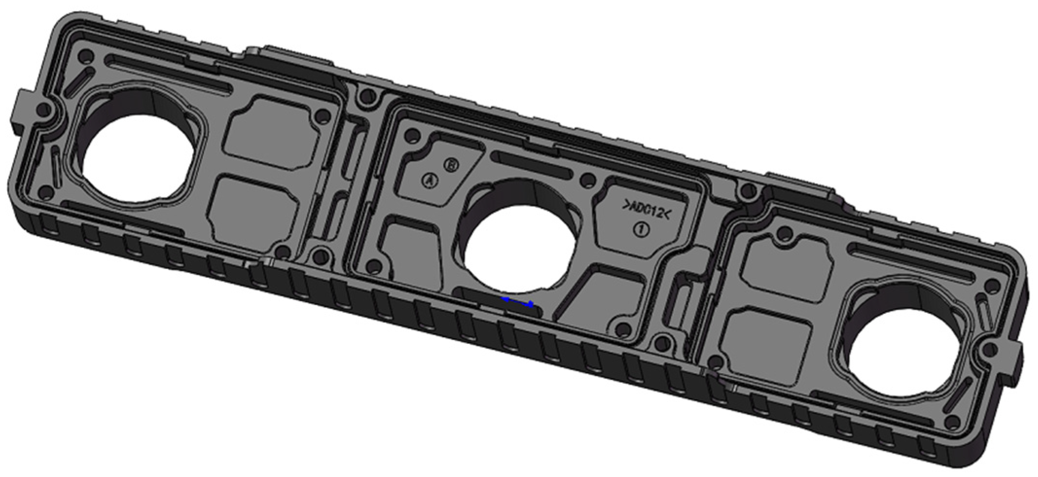
First, different aluminum alloy materials are used to fabricate the camera in order to resist deformation caused by thermal expansion and contraction, thereby reducing the ranging error of the tri-camera and enhancing the stability of stereo vision imaging. The layout of each heat dissipation device is shown in
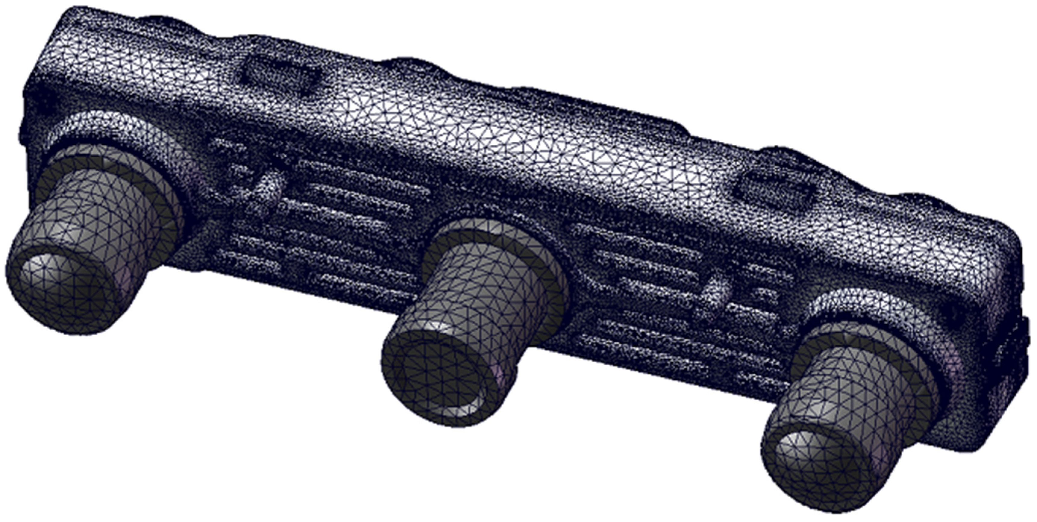
Figure 3. We select three commonly used CNC machining aluminum alloy materials: AL6063-T6, AL6061, and AL7075-T6. The camera mesh model (with 3.63 million elements) is presented in
Figure 4. The temperature distributions under three distinct operating environments are then visualized:
Figure 5 for 95 °C,
Figure 6 for 25 °C, and
Figure 7 for −40 °C. By comparison, the order of material heat dissipation capacity is: AL6063-T6 > AL6061 > AL7075-T6. Due to differences in the heat dissipation capacity of the materials, the temperature values of the corresponding devices are also different. In particular, according to
Table 2,
Table 3 and
Table 4, components fabricated with AL6063-T6 material exhibit better heat dissipation performance, which can reduce the environmental influence on their deformation.
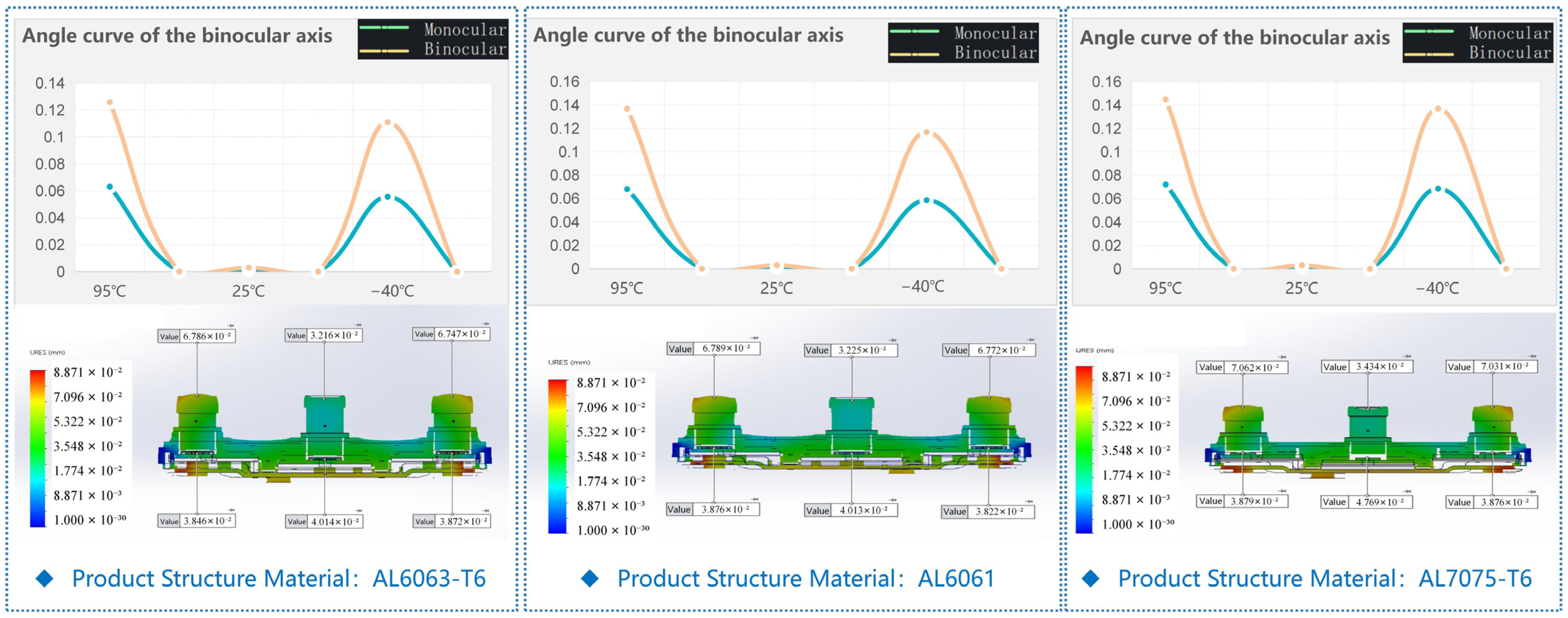
Combined with the above simulation conclusions on thermal properties at different temperatures, the simulated deformation values of the structural parts are obtained, as shown in
Figure 8. In the tri-camera, the offset values of the left and right eye axes follow the material grade order: the product structure material is AL6063-T6 (optical axis offset
δ ≈ 0.134°) < AL6061 (
δ ≈ 0.139°) < AL7075-T6 (
δ ≈ 0.143°). In summary, the AL6063-T6 structural material exhibits the best stability for binocular performance compared with the other two materials.
3.4. Heterogeneous Structure Design
The heterostructure deformation-induced force exists in heterogeneous materials composed of high-strength but low-toughness materials and low-strength but high-toughness materials, and it can resist the deformation of the heterogeneous material. We designed a heterostructure made of AL6063-T6 and AL1060 alloy, as shown in
Figure 9. The properties of AL6063-T6 and AL1060 alloy are shown in
Figure 10. In the heterostructure, the AL6063-T6 region is the hard zone, and the AL1060 alloy region is the soft zone. The deformation-induced force at the interface between the hard and soft zones can resist deformation of the heterostructure [
17].
The finite element analysis results of deformation for the heterostructure material are shown in
Figure 11, with an optical axis offset
δ ≈ 0.133°. Compared with the AL6063-T6 monomer material, the heterostructure exhibits improved deformation resistance, which helps reduce misalignment/measurement error in the tri-camera and enhances stereo vision imaging stability.
3.5. Honeycomb Structure Design
We also apply a honeycomb structure design to the camera to enhance deformation resistance, using AL6063-T6 as the material. A camera with a honeycomb structure is shown in
Figure 12. The appearance surface of the front shell features a honeycomb-like design, and the honeycomb structure design also includes a similar honeycomb pattern for the PCBA contact surface (as long as it meets the functional requirements) and an extended design for the rear shell fins.
We design our tri-camera with stiffening ribs and a honeycomb structure for two main purposes: first, to reduce the overall weight of the metal housing so the tri-camera is not too heavy for installation in vehicles, and to withstand long-term vibration from rough road conditions. This also reduces the pulling force from external mounting hardware once installed on the car. The camera is mounted using a snap-fit (quick-release) connector, which facilitates online installation at the factory (ease of installation) and lowers the risk that external screws, if used to lock the housing, would impose external tensile forces that cause uneven loading on the left and right sides. Such uneven loading could lead to misalignment of the optical axes on both cameras when the temperature is extreme (−40 to 90 °C). Consequently, the optical axes could drift further apart once the vehicle is in service. Additionally, after weight reduction, the stiffening ribs help maintain the strength on both sides, preventing deformation of the middle camera even if the structure is lightly hollowed out.
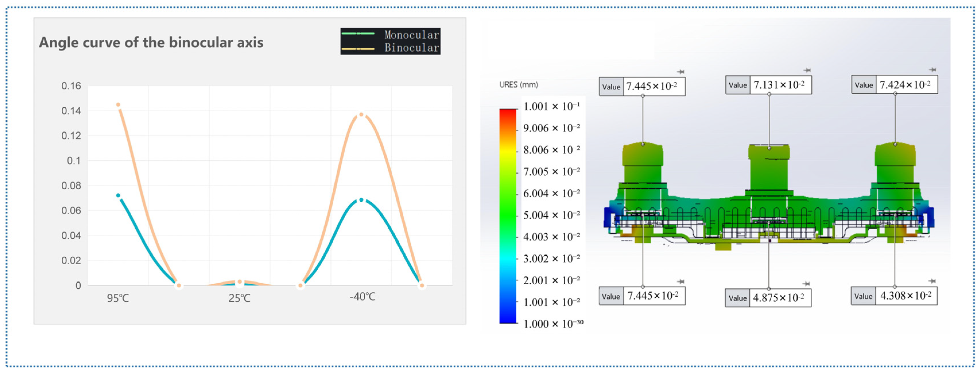
The deformation finite element analysis results for the honeycomb-structured camera are shown in
Figure 13. We derived the thermal performance conclusions at different temperatures by analyzing the simulated deformation values of the structural parts. In the product, this deformation leads to an offset between the left and right optical axes. In the product, the left and right eye axes are offset. Simulation of the honeycomb structure design: the optical axis offset
δ ≈ 0.145°, compared with the AL6063-T6 monomer material, the optical axis offset
δ ≈ 0.134°. The results show that the honeycomb structure design does not enhance the camera’s deformation resistance.
4. Experimental Verification
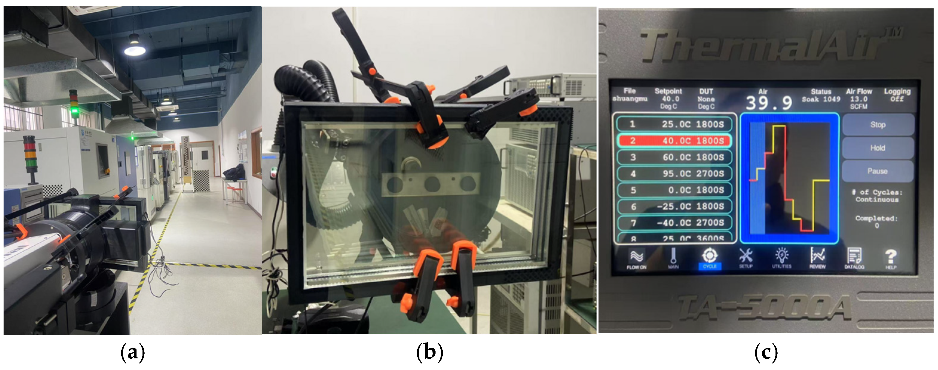
To verify the effectiveness of the finite element analysis for the camera material and structural optimization design, we conducted experimental validation. In particular, the experiments primarily verify the validity of the finite element analysis for the camera material optimization design. The experiments are shown in
Figure 14a, where a tri-camera is placed in a specialized environment (
Figure 14b). The temperature in the environment can be set, and the environment control panel is shown in
Figure 14c.
The experimental results for cameras manufactured with AL6063-T6 are shown in
Table 5. In the range of −40 °C to 95 °C, the maximum pixel deviation is about 2.18 pixels (the pixel size of our camera is 2.1 μm). The maximum angular offset is about 0.067°.
The experimental results for cameras manufactured with AL6061 are shown in
Table 6. In the range of −40 °C to 95 °C, the maximum pixel deviation is about 2.55 pixels. The maximum angular offset is about 0.079°.
The experimental results for cameras manufactured with AL7075-T6 are shown in
Table 7. In the range of −40 °C to 95 °C, the maximum pixel deviation is about 2.55 pixels. The maximum angular offset is about 0.094°.
The experimental results show that AL6063-T6 exhibits the best deformation resistance, which helps reduce camera ranging errors and improve the stability of stereo vision imaging. The experimental results are consistent with the finite element analysis, validating the effectiveness of the finite element analysis for the camera material optimization design.
5. Conclusions
This study investigated material and structural optimization to mitigate environment-induced deformation in tri-camera stereo vision systems for autonomous driving. Key conclusions are drawn as follows:
(1) Material superiority: Among tested aluminum alloys (AL6063-T6, AL6061, AL7075-T6), AL6063-T6 demonstrated optimal stability, minimizing optical axis offset (δ ≈ 0.134°) under extreme temperatures (−40 °C to 95 °C), directly improving imaging robustness.
(2) Heterogeneous structure: The AL6063-T6/AL1060 heterogeneous structure further reduced deformation (δ ≈ 0.133°) by leveraging deformation-induced forces at hard/soft material interfaces, validating its potential for high-precision camera housings. This conclusion is derived from numerical modeling.
(3) Honeycomb limitations: Contrary to expectations, the honeycomb structure design increased optical axis offset (δ ≈ 0.145°), indicating its inadequacy for deformation-sensitive imaging systems. This finding is also based on modeling analysis.
(4) Experimental validation: Field tests confirmed finite element analysis predictions, with AL6063-T6 cameras exhibiting the lowest pixel deviation (max 2.18 pixels) and angular offset (max 0.067°).
These strategies are conducive to improving the stereo ranging accuracy and long-term stability in automotive environments, advancing reliable perception for autonomous systems. Future work will explore topology optimization and multi-material composites for further gains.
