Article

Radar-Only Cooperative Adaptive Cruise Control Under Acceleration Disturbances: ACC, KF-CACC, and Multi-Q IMM-KF CACC

Department of Electrical Engineering, Hanyang University, Seoul 04763, Republic of Korea
*
Author to whom correspondence should be addressed.
Appl. Sci. 2025, 15(22), 12199; https://doi.org/10.3390/app152212199
Submission received: 30 October 2025 / Revised: 14 November 2025 / Accepted: 15 November 2025 / Published: 17 November 2025
(This article belongs to the Special Issue Advances in Autonomous Driving: Detection and Tracking)

Abstract

The rapid increase in global vehicle usage has intensified challenges such as traffic congestion, frequent accidents, and energy consumption, highlighting the need for safe and efficient platooning strategies. Conventional adaptive cruise control (ACC), while widely adopted, suffers from string instability that amplifies disturbances along a platoon. Communication-based cooperative ACC (CACC) can theoretically guarantee string stability at short headways, but its dependence on costly and unreliable vehicle-to-vehicle (V2V) links limits large-scale deployment. Radar-only CACC using single-model Kalman Filter (KF) alleviates this dependency, yet its estimation accuracy degrades under abrupt maneuvers due to model mismatch. To overcome these limitations, this paper proposes a Multi-Q Interacting Multiple Model Kalman Filter (Multi-Q IMM-KF) approach that adaptively blends multiple motion models to ensure robust acceleration estimation across diverse driving conditions. A four-vehicle platoon simulation in CarSim–Simulink demonstrates that the Multi-Q IMM-KF CACC significantly reduces spacing error propagation and improves velocity tracking compared with ACC and Nominal KF-CACC, offering a cost-effective and communication-resilient solution for practical platoon control.

1. Introduction

The rapid growth in global vehicle usage has introduced significant challenges, including traffic congestion, frequent accidents, and increasing energy consumption. Consequently, safety, comfort, and efficiency have become central objectives in the development of intelligent transportation systems. Among various driver-assistance technologies, adaptive cruise control (ACC) has become one of the most widely adopted systems, maintaining inter-vehicle spacing and velocity through onboard radar or LiDAR sensing [1,2,3]. The concept of automated longitudinal control can be traced back to the early PATH program, where coordinated vehicle motion was demonstrated using onboard control and sensing [4].
Despite its commercial success, ACC typically requires large inter-vehicle gaps to ensure safety [5,6], which inherently limits traffic throughput and energy efficiency. In high-density traffic, reducing the time headway can significantly improve road capacity and reduce aerodynamic drag [7,8]. However, at short gaps, ACC is prone to disturbance amplification, where fluctuations in the lead vehicle propagate upstream and cause string instability [9,10]. Moreover, the concept of string stability—formally defined as the attenuation of spacing and velocity errors along the platoon—has been extensively reviewed and mathematically characterized in the literature [11]. Early analytical works also investigated non-communicative platoon control, where stability was achieved solely through onboard sensing without access to lead vehicle information [12]. This phenomenon undermines both traffic safety and passenger comfort, thus restricting the practical deployment of close-gap automation. To overcome these limitations, cooperative adaptive cruise control (CACC) augments ACC by incorporating vehicle-to-vehicle (V2V) communication, allowing each vehicle to access the velocity and acceleration of its predecessors [13,14,15]. This feedforward mechanism enhances disturbance rejection and provides theoretical guarantees of string stability [8,9]. Early implementations using model-based controllers and observer structures demonstrated notable improvements in both stability and fuel economy [16,17]. Experimental validations employing Linear Matrix Inequality (LMI)-based control [18], distributed consensus protocols [19], and Model Predictive Control (MPC) frameworks [20,21] further confirmed the feasibility of cooperative platooning under ideal communication conditions.
However, in practical scenarios, V2V-based architectures face significant challenges such as packet loss, latency, security vulnerabilities, and the high cost of communication infrastructure, which hinder their large-scale adoption [22,23]. To improve robustness and scalability, radar-only CACC structures have been explored as communication-resilient alternatives [1,6,24]. With the rapid advancement of onboard sensing technologies—such as millimeter-wave radar, LiDAR, and inertial measurement units (IMUs)—modern vehicles can estimate relative distance, velocity, and acceleration with high precision. This evolution enables cooperative control through sensor fusion rather than direct communication, maintaining stable platoon behavior even under network loss. Recent studies on proactive autonomous driving and real-time trajectory planning have further extended CACC concepts toward predictive control frameworks that account for surrounding road users [25].
Various observer-based estimators, such as Extended State Observers (ESOs) [26] and Disturbance Observers (DOBs) [27], have been proposed to improve robustness under heterogeneous vehicle dynamics. However, conventional Kalman Filter (KF) approaches with fixed process and measurement noise covariances often fail to adapt to abrupt changes in driving behavior, leading to degraded estimation accuracy under highly dynamic conditions [24].
To address this issue, this paper proposes a Multi-Q Interacting Multiple Model Kalman Filter (Multi-Q IMM-KF) tailored for radar-only CACC systems. The IMM-KF runs multiple Kalman Filters in parallel, each tuned to a specific dynamic regime, and probabilistically fuses their outputs based on mode likelihoods [8]. This design allows smooth transitions between low-jerk cruising and high-jerk maneuvers, thereby improving estimation robustness without relying on inter-vehicle communication [10,14,15]. Furthermore, the proposed Multi-Q structure adaptively adjusts process noise covariances to enhance both estimation accuracy and real-time performance in embedded vehicle platforms.
The main contributions of this paper are summarized as follows:
  • A unified modeling and evaluation framework for ACC, KF-CACC, and Multi-Q IMM-KF-CACC under a constant time gap (CTG) policy.
  • A detailed design methodology for the Multi-Q IMM-KF estimator, leveraging multi-model blending to accommodate diverse driving dynamics [24].
  • A comprehensive performance comparison demonstrating improved spacing error attenuation and velocity tracking accuracy without relying on V2V communication [8,27].

2. System Modeling

This section presents the longitudinal vehicle dynamics and control modeling framework for adaptive cruise control (ACC) and cooperative adaptive cruise control (CACC) systems. For clarity, the overall platoon structure considered in this study is shown in Figure 1. Since these formulations are well established in the prior CACC literature [6,8], only the essential equations are summarized for clarity. The continuous-time model is derived under the constant time-gap (CTG) policy and subsequently discretized for digital implementation, providing the foundation for the control and estimation designs.

2.1. Longitudinal Vehicle Dynamics

The longitudinal acceleration dynamics of each vehicle are modeled as a first-order lag system to represent actuator delay:
a i ( s ) = 1 τ i s + 1 u i ( s ) ,
where s denotes the Laplace operator, u i ( s ) is the commanded acceleration, and τ i is the actuation time constant of the ith vehicle. In the time domain,
x ˙ i = v i , v ˙ i = a i , a ˙ i = 1 τ i a i + 1 τ i u i .
This compact model captures the essential longitudinal behavior of the powertrain and forms the basis for motion control.

2.2. Discretization

For digital implementation, the continuous-time model is discretized using a zero-order hold (ZOH) method with sampling period T s :
a i ( k + 1 ) = α i a i ( k ) + β i u i ( k ) ,
where α i = e T s / τ i and β i = 1 α i . This discrete-time representation has been widely used in longitudinal control and estimation studies [14], and thus only the key relationships are presented here for completeness.

2.3. Constant Time-Gap (CTG) Spacing Policy

To ensure safe and stable following, the CTG spacing policy defines the desired inter-vehicle distance as
δ i , des ( k ) = r i + h v i ( k ) ,
where r i and h denote the standstill distance and headway time, respectively. The actual spacing and corresponding error are
δ i ( k ) = x i 1 ( k ) x i ( k ) l i , e i ( k ) = δ i ( k ) δ i , des ( k ) .
This policy linearly couples velocity and spacing through h, ensuring string stability as demonstrated in previous ACC/CACC research [9,10,28].

2.4. Adaptive Cruise Control (ACC) Dynamics

Based on the CTG policy and the discretized longitudinal dynamics, the state–space representation of the ACC system is derived. The state vector of the ith vehicle is defined as
x i ( k ) = e i ( k ) v i ( k ) a i ( k ) T ,
where e i ( k ) is the spacing error, v i ( k ) the ego velocity, and a i ( k ) the actual acceleration.
From the vehicle dynamics in (3)–(5) and the spacing policy in (8), the discrete-time state–space model is obtained as
x i ( k + 1 ) = 1 T s h T s 0 1 T s 0 0 α i A d , i x i ( k ) + 0 0 β i B d , i u i ( k ) + T s 0 0 B v v i 1 ( k ) .
The matrix A d , i captures the coupling between velocity and spacing error through the term h T s , while B v represents the effect of the preceding vehicle’s velocity. This structure reflects the interactive nature of platooning in ACC systems.

2.5. Cooperative Adaptive Cruise Control (CACC)

While ACC regulates spacing using only onboard sensing, it remains vulnerable to disturbance propagation from the preceding vehicle, leading to spacing oscillations and degraded ride comfort. In contrast, CACC incorporates additional information—typically the velocity and acceleration of the preceding vehicle—to enhance tracking performance and achieve string stability across the platoon [9,13,14]. Early studies have also shown that even in the absence of communication, limited cooperation through observer-based estimation can achieve partial string stability [12].
Conventional CACC implementations employ V2V communication for information exchange. In this study, however, a radar-only architecture is utilized, where the lead vehicle’s acceleration is estimated using onboard sensors such as radar and inertial measurement units (IMUs). This approach enables cooperative behavior without explicit communication, improving practicality and robustness under real-world conditions [1,24].
Recent research has extended the CACC framework to address stability, safety, and efficiency under more realistic and diverse conditions. For instance, Dai et al. analyzed the stability and rear-end collision risk of CACC platoons under various information flow topologies, showing that multi-predecessor information improves stability but may influence safety margins [29]. Lee et al. proposed a PD control scheme with feedforward compensation that ensures both individual vehicle stability and string stability in homogeneous platoons, providing frequency-domain design guidelines for gain tuning [30]. Furthermore, Dong et al. investigated mixed-traffic platoons consisting of connected and human-driven vehicles, revealing that optimal spatial formation significantly affects energy and traffic efficiencies [31]. These recent works emphasize the importance of considering control topology, inter-vehicle communication, and platoon formation when evaluating the cooperative performance of ACC/CACC systems.
The control input u i ( k ) represents the commanded acceleration, composed of feedback and feedforward components:
u i ( k ) = u i fb ( k ) + u i ff ( k ) .
The feedback term stabilizes the local spacing error and compensates for internal uncertainties. It is implemented as a discrete-time proportional–derivative (PD) controller based on the CTG policy:
u i fb ( k ) = k p e i ( k ) + k d e i ( k ) e i ( k 1 ) T s ,
where k p and k d denote the proportional and derivative gains, respectively. This structure ensures local asymptotic convergence of e i ( k ) to zero [6].
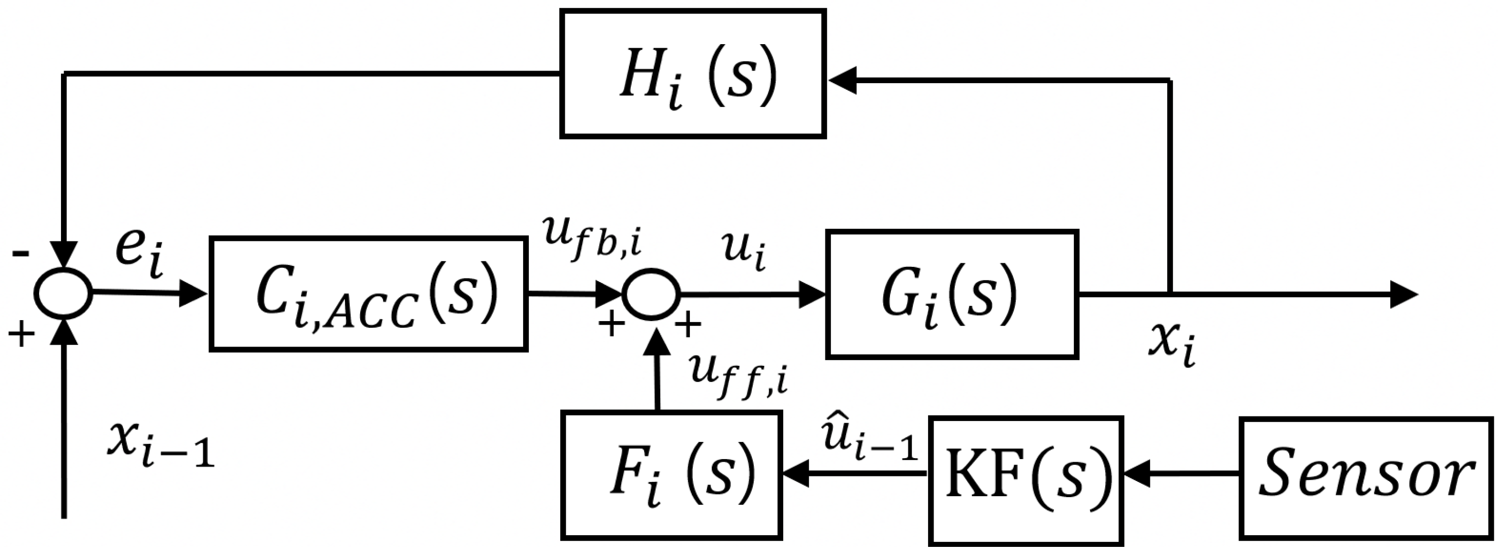
To further improve disturbance rejection and maintain string stability, a feedforward filter is introduced to anticipate the influence of the preceding vehicle’s motion. Following the standard CACC formulation [8,9,30], the feedforward filter is defined in the continuous-time domain as
F i ( s ) = H ( s ) G i ( s ) s 2 1 , H ( s ) = h s + 1 , G i ( s ) = 1 ( τ i s + 1 ) s 2 ,
where h denotes the time headway and τ i represents the actuation delay of the ith vehicle.
The filter F i ( s ) is discretized using the zero-order hold (ZOH) method to obtain F i ( z ) , resulting in the discrete control law:
u i ( k ) = u i fb ( k ) + F i ( z ) a i 1 ( k ) ,
where the feedforward term is expressed as
u i ff ( k ) = F i ( z ) a i 1 ( k ) .
Incorporating the feedforward component yields the closed-loop CACC dynamics:
x i ( k + 1 ) = A d , i cl x i ( k ) + B d , i cl v i 1 ( k ) + 0 0 β i B ff u i ff ( k ) ,
where A d , i cl and B d , i cl denote the closed-loop state–space matrices under the PD-plus-feedforward control structure.
Since the preceding vehicle’s acceleration a i 1 ( k ) is not directly measurable in the radar-only configuration, it is estimated in real time using a Kalman Filter, as detailed in the following section.

3. Kalman Filter Design

3.1. Requirement for Kalman Filtering in Radar-Only CACC

In the proposed radar-only CACC architecture, the feedforward controller requires the lead vehicle’s acceleration a i 1 ( k ) , which cannot be directly measured without V2V communication. To preserve cooperative behavior in the absence of such communication, the acceleration is estimated using a discrete-time Kalman Filter (KF) based on the relative motion model introduced in Section 2.4. This model, constructed from the longitudinal dynamics and constant time-gap (CTG) policy, provides the baseline structure for the estimator. The following subsections summarize the Nominal KF formulation and discuss its limitations under dynamic driving conditions.

3.2. Nominal KF-Based Estimation

The KF formulation follows a standard discrete-time structure defined based on the relative kinematic state x k rel = [ d rel ( k ) , v rel ( k ) , a rel ( k ) ] T , where d rel , v rel , and a rel represent the relative distance, velocity, and acceleration between the ego and lead vehicles, respectively. Based on the CTG-based longitudinal model of Section 2.3, the discrete-time dynamics are represented as
x k + 1 = A x k + B u k ,
y k = C x k ,
with the state and measurement matrices
A = 1 T s 0.5 T s 2 0 1 T s 0 0 1 , B = 0.5 T s 2 T s 0 , C = 1 0 0 0 1 0 .
Here, x k denotes the relative state, u k is the ego vehicle’s commanded acceleration (known input), and y k contains the measured relative distance and velocity.
This baseline KF estimates the lead vehicle’s acceleration from onboard radar and IMU data. However, its accuracy degrades under abrupt acceleration changes because the fixed process noise assumption cannot capture rapid dynamic transitions. To address this limitation, a multi-model estimation framework is introduced in the following subsection.

3.3. Multi-Q IMM-KF-Based Estimation

Accurate estimation of the predecessor’s acceleration is crucial in feedforward-based CACC systems since the feedforward input directly depends on this variable. Any delay or bias in estimation propagates through the control loop, leading to amplified spacing errors and degraded platoon stability [8]. While a conventional KF with fixed process noise performs adequately under steady conditions, it fails to adapt to sudden braking or merging, where noise statistics vary rapidly.
The overall architecture of the proposed Multi-Q IMM-KF-based CACC system is illustrated in Figure 2.
To address this, a Multi-Q Interacting Multiple Model Kalman Filter (IMM-KF) is adopted. Unlike the single-model KF, which assumes stationary noise, the IMM-KF maintains multiple KFs in parallel, with each being tuned to a distinct driving regime via different process noise covariances. The final estimate is obtained as a probabilistic combination of the individual model outputs based on their likelihoods given the current measurements, enabling smooth adaptation between steady and dynamic maneuvers.

3.3.1. Modeling Philosophy

The proposed IMM-KF utilizes two dynamic modes, detailed as follows.
  • Low-jerk (LJ) mode: This mode employs a small process noise covariance Q LJ for steady cruising.
  • High-jerk (HJ) mode: This mode uses a large covariance Q HJ for rapid responsiveness during aggressive maneuvers.
Both models share identical state–space matrices ( A , B , C ) derived from the constant-acceleration model, ensuring consistent physical interpretation [6,24].

3.3.2. Step 1: Mixing

At each time step, prior estimates from all modes are combined into a mixed initial condition using mode transition probabilities p i j :
μ i | j k 1 = p i j μ i k 1 m p m j μ m k 1 , x ^ 0 , j k 1 = i μ i | j k 1 x ^ i k 1 .

3.3.3. Step 2: Mode-Matched Filtering

Each mode j { 1 , 2 } executes a KF with its specific process noise Q j :
x ^ j k | k 1 = A x ^ j k 1 + B u k 1 , P j k | k 1 = A P j k 1 A + Q j .
The LJ model prioritizes noise suppression, whereas the HJ model enhances responsiveness.

3.3.4. Step 3: Mode Probability Update

Each mode’s likelihood is evaluated using the measurement innovation:
Λ j k = 1 2 π | S j k | exp 1 2 ( y k C x ^ j k ) ( S j k ) 1 ( y k C x ^ j k ) .
Mode probabilities are then updated as
μ j k = Λ j k i p i j μ i k 1 m Λ m k i p i m μ i k 1 .

3.3.5. Step 4: Estimate Fusion

Finally, the IMM output is obtained by fusing the individual mode estimates:
x ^ k = j μ j k x ^ j k , P k = j μ j k P j k + ( x ^ j k x ^ k ) ( x ^ j k x ^ k ) .
The resulting estimate x ^ k includes the predicted lead vehicle acceleration a i 1 ( k ) , which is subsequently used in the feedforward control law of the radar-only CACC system. The overall control structure of the radar-only CACC system is illustrated in Figure 3.

4. String Stability Analysis

String stability is a fundamental requirement in vehicle platooning, ensuring that disturbances generated by the lead vehicle do not grow as they propagate downstream [9,10]. Classical definitions are typically expressed in the frequency domain as
G X ( j ω ) 1 , ω ,
where G X ( j ω ) is the transfer function relating the lead–follower spacing errors.
However, this formulation assumes a linear time-invariant (LTI) system with an analytically tractable transfer representation. The radar-only CACC structure proposed in this study incorporates the IMM-KF estimator, which introduces nonlinear mode transitions, stochastic noise effects, and sensor-induced uncertainties. These characteristics make the derivation of an accurate transfer function impractical, and the frequency-domain criterion cannot faithfully reflect the system dynamics.
Given these practical constraints, we adopt a time-domain notion of practical string stability, which evaluates whether spacing and velocity disturbances remain bounded and do not exhibit unrestrained amplification:
| e i ( k ) | | e i 1 ( k ) | + ε , i > 1 ,
where ε represents a small allowable tolerance arising from sensing and estimation uncertainty.
This formulation is more suitable for radar-only CACC systems, where perfect attenuation ( ε = 0 ) is not achievable in practice but maintaining bounded and non-divergent spacing errors is essential for safe platoon operation.
To complement the time-domain analysis, a quantitative RMSE-based evaluation was also conducted using velocity tracking errors along the platoon. Although the RMSE of downstream vehicles increases slightly due to the absence of V2V communication, the growth remains limited (typically less than 1 m/s), demonstrating that disturbances do not diverge. In particular, the proposed IMM-KF-CACC exhibits smaller RMSE growth compared with the Nominal KF-CACC baseline, confirming its enhanced robustness to disturbance propagation.
Overall, the combined evidence from spacing error trajectories and RMSE-based quantitative analysis verifies that the proposed method achieves practical string stability, suppressing error amplification and maintaining bounded inter-vehicle behavior under realistic sensing and communication constraints.

5. Simulation Setup and Results

The proposed Multi-Q IMM-KF was validated through CarSim–Simulink co-simulation using a four-vehicle platoon (one leader, four followers). All vehicles shared an actuation lag of τ = 0.3 s and followed the CTG policy ( h = 0.5 s) with a sampling period of T s = 0.01 s. The leader trajectory consisted of three phases: (1) mild acceleration/deceleration; (2) aggressive maneuvers with sharp acceleration and braking; (3) steady cruising. This setup allowed both smooth and abrupt dynamics to be evaluated.
The IMM mode transition probabilities were defined as follows:
P = 0.9 0.1 0.1 0.9 .
These probabilities correspond to ε = 0.1 , which provides a balanced trade-off between mode persistence and responsiveness. Additionally, simulations were conducted with ε = 0.05 and ε = 0.2 , representing lower and higher switching sensitivities, respectively. The results exhibited consistently stable and convergent behavior across these values, indicating that the overall estimation and control performance is robust to large-step variations in ε .

5.1. ACC vs. Nominal KF vs. Multi-Q IMM-KF

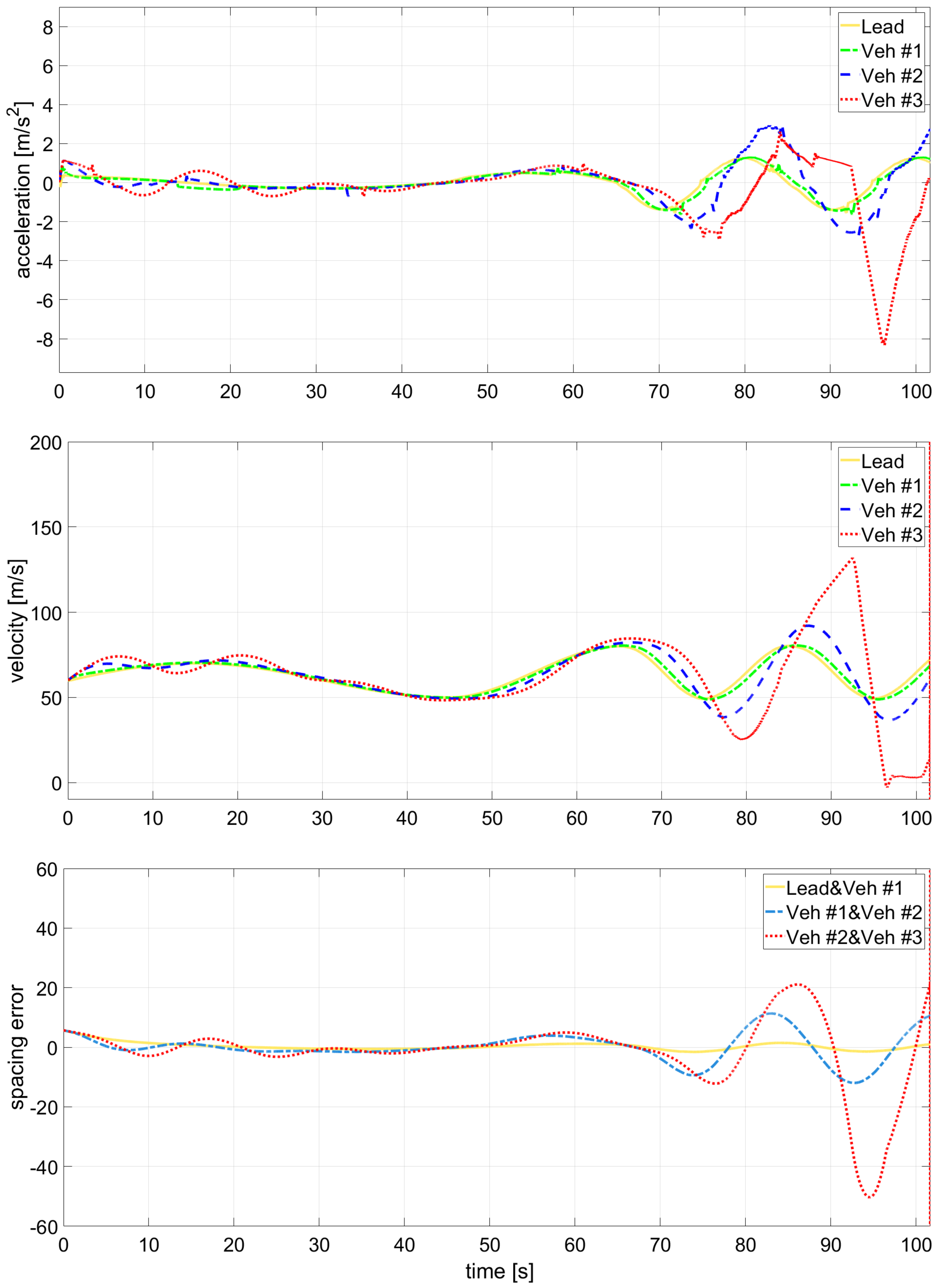
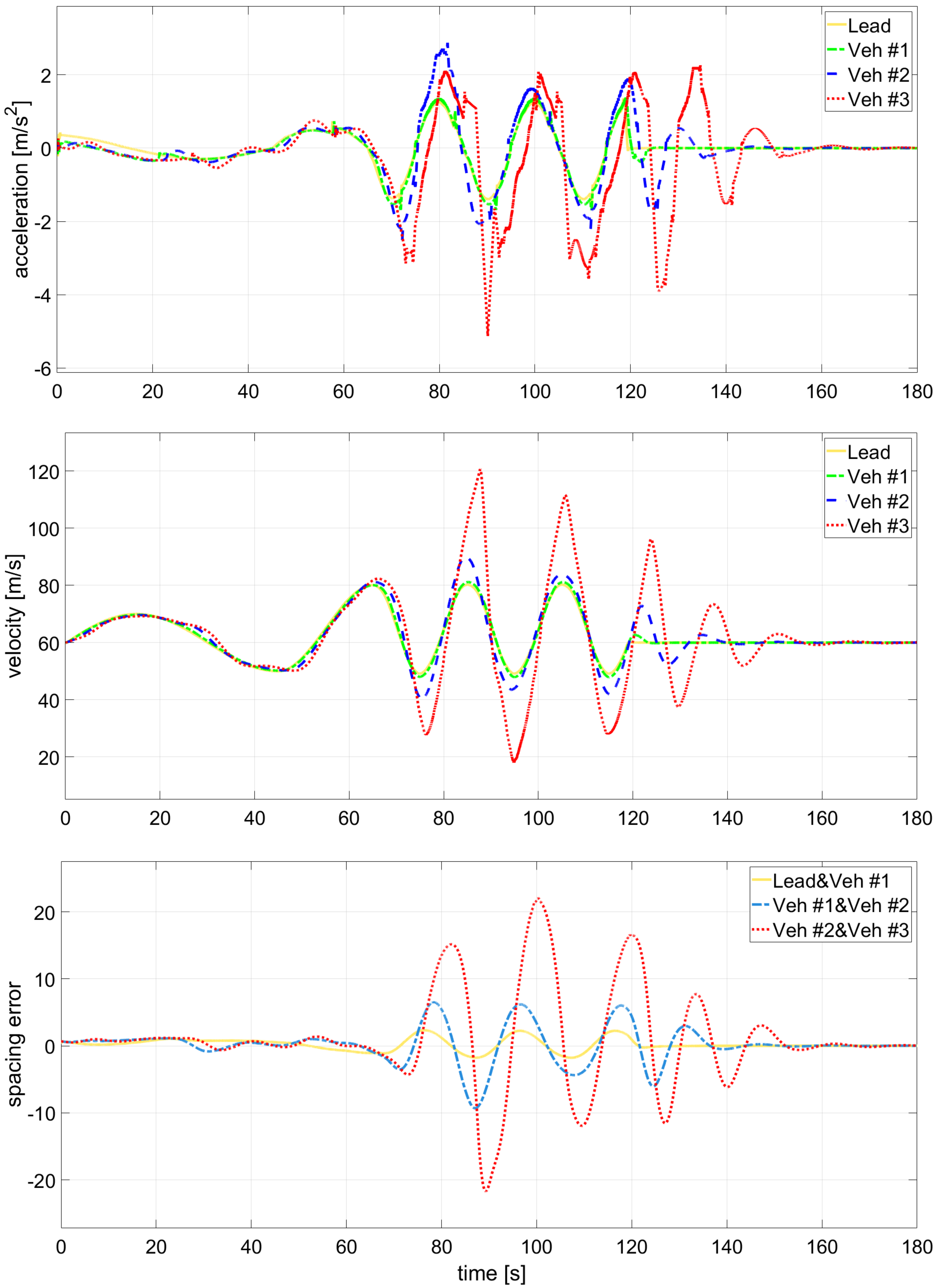
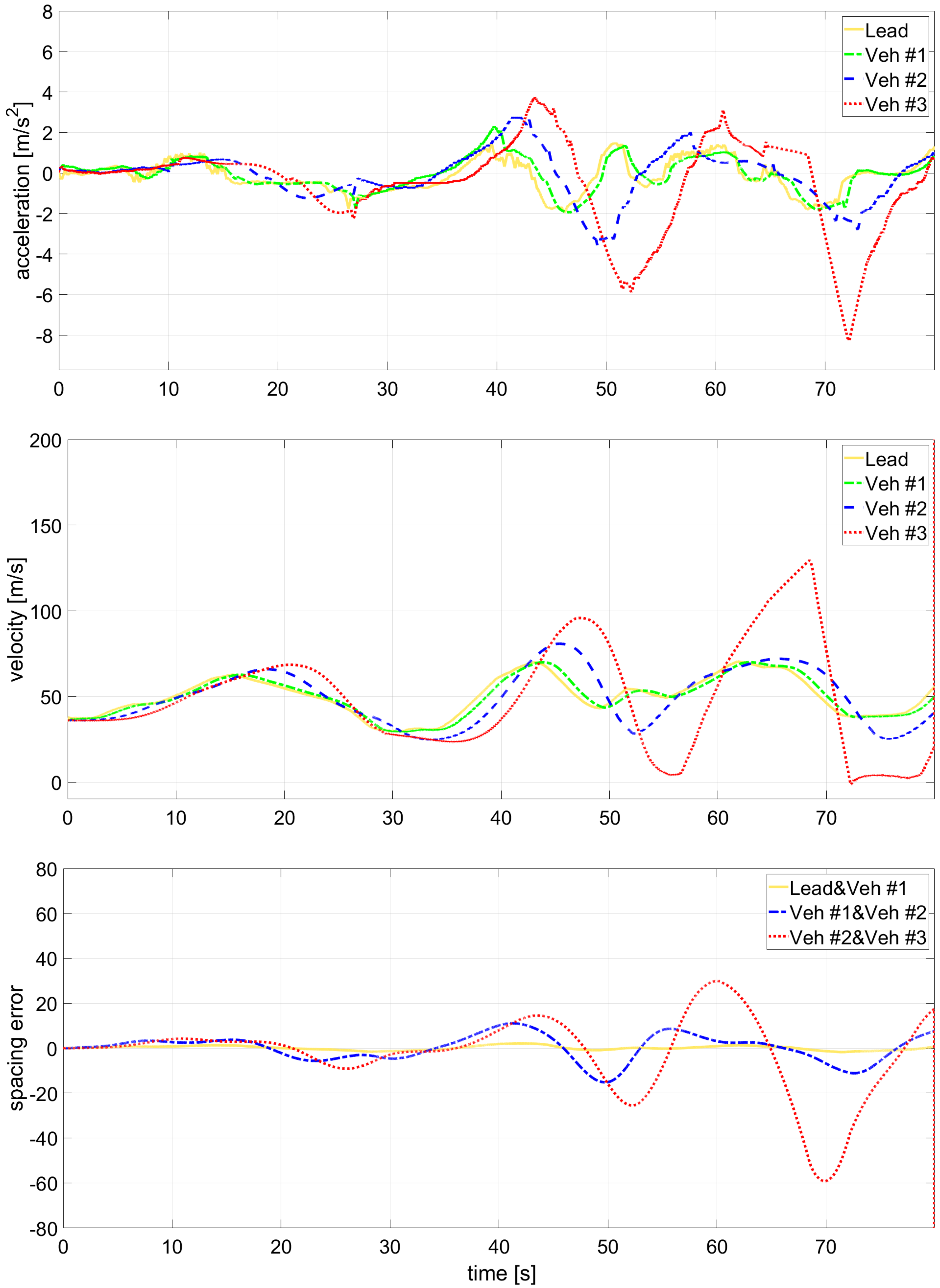
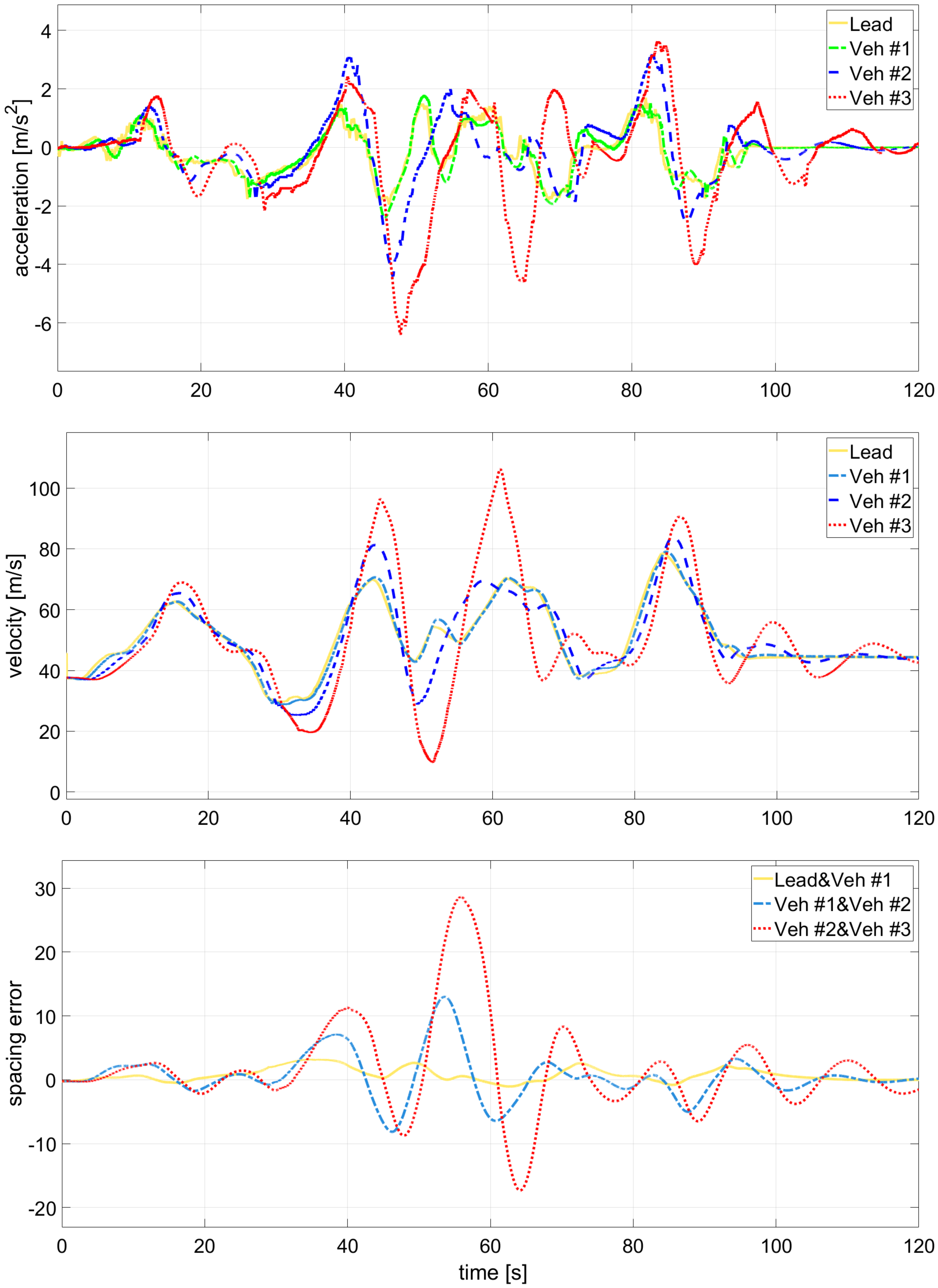
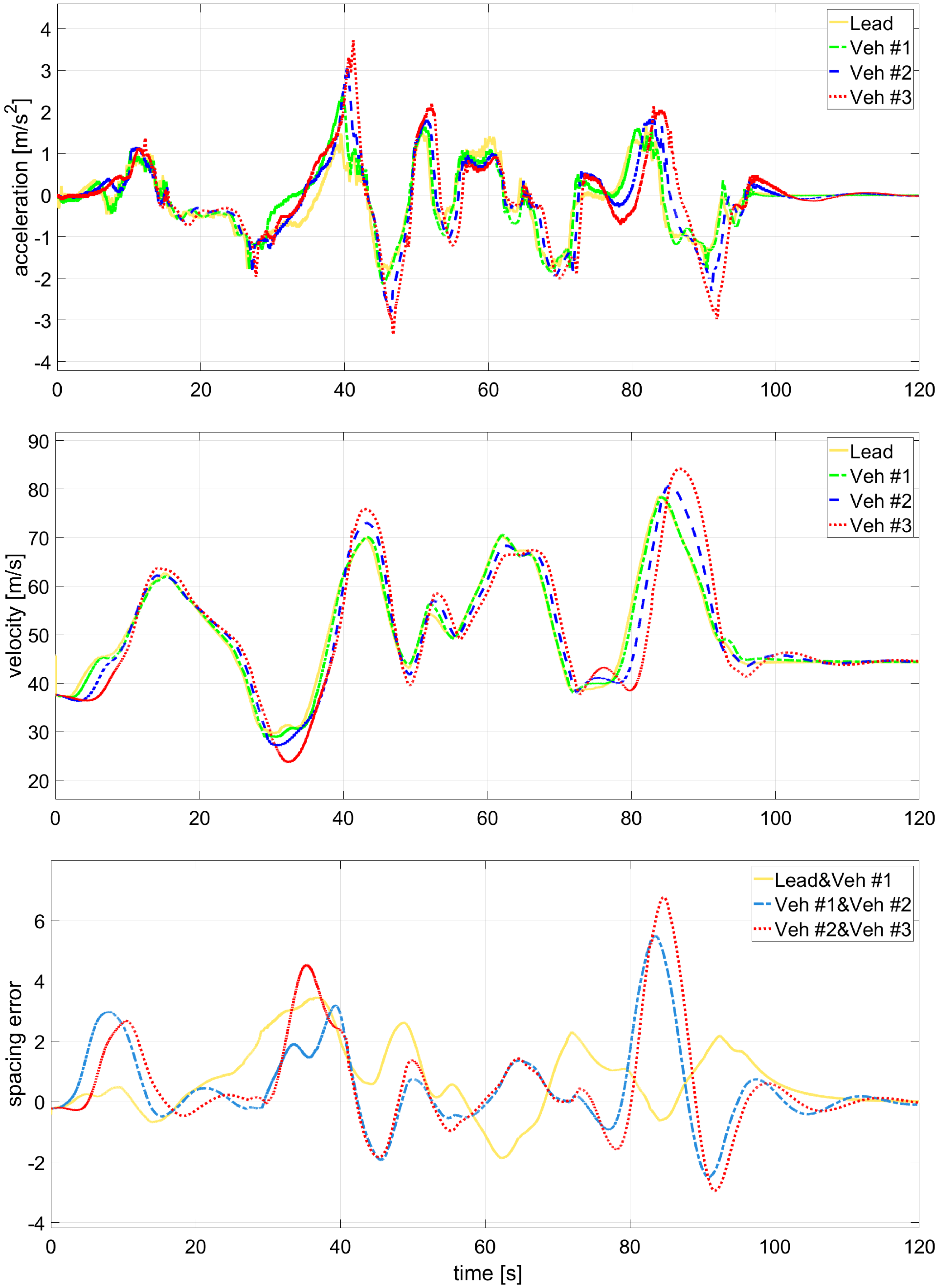
As shown in Figure 4, Figure 5 and Figure 6, conventional ACC, Nominal KF-CACC, and Multi-Q IMM-KF-CACC were experimentally compared under identical headway and acceleration disturbance conditions. During smooth cruising phases, all three controllers maintained stable spacing, with vehicle velocities and accelerations remaining well aligned with the leader. However, the performance difference became evident in the high-jerk interval between 60 s and 120 s, where the lead vehicle performed rapid acceleration and deceleration maneuvers.
In Figure 4, the conventional ACC—operating with a short headway time—exhibited divergence in both velocity and spacing responses. The spacing error oscillations grew significantly when the lead vehicle underwent sharp acceleration or braking, showing the system’s sensitivity to high-frequency disturbances.
As shown in Figure 4, the conventional ACC exhibited noticeable divergence in both velocity tracking and spacing error during high-jerk maneuvers. This instability arose from the controller’s inability to compensate for unmodeled dynamics under nonlinear conditions.
Figure 5 demonstrates that the Nominal KF-CACC improved overall stability compared with the baseline ACC by effectively suppressing spacing oscillations. However, small overshoots and delayed responses remain visible in the acceleration tracking curves, particularly near transition points, because the single-model KF cannot fully capture abrupt dynamic variations.
In contrast, Figure 6 highlights the superior performance of the proposed Multi-Q IMM-KF-CACC. Both velocity and acceleration trajectories remain smooth and closely follow the leader throughout all intervals, while the spacing error stays tightly bounded even during high-jerk phases. This confirms that the IMM-based adaptive mode switching effectively handles dynamic transitions, reducing overshoot and steady-state bias. Consequently, the proposed controller achieves consistent tracking performance and robust disturbance rejection, ensuring enhanced ride comfort and platoon stability even under aggressive and low-headway conditions.
To complement the trajectory-based observations, the velocity tracking RMSE results in Table 1 provide a quantitative comparison of the disturbance propagation characteristics. While the Nominal KF-CACC exhibits moderate improvement over the baseline ACC, the RMSE increases noticeably for downstream vehicles due to limited adaptability. In contrast, the proposed Multi-Q IMM-KF-CACC consistently achieves lower RMSE across all follower vehicles, with the most significant reduction observed in the fourth vehicle. These results confirm that the multi-model structure effectively suppresses error amplification and enhances robustness against abrupt dynamic variations, thereby improving overall platoon stability.

5.2. IMM Mode Probabilities

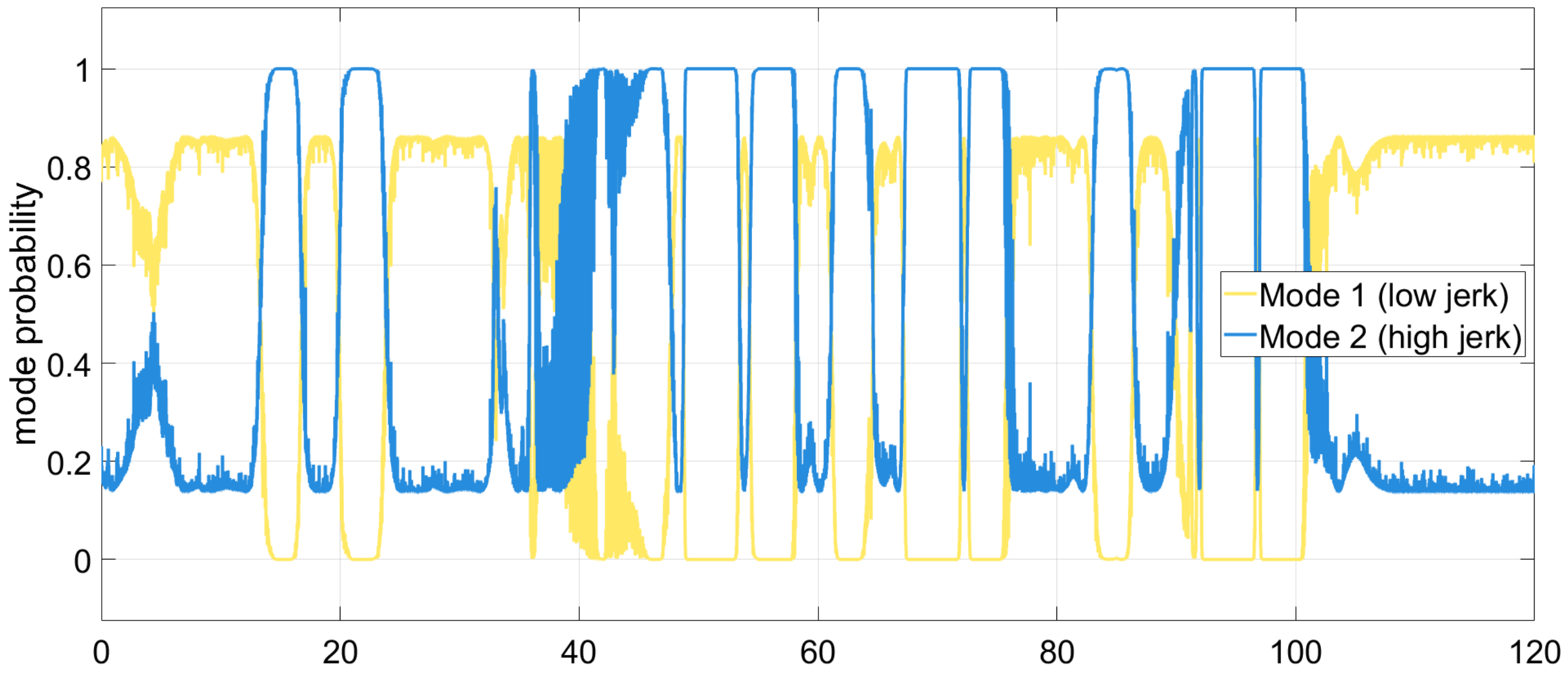
As depicted in Figure 7, the Multi-Q IMM-KF adaptively transitions between the low- and high-jerk models depending on the driving condition. During aggressive acceleration and braking, the probability of the high-jerk mode rises close to unity, indicating that the estimator promptly adapts to sudden dynamics. Conversely, the low-jerk mode dominates during smooth cruising, ensuring stable estimation accuracy.
In the intermediate interval ( T = 60 –120 s), small fluctuations appear between the two modes as vehicle acceleration approaches zero, leading to ambiguous likelihood evaluations during IMM updates. This switching does not imply estimator instability but rather reflects the inherent stochastic nature of the IMM when system excitation is minimal. Because the IMM operates probabilistically, such local oscillations do not propagate through the control loop and thus have negligible influence on overall platoon stability.

6. Experimental Validation Using Real Vehicle Data

6.1. Experimental Setup

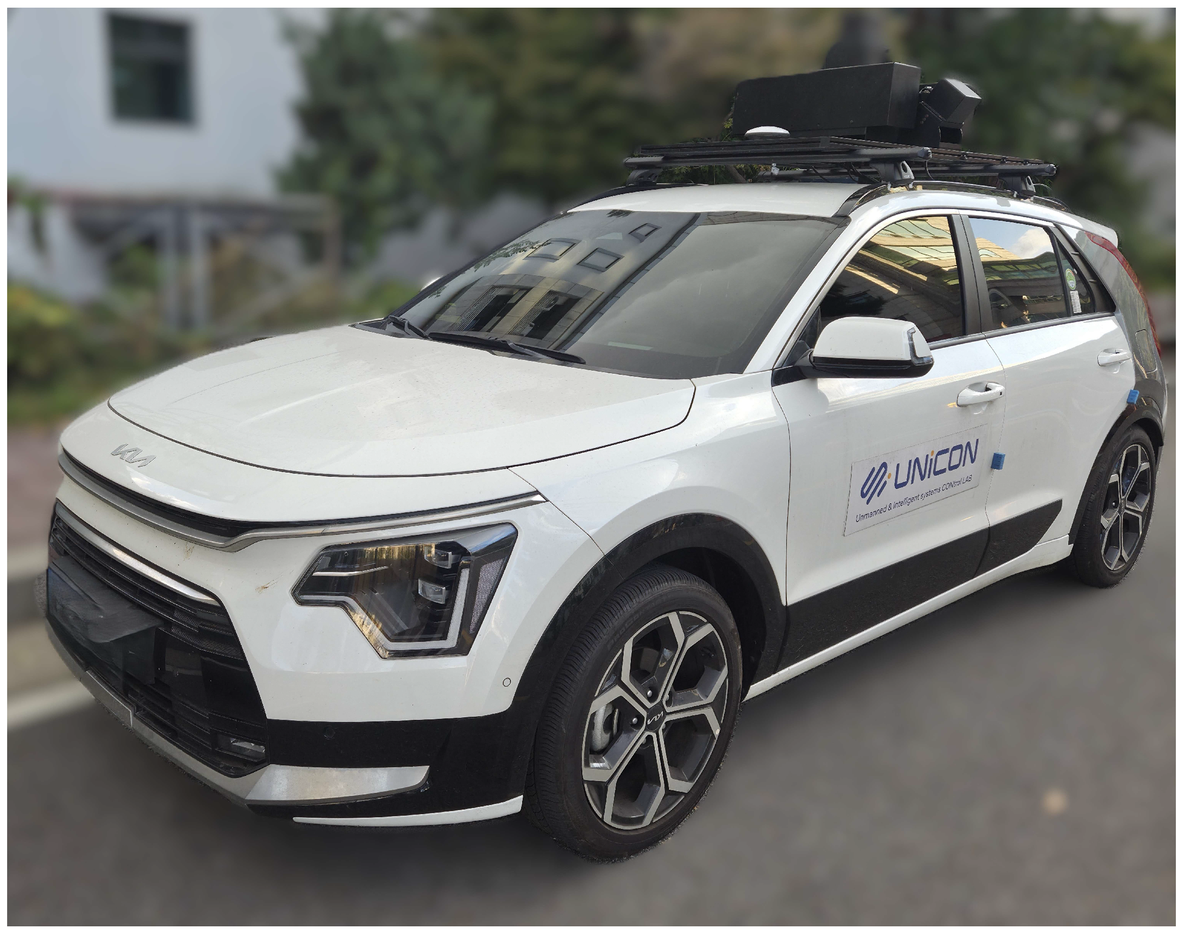
To validate the real-world performance of the proposed Multi-Q IMM-KF-CACC architecture, a field experiment was conducted at the C-Track autonomous driving testbed of Chungbuk National University, Cheongju, South Korea. The experimental platform was a compact SUV (Kia Niro Hybrid; Kia Corp., Seoul, Republic of Korea) equipped with a VectorNav VN-1640 GPS/IMU module (VectorNav Technologies, Dallas, TX, USA) and built-in CAN-based velocity sensors. The data were collected through an onboard logging system implemented on an HP laptop PC. Simulation analysis was performed using CarSim 2023.1 and MATLAB/Simulink R2024b.
Experimental parameters were configured to match the simulation setup, with the actuation lag τ = 0.3 s , headway time h = 0.5 s , and sampling period T s = 0.01 s . Unlike the segmented trajectories used in simulation, the real-vehicle test followed a continuous driving route with repeated acceleration and deceleration events, including curved-road segments.
The IMM estimator employed two motion models—low-jerk (LJ) and high-jerk (HJ)— with the mode transition probability matrix
P = 0.9 0.1 0.1 0.9 .
These probabilities allow sufficient mode persistence while enabling rapid adaptation to dynamic maneuvers such as merging or emergency braking.
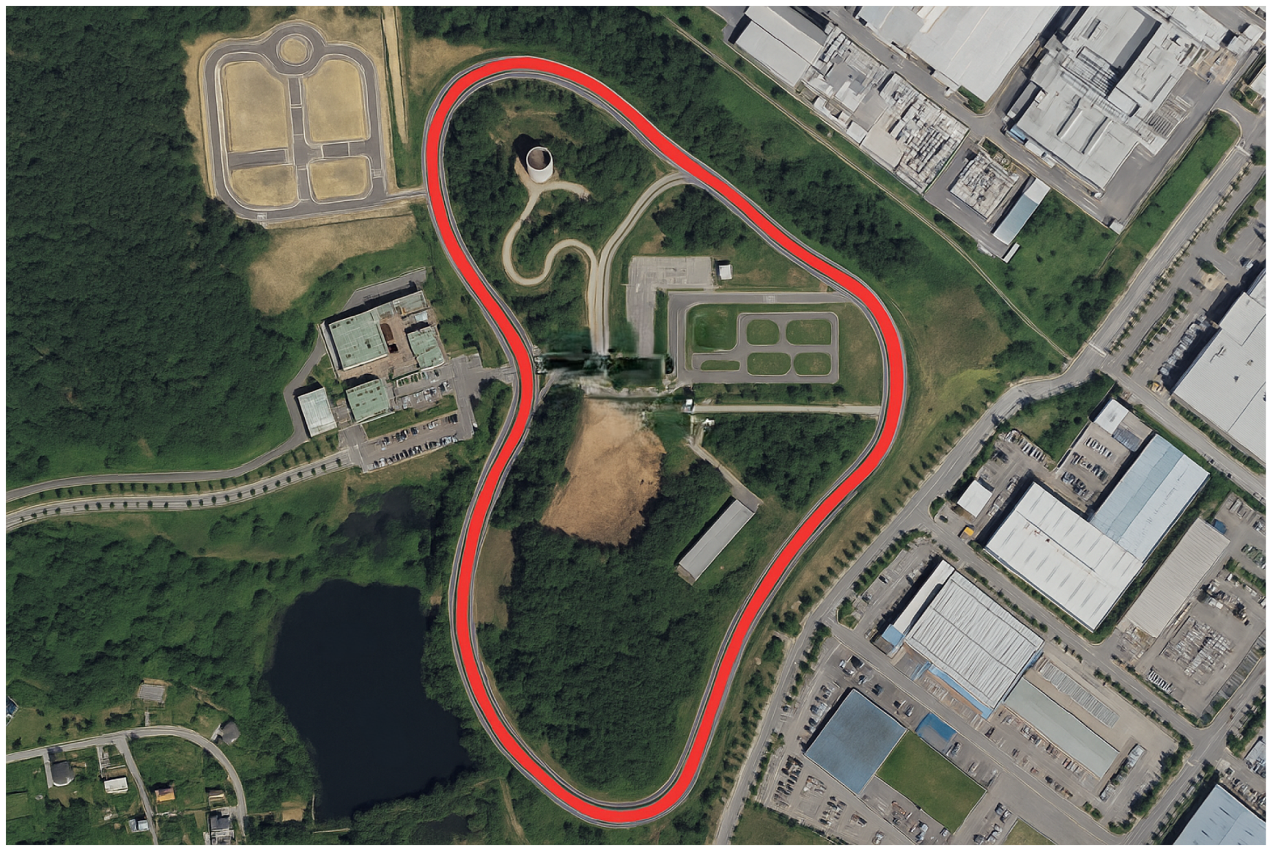
Figure 8 shows the experimental vehicle, and Figure 9 illustrates the driving route used in the field experiment, where the red line indicates the actual path taken during the test. experiment on the C-Track testbed.

6.2. Comparative Results and Discussion

As shown in Figure 10, Figure 11 and Figure 12, clear performance distinctions are observed among the three control architectures. In Figure 10, the conventional ACC exhibits divergence in both velocity tracking and spacing error during high-jerk maneuvers, particularly when the lead vehicle experiences rapid acceleration and braking. The pronounced oscillations in the spacing error reveal the controller’s sensitivity to nonlinear dynamics and short-headway operation, as it relies solely on relative distance feedback.
Figure 11 shows that the Nominal KF-CACC significantly enhances stability compared with conventional ACC by reducing spacing oscillations and improving transient response. However, small overshoot and phase delays are still observed in acceleration estimation, especially during rapid transitions, indicating limited adaptability of the fixed-noise model under dynamic conditions.
In contrast, Figure 12 clearly demonstrates the superior consistency and robustness of the proposed Multi-Q IMM-KF-CACC. The velocity and acceleration tracking trajectories remain smooth and closely follow the lead vehicle across all intervals, while spacing error remains tightly bounded even under high-jerk and curved road conditions. This stability verifies that the adaptive mode-switching mechanism effectively accommodates both transient and steady-state behaviors, maintaining robustness against sensor noise and modeling uncertainties. Moreover, the IMM-based estimator achieves faster convergence following abrupt acceleration changes, reducing estimation delay and improving controller responsiveness. The resulting smooth spacing response leads to lower control effort and enhanced passenger comfort, further reinforcing the overall platoon coherence under realistic driving conditions.
The velocity tracking RMSE results summarized in Table 2 further support the qualitative findings. Although the Nominal KF-CACC reduces tracking error compared with conventional ACC, the RMSE increases noticeably for downstream vehicles due to the limited adaptability of a single-model estimator. In contrast, the proposed Multi-Q IMM-KF-CACC consistently yields lower RMSE values across all follower vehicles, with particularly substantial reductions observed in the third and fourth vehicles. This demonstrates stronger suppression of disturbance propagation and more resilient tracking performance during aggressive maneuvers.
Overall, the results validate that the proposed Multi-Q IMM-KF-CACC ensures accurate estimation and robust control performance in real-world conditions, confirming its practical feasibility for large-scale deployment of radar-only cooperative platoon systems.

6.3. IMM Mode Probability Analysis

Figure 13 shows the mode probability transition of the proposed Multi-Q IMM-KF under real driving conditions. The estimator adaptively switches between low-jerk (LJ) and high-jerk (HJ) models depending on vehicle dynamics. During aggressive acceleration or braking, the HJ mode probability rises sharply, while the LJ mode dominates during smooth cruising, ensuring stable estimation with low variance. Minor fluctuations occur when acceleration approaches zero due to similar mode likelihoods, but these are inherent to the stochastic IMM mechanism and do not affect overall platoon stability. Thus, the proposed Multi-Q IMM-KF achieves reliable mode switching, effectively balancing adaptability during transitions and robustness during steady operation.

7. Conclusions

This study presented a radar-only cooperative adaptive cruise control (CACC) framework based on a Multi-Q Interacting Multiple Model Kalman Filter (IMM-KF). The proposed estimator adaptively switched between low- and high-jerk motion models according to driving conditions, enabling accurate acceleration estimation and stable spacing control without relying on vehicle-to-vehicle (V2V) communication. Both simulation and real-vehicle experiments verified that the proposed IMM-KF-CACC architecture achieved improved velocity tracking, reduced spacing-error propagation, and enhanced platoon-level behavior compared with conventional ACC and Nominal KF-CACC methods.
Consistent with the sensing and communication constraints of radar-only platooning, the system does not achieve perfect disturbance attenuation. However, the spacing and velocity errors remain bounded, and the downstream velocity RMSE exhibits only limited growth, which is significantly smaller than that of the Nominal KF– CACC baseline, thus ddemonstrating practical string stability under realistic nonlinear and stochastic conditions. These results confirm that stable and cooperative platoon behavior can be achieved even in the absence of inter-vehicle communication.
Despite its promising performance, the proposed approach has several limitations. Because it relies solely on onboard radar and inertial sensors, estimation accuracy may deteriorate under severe occlusion, multipath interference, or sensor misalignment. Additionally, direct comparisons with V2V-based CACC methods were not included, as communication-enabled systems inherently provide superior estimation accuracy, making such comparisons inequitable under radar-only constraints. The focus of this study was instead on demonstrating that communication-free CACC can maintain bounded errors and mitigate disturbance amplification.
Future work will explore alternative sensing configurations, such as radar–camera fusion or LiDAR-assisted estimation, to broaden the applicability of the proposed framework and enable fair comparisons with communication-based CACC systems. Further research will also investigate adaptive parameter tuning and hybrid estimation strategies that integrate finite-/fixed-time adaptation principles into the IMM-KF design to provide explicit convergence time guarantees. Extending the evaluation to dense multi-vehicle scenarios and implementing the algorithm on embedded automotive platforms will be pursued to ensure real-time robustness and scalability in practical CACC deployments.

Author Contributions

Conceptualization, J.L. and C.K.; methodology, J.L. and C.K.; software, J.L.; validation, G.K. and C.J.; investigation, G.K. and C.J.; writing—original draft preparation, J.L.; writing—review and editing, C.K.; supervision, C.K. All authors have read and agreed to the published version of the manuscript.

Funding

This work was supported in part by the Institute of Information and Communications Technology Planning and Evaluation (IITP) grant funded by the Korea government (MSIT) (No. RS-2020-II201373, Artificial Intelligence Graduate School Program, Hanyang University); in part by the Korea Evaluation Institute of Industrial Technology (KEIT) grant funded by the Korea government (MOTIE) (No. RS-2024-00443216, Development and PoC of On-Device AI Computing-Based AI Fusion Mobility Device, No. RS-2025-25443597, Development and Demonstration of Intelligent Technologies for Implementing Autonomous Patient Transfer and Mobility Assistance Systems); and in part by the National Research Foundation of Korea (NRF) grant funded by the Korea government (MSIT) (No. RS-2025-24534433, A Study on Few-Shot Data-Driven Control Techniques for Driving, Flight, and Autonomous Navigation in Future Mobility Platforms).

Institutional Review Board Statement

Not applicable.

Informed Consent Statement

Not applicable.

Data Availability Statement

The data presented in this study are available on request from the corresponding author.

Conflicts of Interest

The authors declare no conflicts of interest.

References

  1. Moon, S.; Yi, K. Human-driving-data-based design of a vehicle adaptive cruise control algorithm. Veh. Syst. Dyn. 2008, 46, 661–690. [Google Scholar] [CrossRef]
  2. Xiao, L.; Gao, F. A comprehensive review of the development of adaptive cruise control systems. Veh. Syst. Dyn. 2010, 48, 1167–1192. [Google Scholar] [CrossRef]
  3. Vahidi, A.; Eskandarian, A. Research advances in intelligent collision avoidance and adaptive cruise control. IEEE Trans. Intell. Transp. Syst. 2003, 4, 143–153. [Google Scholar] [CrossRef]
  4. Shladover, S.E.; Desoer, C.A.; Hedrick, J.K.; Tomizuka, M.; Walrand, J.; Zhang, W.-B.; McMahon, D.H.; Peng, H.; Sheikholeslam, S.; McKeown, N. Automated vehicle control developments in the PATH program. IEEE Trans. Veh. Technol. 1991, 40, 114–130. [Google Scholar] [CrossRef]
  5. Hedrick, J.; McMahon, D.; Narendran, V.; Swaroop, D. Longitudinal vehicle controller design for IVHS systems. In Proceedings of the American Control Conference, Boston, MA, USA, 26–28 June 1991; pp. 3107–3112. [Google Scholar]
  6. Rajamani, R. Vehicle Dynamics and Control, 2nd ed.; Springer: Berlin/Heidelberg, Germany, 2011. [Google Scholar]
  7. Wang, J.; Rajamani, R. Adaptive cruise control system design and its impact on highway traffic flow. In Proceedings of the American Control Conference, Anchorage, AK, USA, 8–10 May 2002; Volume 5, pp. 3690–3695. [Google Scholar]
  8. Naus, G.J.L.; Vugts, R.P.A.; Ploeg, J.; van de Molengraft, M.J.G.; Steinbuch, M. String-stable CACC design and experimental validation: A frequency-domain approach. IEEE Trans. Veh. Technol. 2010, 59, 4268–4279. [Google Scholar] [CrossRef]
  9. Liang, C.Y.; Peng, H. Adaptive cruise control with guaranteed string stability. Veh. Syst. Dyn. 1999, 32, 313–330. [Google Scholar] [CrossRef]
  10. Swaroop, D.; Hedrick, J.K.; Choi, S.B. Direct adaptive longitudinal control of vehicle platoons. IEEE Trans. Veh. Technol. 2001, 50, 150–161. [Google Scholar] [CrossRef]
  11. Feng, S.; Zhang, Y.; Li, S.E.; Cao, Z.; Liu, H.X.; Li, L. String stability for vehicular platoon control: Definitions and analysis methods. Annu. Rev. Control 2019, 47, 81–97. [Google Scholar] [CrossRef]
  12. Sheikholeslam, S.; Desoer, C.A. Longitudinal control of a platoon of vehicles with no communication of lead vehicle information: A system level study. IEEE Trans. Veh. Technol. 1993, 42, 546–554. [Google Scholar] [CrossRef]
  13. Dey, K.C.; Yan, L.; Wang, X.; Wang, Y.; Shen, H.; Chowdhury, M.; Yu, L.; Qiu, C.; Soundararaj, V. A review of communication, driver characteristics, and control aspects of cooperative adaptive cruise control (CACC). IEEE Trans. Intell. Transp. Syst. 2016, 17, 491–509. [Google Scholar] [CrossRef]
  14. Öncü, S.; Ploeg, J.; van de Wouw, N.; Nijmeijer, H. Cooperative adaptive cruise control: Network-aware analysis of string stability. IEEE Trans. Intell. Transp. Syst. 2014, 15, 1527–1537. [Google Scholar] [CrossRef]
  15. Ploeg, J.; Scheepers, B.T.M.; van Nunen, E.; van de Wouw, N.; Nijmeijer, H. Design and experimental evaluation of cooperative adaptive cruise control. In Proceedings of the IEEE International Conference on Intelligent Transportation Systems (ITSC), Washington, DC, USA, 5–7 October 2011; pp. 260–265. [Google Scholar]
  16. Choi, S.B.; Hedrick, J.K. Vehicle longitudinal control using an adaptive observer for automated highway systems. In Proceedings of the American Control Conference, Seattle, WA, USA, 21–23 June 1995; Volume 5, pp. 3106–3110. [Google Scholar]
  17. Rajamani, R.; Choi, S.B.; Law, B.K.; Hedrick, J.K.; Prohaska, R.; Kretz, P. Design and experimental implementation of longitudinal control for a platoon of automated vehicles. J. Dyn. Syst. Meas. Control 2000, 122, 470–476. [Google Scholar] [CrossRef]
  18. Bozzi, A.; Zero, E.; Sacile, R.; Bersani, C. Real-time robust trajectory control for vehicle platoons: A linear matrix inequality-based approach. In Proceedings of the 18th International Conference on Informatics in Control, Automation and Robotics (ICINCO), Paris, France, 6–8 July 2021; pp. 410–415. [Google Scholar]
  19. Di Bernardo, M.; Salvi, A.; Santini, S. Distributed consensus strategy for platooning of vehicles in the presence of time-varying heterogeneous communication delays. IEEE Trans. Intell. Transp. Syst. 2015, 16, 1026–1032. [Google Scholar] [CrossRef]
  20. Massera Filho, C.; Terra, M.H.; Wolf, D.F. Safe optimization of highway traffic with robust model predictive control-based cooperative adaptive cruise control. IEEE Trans. Intell. Transp. Syst. 2017, 18, 3193–3203. [Google Scholar] [CrossRef]
  21. Hult, R.; Zanon, M.; Gros, S.; Falcone, P. Optimal coordination of automated vehicles at intersections: Theory and experiments. IEEE Trans. Control Syst. Technol. 2018, 27, 2510–2525. [Google Scholar] [CrossRef]
  22. Jin, I.G.; Orosz, G. Dynamics of connected vehicle systems with delayed acceleration feedback. Transp. Res. Part C Emerg. Technol. 2014, 46, 46–64. [Google Scholar]
  23. Harfouch, Y.A.; Yuan, S.; Baldi, S. An adaptive switched control approach to heterogeneous platooning with inter-vehicle communication losses. IEEE Trans. Control Netw. Syst. 2017, 5, 1434–1444. [Google Scholar] [CrossRef]
  24. Franklin, G.F.; Powell, J.D.; Workman, M.L. Digital Control of Dynamic Systems, 3rd ed.; Addison-Wesley: Menlo Park, CA, USA, 1998. [Google Scholar]
  25. Batkovic, I.; Zanon, M.; Ali, M.; Falcone, P. Real-time constrained trajectory planning and vehicle control for proactive autonomous driving with road users. In Proceedings of the 18th European Control Conference (ECC), Naples, Italy, 25–28 June 2019; pp. 256–262. [Google Scholar]
  26. Li, S.; Yang, J.; Chen, W.H.; Chen, X. Generalized extended state observer based control for systems with mismatched uncertainties. IEEE Trans. Ind. Electron. 2012, 59, 4792–4802. [Google Scholar] [CrossRef]
  27. Kang, C.M. Disturbance observer-based robust cooperative adaptive cruise control approach under heterogeneous vehicles. IEEE Trans. Intell. Transp. Syst. 2020, 21, 1637–1647. [Google Scholar] [CrossRef]
  28. Ploeg, J.; Nijmeijer, H. Spacing Policies for Adaptive Cruise Control: A Survey. IEEE Access 2020, 8, 50149–50162. [Google Scholar] [CrossRef]
  29. Dai, Y.; Yang, Y.; Zhong, H.; Zuo, H.; Zhang, Q. Stability and safety of cooperative adaptive cruise control vehicular platoons under diverse information flow topologies. J. Adv. Transp. 2022, 2022, 4534692. [Google Scholar] [CrossRef]
  30. Lee, K.; Lee, C. PD control with feedforward compensation for string-stable cooperative adaptive cruise control in vehicle platoons. Sensors 2025, 25, 5434. [Google Scholar] [CrossRef] [PubMed]
  31. Dong, H.; Shi, J.; Zhuang, W.; Li, Z.; Song, Z. Analyzing the impact of mixed vehicle platoon formations on vehicle energy and traffic efficiencies. Appl. Energy 2024, 348, 124448. [Google Scholar] [CrossRef]
Figure 1. Platoon structure of the proposed radar-only CACC system.
Applsci 15 12199 g001
Figure 2. Overall system architecture of the proposed Multi-Q IMM-KF-based CACC approach.
Applsci 15 12199 g002
Figure 3. Overall control structure of the radar-only CACC system.
Applsci 15 12199 g003
Figure 4. Conventional ACC performance: (top) velocity tracking, (middle) acceleration estimation, and (bottom) spacing error.
Applsci 15 12199 g004
Figure 5. Nominal KF-CACC performance: (top) velocity tracking, (middle) acceleration estimation, and (bottom) spacing error.
Applsci 15 12199 g005
Figure 6. Proposed Multi-Q IMM-KF-CACC performance: (top) velocity tracking, (middle) acceleration estimation, and (bottom) spacing error.
Applsci 15 12199 g006
Figure 7. Mode probability transition of the Multi-Q IMM-KF.
Applsci 15 12199 g007
Figure 8. Experimental vehicle (Kia Niro Hybrid) equipped with autonomous driving sensors and embedded computing units.
Applsci 15 12199 g008
Figure 9. Overview of the C-Track autonomous vehicle testbed, including curved road sections used for validation.
Applsci 15 12199 g009
Figure 10. Conventional ACC performance with real vehicle data: (top) velocity tracking, (middle) acceleration estimation, and (bottom) spacing error.
Applsci 15 12199 g010
Figure 11. Nominal KF-CACC performance with real vehicle data: (top) velocity tracking, (middle) acceleration estimation, and (bottom) spacing error.
Applsci 15 12199 g011
Figure 12. Proposed Multi-Q IMM-KF-CACC performance with real vehicle data: (top) velocity tracking, (middle) acceleration estimation, and (bottom) spacing error.
Applsci 15 12199 g012
Figure 13. Mode probability transition of the Multi-Q IMM-KF under real driving conditions.
Applsci 15 12199 g013
Table 1. Velocity tracking RMSE comparison between Nominal KF CACC and Multi-Q IMM-KF CACC.
VehicleNominal KF CACC (m/s)Multi-Q IMM-KF CACC (m/s)
Follower 1 (2nd vehicle)0.32270.3067
Follower 2 (3rd vehicle)1.51241.2366
Follower 3 (4th vehicle)3.42082.2766
Table 2. Velocity tracking RMSE comparison between Nominal KF CACC and Multi-Q IMM-KF CACC in a real vehicle scenario.
VehicleNominal KF CACC (m/s)Multi-Q IMM-KF CACC (m/s)
Follower 1 (2nd vehicle)0.35250.3163
Follower 2 (3rd vehicle)1.61311.2569
Follower 3 (4th vehicle)3.91782.4732
Disclaimer/Publisher’s Note: The statements, opinions and data contained in all publications are solely those of the individual author(s) and contributor(s) and not of MDPI and/or the editor(s). MDPI and/or the editor(s) disclaim responsibility for any injury to people or property resulting from any ideas, methods, instructions or products referred to in the content.